

Xnexus NXT200, NXT250 Instruction Manual

INSTRUCTION MANUAL
NXT200/250 AC/DC
Valid from 0426 50113125

CONTENTS
- Warning/Electromagnetic emissions............................................................... 3
- Initial operation ............................................................................................... 4
- Maintenance / Technical data......................................................................... 5
- Initial instructions............................................................................................6
-
Circuit diagram ........................................................................................ 10-11
- Spare parts list
Instruction manual NXT200/250 AC/DC page 3
ENGLISH
Electromagnetic emissions and the radiation of electromagnetic disturbances
This welding equipment for industrial and professional use is in
conformity with the European Standard EN60974-10. The
purpose of this standard is to prevent the occurrence of situations
where the equipment is disturbed or is itself the source of
disturbance in other electrical equipment or appliances. The arc
radiates disturbances, and therefore, a trouble-free performance
without disturbances or disruption, requires that certain measures
are taken when installing and using the welding equipment. The
user must ensure that the operation of the machine does not
occasion disturbances of the above mentioned nature.
The following shall be taken into account in the surrounding area:
1. Supply and signalling cables in the welding area which are
connected to other electrical equipment.
2. Radio or television transmitters and receivers.
3. Computers and any electrical control equipment.
4. Critical safety equipment e.g. electrically or electronically controlled guards or protective systems.
5. Users of pacemakers and hearing aids etc.
6. Equipment used for calibration and measurement.
7. The time of day that welding and other activities are to be
carried out.
8. The structure and use of buildings.
If the welding equipment is used in a domestic establishment it
may be necessary to take special and additional precautions in
order to prevent problems of emission (e.g. information of temporary welding work).
Methods of reducing electromagnetic emissions:
1. Avoid using equipment which is able to be disturbed.
2. Use short welding cables.
3. Place the positive and the negative cables close together.
4. Place the welding cables at or close to floor level.
5. Remove signalling cables in the welding area from the supply
cables.
6. Protect signalling cables in the welding area, e.g. with
selective screening.
7. Use separately-insulated mains supply cables for sensitive
electronic equipment.
8. Screening of the entire welding installation may be considered under special circumstances and for special applications.
WARNING
Arc welding and cutting can be dangerous to the user, people working nearby, and the surroundings if the equipment
is handled or used incorrectly. Therefore, the equipment must only be used under the strict observance of all relevant
safety instructions. In particular, your attention is drawn to the following:
Electricity
- The welding equipment must be installed according to safety regulations and by a properly trained and qualified
person.
- Avoid all contact with live components in the welding circuit and with electrodes and wires if you have bare hands.
Always use dry welding gloves without holes.
- Make sure that you are properly and safely earthed (e.g use shoes with rubber sole).
- Use a safe and stable working position (e.g. avoid any risk of accidents by falling).
- Make sure that the welding equipment is correctly maintained. In the case of damaged cables or insulation work
must be stopped immediately in order to carry out repairs.
- Repairs and maintenance of the equipment must be carried out by a properly trained and qualified person.
Light and heat emissions
- Protect the eyes as even a short-term exposure can cause lasting damage to the eyes. Use a welding helmet with
suitable radiation protection glass.
- Protect the body against the light from the arc as the skin can be damaged by welding radiation. Use protective
clothes, covering all parts of the body.
- The place of work should be screened, if possible, and other persons in the area warned against the light from the
arc.
Welding smoke and gases
- The breathing in of the smoke and gases emitted during welding is damaging to health. Make sure that any
exhaust systems are working properly and that there is sufficient ventilation.
Fire hazard
- Radiation and sparks from the arc represent a fire hazard. As a consequence, combustible materials must be
removed from the place of welding.
- Working clothing should also be secure against sparks from the arc (e.g. use a fire-resistant material and watch out
for folds and open pockets).
Noise
- The arc generates surface noise according to welding task. In some cases, use of hearing aids is necessary.
Use of the machine for other purposes than it is designed for (e.g. to unfreeze water pipes) is strongly deprecrated. If
occasion should arise this will be carried out without responsibility on our part.
Read this instruction manual carefully
before the equipment is installed and in operation
Instruction manual NXT200/250 AC/DC page 4
INITIAL OPERATION
Mains connection
The machine should be connected to a mains supply
and must be correctly earthed. After the mains plug
has been connected to the mains the machine is
ready for use. Please note that all cable connections
must be made by authorised and qualified staff.
Switch on and off the machine by means of the
breaker on the rear of the machine.
Configuration
The manufacturer and supplier disclaim all
responsibility for any damage caused or related to
welding with undersized welding torches and/or
welding cables. If in doubt contact your NEXUS
distributor for recommended sizes and types.
Gas connection
Connect the machine to the gas system by means of
a gas regulator with flow control. Fit and secure the
gas hose to the gas connection on the rear of the
machine
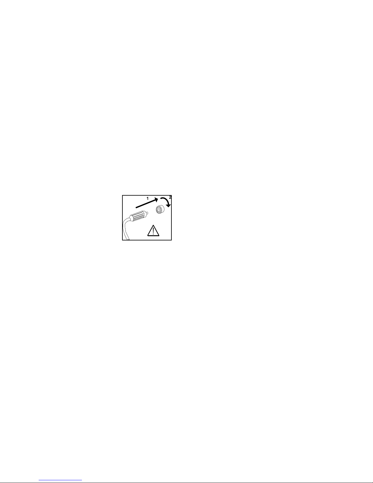
Important!
In order to avoid damage to
plugs and cables, good electric
contact is required when
connecting earth cable and
welding torch to the machine.
Connection of welding cables
Connect the welding cables and the return current
cable to the front of the machine.
Please note that the plug must be turned 45 degrees
after insertion into the socket - otherwise the plug
can be damaged due to excessive contact
resistance.
Connect always the TIG connection in the minus (-)
socket and the return current cable in the plus (+)
socket.
The control signals from the TIG torch are transformed to the machine through the circularly 7-pin
plug. When the plug has been assembled please
secure it by turning the "circulator" clockwise.
Connect the gas hose to the quick connection.
COATED ELECTRODES: Electrodes are marked
with a polarity on the packing. Connect the electrode
holder in accordance with this marking to the plus or
minus sockets of the machine.
Connection of remote control
Connect the remote control unit on the 7-ways plug
in the front of the machine. (OPTIONAL)
Usage of the machine
When welding, a heating of various components of
the machine takes place and during breaks these
components will cool down again. It must be ensured
that the air flow is not reduced or stopped.
When the machine is set for higher welding currents,
there will be a need for periods during which the
machine can cool down.
The length of these periods depends on the current
setting, and the machine should not be switched off
in the meantime. If the periods for cooling down
during use of the machine are not sufficiently long,
the overheating protection will automatically stop the
welding process and the yellow LED in the front
panel will come on. The yellow LED switches off
when the machine has cooled down sufficiently and
is ready for welding.
Instruction manual NXT200/250 AC/DC page 5
MAINTENANCE
Insufficient maintenance may result in reduced
operational reliability and could invalidate guarantee.
The NXT welding machines require virtually no
maintenance. However, exposure to extremely
dusty, damp or corrosive air can be damaging to
welding equipment.
Periodically maintenance
In order to prevent problems arising, the following
procedure should be observed at least once a year
or as required.
- Disconnect the machine from the mains supply
and wait 2 minutes before removing the covers.
- Clean the fan blades and the internal components
in the machine with clean, dry, low pressure
compressed air.
Calibration
The machine has been calibrated at the factory. The
certificate is valid for one year. If further
maintenance, or re-calibration is required, please
contact your NEXUS distributor or service department.
7 pin Plug connections
The functions of the 7 pin remote plug are as follows:
Pin 1 = red, water cooling
Pin 2 = black, torch switch
Pin 3 = not connected
Pin 4 = brown, water cooling
Pin 5 = not connected
Pin 6 = grey, torch switch
Pin 7 = not connected
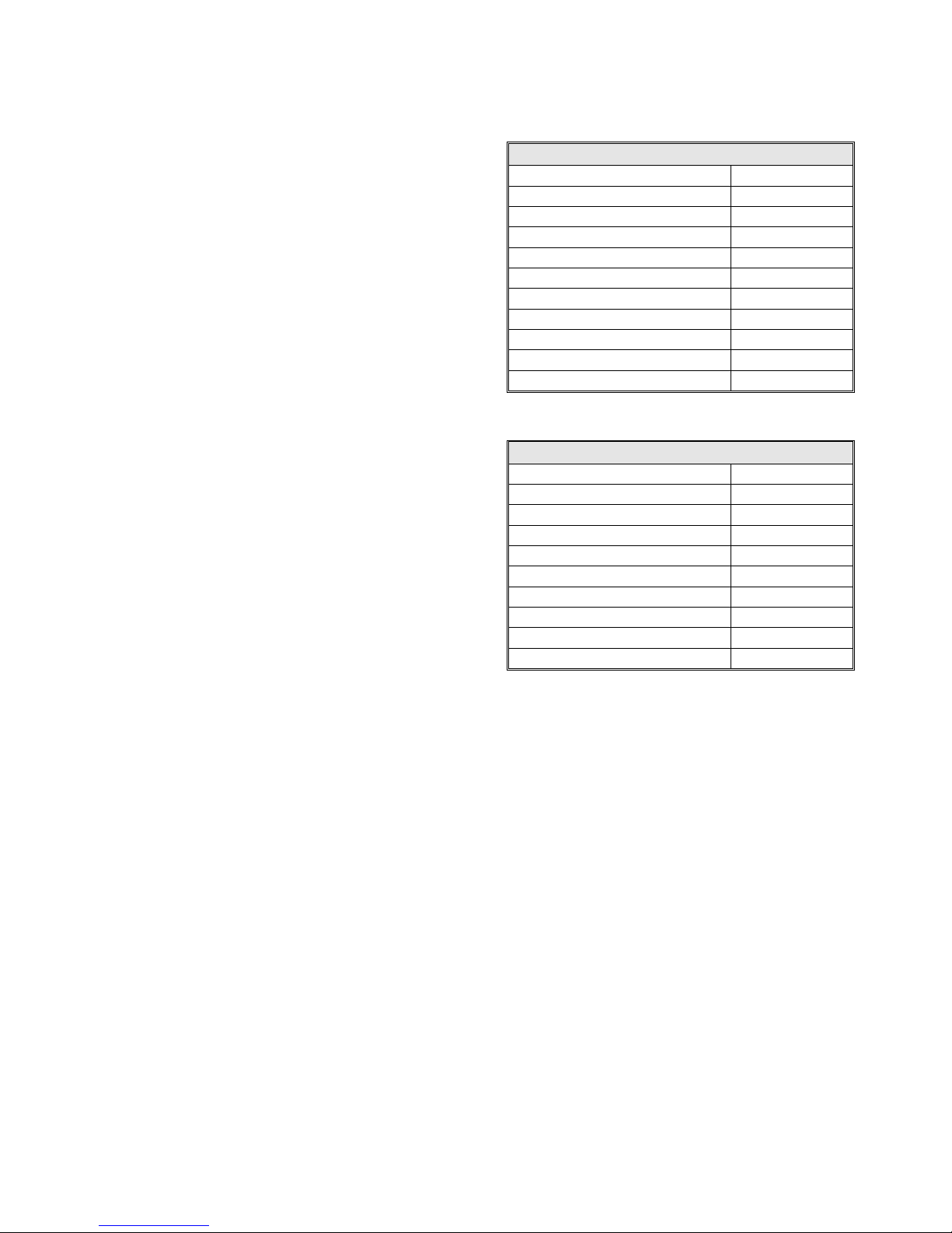
TECHNICAL DATA
NXT200 AC/DC
Mains voltage 1x230 V
PFC (power factor correction) Yes
Duty cycle 100 % TIG 140 A 40°C
Duty cycle 100 % MMA 130 A 40°C
Duty cycle 40 % TIG 200 A 40°C
Duty cycle 40 % MMA 170 A 40°C
Open circuit voltage 60 V
Current range TIG 7 – 200 A
Current range MMA 7 – 170 A
Dimensions (LxWxH) mm 205x345x475
Weight 20 kg
NXT250 AC/DC
Mains voltage 3x400 V
Duty cycle 100 % TIG 150 A 40°C
Duty cycle 100 % MMA 150 A 40°C
Duty cycle 35 % TIG 250 A 40°C
Duty cycle 35 % MMA 200 A 40°C
Open circuit voltage 65 V
Current range TIG 7 – 250 A
Current range MMA 7 – 200 A
Dimensions (LxWxH) mm 205x345x475
Weight 20 kg
Instruction manual NXT200/250 AC/DC page 6
INITIAL INSTRUCTIONS
All "parameters" are set by the use of only one
control knob. These parameters include current,
pulse time, slope-up time, etc.
This control knob is positioned in the middle of the
control panel. The digital display shows the value of
the parameter being set. The unit of measurement of
the parameter is shown at the left hand side of the
digital display.
Selection of a parameter is by means of the relative
keypad in the relevant section. The parameter
selected is indicated by a bright indication light. Then
turn the control knob to set the new value.
Storage of parameters
The machine memorises all settings also when the
mains voltage is switched off, thus ensuring that the
same machine settings are available when the
machine is switched on again.
Independent adjustments in the two welding
processes (MMA and TIG) are stored as well, so that
switching from one welding process to another does
not require a new setting of parameters.
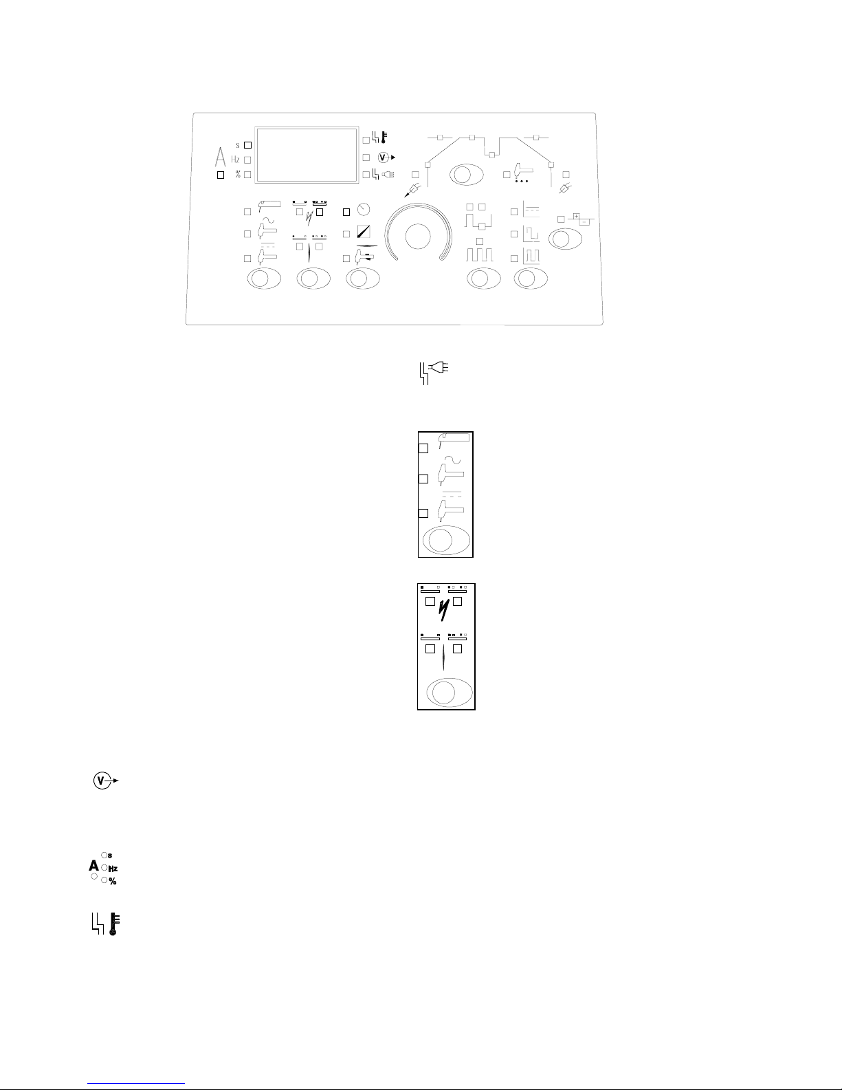
Setting of the machine
The following describes in detail the operation of the
machine.
Welding voltage
The welding voltage indicator is illuminated for
reasons of safety and in order to show if there is
voltage at the output connectors.
Units of measurement of the parameter
Units of measurement of the selected
parameter.
Overheating
The overheating indicator is illuminated if
welding is interrupted due to overheating of the
machine.
Input voltage variations
The mains error indicator is illuminated if the
mains voltage is more than 15% lower or higher than
the rated voltage.
Welding process
In this section it is possible to choose
the welding process:
• MMA electrode
• TIG AC/DC
• TIG DC
It is not possible to change welding
process during welding.
Torch switch functions
It is possible to choose between to
different methods of ignition for TIG
welding: High-Frequency (HF) and
LIFTIG ignition. Moreover, it is possible
to adjust the following parameters:
slope-up, slope-down and second
current level. It is not possible to
change setting during welding.
HF-ignition:
In HF-TIG ignition the TIG arc is ignited without
contact. A high-frequency (HF) impulse initiates the
arc when the torch trigger is activated.
The HF will not arise and the machine will stop if the
electrode is in contact with the workpiece. Detach
the electrode and start again.
LIFTIG-ignition:
In LIFTIG ignition the TIG arc is ignited after making
contact between the workpiece and the tungsten
electrode, after which the trigger is activated and the
arc is established by lifting the electrode from the
workpiece.
Two-times:
The welding process begins by pressing the torch
trigger. Welding continues until the trigger is
released again which effects the slope-down period.
 Loading...