

1
24-Port Fast + 2-Port Giga
Intelligent Ethernet Switch
SG9224B
WEB USER GUIDE
Date: 02, 2004
Standard Version
Version: 1.02
1

2
I. Table of Contents
1. Introduction
1-1. SG9224B with ARM S3C4510X01 Hardware Specification .……………………………. 5
1-2. SG9224B Management Software Specification ………………………............................5
1-3. System block diagram.............................…………………………………………..............6
2. Web Management Function.................................................................…………………….7
2-1. Default Web Operation..............................................................………………………….7
2-2. Web Management Home Overview ............................................………….....………... 8
2-3. Web Sitemap ..........................................………...........................…………………….. 10
2-4.System management function ............................................................. ………………..
A. System Login...........................……….........................................................................10
B. 802.1x configuration ........................................….......................................…………. 11
B-1 802.1x Configuration
B-2 802.1x Misc Configuration
B-3 802.1x Per Port Configuration
C. Administrator...............................................................................................................14
C-1 Authentication Configuration
C-2 System IP Configuration
C-3 System Status
C-4 System Update Configuration
D. Configuration Backup..............................................................................………….… 17
D-1 TFTP backup configuration
D-2 TFTP Restore Configuration
E. DHCP Server ................................................................................................……….. 18
E-1 DHCP Server configuration
E-2 DHCP server Show IP Binding
10
E-3 Exclude IP Configuration
E-4 Pool Configuration
E-5 Static IP configuration
F. Firmware Update...................................................................................................…..21
F-1 TFTP Update Firmware
F-2 Web Update firmware
G. Forwarding and filtering.....................................................................................……..23
G-1 forward configuration
G-2 forwarding Table
G-3 Mac filter Configuration
G-4 Mac Static configuration
H.IGMP Snooping.........................................................................…………………..….. 26
2

3
H-1 IGMP configuration
I. Log ….......................................................................................……………………… 27
I-1 Event Log Configuration
I-2 Show Event Log
I-3 SysLog Configuration
J. NTP Management .....................................................................…………..………. 29
J-1 NTP configuration
J-2 System Time Configuration
K Port control ........................................................................................………....……. 30
K-1 Bandwidth Control configuration
K-2 Module Information
K-3 Port Control Configuration
K-4 Port Mirroring Configuration
K-5 Port Statistics
L. QOS configuration................................................................................………….........35
M-1 QOS Configuration
M. RMON Configuration...............................................................…………………..........37
M-1 Alarm Configuration
M-2 Event Configuration
M-3 History Configuration
M-4 Statistics Configuration
N. SNMP Management....................................................................……………..............39
N-1 SNMP Configuration
N-2 SNMP Trap Configuration
O. Spanning Tree………………………………………………………………………..……. 40
O-1 Spanning Tree configuration
O-2 Spanning Tree Port Configuration
P. Stack Management ……………………………………………………………..……….... 42
P-1 Stack Configuration
P-2 Stack Status
Q. System Reboot ............................................................................…..………............. 43
Q-1 System Reboot
Q-2 Update System configuration
R. Trunk Management..........................................................……………..…………...... 44
R-1 Show LACP Status
R-2.Trunk Configuration
S. VLAN Configuration................................................................…………......................47
S-1 802.1q VLAN
3

4
S-2 Port based VLAN
S-3 VLAN Disable
4

5
1. Introduction
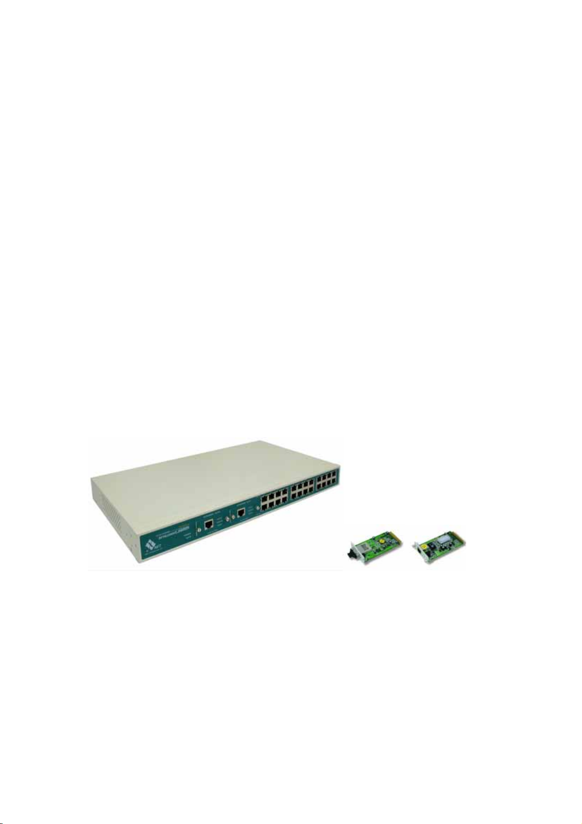
SG9224B is a non-blocking high performance Ethernet switch engine, integrated with 24
ports of 10/100Mbps and two ports of 10/100/1000Mbps. Each port can be either
auto-sensing or manually selected via EEPROM initial configuration or CPU on-line setting
to run at 10Mbps or 100Mbps or 1000Mbps speed rate, full or half duplex mode, enable or
disable flow control capability, the detail advance feature see the manual.
1-1. SG9224B with ARM S3C4510X01 Hardware Specification
Content:
A. MAC
(1) Version: VT6526
(2) SRAM: Embedded 3Mbit packet memory and 1Mbit control memory.
(3) Store & Forward
(4) External 25MHz crystal only.
(5) VT6526 Chip Package: 208-pin LQFP
B. CPU
(1) ARM: S3C4510X01
(2) Flash ROM: 32Mbit with SNMP/VLAN
(3) SDRAM: 8Mbyte (512K Wordsx16Bitsx2Banks)
(4) OSC: 50MHz, Internal clock is SDCLK (50MHz)
(5) HDLC: Serial Comm. I/F, Console port x 1
1-2. SG9224B Management Software Specification
TCP/IP ARP, ICMP, IP, TCP, UDP
SNMP V1, VIA private MIBS, MIB
SNMP
counters of groups 1,2,4,9
Web management server HTTP 1.0, CGI, SSI
Telnet server Telnet 1.0
Console Standard UART
Spanning tree protocol IEEE 802.1d
Two-Level priority Queuing IEEE 802.1p
Port-based VLAN (IVL) IEEE 802.1q
Protocol-based VLAN IEEE 802.1v
Trunk IEEE 802.3 ad
5
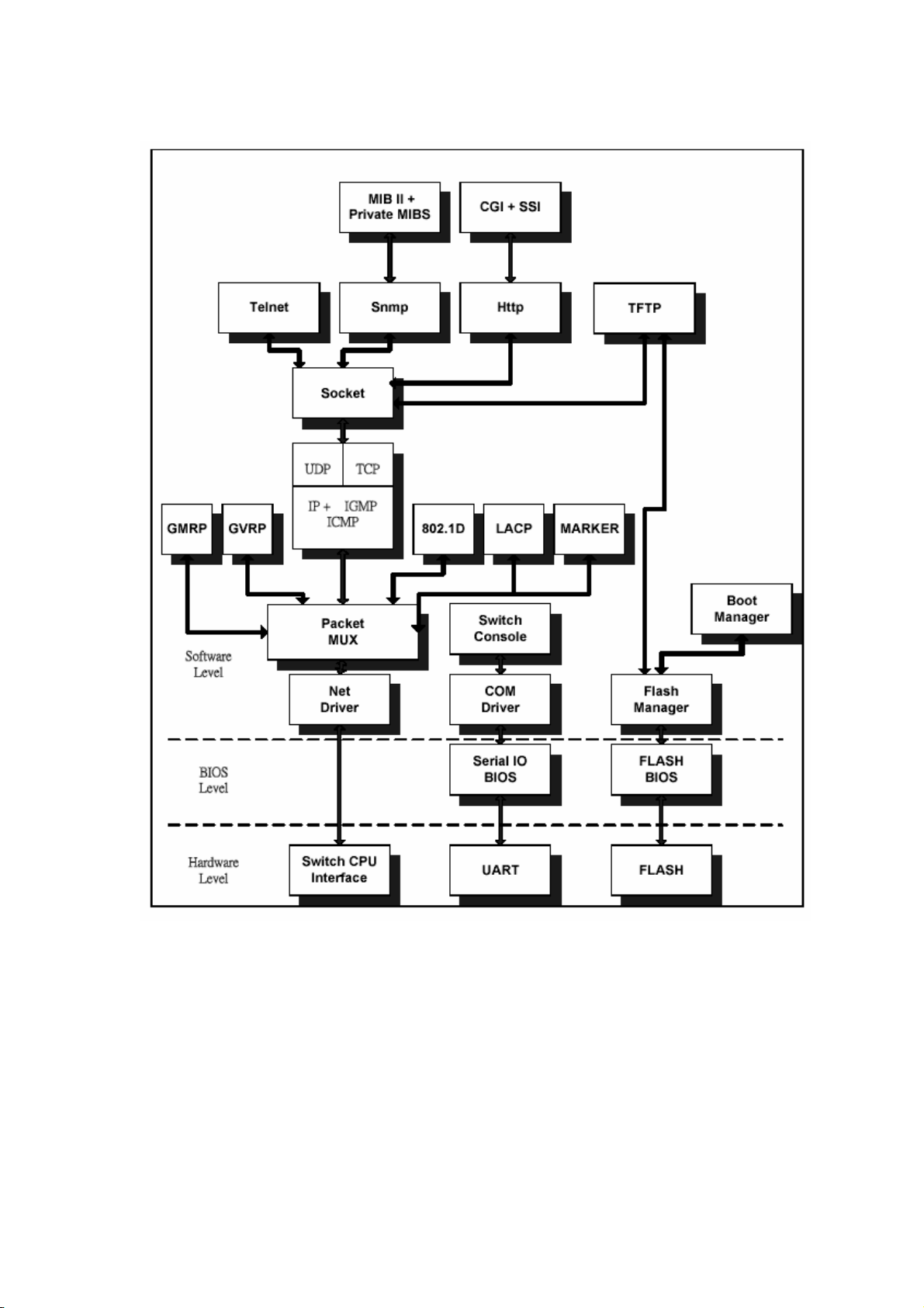
1-3 System block diagram
6
6
2. Web Management Function
2-1 Default Web Operation
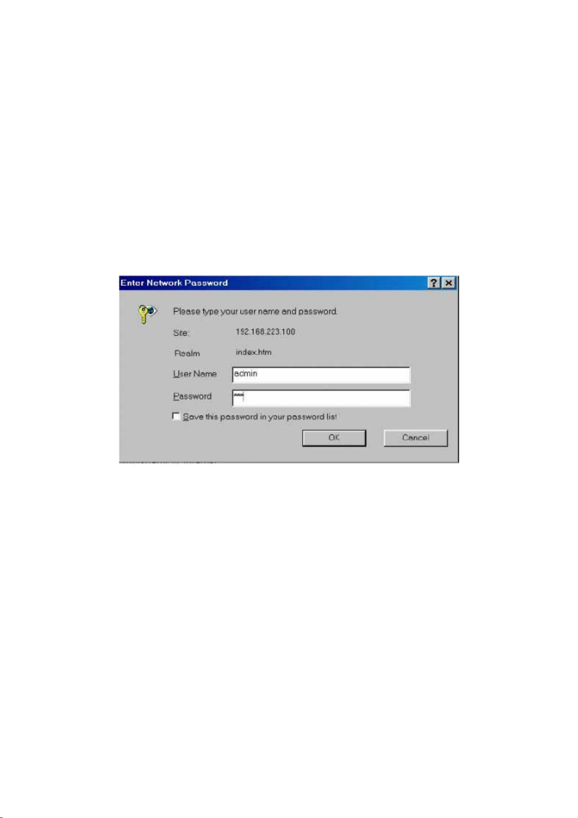
2-1-1. Login: The SG9224B provides a Web browser to manage the switch, the default
Log in values as follows:
a. Default Login V alue:
(1) IP Address: 192.168.2.1
(2) IP Sub network: 255.255.255.0
(3) User Name: admin
(4) Password: system
7
2-1-2.Change your System Configuration:
a. Change the configuration you needs.
b. Follow the Session C-4. ”System Update configuration” and write to device’s system
memory.
c. Reboot the switch device.
7
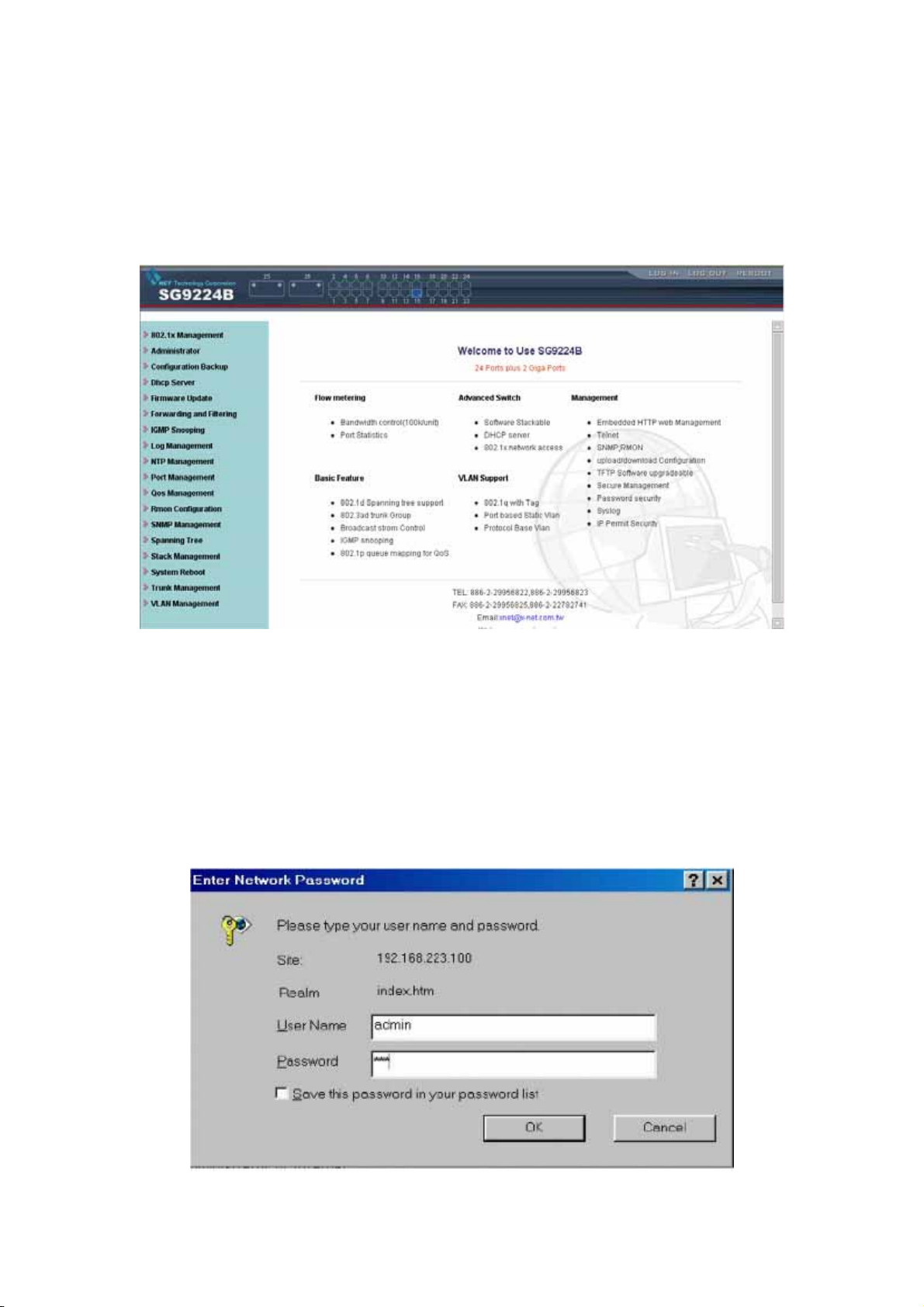
2-2. Web Management Home Overview
2-2-1. This is a Web Browser Page.
8
2-2-2. The system has three frames to combine
1. Upper Frame (Logo & Port Status)
2. Left Frame (UNCTION MENU)
3. Middle Frame (Content)
2-2-3. First logon the System, You should fill the correct ID & password.
8
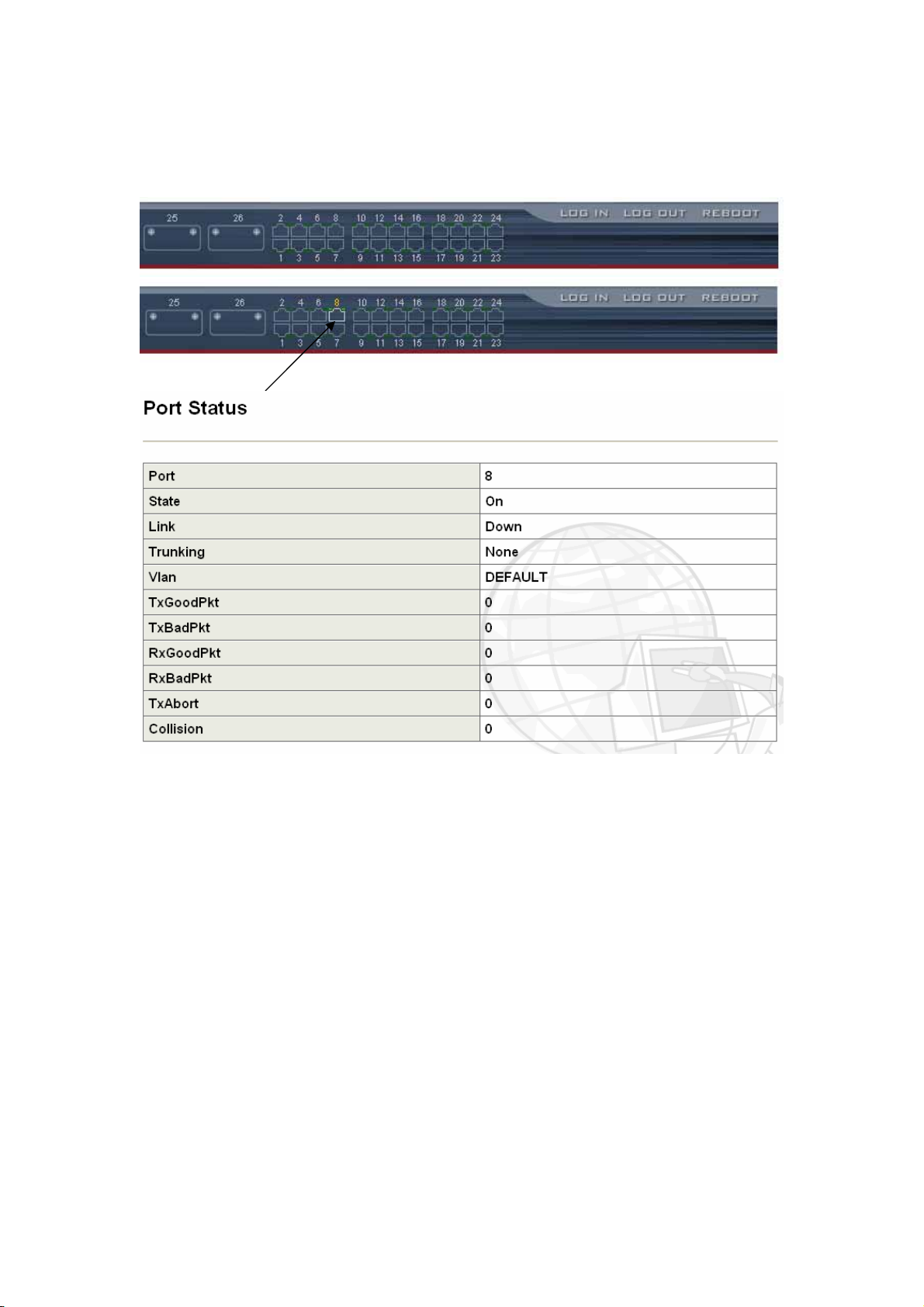
2-2-4. Port status
This page can see per port status that click the upper switch’s banner.
9
1. State : Display port link status disable or enable. “No Link” will be treated
as “off ”.
2. Link Status : Display the current link status (Down or Link) of the port.
3. Trunking : Display the port whether in the Trunk mode.
4. TxGoodpkt : Display the transfer succeed package,.
5. TxBadPkt : Display the transfer failure package.
6. RxGoodPkt: Display the Received succeed package.
7. RxBadPkt : Display the Received failure package.
8. Port Security: Display the port security is enable or disable.
9. TxAbort : Display the Transfer abort package.
10.Collision : Display the collision result.
9
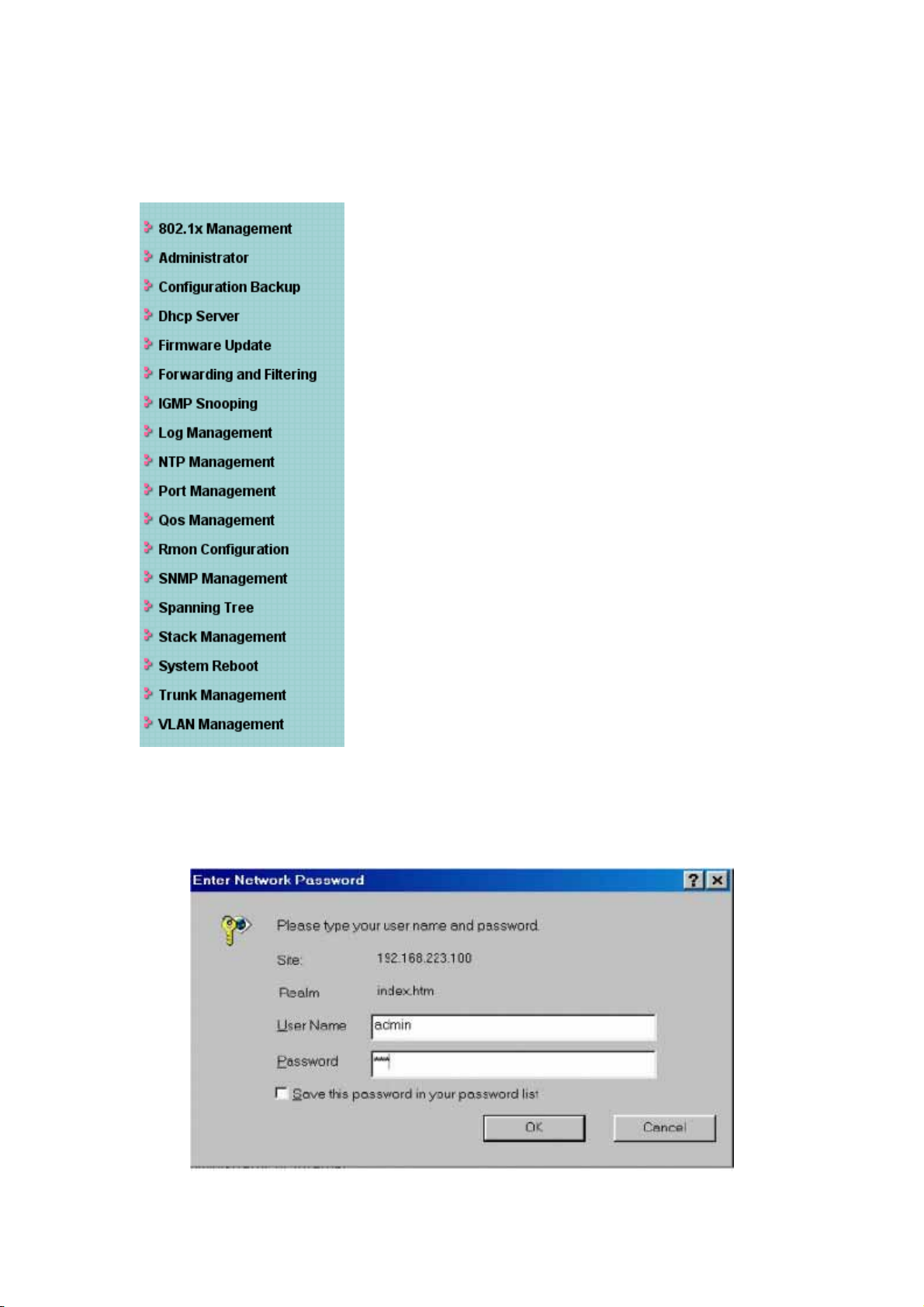
2-3. Web sitemap
There are many management functions, include:
10
2-4 System management function
a. System Login
Login the Web management
10
11
B. 802.1x Configuration
System Configuration
The IEEE802.1x makes using of the physical access characteristics of IEEE802 LAN
infrastructures in order to provide a means of authenticating and authorizing devices
attached to a LAN port that has point-to-point connection. And of preventing access to the
port Which the authentication and authorization process fails.
To enable IEEE802.1x, you still to fill in the authentication server information.
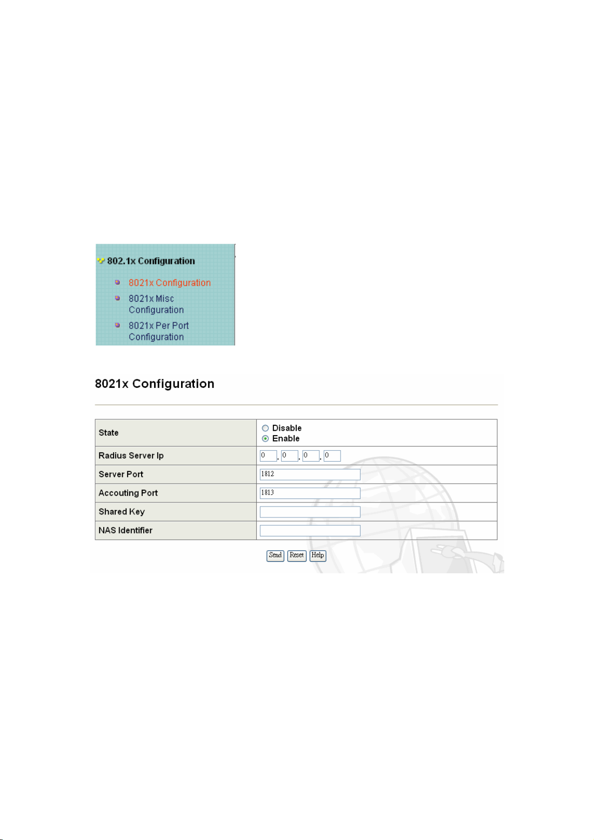
B-1 Configuration of 802.1x
• IEEE802.1x Protocol: Enable/disable IEEE802.1x protocol.
• Radius Server IP Address: the IP address of the authentication server.
• Server Port: The UDP port number used by the authentication server to
authenticate.(The default Port of the 802.1x)
• Accounting Port: The UDP port number used by the authentication server to retrieve
accounting information.
• Shared Key: A key is shared with the switch and authentication server.
• NAS Identifier: A string is used to identify this switch
11
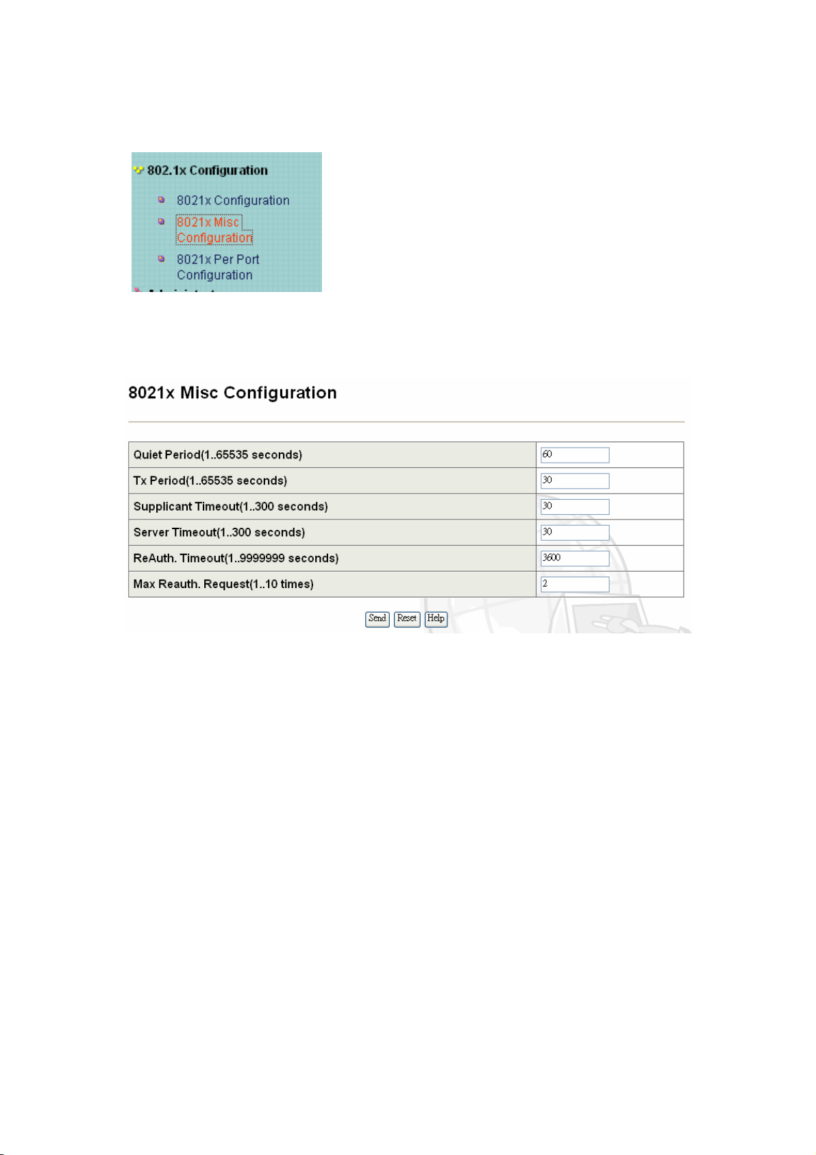
B-2 802.1x Misc Configuration
Misc Configuration
In this page, you can change the values for the IEEE802.1x parameter:
12
• Quiet Period: define periods of time during which it will not attempt to acquire a
supplicant (Default time is 60 seconds).
• Tx Period: use to determine when an EAPOL PDU is to be transmitted (Default
value is 30 seconds).
• Supplicant Timeout: determine timeout conditions in the exchanges between the
supplicant and authentication server (Default value is 30 seconds).
• Server Timeout: determine timeout conditions in the exchanges between the
authenticator and authentication server (Default value is 30 seconds).
• ReAuthMax: determine the number of re-authentication attempts that are permitted
before the specific port becomes unauthorized (Default value is 2 times).
• Reauth Period: determine a nonzero number of seconds between periodic
re-authentication of the supplications (Default value is 3600 seconds).
12
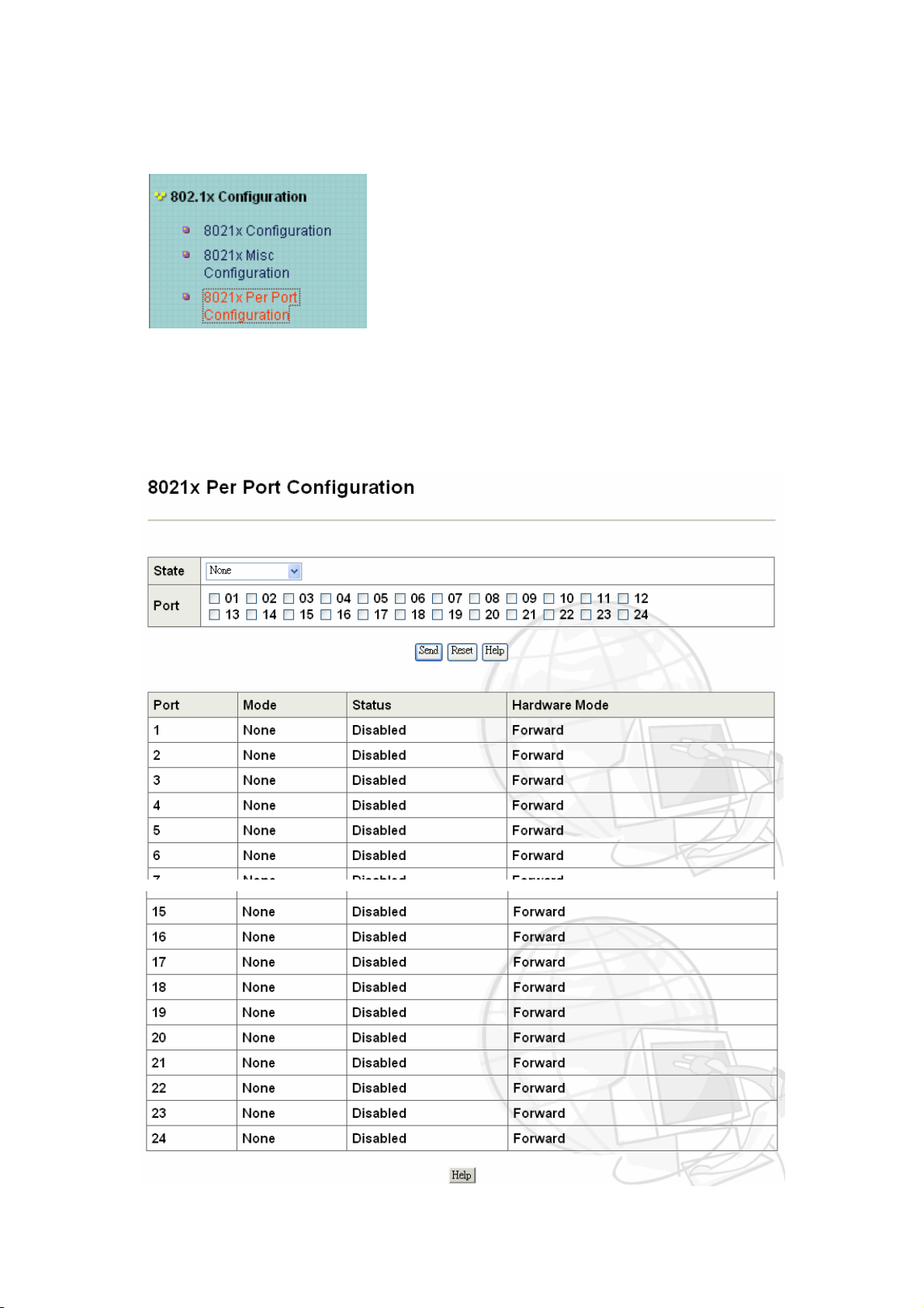
B-3.802.1x Per port configuration
Per Port Configuration
In this page, you can select the specific port and configure the authorization state.
Each port can select four kinds of authorization state:
13
13
14
• Fu: force the specific port to be unauthorized.
• Fa: force the specific port to be authorized.
• Au: the state of the specific port was determined by the outcome of the
authentication.
• No: the specific port didn't support 802.1x function
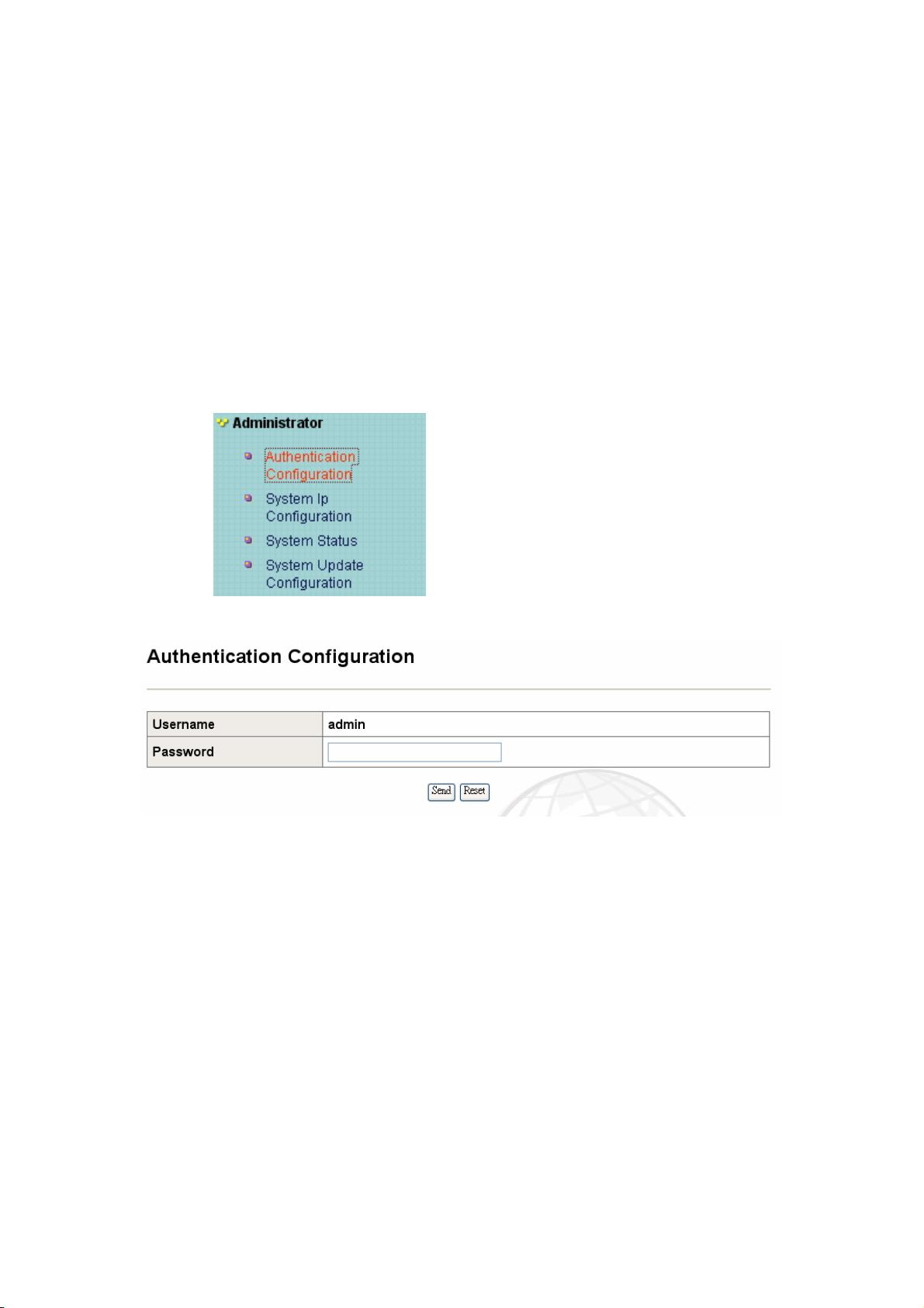
C、Administrator
C-1 Authentication Configuration
14

15
C-2 System IP Configuration
z IP address: User can assign a DHCP Client or Static IP to this intelligent switch.
Specify an IP address / Subnet Mask / Default Gateway:
User can configure the IP setting or change the IP setting, then click “send” icon. Reset
switch and use new IP address to browser this Web management.
z Save New IP: When user will save the new IP configured, user should be to “System
Update Configuration“, click “Write“ and “Reboot system”.
C-3、System Status.
Can see your system firmware version or MAC ID or switch location setting by this item.
15
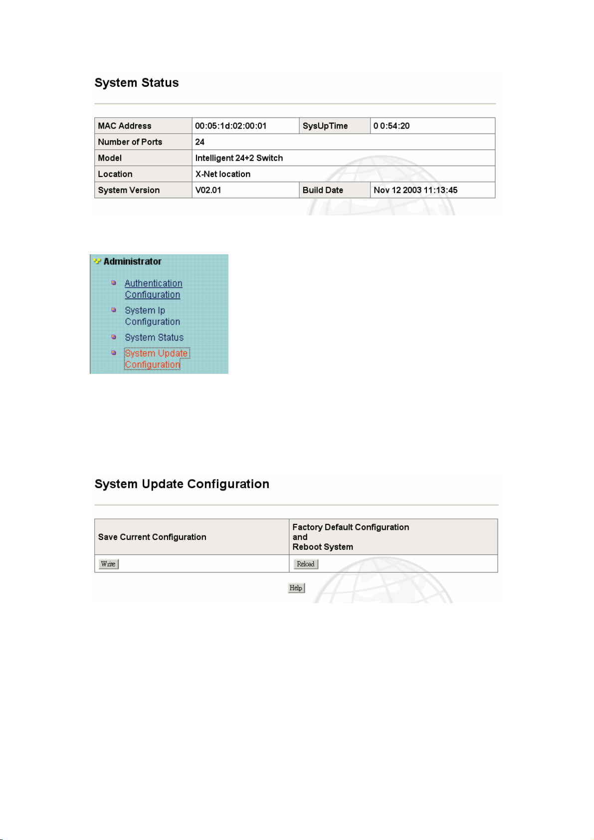
C-4、System Update Configuration
16
Can save your new configuration after you change the any system parameter, or you can go
back to the system default value by this icon. We suggest user to go to “System Update
Configuration” when user has changed any setting. Then go to Q. “System Reboot” reboot
device.
The “Write” save the new configuration to system flash memory. The “Reload” is back to
factory default configuration.
16

17
D: Configuration Backup
D-1: TFTP Backup configuration
Use this page to set TFTP server IP address. You can save current Configuration value from
here, then go to the TFTP restore configuration page to restore the configuration value.
D-2、TFTP Restore Configuration
Use this page to set TFTP server address. You can restore configuration value from here, but
you should put back image in TFTP server, switch will download back flash image.
17

18
E. DHCP Server
E-1 DHCP Server configuration
You can use the Dynamic Host Control Protocol (DHCP) to automatically assign reusable IP
addresses to DHCP clients.
z DHCP Server : Disable / Enable.
z Network : You can specify your network address (class C only).
z Network mask : The mask value, usually we use the 255.255.255.0
z Default Gateway : The IP specify the device to connect to the internet.
z DNS Server : You can choose your DNS Server, in order to use the domain in
your DHCP network.
z Domain Name : You can specify the name instead of the IP.
z Lease Time : By default, IP address assigned by a DHCP server comes with a
one-day lease, which is the amount of time that the address is valid. You can change the
lease value for an IP address.
z Excluded-IP : The IP did not set in the NAT address.
18

E-2、DHCP server Show IP Binding
See the Server IP binding configuration from this function.
19
E-3、Exclude IP Configuration
You can configure “Excluded IP” address of DHCP Server from here, and see the setting
range.
19

20
E-4、Pool Configuration
According to your network environment, you can set DHCP Server Pool from this function. If
you have many VLAN or different segment network, you should configure the DHCP Server
Pool to assign different IP network segment.
z Pool Name : Creates a name for the DHCP Server Pool.
z Network. Or Network Mask : Specifies IP address for the network or subnet
network that IP address could pool with the DHCP Server.
20

21
E-5、Static IP configuration
Static IP Configuration could bind a mapping between the DHCP client IP address and Media
Access Control (MAC) address. Also, DHCP pool should not use this specified IP address to
assign to any host.
F. firmware Update
F-1 TFTP update Firmware
The firmware update can choose “TFTP Update firmware” or “Web Update Firmware”.
Update your firmware by using TFTP client if you have TFTP server. Specify the IP address
of your TFTP server and name of image file to upgrade your new firmware.
z The menu provides TFTP Server function to allow a user to update firmware:
* Install TFTP Turbo98 and execution.
* Copy firmware update version image bin to TFTP Turbo98 directory.
21

* In web management select administrator—TFTP update firmware.
* Download new image bin file then in web management press <update firmware>.
*After update finished, press <reboot> to restart switch. And save the configuration
F-2 Web upload image file
22
The menu provides the Web update function to allow a user to update firmware.
z You can download the Image file of the switch from Xnet web site www.x-net.com.tw .
z Use the Web Browser to specify the position of the file and “submit”
z After upload, and you need to reboot the system
22

G. Forwarding and Filtering
G-1 Forward configuration
23
• MAC Address Age-out Time
Type the number of seconds that an inactive MAC address remains in the switch's
address table. Default is 300 seconds.
G-2: Forwarding Table
This table can display all of the MAC addresses which has received packet.
23

G-3、 MAC filter configuration
24
MAC address filtering allows the switch to drop traffic. Traffic is filtered based on the
destination address.
24

25
z In the “MAC Address” field, enter the MAC address that user wants to filter.
z If tag-based (802.1Q) VLAN has set up, type the VID (VLAN ID) to associate with the
MAC address.
z Then click “send” to configure the parameter.
G-4 MAC static configuration
25

26
H. IGMP Snooping
Internet Group Management Protocol (IGMP) Snooping, which enables the Switch to read
IGMP packets being forwarded through the Switch in order to obtain forwarding
information.
H-1 IGMP configuration
The SG9224B supports IP multicast, user can enable IGMP protocol on Web Management’s
setting advanced page, and display the IGMP snooping information in this page. You can
view difference multicast group, VID and member port in here. The IP multicast addresses
range is from 224.0.0.0 through 239.255.255.255.
The Internet Group Management Protocol (IGMP) is an internal protocol of the Internet
Protocol (IP) suite.
IP manages multicast traffic by using switch, router, and host that support IGMP. Enabling
IGMP allows the ports to detect IGMP queries, reports packets and manage IP multicast
traffic through the switch. IGMP has three fundamental types of message as follows:
26

27
I. Log Management
I-1 Event log Configuration
It is to set log size and to enable time of log info. You can set memory size of log table
between 16384 and 524288 bytes. Default is 16640 bytes. If you enable timestamp, log table
will display time of log info entries when they generated.
I-2 Show Event Log
“Show EventLog” display log information status.
27

28
I-3 Syslog configuration
Setting a IP address of SysLog Server and facility. Enable this function, it will be sent to
SysLog Server once a log entry is generated. As below figure, the table will display SysLog
Server setting. However, you can only set 8 servers to be allowed.
28

29
J.NTP Management
J-1 NTP configuration
NTP (Network Time Protocol) setup the switch time protocol .When we use the login
calculate and other function we need the correct time setup.
The IP “128.102.16.2” is the “Ger Lin Wetz” Time.
J-2.System time configuration
It also can adjust time parameter for your local time.
29

30
K. Port control
K-1 Bandwidth Control Configuration
z Bandwidth Control: The switch supports by-port ingress and egress rate control
by-port (Port 1-24). For example, assume port 1 is 10Mbps, users can set effective
egress rate is 1Mbps, ingress rate is 500Kbps. It will perform flow control or
backpressure to confine the ingress rate to meet the specified rate.
Ingress: Type effective ingress rate and valid range is 0 ~ 1000K. The degree is 100K.
0: disable rate control. 1 ~ 1000: valid rate value.
Egress: Type effective egress rate and valid range is 0 ~ 1000K. The degree is 100K.
0: disable rate control. 1 ~ 1000: valid rate value.
30

K-2 Module Information
Display information of Giga bit module if there is Giga bit module to be installed.
31
K-3 Port control configuration
“Port Control Configuration” can change status every port.
z State: Disable or enable this port control.
z Negotiation: Set force, auto or N-Way mode for port.
z Speed: Set 100 or 10Mbps speed on Port1~Port24 and 1000or 100 or 10Mbps speed on
Port25~Port26 (depend on module card mode).
z Duplex: Full-duplex or half-duplex mode.
z Flows control:
Full: Full enable or disable in Full-Duplex mode.
Half: Half set backpressure to enable or disable in Half-Duplex mode.
31

32
z Port Security: A port in security mode will be “locked” without permission of
learning. Only the incoming packets with MAC already existing in the address table can
be forwarded normally. User can disable the port from learning any new MAC addresses,
then use the static MAC addresses screen to define a list of MAC addresses that can use
the secure port. Enter the settings, then click Apply button to changes on this page.
address
32
33
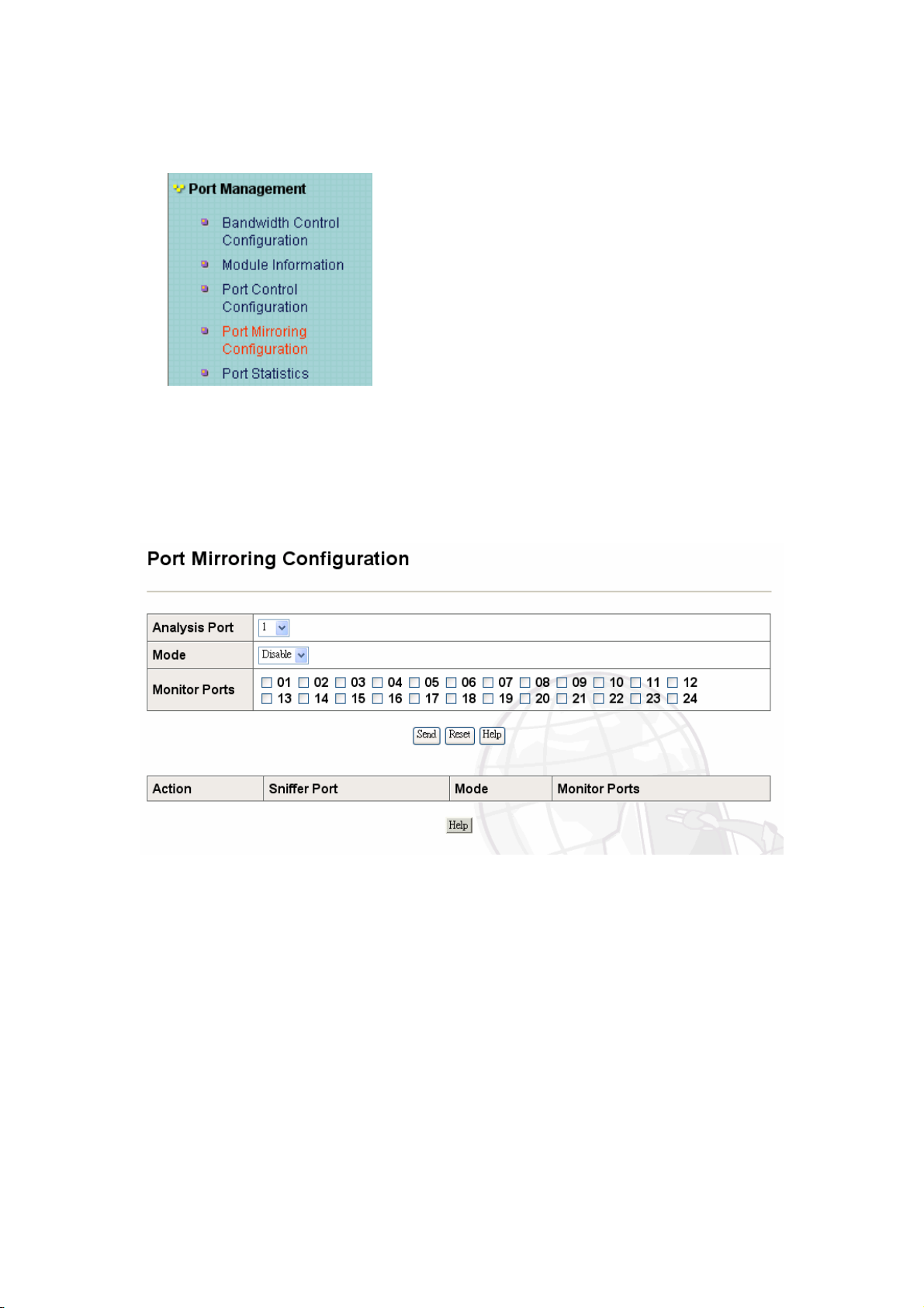
K-4 Port Mirroring Configuration
This Port offers a method for monitor traffic at networks. A traffic packet can be monitored
through the specific port. That is, traffic goes in or out the monitor port and will be duplicated
into the sniffer port.
z Analysis Port: choose the port to analysis other port and set up to Sniffer mode:
Disable\Rx\Tx\Both.
z mode: you can choose monitor Receive or Transmit or Both.
It means the Sniffer port can see all monitor port traffic. You can connect Sniffer port to
LAN Analyzer or NetxRay.
z Monitor Port: The port is you want to monitor. All monitor port traffic will be copied to
Analysis port. You can select 24 monitor ports in the switch. User can only choose a
Sniffer mode which port wants to monitor.
If you want to disable the function, you should select monitor port to none.
33

K-5 Port Statistics
Following information provides a view of the current status of the unit.
34
34

L . QOS configuration
L-1 QOS configuration
Configure parameters of QOS.
Max Bridge Transmit Delay Bound Control:
Limit the packets queuing time in switch. If enable, the packets queued exceed will be
drop. The valid value is 1sec, 2sec, 4sec and off. Default is off.
Broadcast Storm Filter Mode:
The valid threshold value is 5%, 10%, 15%, 20%, 25% and NO.
Low Queue Delay Bound State:
Limit the low priority packets queuing time in switch. If enable, the low priority packets
stays in switch if exceed Low Queue Max Delay Time, it will be sent.
35
Low Queue Max Delay Time:
To set the time that low priority packets queuing in switch. Default Max Delay Time is
255ms. The range is 1~255ms.
QoS Policy:
High Priority Levels: 0~7 priority level can map to high or low queue.
First Come First Service:
The sequence of packets are depend on arrive order.
All High before Low:
The high priority packets sent before low priority packets.
WRR:
Weighted Round Robin. Select the preference given to packets in the switch’s
high-priority queue. These options represent the number of high priority packets sent
before one low priority packet has sent. For example, 5 High: 2 Low means that the
switch sends 5 high priority packets before 2 low priority packets.
Priority:
This static priority base on Port, if you set one port to be high priority, incoming frame
from this port that it always high priority frame.
35

36
36

M. RMON Configuration
M-1: Alarm Configuration
37
Configure parameters of Alarm group of RMON.
M-2: Event Configuration
Configure parameters of Event group of RMON.
37

M-3 History Configuration
38
Configure parameters of History group of RMON.
38

M-4: Statistics Configuration
Configure parameters of Statistic group of RMON.
39
N. SNMP Management.
N-1: SNMP Configuration
Configure community string of SNMP and parameters of system group of MIBs.
39

N-2 SNMP Trap Configuration
40
Configure four SNMP Trap stations to get SNMP Trap.
O. Spanning Tree
O-1: Spanning Tree Configuration
40

41
The Spanning-Tree Protocol (STP) can avoid to the blocking of links between switch form
loops within the network. When multiple links between switches are detected, a primary link
is established. Duplicated links are blocked from use and become standby links.
When STP enabled, to ensure that only one path at a time is active between any two nodes on
the network.
Enable Spanning-Tree Protocol can setup at Web Management which is advanced item, select
enable Spanning-Tree protocol. We are recommended that you enable STP on all switches
ensures a single active path on the network.
You can view spanning tree information about the Root Bridge. Such as following
screen.
O-2: Spanning Tree Port Configuration
Configure Spanning Tree Port Parameters.
Port Priority: You can make it more or less likely to become the root port, the range is 0-255
and default setting is 128. The lowest number has the highest priority.
Path Cost: Specifies the path cost of the port that switch uses to determine which port is the
forwarding port the lowest number is forwarding port, the range is 1-65535 and
default value base on IEEE802.1D, 10Mb/s = 50–600, 100Mb/s = 10–60,
1000Mb/s = 3–10.
41

42
P. Stack Management
P-1.Stack Configuration
Configure switch stack’s settings. If you want to stack your switch, please set the same group
name and different module number in the switch.
42

43
P-2 Stack Status:
This table will display stack status.
43

Q. System Reboot
Q-1.System Reboot
Reboot the Switch to restart and initial it.
44
R. Trunk Management
R-1.Show LACP Status
]
The Link Aggregation Control Protocol (LACP) provides a standardized means for
exchanging information between Partner Systems on a link to allow their Link Aggregation
Control instances to reach agreement on the identity of the Link Aggregation Group to which
the link belongs, move the link to that Link Aggregation Group, and enable its transmission
and reception functions in an orderly manner. In conclusion, Link aggregation lets you group
up to eight consecutive ports into a single dedicated connection. This feature can expand
bandwidth to a device on the network.
44

45
LACP operation requires full-duplex mode, more detail information refers to IEEE
802.3ad.
Aggregator setting
All ports support LACP dynamic trunk group. If connecting to the device that also supports
LACP, the LACP dynamic trunk group will be created automatically.
R-2.Show trunk
45

46
z System Priority: A value used to identify the active LACP. The switch with the lowest
value has the highest priority and is selected as the active LACP.
46

47
z Group ID: There are seven trunk groups to provide configure. Choose the "group id"
and click "Send".
z Work ports: Allow max four ports can be aggregated at the same time. If LACP static
trunk group, the exceed ports is standby and able to aggregate if work ports fail. If local
static trunk group, the number must be as same as the group member ports.
z Select the ports to join the trunk group. Allow max four ports can be aggregated at the
same time.
z LACP: If enable, the group is LACP static trunk group. If disable, the group is local
static trunk group.
z If LACP enable, you can configure LACP Active/Passive status in each ports on State
Activity page.
Link Aggregation Control Protocol (LACP) is part of an IEEE specification (802.3ad) that
allows you to bundle several physical ports together to form a single logical channel. LACP
allows a switch to negotiate an automatic bundle by sending LACP packets to the peer. It
performs a similar function as Port Aggregation Protocol (PAgP) with Cisco EtherChannel.
S. VLAN
VLAN configuration
A Virtual LAN (VLAN) is a logical network grouping that limits the broadcast
domain. It allows you to isolate network traffic so only members of the VLAN
receive traffic from the same VLAN members. Basically, creating a VLAN from a
switch is logically equivalent of reconnecting a group of network devices to
another Layer 2 switch. However, all the network devices are still plug into the
same switch physically.
47

S -1-1
Configure port VID settings:
From the main Tag-based (IEEE 802.1Q) VLAN page, click Port VID Settings.
Support Tag-based VLAN (IEEE 802.1Q VLAN):
Tagged-based VLAN is an IEEE 802.1Q specification standard. Therefore, it is possible to
create a VLAN across devices from different switch venders. IEEE 802.1Q VLAN uses a
technique to insert a “tag” into the Ethernet frames. Tag contains a VLAN Identifier (VID)
48
that indicates the VLAN numbers.
S -1-2
48

GVRP (GARP [Generic Attribute Registration Protocol] VLAN Registration
Protocol)
49
GVRP allows automatic VLAN configuration between the switch and nodes. If the switch
is connected to a device with GVRP enabled, you can send a GVRP request using the
VID of a VLAN defined on the switch, the switch will automatically add that device to
the existing VLAN.
S -1-3
49

50
Port VID (PVID)
Set the port VLAN ID that will be assigned to untagged traffic on a given port. This feature
is useful for accommodating devices that you want to participate in the VLAN but that
don’t support tagging. SG9224B each port allows user to set one PVID, the range is 1~255,
default PVID is 1. The PVID must as same as the VLAN ID that the port belong to VLAN
group, or the untagged traffic will be dropped.
Ingress Filtering
Ingress filtering lets frames belonging to a specific VLAN to be forwarded if the
port belongs to that VLAN. SG9224B have two ingress filtering rule as follows:
Ingress Filtering
Rule 1: Forward only packets with VID matching this port's configured VID.
Rule 2: Drop untagged Frame.
50

51
S -1-4
51

52
S-2 Port Based VLAN
Port-based VLAN
Packets can go among only members of the same VLAN group. Note all unselected ports are
treated as belonging to another single VLAN. If the port-based VLAN enabled, the
VLAN-tagging is ignored.
z VLAN ID: Click add to create a new VLAN group.
z VLAN Name: Enter the VLAN name, group ID and select the members for the new
VLAN.
z Select port: you can select many groups, you can click the “Send” to Set the VLAN
groups.
NOTE: If the trunk groups exist, you can see it (TRK1, TRK2…..) in selection menu of ports,
and you can configure the member of the VLAN or not.
52

S -3 Disable VLAN
53
VLAN Default Configuration: Disable. You can delete all the VLAN setting by use this
Disable VLAN function.
53
 Loading...