

Page 1
Installing the FM Coupler in
your vehicle
Page 2
Please note that the CLA cable supplied with your device includes permanently attached ferrite
beads at each end. It is the responsibility of the user to use the cable with the ferrite beads.
The user is cautioned that changes or modifications not expressly approved by XM Satellite Radio,
Inc. can void the user’s authority to operate this device.
This device complies with Part 15 of the FCC Rules. Operation is subject to the following two
conditions: (1) This device may not cause harmful interference, and (2) this device must accept any
interference received, including interference that may cause undesired operation.
This equipment has been tested and found to comply with the limits for a Class B digital device,
pursuant to Part 15 of the FCC Rules. These limits are designed to provide reasonable protection
against harmful interference in a residential installation.
This equipment generates, uses and can radiate radio frequency energy and, if not installed and
used in accordance with the instructions, may cause harmful interference to radio communications.
However, there is no guarantee that interference will not occur in a particular installation. If this
equipment does cause harmful interference to radio or television reception, which can be
determined by turning the equipment off and on, the user is encouraged to try to correct the
interference by one or more of the following measures:
- Reorient or relocate the receiving antenna.
- Increase the separation between the equipment and receiver.
- Connect the equipment into an outlet on a circuit different from that to which the receiver is
connected.
- Consult the dealer or an experienced radio/TV technician for help.
FCC INFORMATION:
2 3
FCC Information Contents
Installation Locations
5
Installing the FM Coupler Overview 4
External FM Whip Antenna Routing 8
Internal On Glass Antenna Routing 12
Installation Setup 6
Page 3
Installing the FM Coupler Overview Installation Locations
To install the FM Coupler, first find a suitable location that works in your vehicle.
You need to determine the location of your vehicle’s FM Antenna and properly
routing the FM Coupler cables to your FM antenna..
For best audio performance, install the FM Coupler by either clipping it directly
to an external whip antenna (locations 1 through 4) or against an interior
on-glass antenna using the additional window Contact Bracket (locations 5
through 7). Step by step installation instructions are provide later in this document.
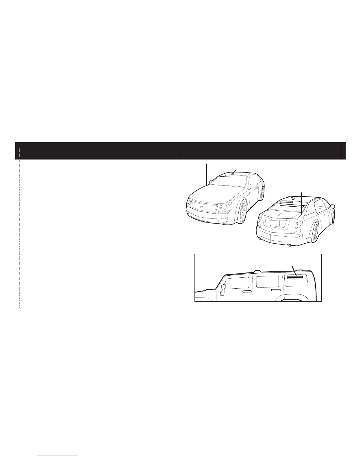
Your vehicle’s FM antenna will be located in one of seven common locations:
1. front fender
2. rear fender
3. roof top front
4. roof top rear
5. adhered on edges of windshield
6. adhered on top of rear window
7. adhered on rear side glass (in some SUVs)
1
3
5
4
6
2
7
4 5
Page 4
Install your XM Radio and vehicle kit as described in your XM Radio User’s Manual but leave
the XM antenna disconnected from the dock.
1.
Locate your vehicles FM antenna and determine the best routing method to get the FM Coupler
output cable to the FM antenna. (For external whip antennas, the Coupling Clip needs to be
routed outside of the vehicle. For internal on glass antennas, all routing is inside the passenger
compartment and the Contact Bracket is used.
2.
Connect the FM Coupler input cable to the vehicle dock antenna input.
3.
The following steps will guide you through the installation of your FM Coupler
4.
Connect the XM Antenna to the FM Coupler antenna input, located on the coupler module
about 2 feet from the end of the input cable. Tuck away any excess input cable and the coupler
module behind dash or other hidden location for a clean installation.
5.
Route the output cable with Coupling Clip to your vehicle FM antenna. (This guide assumes you
have already installed your XM antenna per the instructions in your XM radio user guide. The
position of the XM antenna in the illustration below is for example only. There is no need to
change your XM antenna installation.)
Note: When routing the FM Coupler cable use pre-existing wire channels whenever possible to
avoid loose wires on the interior of the vehicle which are susceptible to damage and to maintain
a professional looking installation. Route cable carefully by taking notice of how doors open and
close, as well as how seats move when they are adjusted so you can be certain there is ample
clearance provided for the cable.
Avoid inadvertent damage that may be caused by kinking, crimping, twisting or chafing the
cables. Secure and tie wrap the excess cable under your dash board, between the seat and the
console, or on the floor under a seat or floor mat. Securing the excess cable will help to prevent it
from interfering with the everyday use of your vehicle, improve the appearance of the installation, and avoid any undesirable accidental damage to the cables that might result in loss of
satellite signal or FM Coupler performance.
without boot
glass
contact
bracket
inside your
vehicle
outside
car dock
XM car
antenna
coupling
clip
coupling
module
input
cable
output
cable
external
antenna
External Antenna Internal on-glass antenna
boot
power
XM antenna
Installation Setup Installation Setup
6 7
Page 5

XM car
antenna
XM
receiver
coupler
clip
coupler
module
XM car
antenna
XM
receiver
coupler
clip
coupler
module
8 9
External FM Whip Antenna Routing External FM Whip Antenna Routing
For a whip antenna in the rear, route the output cable along the floor under the
door jam trim or under the carpet to the rear of the passenger compartment as
shown in the illustration below. Route the cable into the trunk through available
wire channels and out of the trunk to the external whip antenna. Always cross
the weather seal at the lowest part of the trunk to reduce water leaks.
For a whip antenna in the front, route the output cable under the dash or carpet
to the door jam and outside as shown in the illustration. Route the cable across
the weather seal near the bottom of the door to reduce water leaks.
Page 6

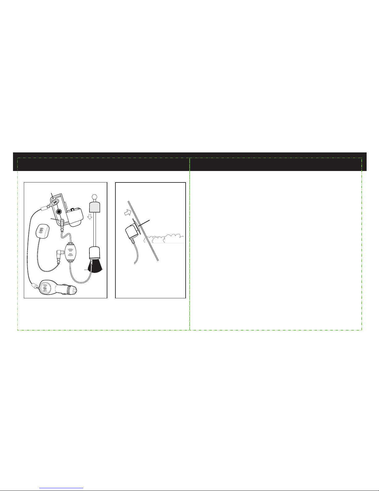
After routing the cable, if you have an external whip or roof mount FM
antenna, attach the Coupling Clip directly to the base of the antenna as
illustrated below. Cover the Clip with the rubber boot provided to protect
and secure the clip. Secure the cable inside the trunk or hood to avoid
interference or accidental damage.
6.
car
antenna
snap the antenna
clip into place
rubber boot
Slide the boot over the
top of your antenna.
Slide it down the
antenna so it covers
the clip
coupling
clip
10 11
External FM Whip Antenna Routing External FM Whip Antenna Routing
Page 7

XM car
antenna
XM
receiver
coupler clip
with contact bracket
coupler clip
with contact bracket
internal on
glass antenna
internal on
glass antenna
coupler
module
XM car
antenna
XM
receiver
coupler
module
12 13
Internal On Glass Antenna Routing Internal On Glass Antenna Routing
For an on glass antenna in the rear, route the output cable along the floor under
the door jam trim or under the carpet to the rear of the passenger compartment
then up to the window liner along the window edge up to the one glass
antenna element, as shown in the illustration below.
For an on glass antenna in the front, route the output cable under the dash or
along the floor and up to the window liner along the window edge up to the on
glass antenna element.
Page 8

contact bracket
contact strip
adhesive pads
antenna element in
glass
no boot
required
b.
The Contact Bracket has alignment arrows on the side opposite the adhesive pads. These arrows
indicate the contact strip location on the base of the bracket. Align the arrows with the on glass
antenna element to ensure you make direct contact between the strip and the antenna element.
c.
Remove the red liner from the adhesive pad and press the Contact Bracket firmly at the
identified mounting location on the glass. You can also view the alignment through the glass
from outside the vehicle.
d.
Once the Bracket is in place, attach the Coupling Clip to the flange on the Bracket and route any
excess cable behind liners for a clean look.
If you have an on glass FM antenna, install the Contact Bracket on the interior
window surface over the antenna element using the adhesive pad provided
and the following steps. It may be mounted either vertical or horizontal
depending on the portion of the antenna element most easily accessed.
Select a bracket position that allows room to attach the Coupling Clip and
cleanly run cables.
7.
Clean the mounting location on the glass for the Contact Bracket with the included surface
preparation kit.
a.
14 15
Internal On Glass Antenna RoutingInternal On Glass Antenna Routing
Page 9

CAUTION: Do not connect the contact bracket to the rear defogger elements.
In some vehicles they look similar to the FM Antenna.
You can distinguish the FM Antenna Elements from the Defogger Elements by
several key features.
The FM antenna is typically found on the top 6 to 8 inches of the rear window
and the Defogger is below.
1.
The FM antenna has open ends (connected to nothing) and the Defogger
does not.
2.
The FM antenna can have vertical and horizontal (or even diagonal) with
non-uniform line spacing. The Defogger has all horizontal lines of uniform
spacing.
3.
The FM antenna will have a single contact point and the Defogger will have
two, which are typically on opposite sides of the window. (The contact points
may be hidden behind interior liners or exterior glass tinting but the key is to
locate where the elements go off the window edge. The FM antenna will
have only one location where the defogger can have two or more.)
4.
single
contact
dual contact
open ends vertical
element
non-uniform
spacing
only horizontal
elements with
uniform spacing
FM Antenna
Defogger
Rear Window
16 17
Internal On Glass Antenna RoutingInternal On Glass Antenna Routing
Page 10

Page 11

Page 12

 Loading...