

XMODUS XM1640S Operating Instructions
XM1640S
ISDN Terminal
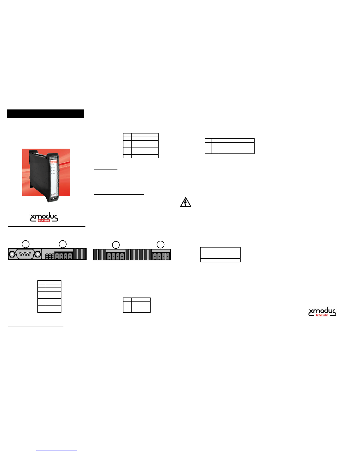
1. Connectors Top
P1: RS-232 - Serial Interface
Type: Serial V.24 (EIA/TIA-232-E).
Connector: D-SUB 9 female
Pin designation:
Switch over between RS232 and RS485:
As default, the RS232 interface is enabled. The RS485
interface will be enabled by placing a jumper (wire)
between terminal 3 of P4 and GND (P4-2).
P2: RS-422 / RS-485 Interface
Type: 2-wire, half-duplex, ¼ unit load.
Isolation: 3000 VDC (1 minute)
Termination: 390R / 390R / 220R
Pin designation:
Bus Termination:
Plugging in the jumpers J1,J2,J3 connects the bus with the
resistors for bus termination. All three jumpers should be
jointly plugged either in or out.
Sending AT commands with RS-485:
To allow sending of AT commands to a modem using the
half-duplex RS-485 interface, the command line echo must
be disabled in the modem using the ATE0 command. This
task should be made, using the RS232 interface, prior to
use the RS485 interface.
2. Connectors Bottom
P3: ISDN Interface
Type: S-Bus
Speed: 1D+1B channel
Isolation: 1500 VDC
Protection: Standard ESD
Pin designation:
P4: Power Supply
Input voltage: 9…32 V
DC
Power input: 100mA @ 9V
DC
(average)
120mA @ 9V
DC
(peak)
Pin designation:
External Reset:
Pin 4 provides an external Reset signal input. Leave open
if not used. To activate the Reset input, simply connect it to
ground (pin 2), using an external relay. After releasing the
reset input, the modem starts up again.
Do not connect the modem to the
mains power directly.
3. Front side
Led indicators:
4. Operating conditions
Environmental conditions:
Operating temp. -20°C to +70°C
Storage temp. -40°C to +85°C
Rel. humidity: ≤ 75% acc. EN60068-2-30
Protection type: IP50 acc. IEC529
Vibration: acc. EN60068-2-6
Shock : acc. EN60068-2-27
Dimensions: 120 x 101 x 23 mm
Mounting: any direction
ESD Protection:
RS232 Interface: +/- 15kV HBM
8kV IEC 61000-4-2
All other ports: +/- 15kV
IEC 61000-4-2, level 4
5. Operation
The proper and safe operation of this device assumes that
the operating instructions and the safety warnings given in
this document are read carefully.
Make sure that all cables are not live when making the
connections! Impending danger by high input voltage or
high power supply voltage!
Electrical connections are observed. The device should
only be handled by appropriately trained personnel who
xmodus swiss GmbH
Dachslernstrasse 63
CH – 8048 Zürich
Phone +41 44 438 88 82
Fax +41 44 438 88 83
e-mail:info@xmodus.ch
http://www.xmodus.ch
Document-#: XM1640S-E00-101
1 DCD
2 RXD
3 TXD
4 DTR
5 GND
6 DSR
7 RTS
8 CTS
9 RI
1 A - wire
2 B - wire
3 GND Signal
4 GND Signal
J1 390R (A)
J2 220R (A-B)
J3 390R (B)
1 TX+
2 TX3 RX+
4 RX-
1
+
DC INPUT
2
- GND
3
S Enable RS485
4
R External Reset
ON Power On
DCD Modem Connected
TXD Transmitted Data
RXD Received Data
OPERATING INSTRUCTIONS
P1 P2
A
B GND
J1 J2 J3
P3
P4
+ – S R
1 2 3 4
AT Commands, Software Documentation and Manuals:
The according Software and AT-Commands Manual should be downloaded from
our homepage which will be updated frequently. Please look at:
http://www.xmodus.ch/manuals.html
For additional documentation look also at the corresponding socket modem
manuals on our homepage. The XM1640S ISDN Terminal is based on the
AL5068S Socket Modem.
 Loading...