


On the cover picture the carbon fiber version is shown
& SUPER BLADE
BUILDING INSTRUCTIONS - OPERATING MANUAL
Nuova FULCRO Service
Via Castelleone, 9 - Costa S. Abramo - 26022 Castelverde - CR (ITALY)

Blade XL V.: 4.0 ENG - 01/05/2007
Copyright Nuova FULCRO Service
No parts of this document can be copied neither shared with any media without the author’s permission.
Nuova FULCRO Service reserves the right to modify this document according to technical improvement requirements.

INDEX
INDEX
Blade XL .........................................................................1
Features........................................................................................................ 1
Technical data .............................................................................................. 2
CHAP. 1 PARTS LIST, MATERIALS AND TOOLS LIST..............3
1.1 Warning .......................................................................................3
1.2 Components included in the kit ...................................................3
1.3 Parts needed to complete the kit, but not included ..................... 4
List of parts you will need to complete the model ......................................... 4
More options ................................................................................................. 5
1.4 Tools and materials needed (not included) to complete the kit ... 6
Tools .............................................................................................................6
Materials ....................................................................................................... 6
CHAP. 2 BUILDING INSTRUCTIONS ...........................................7
2.1 Preliminary operations ................................................................7
2.2 Fuselage .....................................................................................7
Balancing weights .........................................................................................7
Battery pack ..................................................................................................8
Servos and ON/OFF switch ..........................................................................9
Positioning battery pack and servos ............................................................. 10
Preparing and mounting servo horns............................................................ 11
2.3 V-tail ............................................................................................12
Finishing tail insertion holes.......................................................................... 12
Finishing fuselage end .................................................................................. 12
Finishing tail panels ...................................................................................... 13
Pushrods....................................................................................................... 14
Electrical connections for wing servos .......................................................... 17
Receiver........................................................................................................ 21
Antenna......................................................................................................... 23
2.4 Wing ............................................................................................24
I

Installing bushes for control horns.................................................................24
Electrical connection for the wing servos ......................................................26
Mounting servos inside the wing ...................................................................29
Wing pushrods...............................................................................................30
Servo covers..................................................................................................31
2.5 Tail connection ............................................................................32
Mounting the tail panels.................................................................................32
2.6 Nose ............................................................................................32
2.7 Connecting wing panels and tailplanes to the fuselage ..............33
CHAP. 3 MODEL SETTINGS ........................................................ 35
3.1 Servos settings ............................................................................35
Identifying the control surfaces......................................................................35
Travel values .................................................................................................36
3.2 Model balancing ..........................................................................37
CG .................................................................................................................37
Checking and correcting the CG position ......................................................37
Checking and correcting the lateral balance (both versions).........................37
How to add ballast.........................................................................................38
CHAP. 4 CONNECTIONS DIAGRAMS......................................... 39
II
Nuova FULCRO Service
BLADE XL
& SUPER BLADE
Features
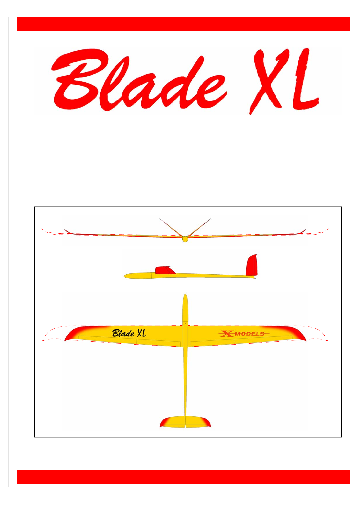
Multipurpose glider model designed to offer the best performance in almost all flying conditions,
made for who loves the speed. All moulded fiberglass carbon reinforced wing with carbon spar,
thinned RG15 (7.8%), to offer high performance and a very broad flying speed range; fiberglass
carbon reinforced fuselage suited for slope soaring and towing.
Two different wingspans are available: (XL) 2.5 m or (SUPER) ~ 3.1 m.
Fig.1: Blade XL (& SUPER BLADE).
1

X-MODELS - Blade XL & SUPER BLADE
Technical data
Wingspan (XL 2.5 / SUPER 3.1): 2500 / 3080 mm
Length: 1510 mm
Weight - XL 2.5 version (empty / in flight): about 1400 g / 2100 g
Weight - SUPER 3.1 version (empty / in flight): about 1600 g / 2300 g
Profile: RG15 mod. (7%)
Radiocomando: 6 channels
Controls: ailerons, elevator, rudder, flaps.
2

Nuova FULCRO Service
CHAP. 1 PARTS LIST, MATERIALS AND TOOLS LIST
1.1 Warning
DO NOT EXPOSE THE MODEL TO HIGH TEMPERATURES. Exposing the model (or its parts) to high temperatures, over 50
able.
1.2 Components included in the kit
COD. QT. Item Remarks
FUSO 1 fuselage fiberglass, carbon reinforced (optional, all carbon fiber)
CONO 1 front cone fiberglass (optional, all carbon fiber)
ADXL 1 right wing-panel fiberglass, carbon reinforced with aileron and flap (optional,
ASXL 1 left wing-panel fiberglass, carbon reinforced with aileron and flap (optional,
°C (example: in a car parked directly in the sun) may deform structures and make it unus-
all carbon fiber)
all carbon fiber)
CODX 1 V left tailplane balsa fiberglass sandwich with carbon spar
COSX 1 V right tailplane balsa fiberglass sandwich with carbon spar
BAIO 1 wing rod steel ~175 / ~ 235 mm - Ø 10 mm
BASE 1 servos mounting frame ply-wood
CARB 2 elevator pushrod carbon tube - length 100 cm - Ø 6 mm - hole Ø 4 mm
TCA4 1 spacer for pushrods carbon tube - length 20 cm - Ø 4 mm - hole Ø 2 mm
AMR2 8 metal pushrod length 30 cm - one tip M2 thread
UNIB 2 Nylon uniball M2 thread
VITE 2 screw length 20 mm - M2 thread
GIUN 2 ball for uniball M2 thread
FOR2 6 clevis M2 thread
DAD2 6 nut M2 thread
MPXF 2 MPX connector female plastic - 6 pin
MPXM 2 MPX connector male plastic - 6 pin
CAVS 1 wing servo cable twisted - three wires, length 2 m
CARS 2 servo hole cover 2 pair supplied to suit 4 holes
BOCC 4 threaded bush brass threaded M3
PERN 4 threaded horn brass threaded M3
3

X-MODELS - Blade XL & SUPER BLADE
Decal
If you like, you may stick the decal we supply
with the kit (see figure 2).
Fig.2: Decal “Blade XL”.
1.3 Parts needed to complete the kit, but not included
These are the parts you will need to complete the model (see “List of parts you will need to com-
plete the model”) and some you may need as option.
List of parts you will need to complete the model
To complete the model you will need the following (purchasing separately):
COD. QT. Item Remarks
SERW 4 wing servo HI-TECH HS-125MG
SERV 2 tailplane servo HI-TECH HS-322HD or HI-TECH HS-475HB
RXC6 1 receiver (+ xtal) max. dimensions: 65 x 40 x 22 mm
INTE 1 ON/OFF switch max. dimensions: 35 x 25 x 25 mm
BATT 1 rx battery pack NiCd o NiMH, 4 cells, SC size, from 1700 mAh
UNIM 4 cable with a RX (UNI) plug length: 30 cm
Note: not included in the table are glues and small parts that should obviously be present in every modeler’s house.
4
Nuova FULCRO Service
More options
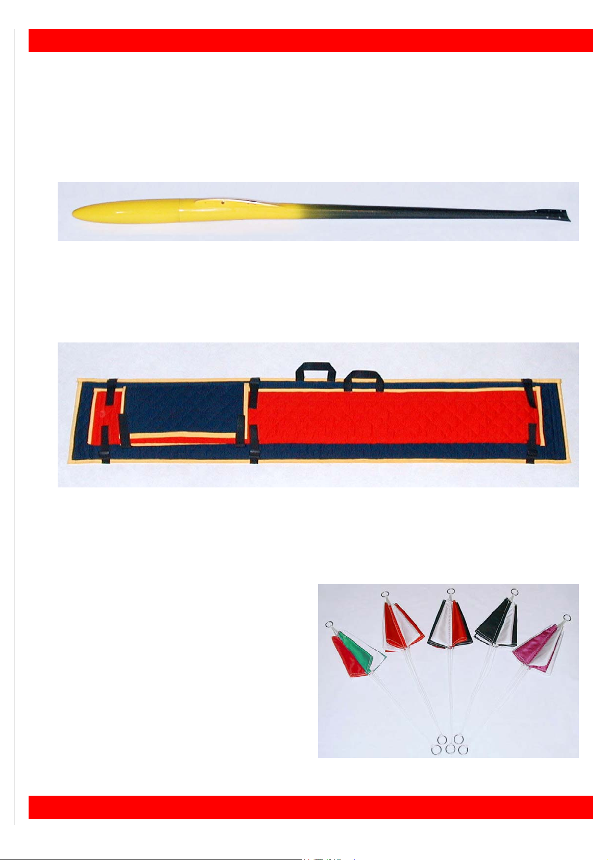
Wings and fuselage made of carbon fiber
On request, wing, tailplanes and fuselage are available completely made of carbon fiber.
The model, made in this way, offers more torsional strength and an exceptional sturdiness.
The fuselage (see figure 3) is painted like the model but with the rear part unpainted (made to
save weight without to reduce the strength).
Fig.3: Carbon fiber fuselage.
Model carrying bag
A special bag (see figure 4) it’s available, made to measure, to safely carry your model around.
Each part (wing panels, tailplanes and fuselage), take place on a separate compartment.
Fig.4: Model carrying bag.
The bag is completely hand made. Other features: quilted and trimmed cloth, lined with internal
protections in polyethylene, velcro-fastening, handles for wing and fuselage.
Towing parachute
Hand made very strong towing parachute (see
figure 5) to help in successful winch towing.
Fig.5: Towing parachute.
5

X-MODELS - Blade XL & SUPER BLADE
1.4 Tools and materials needed (not included) to complete the kit
Tools
These tools may help you while assembling the kit:
— electric drill (and various size drill bits);
— modelling knife (or scapel);
— solder + soldering iron;
— hair drier (at least 1000W);
— set of files;
— usual tools like screwdrivers, pliers, etc.;
— vernier callipers (precision 1/20 of mm);
— sandpaper P400;
— Z-Bend pliers.
Note: other tools may help you too...
Materials
To complete the model, You need the following materials:
— super-glue (CA, cyano, like Green ZAP);
— “5 minute” epoxy;
— hot glue;
— approx. 200 grams lead;
— heat shrink sleeve (diameters: 3 mm e 6 mm);
— double adhesive tape, thin;
— velcro.
Note: other materials such as paints, brushes, pencils, etc. are not mentioned.
WARNING! PAY ATTENTION TO THE SAFETY INSTRUCTIONS FOR THE USE OF ANY KIND OF GLUE OR
TOOLS.
If you should need we may supply all you need to complete your model:
Nuova Fulcro Service S.r.l.
Via Castelleone, 9 - Costa S. Abramo - 26022 Castelverde - CR (ITALY).
Tel.: 0039 0372 35138 - Fax: 0039 0372 27121
e-mail: info@fulcroservice.it
www.xmodels.it
6

Nuova FULCRO Service
CHAP. 2 BUILDING INSTRUCTIONS
In order to achieve a correct assembling of the model, we suggest to follow carefully the instructions.
2.1 Preliminary operations
Kit components control
Have a look at the components (see “PARTS LIST, MATERIALS AND TOOLS LIST” at page 3)
in order to easily identify them.
It is strongly suggested to trial fit all the parts “dry” before gluing them.
2.2 Fuselage
Inside the fuselage, the following components will be arranged:
— balancing weights;
— battery pack;
— V-tail pushrods;
— V-tail servos and ON/OFF switch;
— electrical connections for the wing servos;
— RX receiver.
Balancing weights
• Using some double adhesive tape, fasten
about 80 ~ 100 g of weights in the position
shown in figure 6; the weights have to form
a layer with no more than 10 mm of thickness (see figure 7).
Fig.6: Balancing weights position.
The layer will be used as a base for the battery
pack (see figure 7); the rest of the weights will
be added afterwards (during the model balancing) directly into the nose.
max 150 mm
Fig.7: Max. thickness of the balancing weights.
max 10 mm
7
X-MODELS - Blade XL & SUPER BLADE
Battery pack
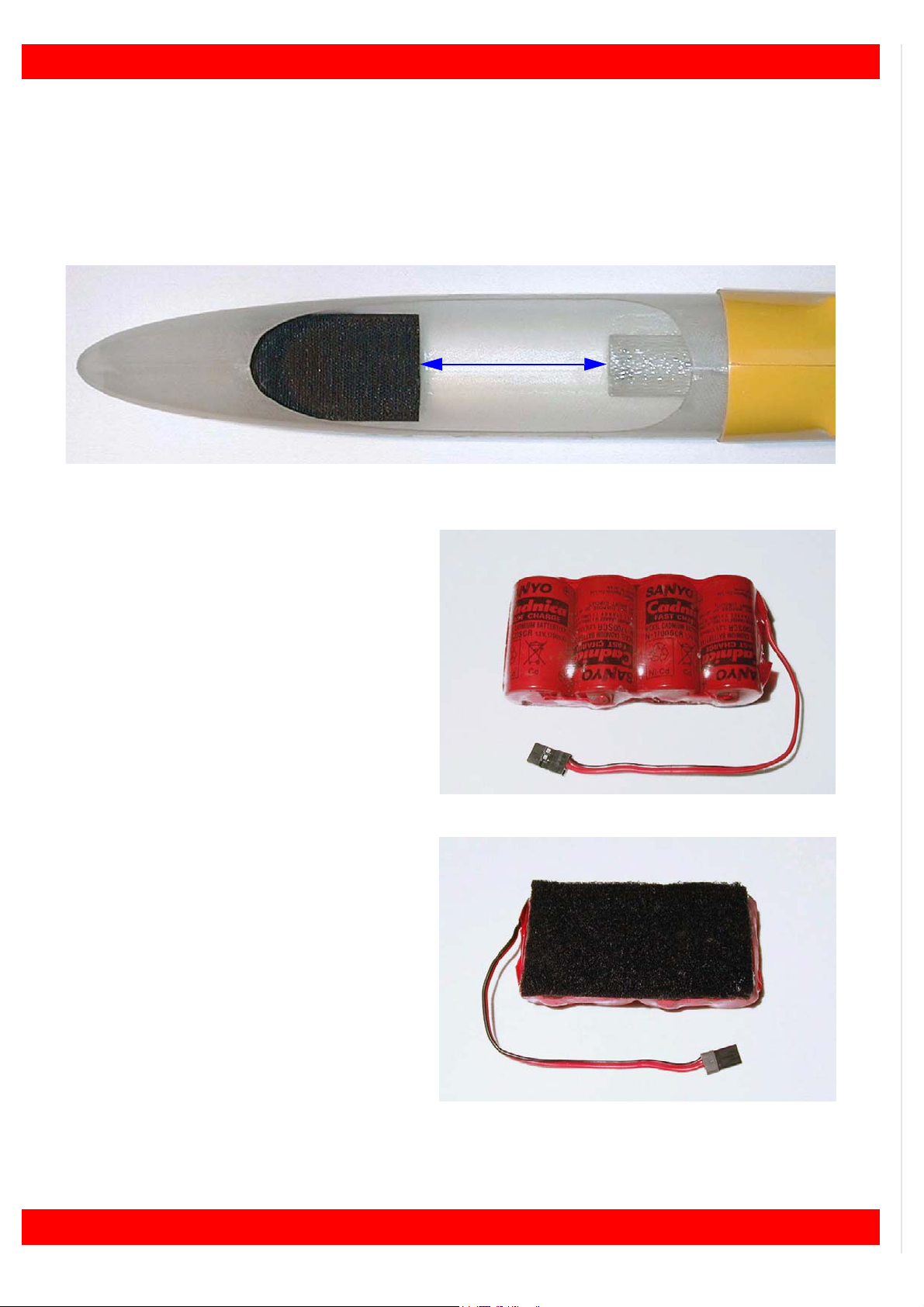
• Cover the weights of epoxy (or hot glue) in order to form a uniform layer;
• cut a strip of velcro (8 x 4 cm);
• separate the velcro soft strip from the rough one;
• position the flat surface of the rough strip directly on the base in fuselage, in the position
shown in figure 8, leaving a gap of (at least) 85 mm from the ballast tube;
85 mm
Fig.8: Rough strip of velcro in position.
• join four NC size cells in a battery pack arranged as shown in figure 9;
Note: the connector must be chosen according to the
ON/OFF switch used.
• wrap the battery pack with some heath
shrink sleeve;
Fig.9: Battery pack.
• uniformly cover of epoxy (or hot glue) one
side of the battery pack;
• position the flat surface of the soft strip directly on the glued side of the battery pack
(see figure 10);
• wait until the glue is dry;
8
Fig.10: Soft strip of velcro in position.
Nuova FULCRO Service
Servos and ON/OFF switch
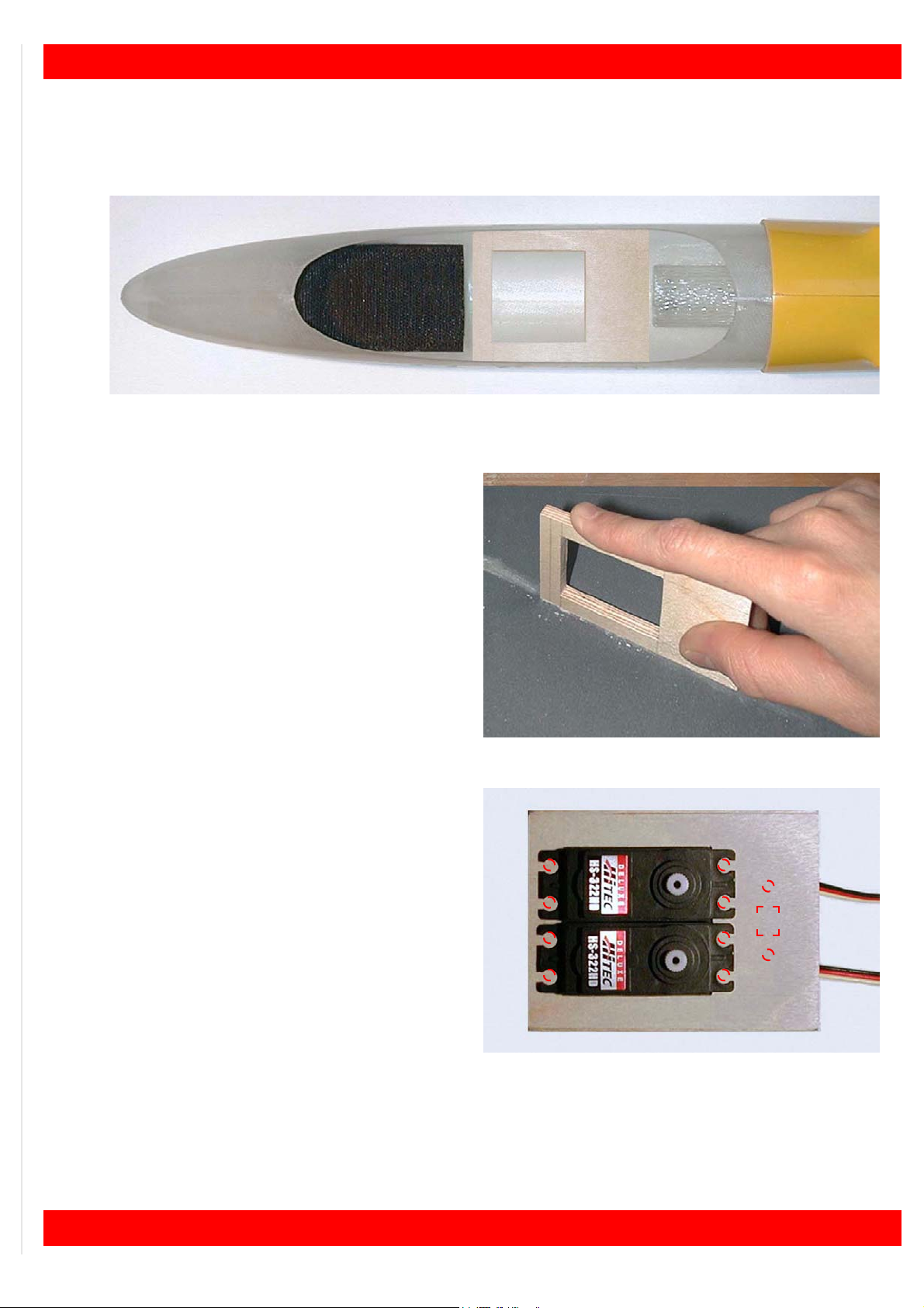
• Try to insert the servos mounting frame “BASE” in the fuselage as shown in figure 11 without
forcing too much and WITHOUT GLUING IT.
Fig.11: Position of the servos mounting frame.
If the frame doesn’t fit:
• on a flat surface, using some tape, fasten a
sheet of sandpaper (P400);
• using the sandpaper, finish the edges of the
mounting frame (see figure 12);
• try to insert the frame once again (always
WITHOUT GLUING IT) until it doesn’t fit correctly;
• remove the frame;
Fig.12: Smooth the edges of the mounting frame.
• try to mount the two servos “SERV” on the
frame as shown in figure 13 without forcing.
If the servos doesn’t fit
• using a file, adjust the housing and try again.
Once having inserted servos:
• using a pencil, mark the position of the servos fixing holes;
Fig.13: Position of the servos.
• using a calliper, take the dimensions of the switch;
• using a pencil, draw the shape of the ON/OFF switch lever movement (seen from top) and the
position of the holes for the fastening screws;
• remove the two servos;
9

X-MODELS - Blade XL & SUPER BLADE
• drill 1.5 mm diameter hole on the marked
points (see figure 14);
• using a knife, make the ON/OFF switch
housing;
Fig.14: Drill the marked points.
• mount the two servos on the frame as
shown in (see figure 15) and fasten with the
proper screws;
• mount also the ON/OFF switch;
• check that ON and OFF markings truly correspond to the status “switched ON” and
“switched OFF”;
• check the correct travel of the ON/OFF
switch lever;
• fasten the switch using the proper screws.
Fig.15: Servos and ON/OFF switch.
Positioning battery pack and servos
• Insert the battery pack as
shown in figure 16;
Fig.16: Battery pack in position.
• position the servos mounting frame in order to remove freely the battery pack (see figure 17);
10
Fig.17: Frame with servos and ON/OFF switch in position.

Preparing and mounting servo horns
Preparing horns
For each servo horn:
• Using side cutters, cut the servo horns in
surplus (see figure 18).
Fig.18: Cut the servo horns in surplus.
Nuova FULCRO Service
• drill 1.5 mm diameter hole in order to widen
the servo horn hole (see figure 19).
Fig.19: Widen the servo horn hole.
Mounting horns
• Mount the two servo horns as shown in fig-
ure 20 and fasten with the proper screws.
Fig.20: Mounting servos horns.
11

X-MODELS - Blade XL & SUPER BLADE
2.3 V-tail
Finishing tail insertion holes
• Using a drill bit 6 mm diameter (larger than
the holes), trim exceeding metal edges from
the tail insertion holes (see figure 21);
Fig.21: Trim exceeding metal edges.
Finishing fuselage end
• Using a knife, modify the final part of the fuselage (see figure 22) in order to avoid any
interference with the servo pushrods;
Fig.22: Adjusting the end of the fuselage.
• using a file or some sandpaper, finish the
edge up to obtain the shape shown in figure
23.
The picture shows the difference from the initial
look and the final one (obviously both sides
must be molded in the same way).
Fig.23: Comparing the initial and the final look.
12

Finishing tail panels
Tail panels support pins
• Using a pair of pliers, bend a little bit the two
tail connection pins in order to make them
slightly diverging (see figure 25); this opera-
tion will avoid the tail to slip out from its supports during the flight;
Fig.24: Bend the two pins.
• using a sharp knife, remove the glue in excess from the root of the pins (see figure
25);
Nuova FULCRO Service
Fig.25: Remove the glue in excess.
Pushrods connections
• Fully fasten the ball “GIUN” on the screw
“VITE” (see figure 26);
Fig.26: Fasten the ball on the screw.
• screw the ball connector into the tail panel
unit (see figure 27);
• repeat the operation for the other tail panel;
GIUN VITE
Fig.27: Fastening the group screw-ball.
13

X-MODELS - Blade XL & SUPER BLADE
Pushrods
• using side cutters, cut two metal pushrods
“AMR2” at a length of 100 mm;
• cut the other two metal pushrods “AMR2” at
a length of 150 mm;
• using side cutters, carefully make some
dents in the (non threaded part of the) rod
“AMR2”, for a length of 5 cm, in order to in-
crease the adhesion of the epoxy (see figure
28), but careful not to cut through or weaken
it the wire rod;
Fig.28: Making some dents on the rod.
• using a little saw, cut the carbon tube “TCA4” in four parts 40 ~ 50 mm length each one;
• insert one of the two 100 mm length pushrod “AMR2” (from the NON threaded side) into the
carbon spacer “TCA4”;
• glue the carbon spacer
“TCA4” in the position
shown in figure 29;
Fig.29: Front pushrod group.
• screw the nut “DAD2” and a clevis “FOR2” to the 100 mm pushrod “AMR2”;
• repeat the operation in order to make two identical front pushrod groups;
• insert one of the two 150 mm length pushrod “AMR2” (from the NON threaded side) into the
carbon spacer “TCA4”;
• glue the carbon spacer “TCA4” in the position shown in figure 30;
FOR2
DAD2
AMR2TCA4 UNIB
AMR2
5 cm
TCA4
Fig.30: Rear pushrod group.
• screw a ball link socket “UNIB” to the 150 mm pushrods “AMR2”;
• repeat the operation in order to make two identical rear pushrod groups;
• using a saw, cut the two carbon elevator pushrods “CARB” at 1 m length each one;
• insert and glue the rear pushrod groups into the elevator pushrods “CARB” (see figure 31);
Fig.31: Insert and glue the rear pushrod groups.
14

Nuova FULCRO Service
• insert the front pushrod groups into the elevator pushrods “CARB” WITHOUT GLUING THEM
(see figure 32);
Fig.32: Inserting front pushrod groups (without gluing them).
• insert the two complete pushrod groups into
the fuselage (see figure 33);
Fig.33: Inserting a pushrod group into the fuselage.
• insert the tailplanes into the proper housings
(see figure 34);
Fig.34: Inserting tailplanes.
• temporary clip the ball socket ends “GIUN”
to the ball connectors “UNIB” (see figure
35);
Fig.35: Clip the ball socket ends to the connectors.
15

X-MODELS - Blade XL & SUPER BLADE
• using some masking tape, keep the V-tail
movable control surfaces aligned (see figure
36);
Fig.36: Keeping control surfaces aligned.
• connect the clevises to the servos horns in
fuselage;
• using a fibre-tip pen, mark the position of the
metal pushrods (see figure 37);
• remove the front pushrod groups from the
carbon pushrods.
Fig.37: Mark the metal pushrod.
For each front pushrod group:
• spread some “5 minute” epoxy on the carbon spacer of the front pushrod group;
• insert the pushrod group into the carbon
pushrod (see figure 38) up to the marked
point;
• before that the epoxy drys, clip the clevis to
the servo horn;
• wait until the glue is dry;
• repeat the operation with the other front
pushrod group;
• remove the masking tape from the tailplanes;
Fig.38: Insert the front pushrod group.
• remove the ball socket ends “UNIB” from the ball connectors “GIUN”;
• remove the tailplanes.
16

Nuova FULCRO Service
Electrical connections for wing servos
The electrical connection between wing servos and receiver is made with a set of connectors like
the ones shown in figure 39.
• Take the external dimensions of the “MPXF”
connector.
MPXF
Fig.39: Wing servos connectors set.
Preparing electrical connections
Each RX connector (see figure 40) have 3 wires: signal (~), positive (+)
and mass (-).
Fig.40: Signal (~), positive (+) and mass (-).
• Before soldering, insert the free tip of every wire, into a 15 mm long heat shrink sleeve of suitable section;
• solder wires of the cables “UNIM” to the connectors “MPXF” as shown in figure 41 and cover
with the heat shrink sleeves.
MPXM
~
+
_
+
~
~
_
Fig.41: Connection diagram from wing servos to receiver.
+
~
~
_
17

X-MODELS - Blade XL & SUPER BLADE
Holes for the wing servos connections
• At a distance of 40 mm from the alignment hole (see figure 42), using a knife (with a well
sharpened blade), make a hole having the same dimensions of the “MPXF”connector;
40 mm
Fig.42: Position of the hole.
• using a flat file, finish the shape of the hole
(see figure 43) continuously checking the di-
mensions;
• on the other side as well repeating the measurements and distances (in order to obtain
two identical holes in perfect alignment).
Fig.43: Finish the shape of the hole.
Preparing the wing root holes
• Insert the wing rod “BAIO” into its housing
(see figure 44);
Fig.44: Insert the wing rod into its housing.
18

• insert a wing-panel (see figure 45);
Fig.45: Inserting a wing-panel.
• using a pencil lead or a metal scriber (at
least 6 cm long), mark the shape on the
wing root tracing it from the hole already
done (see figure 46);
Nuova FULCRO Service
Fig.46: Trace the contour of the hole.
• remove the wing-panel and trace better the
contour (see figure 47);
• repeat the operation also for the other wingpanel.
Fig.47: Trace better the contour.
How to finish this hole on the wing-panels will be described later.
19

X-MODELS - Blade XL & SUPER BLADE
Preparing electrical connections
• Insert the cables (from the side of the RX
connectors) into the hole made in the fuselage (see figure 48);
Fig.48: Inserting RX connectors.
• insert the cables up to the socket “MPXF”
(see figure 49);
Fig.49: Inserting a cable up to the socket.
• spread some epoxy around the socket
“MPXF” and insert it into the proper housing
in the fuselage as shown in (see figure 50);
• wait until the glue is dry;
Fig.50: Socket in position.
• repeat the operation also on the other side.
20

Nuova FULCRO Service
Receiver
The receiver must be protected against possible shocks due to hard landings:
• cut two strips of polyethylene (5 mm thick)
and, using some tape, fasten them, over
and under the RX (see figure 51);
Fig.51: One strip over and the other under the RX.
• drill 3 mm diameter hole in the fuselage in
the position shown in figure 52;
• place a round servo grommet into the hole,
in order to avoid any damage to the antenna’s wire;
Fig.52: Antenna’s hole position.
• let the wire pass through the hole as shown
in figure 53;
Fig.53: Thread the antenna’s wire through the hole.
25 mm
The final positioning of the antenna will be shown later.
21

X-MODELS - Blade XL & SUPER BLADE
• insert the receiver “RXC6” into the fuselage,
behind servos, as shown in figure 54;
Fig.54: Positioning the receiver.
• position the receiver as shown in figure 55;
Fig.55: Final position of the receiver.
• plug the RX plugs to the receiver according
to the diagram in figure 88 at page 39;
• using a plastic hose-tie, gather all the RX
cables (without tighten too much) in order to
avoid any interference with the servo pushrods (see figure 56);
Fig.56: Plug the RX plugs to the receiver.
22

Nuova FULCRO Service
In figure 57 is shown the final look of the fuselage internal components.
Fig.57: Final look of the fuselage internal components.
Antenna
Because of the fuselage’s reinforcements and the elevator push-rods, both in carbon fiber, we
suggest to leave the antenna outside the fuselage.
For the best reception signal, the position we recommend is the one shown in figure 58.
Fig.58: Antenna’s (recommended) position.
Anyway, we recommend to equip your own model with a long range high quality receiver and
carefully to check the long range behavior with a field test.
23

X-MODELS - Blade XL & SUPER BLADE
2.4 Wing
The wing is divided in two panels, each one equipped with aileron and flap.
Flaps and ailerons servos are fitted into the wings. For this reason, each wing panel is fitted with
two rectangular housings where servos can be mounted. The use of flat servos (max. 13 mm -
better 11) with high torque (at least 20 Newton/centimeter) is foreseen.
The assembling procedure is identical (as in a mirror), for each wing panel.
Installing bushes for control horns
• Drill 4mm diameter holes on ailerons and flaps in the points shown in figure 59;
Fig.59: Position of the bushes.
WARNING! the center of the hole must be, at
least, 10 mm away from the leading edge of
the movable surfaces (see figure 60);
• using a file (about 5mm diameter, round
section), finish the holes;
Fig.60: Distance of the hole.
• insert the threaded bushes “BOCC” in their
holes from the top surface (see figure 61);
• with a drop of cyano or epoxy glue the bushes.
+
10 mm
BOCC
+
24
Fig.61: Bush in position (wing seen from top).

Holes for wing servos connection
• Using a drill (3 mm diameter), make some
holes inside the marked part (see figure 62);
Fig.62: Make some holes inside the marked part.
• using a knife (with a well sharpened blade)
remove all the material inside the wing in order to make enough space for the connector
(see figure 63);
Nuova FULCRO Service
Fig.63: Remove the exceeding part.
• to check the precision of the hole, temporary
insert the wing-panel and, looking through
the hole made into the fuselage, locate the
part to remove (see figure 64).
Note: a torch (or strong light source), shone directly
through the fuselage aperture, will show up the part of
the matching aperture that needs adjusting.
Fig.64: Observing through the hole.
25

X-MODELS - Blade XL & SUPER BLADE
Electrical connection for the wing servos
The the wing servos connection needs just four wires to connect following the diagram shown in
figure 65.
+
~
~
_
Fig.65: Connection diagram for the wing servos (the same for the other wing).
• Insert the four wires into the wing up to the servos housings.
The positive (red) wire of flap servo can be connected with the same wire coming from the aileron servo; the same thing can be done also with the negative (black or other dark color) wire, but
(ATTENTION!) this can’t be done between the signal (orange or yellow) wires: the signal wires
must be always kept separate; in this way, only four wires (positive, servo flap signal, aileron servo signal, negative) will arrive to the connector “MPXM”.
Connectors
• Before soldering wires to the connector “MPXM”, insert the free tip of every wire into a 15 mm
long heat shrink sleeve of suitable section;
• solder the wires to the connector “MPXM” as shown in the diagram in figure 65;
• let every heat shrink sleeve slide on its soldering;
• using a hair drier (at least 1500W), direct the (very hot) air blow over the sleeves and let them
mould on the solderings.
Caution! When shrinking sleeves over joined wires, do not allow the hot air to `blast` over the wing or control surfaces - you will irreparably damage the wing!
• widen the rectangular hole on the wing root
until the connector will not perfectly fit;
• spread a little bit of epoxy around the connector and fasten it in the position shown in
figure 66;
• let the glue dry and repeat also on the other
side.
26
Fig.66: Connector in position.

Nuova FULCRO Service
Flap servo
• Using side cutters, remove the RX connector of the servo;
• cut and strip, for a length of about 10 mm, the three wires coming from servo;
• strip the black and the red wire coming from
the wing for a length of 10 mm, but, WITHOUT CUTTING THEM;
• before soldering, insert the free tip of every
wire into a 15 mm long heat shrink sleeve of
suitable section;
• solder the end of the red wire, coming from
servo, to the skeined red wire coming from
the wing and do the same soldering the
black (or dark) wire, coming from servo, to
the black one coming from the wing (see fig-
ure 67);
Fig.67: Flap servo connections.
• cut and strip, for a length of about 10 mm, the end of the orange wire coming from the wing
and solder it to the end of the signal wire coming from servo; but, don’t touch the other sig-
nal wire (the one for the aileron);
• let every heat shrink sleeve slide on its soldering;
• using a hair drier (at least 1000W), direct the (very hot) air blow over the sleeves and let them
mould on the solderings.
Caution! - when shrinking sleeves over joined wires, do not allow the hot air to `blast` over the wing or control surfaces - you will irreparably damage the wing!
Aileron servo
• Using side cutters, remove the RX connector of the servo;
• cut and strip, for a length of about 10 mm, the end of all the three wires coming from servo;
• cut and strip, for a length of about 10 mm, the end of all the three wires coming from the wing;
• before soldering, insert the free tip of every wire into a 15 mm long heat shrink sleeve of suitable section;
• solder the end of the orange wire coming
from the wing, to the end of the same wire
coming from the servo; solder the end of the
red wire coming from the wing to the red one
coming from the servo and do the same soldering the black (or dark) wire, coming from
servo, to the black one coming from the win
(see figure 68);
• let every heat shrink sleeve slide on its soldering;
Fig.68: Aileron servo connection.
• using a hair drier (at least 1000W), direct the (very hot) air blow over the sleeves and let them
mould on the solderings.
Caution! - when shrinking sleeves over joined wires, do not allow the hot air to `blast` over the wing or control surfaces - you will irreparably damage the wing!
27

X-MODELS - Blade XL & SUPER BLADE
Servos test
Before to mount the wing servos, will be better to check the connections:
• connect servos (and ON/OFF switch) to the receiver following the diagram shown in figure 88
at page 39;
• check that the ON/OFF switch is in position OFF, then plug the battery pack;
• switch on the transmitter before, then the receiver;
• check the correct link of each servo to the transmitter;
• adjust the central position of the servo horns;
Note: eventually, the servos horn central position can be mechanically adjusted just removing and reinserting the
horn in a different position.
• switch off the receiver before, then the transmitter.
Further adjustments will be done during the model settings.
28

Mounting servos inside the wing
For each wing servo “SERW”:
• shorten the horn of (at least) two holes (see
figure 69);
Fig.69: Shorten the horn.
• fasten the horn to the servo;
• remove protection film and apply the double
adhesive plate to the servo (see figure 70);
Note: we suggest to spread some “five minutes” epoxy
in order to better glue the servo to the wing”.
Nuova FULCRO Service
Fig.70: Apply the double adhesive plate.
• insert the servo into the housing (the horn
must be on the EXTERNAL SIDE OF THE
WING and towards the trailing edge (see fig-
ure 71);
• press the servo to fasten it.
Fig.71: Servo housing.
29

X-MODELS - Blade XL & SUPER BLADE
Wing pushrods
For each wing servo:
• screw the nut “DAD2” and the clevis “FOR2”
on the threaded pushrod “AMR2”;
Fig.72: Pushrod, nut and clevis.
• screw the threaded horn “PERN”in the bush
“BOCC”;
• connect (temporary) the clevis to the horn;
• using a fibre-tip pen, mark the distance from
the servo horn and the threaded horn (see
figure 73);
• remove the clevis from the threaded horn;
Fig.73: Mark the distance on the pushrod.
FOR2DAD2AMR2
BOCC
PERN
• using the Z pliers, make a “Z” bend on the
pushrod “AMR2”: the marked point must
correspond to the reference point on the pliers as shown in figure 74;
• using side cutters, cut the pushrod about
half centimeter behind the Z bend;
Fig.74: Bend the pushrod.
• insert the Z bent pushrod in the servo horn
(see figure 75) and connect the clevis to the
control horn.
Fig.75: Insert the pushrod and connect the clevis.
30

Nuova FULCRO Service
Servo covers
The wing servo covers are made from the shapes “CARS”.
From every shape, two covers can be made (left and right):
• take the distance (1) from the external edge
of the servo housing and the servo horn
(see figure 76);
• take the dimensions (2 and 3) of the external
servo housing edges;
1
3
Fig.76: Take the dimensions.
2
• taking as reference the center of a bulge of
the shape “CARS” (see figure 77), carry the
taken measure (1) from the external edge of
the servo housing and the servo horn;
1
• from that point, using a pencil, draw a rectangle with the same dimensions (2 and 3) of
the external housing edge taken before;
2
3
Fig.77: Shape for two servo covers (left and right).
• symmetrically, make the other servo cover from the other half of the shape;
• repeat the procedure for the other shape in order to obtain the four servo covers required;
• using a file, finish every cover fitting it to the
corresponding housing;
• using some thin double adhesive tape, apply
the inner covers (see figure 78).
Note: the outer covers will be applied to the wing just after the lateral model balancing that will be described later.
Fig.78: Servo cover in position.
31

X-MODELS - Blade XL & SUPER BLADE
2.5 Tail connection
Mounting the tail panels
• Mount the tail panels as shown in figure 79;
Fig.79: Mounting tail panels.
• insert the ball link sockets “GIUN” to the ball
joints “UNIB” (see figure 80).
Fig.80: Inserting the sockets to the ball joints.
2.6 Nose
• Install the nose cone “CONO” and adjust the mating end to match the joint to the fuselage
(see figure 81);
• check that the servo will move freely also with the nose cone on.
Fig.81: Installing the nose cone.
32

Nuova FULCRO Service
2.7 Connecting wing panels and tailplanes to the fuselage
• Insert the wing rod “BAIO” into its housing
(see figure 82);
Fig.82: Insert the wing rod.
• insert the wing rod in the hole on the root of
the wing (see figure 83);
• insert the wing completely, fitting the electrical connections and the alignment pin;
• repeat the operation also for the other wing
panel.
Fig.83: Insert the wing panel.
33

X-MODELS - Blade XL & SUPER BLADE34Nuova FULCRO Service

CHAP. 3 MODEL SETTINGS
3.1 Servos settings
Identifying the control surfaces
Refer to figure 84:
— ailerons 1 and 2 (roll);
— flap 3 and 4 (camber changing, crow brake);
— tailplanes 5 and 6 (pitch - yaw).
1
3
5
Fig.84: Control travel.
2
4
6
35

X-MODELS - Blade XL & SUPER BLADE
Travel values
These are suggested values, found during our test flights. Just consider these a starting point
and feel free to modify the travel values according to your flying skill, style, flying area, etc.
Ailerons
Up ............................................ min. 10 mm, max. 14 mm;
Down ........................................ min. 8 mm, max. 10 mm.
Note: you may reduce differential for aerobatic flights.
Flap
Up ............................................ 2 mm;
Down ........................................ 4 mm.
Note: value good when the flaps are used by themselves, if used in mix with aileron to change camber, please refer
to FLAP to AILERON mix set up.
V- tail
Up ............................................ min. 8, max. 10 mm;
Down ........................................ min. 8, max. 10 mm.
Note: measurement taken at the fuselage side.
Special mix
If you have a computer radio you may take advantage of it and use also the following mix:
Aileron to Rudder (Combi Mix): .... 30%.
Flap to Aileron: ............................. up (speed) 2 mm / down (thermal) 2 mm;
Elevator to flap: ............................ up 5 mm / down 5 mm;
Aileron to flap: .............................. up (speed) 1 mm / down (thermal) 1.5 mm;
Butterfly: ....................................... aileron up 20 mm, flap down 30 mm, elevator down 2 mm
(you will have to try the butterfly at a safe height the first time,
to check for the right travel value).
36

Nuova FULCRO Service
3.2 Model balancing
CG
The CG of the model must be placed at 83 ~ 88 mm from the wing leading edge at the wing root
(see figure 86).
83 ~ 88 mm
Fig.85: CG position.
Note: You may in a second time move it a little backwards if you feel (and if you are a real good pilot...).
Checking and correcting the CG position
• Mark with a piece of tape the CG position under the wing and hold the model with your fingers:
the model must stay level;
• remove or add lead to front until satisfied.
Note: the model must be complete with all his part including the nose cover during the CG check.
• once positioned the CG in the correct point, secure the lead used to balance, in the nose, so it
cannot move again.
Checking and correcting the lateral balance (both versions)
Before to apply the outer servo covers, we recommend to check (and eventually correct) the
model lateral balancing.
Checking
• Lay the model on a flat hard surface;
• try to keep the model flat rising the wing that is in touch with the ground;
37

X-MODELS - Blade XL & SUPER BLADE
• gently leave the model alone (see figure 86);
Fig.86: Checking for lateral balance.
• repeat this more times.
Correcting
If the same wing half drops all the times:
• add some lead pellet to the lighter wing (you can place the lead in the servo hole) until satisfied (usually a few grams do the job);
• repeat the test (see “Checking” at page 37).
If the wings halves are dropping randomly, the model is ok; in this case:
• apply the servo covers (see “Servo covers” at page 31).
How to add ballast
Flying in the wind (dynamic fly) requires the addition of ballast in order to increase the stability of
the model in turbulent air.
The ballast must be put around the CG (in this way the CG will not change too much); for this
reason, the carbon fuselage has been equipped (in its lower part) with a cylindric housing for the
ballast (see figure 87) approx. 280 long and with a diameter of 27.5 mm.
The housing can lodge ballast for an amount of approx. 1500 grams. The best shape for the ballast is one or more crop ends (approx. 25 mm long) obtained from a lead bar of proper section
(approx. 30 mm).
A less amount of lead (es. 500 g.) must be
firmly inserted in the center of the tube; for this
reason, wooden spacers must be inserted into
the tube either in front than behind the lead.
When fitting single ballast `slugs`, and not filling up
ballast tube fully, ensure that the wooden spacers
are positioned either side of ballast slugs, to keep
the ballast in the centre of the ballast tube and on
the CG!
Fig.87: Ballast tube.
Once inserted the ballast, we recommend to accurately check the CG position.
38

Nuova FULCRO Service
CHAP. 4 CONNECTIONS DIAGRAMS
Here are shown the complete connection diagrams (with battery pack, ON/OFF switch, receiver
and servos) for each version of the model.
Note: the connection to the receiver outputs depends from the radio control type and receiver you are using.
OFF
ON
+
~
~
_
Fig.88: Electrical connections.
+
~
~
_
39
 Loading...