

Page 1

WLAN 11g Broadband Router
User Manual
Page 2

2
This product is in compliance w ith the essential requ irements and other
relevant provisions of the R&TTE directive 1999/5/EC.
Product Nam e: X-Micro WLAN 11 g Broadband Router
Model Name : XWL-11GRIX
MAX. OUT POWER
COUNTRY CHANNELS
INDOOR OUTDOOR
Spain 2400-2483.5 MHz 1-13 < 100 mW EIRP < 100 mW EIRP
France 2400-2454 MHz 1-8 < 100 mW EI RP < 100 mW EIRP
France 2454-2483.5 MHz 9-13 < 100 mW EI RP < 10 mW EI RP
Italy 2400-2483.5 MHz 1-13 < 100 mW EIRP < 100 mW EIRP
UK 2400-2483.5 MHz 1-13 < 100 mW EIRP < 100 mW EIRP
Netherlands 2400-2483.5 MHz 1-13 < 100 mW EIRP < 100 mW EIRP
Germany 2400-2483.5 MHz 1-13 < 100 mW EIRP < 100 mW EIRP
Austria 2400-2483.5 MHz 1-13 < 100 mW EIRP < 100 mW EIRP
Belgium 2400-2483.5 MHz 1-13 < 100 mW EIRP < 100 mW EIRP
Switzerland 2400-2483.5 MHz 1-13 < 100 mW EIRP < 100 mW EIRP
Luxemburg 2400-2483.5 MHz 1-13 < 100 mW EIRP < 100 mW EIRP
Ireland 2400-2483.5 MHz 1-13 < 100 mW EIRP < 100 mW EIRP
Portugal 2400-2483.5 MHz 1-13 < 100 mW EIRP < 100 mW EIRP
Norway 2400-2483.5 MHz 1-13 < 100 mW EIRP < 100 mW EIRP
Denmark 2400-2483.5 MHz 1-13 < 100 mW EIRP < 100 mW EIRP
Finland 2400-2483.5 MH z 1-13 < 100 mW EIRP < 100 mW EIRP
Iceland 2400-2483.5 MHz 1-13 < 100 mW EIRP < 100 mW EIRP
Greece 2400-2483.5 M Hz 1-13 < 100 mW EIRP < 100 mW EIRP
Lichtenstein 2400-2483.5 MH z 1-13 < 100 mW EIRP < 100 mW EIRP
Sweden 2400-2483.5 MHz 1-13 < 100 mW EIRP < 100 mW EIRP
Page 3

3
FCC INFORMATION
FCC R adiation Exposu re Statem en t
This equipment complies with FCC radiation exposure limits set forth for an
uncontrolled environment. This equipment should be installed and operated with
minimum distance 20cm between the radiator & your bo dy. This transmitter must
not be co-located or operating in conjunction with any other antenna or transmitter.
The equipment has been tested and found to comply with the limits for a Class
B Digital Device, p ursuant to part 15 o f the FCC Ru les. These limits are des igned
to provide reasonable protection against harmful interference in a residential
installation. This equipment generates, uses and can radiate radio frequency
energy and, if not installed and used in accordance with the instruction, may cause
harmful interference to radio communication. However, there is no grantee that
interference will not occur in a particular installation. If this equipment dose cause
harmful interference t o radio or television re ception, which can be determined by
turning the equipment off and on, the user is encouraged to try to correct the
interference by one or more of the following measures:
--Reorient or relocate the receiving antenna.
--Increase the separation between the equipment and receiver.
--Connect the equipment into an outlet on a c ircuit different from that to which the
receiver is connected.
--Consult the dealer or an experienced radio/TV technician for help.
Notice: The Part 15 radio device operates on a non-interference basis with other
devices operating at this frequency. Any changes or modification not expressly
approved by the party responsible could void the user’s authority to operate the
device.
REGULA TOR Y INFORMATION
X-Micro WLAN 11g Broadband Router must be installed and used in strict
accordance with the instructions. This device complies with the following radio
frequency and safety standards.
USA - Federal Communications Commission (FCC)
This device complies with Part 15 of FCC Rules. Operation is subject to the
following two conditions:
1. This device may not cause harmful interference.
2. This device must accept any interference that may cause undesired operation.
Page 4

4
Copyright
Copyright 200 4 by X-Mic ro Tec hnology Corp., A ll rights reserv ed. No part of
this publication may be reproduced, transmitted, transcribed, stored in a
retriev al s ystem , or tra nslated int o any l anguage or com puter langua ge, in
any form or by any means, electronic, mechanical, magnetic, optical,
chemical, manual or otherwise, without the prior written permission of
X-Micro Technol ogy Corp .
Disclaimer
X-Micro Technology Corp. makes no representations or warranties, either
expressed or implied, with respect to the contents hereof and specifically
disclaims any warranties, merchantability or fitness for any particular
purpose. A ny software d escribed in t his m anual is sold or licensed " as is".
Should the programs prove defective following their purchase, the buyer
(and not th is company, its distr ibutor, or its dealer) assumes the e ntire cost
of all necessary servicing, repair, and any incidental or consequential
damages resulting from any defect in the software. Further, X-Micro
Technology C orp., reserv es the rig ht to revis e this p ublication and t o make
changes fr om time to t ime in the co ntents hereof without obl igation to notify
any person of suc h revision or cha nge.
All brand and product names mentioned in this manual are trademarks
and/or registered trademarks of their respective holders.
Page 5

5
Contents
1. OVER VIEW.... ........................... .................. ........... ................... ................... .......6
1.1 Product Feature..........................................................................................6
1.2 System Requirements................................................................................ 6
1.3 Appl icati ons... ........ ..... ........ ...... ........ ..... ........ ..... ........ ...... ........ ..... ........ .....6
2. Installing Your Router...........................................................................................7
2.1 Installation Instructions............................................................................... 7
3. Prep aring Your Network.......... ................... .................. ........................................8
3.1 Configuring Windows for IP Networking.....................................................8
3.2 To Configure Windows to Receive Dynamic IP Address:............................8
3.3 Collecting ISP Information........................................................................10
4. Basic Fu nctions.............................................................. ................... ................11
4.1 To Open the Web-based Administration Tool:...........................................11
4.2 Setup........................................................................................................13
4.3 Global Address.........................................................................................17
4.4. Wirel ess........ ..... ... ..... ... ..... ... ..... ... ..... ... ..... ... ..... ... ..... ... ..... ... ...... .. ...... .. ...20
4.5 Tools................................................. .................. ................... ...................29
4.6 S tatus .......................................... ........................................... ...................33
4.7 DHCP.......................................................................................................36
4.8 Log........................................................................................................... 38
4.9 S tati stics..... ................... ................... .................. ........... ................... ........41
5. Advanc ed Functi on............ .......... ........ ........... ........ ........... ........ .......... ......... .....43
5.1. To T oggle between Basic Functions and Advanced Functions:................43
5.2 Virtual Servers..........................................................................................44
5.3 Filters........................................................................................................47
5.4 IP/URL Block............................................................................................51
5.5 S p ecial Apps.......................... ........... .................. ................... ...................54
5.6 DMZ Host.................................................................................................58
5.7 MAC Clone...............................................................................................60
5.8 Dynamic DNS...........................................................................................61
5.9 Proxy DNS ................................................................................................63
5.10 SNMP.....................................................................................................65
5.11 Static Routi ng.... ...... .. ...... ..... ... ..... ... ..... ... ..... ... ..... ... ..... ... ..... ... ..... ... ..... ...68
Page 6

6
1. OVERVIEW
1.1 Product Feature
Compliance wit h IEEE 802 .11g and 802.11b standards
Highly efficient design mechanism to provide unbeatable performance
Strong network s ecurity with WEP and 802.1X e ncr ypt io n
Achieving data rate up to 54Mbps for 802.11g and 11Mbps for 802.11b with
wide range coverage; high performance to deliver up to 54Mbps raw data
rate for 802.11g
Quick and easy setup with Web- based management utility
1.2 System Requirements
Windows 98, 98SE, Millennium Edition (ME), 2000 and XP operating
systems
Microsoft Internet Explorer 5.5 or higher
DSL/ Cable Modem Broa dband Internet c onnection and ISP account
PCs eq uipped wi th 10 Mbps or 1 0/10 0 Mb ps Ether net c onne ction t o support
TCP/IP protocol
One CD-ROM driver
1.3 Applications
Home SOHO networking for device sharing and wireless multimedia
Wireless of fic e pr ovides a w ider range for home and SOHO Ethernet
Enables wireles s building-to-b uilding data communication
Built-in infrastruc ture mode
Router provides ideal solution for:
Temporary LANs for scenarios such as trade-exhibitions and meetings
Enables LAN adaptability to frequently changing e nvironments
Enables rem ote acc ess to cor porate networ k inform ation, for exam p le e-m ai l
and company home page
Page 7

7
2. Installing Your Router
In this chapter, you’ll lear n how to connect your r outer.
2.1 Installation Instructions
To Connect the Router:
2.1.1. Make sure all equipments are turned off, i ncluding the ro uter, De sktop
or Laptop PCs, the cable and DSL m odem , and so on.
2.1.2. Connect the WAN Port of t he router to the cable and DSL m odem,
Ethernet Server or t he hub.
2.1.3. Connect your client PCs to the LAN Ports.
2.1.4. Connect the Power Adaptor (5VDC, 1.2A) to the power jack of the
router and plug t he power cable into t he out let .
2.1.5. Turn on our PCs.
Page 8
8
3. Preparing Your Net work
In this chapter, you’ll learn what to do before configuring your
network.
Before configur ing your router, you need set up the computers
in your netw ork f or TCP/IP networki ng and collect r el evant ISP
informati on if necessary.
3.1 Configuring Wi ndows for IP Networki ng
Each com puter in your network should be configured for T CP/IP
networking. There are two ways to configure your computers:
You are c ommended to use DHCP, then you can simp ly choose to
receive an IP address automatically. For detailed instructions, see
Configure Windows to Receive Dynamic IP Address
.
If you don’t use DHCP, you need assign an IP address to each
computer manually. For detailed instructions, refer to your Windows
Documentation.
3.2 To Configure Windows to Receive Dynamic IP
Address:
3.2.1. Click Start, then choose Settings > Network and Dial-up
Connections.
3.2.2. Select the name of your ISP connection.
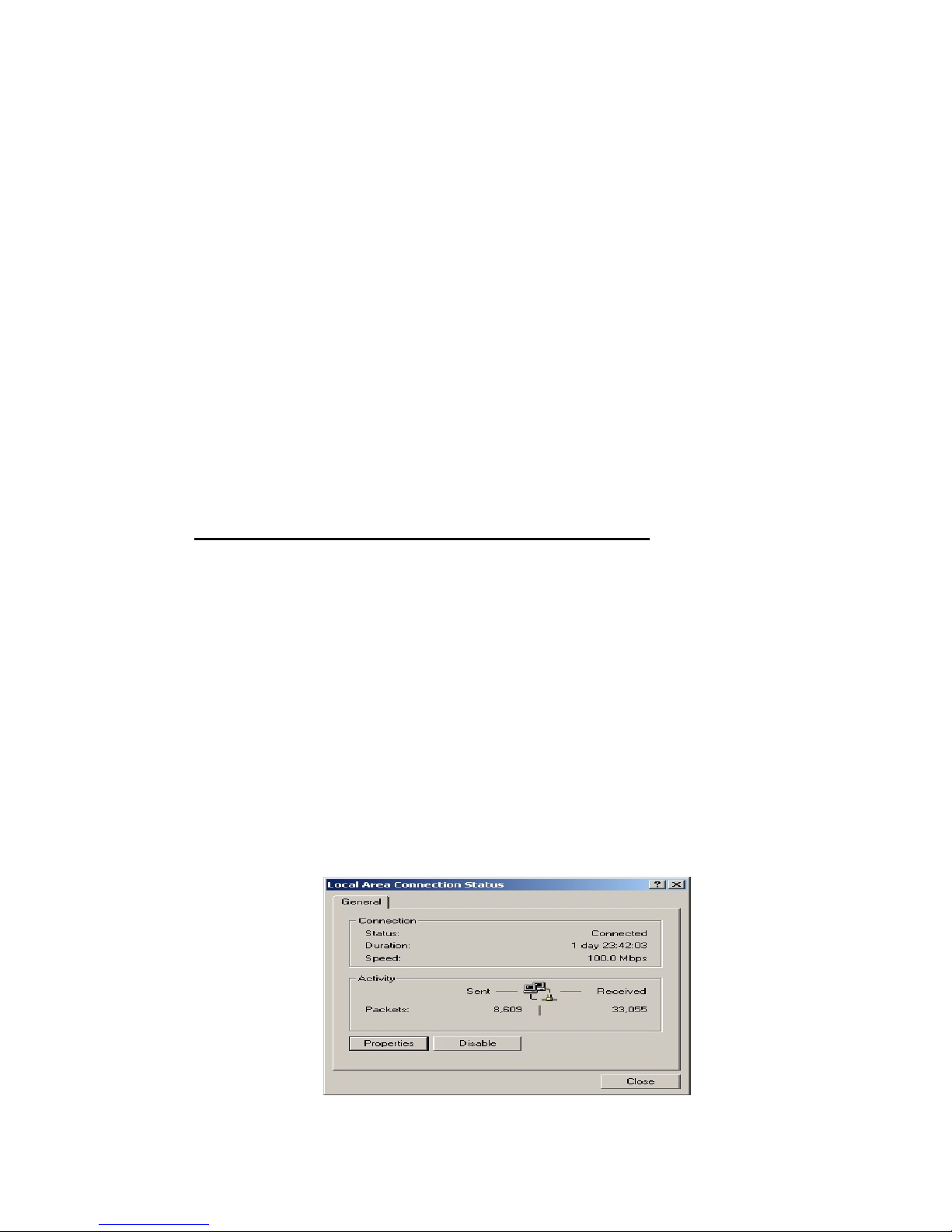
The Local Area Connection Status dialog box appears, seen
in FIGURE 3-1:
Page 9
9
FIGURE 3-1: Local Area Connect ion Status dialog box
3.2.3. Click Properties.
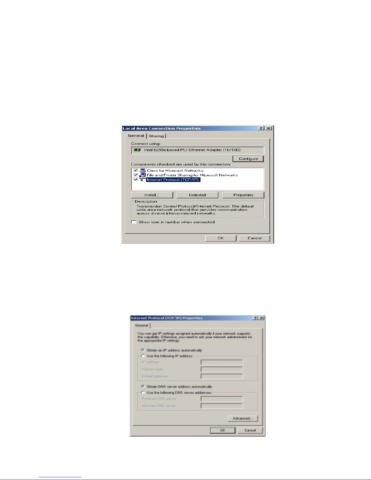
The Local Area Connect ion Propertie s dia log box appears,
seen in FIGURE 3-2:
FIGURE 3-2: Local Area Connection Properties dialog box.
3.2.4. Click Internet Protocol (TCP/IP), then click Properties.
The Internet protocol (TCP/IP) Properties dialog box appears,
seen in FIGURE 3-3:
Page 10

10
FIGURE 3-3: Internet Protocol (TC P/IP) Properties dialog box
3.2.5. Click Obtain an IP address automatically and Obtain DNS
server address automatically.
3.2.6. Click OK.
You need restart your computer now or at a later time.
3.3 Collecting ISP Information
Yo u need query the relev ant information from your ISP before
configuring your router, for example:
Has your ISP assigned you a s tatic or dy namic IP address? If you
have obtained one static IP address, what is it?
Does your ISP use PPPoE? If so, what is your PPPoE user name
and password?
If you are not sure of the above questions, call your ISP to clarify them.
Note :
The procedural steps above apply to Windows 2000 only. For Windows
95/98/ME/NT/XP, refer to your Windows Documentation.
Page 11
11
4. Basic Functi o ns
In this chapt er , you will le a rn how to use basi c functions tha t the
Company AP Router provides, including Setup, Global Address,
Wireless Tools, Status, DHCP, Log and Printer.
The X-Micro WLAN 11g Broadband Router provides you a
Web-based Administration Tool with which you can easily set
up the router and customize the basic rout er settings. You can
use this Web-based Tool from any computer in your network.
4.1 To Open the Web-based Administration Tool:
4.1.1. Open the browser on your PC.
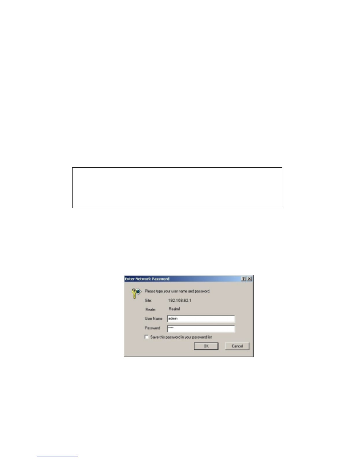
4.1.2. Type http://192.168.62.1 in the Address bar.
The Logon dialog box appears, seen in FIGURE 4-1:
FIGURE 4-1: Logon dialog box
Notes :
Micr os of t In te rn et Exp l or er 5.0 or late r is hi ghl y r e com men d ed for using
this Web-based Tool.
Graphics sampled in this chapter are provided for illustrations only. They
may sligh t ly differ from your own r outer scr een s.
Page 12
12
4.1.3. Type admin in the User Name box.
4.1.4. Type the password in the box.
4.1.5. Optional. To log on to the Administration Tool once for all,
select the check box of Save this password in your password
list.
4.1.6. Click OK.
The Company AP Router Administration Tool appears.
Note :
The default password is “1234”. You can change the password on
th e Tools page. Fo r det ailed instructi on s, see To Change the
Administrative Password for Your Router.
Note :
The Administration Tool will time out after a per iod of idling, the Router
may ask you to log on again.
Page 13
13
4.2 Setup
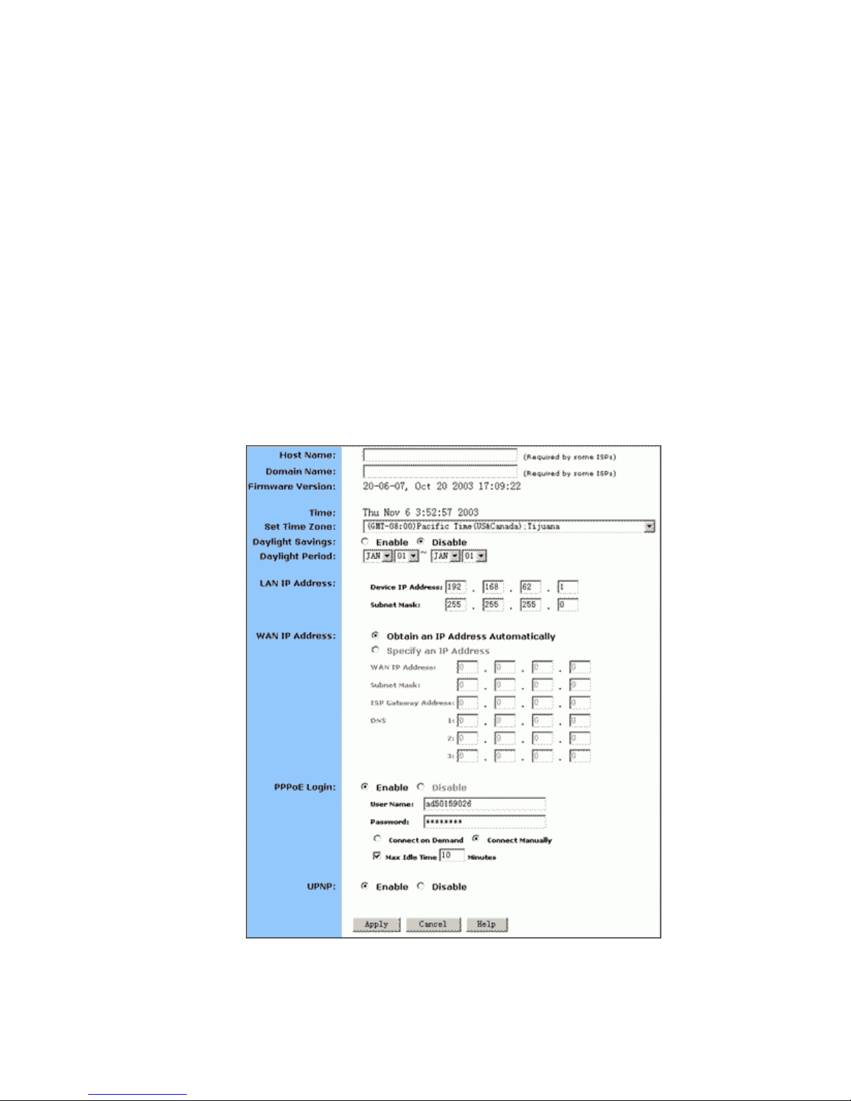
The Setup page allows you to edit the basic configuration
parameters for your router, such as Host Name, Domain Name, LAN
IP Address, WAN IP Address, PPPoE Login, UPNP, and so on.
In most cases, the default setti ngs will be Okay for you. However,
different ISPs ( Internet Service Prov ider) may ask f or spec ific
requireme nts, please check it with your ISP if you are not sure.
4.2.1. T o Confi gure Setup Parameters:
4.2.1.1. Click Setup on t he navi ga t i on ba r.
The Setup page appears, seen in FIGURE 4-2:
FIGURE 4-2: Setup page
Page 14
14
4.2.1.2. Type the Host Name, System Name or Account Name in
the Host Name box if your ISP requires.
4.2.1.3. Type the Domain Name of your ISP in the box if your ISP
requires, such as xyz.isp.com.
4.2.1.4. Optional. Review the firmware version number and date
information that you are currently using.
4.2.1.5. Select a specific Time Zone from the Set Time Zone
drop-down list, such as (GMT+08:00) Beijing, Chongqing, H ong
Kong, Urumqi.
4.2.1.6. If you want to use Daylight Savings time, click Enable
and select the start date and end date from the Daylight Period
drop-down lists .
4.2.1.7. If you don’t want to use Daylight Savings time, click
Disable. If you select to disable the Daylight Savings, Daylight
Period will not take effect any more.
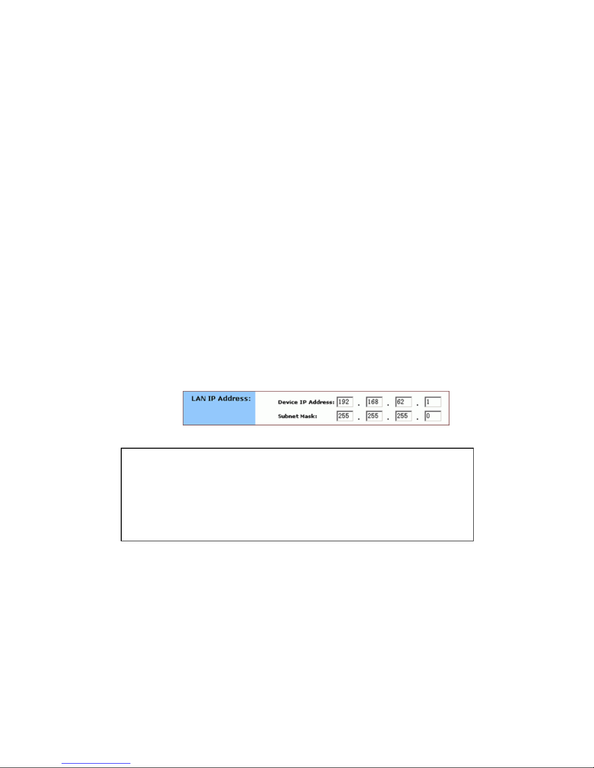
4.2.1.8. Optional. Review the Device IP Address and Subnet
Mask next to LAN IP Address and change the information if
necessary.
4.2.1.9. If you have enabled the DMZ feature on the DHCP page,
review the DMZ IP Address and Subnet Address next to DMZ IP
Address and change the information if necessary.
4.2.1.10. For WAN IP Address (Wide Area Network, also called
Public IP), choose either Obtain an IP Address automatically or
Specify an IP Address if your ISP has assigned you with static
IP).
Notes :
Device IP Address and Subnet Mask are invisible to users on the LAN
(Local Area Network) only.
In most cases , you need not make any change to LAN IP Address. If you
change t he LAN IP Address with DHCP enabled, you need to restart
your client PCs; otherwise, you need reconfigure your client’s IP
addresses manually.
Page 15
15
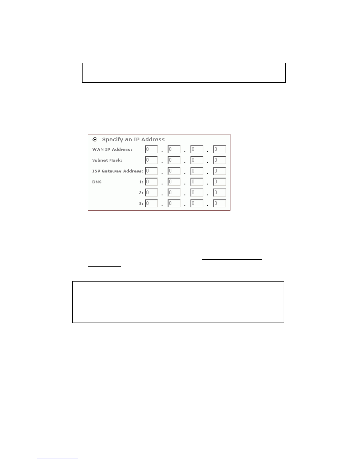
4.2.1.11. Optional. If you select Specify an IP Address, type the
WAN IP Address, Subnet Mask, ISP Gateway Address and DNS
in the boxes, seen in FIGURE 4-3. You can collect such
information from your IS P .
FIGURE 4-3: WAN IP Address - Specify an IP Address
4.2.1.12. If your ISP uses PPPoE (Point to Point Protocol over
Ethernet), click Enable next to PPPoE Login; otherwise, click
Disable. For detailed instructions on how to set the PPPoE
Login parameters in FI GU R E 3- 4, see To Set PPPoE Login
Parameters below.
4.2.113. If you want to use UPNP (Universal Plug and Play) to
plug devices lik e PC s , rout ers and others into a network a nd to
automatically know about each other, click Enable next to UPNP;
otherwise, click Disable.
4.2.1.14. When you have completed all the settings, click Apply,
or click Cancel to undo y our ch ange s .
Note :
If
y
ou choose to obtain an IP Address automatically, skip Step 11.
Notes :
Usin g PPPoE, your ISP can authenticate your connection with a specific
user name and password for security issues.
If you enable PPPoE, make sure to uninstall all existing applications on
any compu t er in your n et wor k
.
Page 16
16
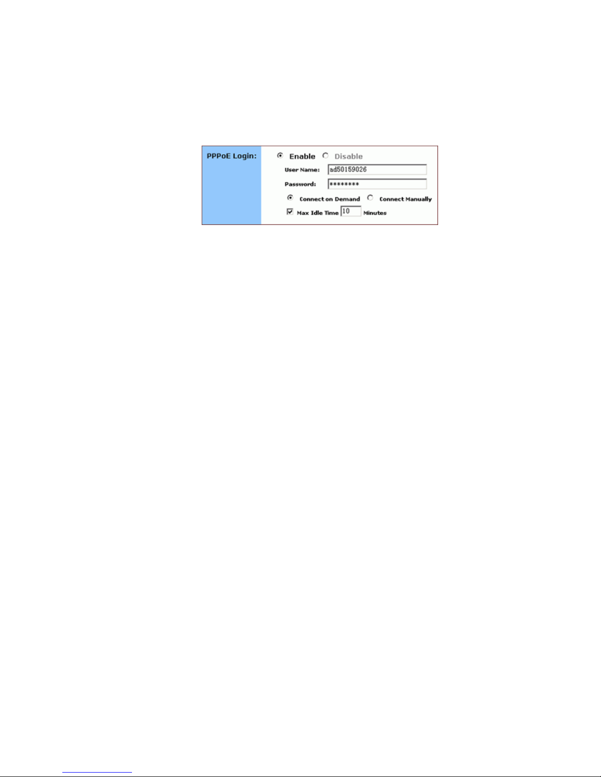
4.2.2. To Set PPPoE Login Parameters:
4.2.2.1. Click Enable next to PPPoE Login.
FIGURE 4-4: Set PPPoE Login Parameters
4.2.2.2. Type the User Name and Password provided by your
ISP.
4.2.2.3. For connection types, you can select either Connect on
Demand or Connect Manually.
4.2.2.4. Optional. If you want to limit the idling minutes, select
Max Idle Time and type a maximum number in minutes.
Page 17
17
4.3 Global Address
On the Global Address page, you can set up NAT (Network Address
Translation) to provide internal-to-external IP address mappings.
Have you enabled DMZ on the DHCP page? Depending on whether DMZ
is enabled, you may follow different procedural steps.
What do you want to do?
Set up Global Address with DMZ Disabled
Set up Global Address with DMZ Enabled
Remove Global Addresses
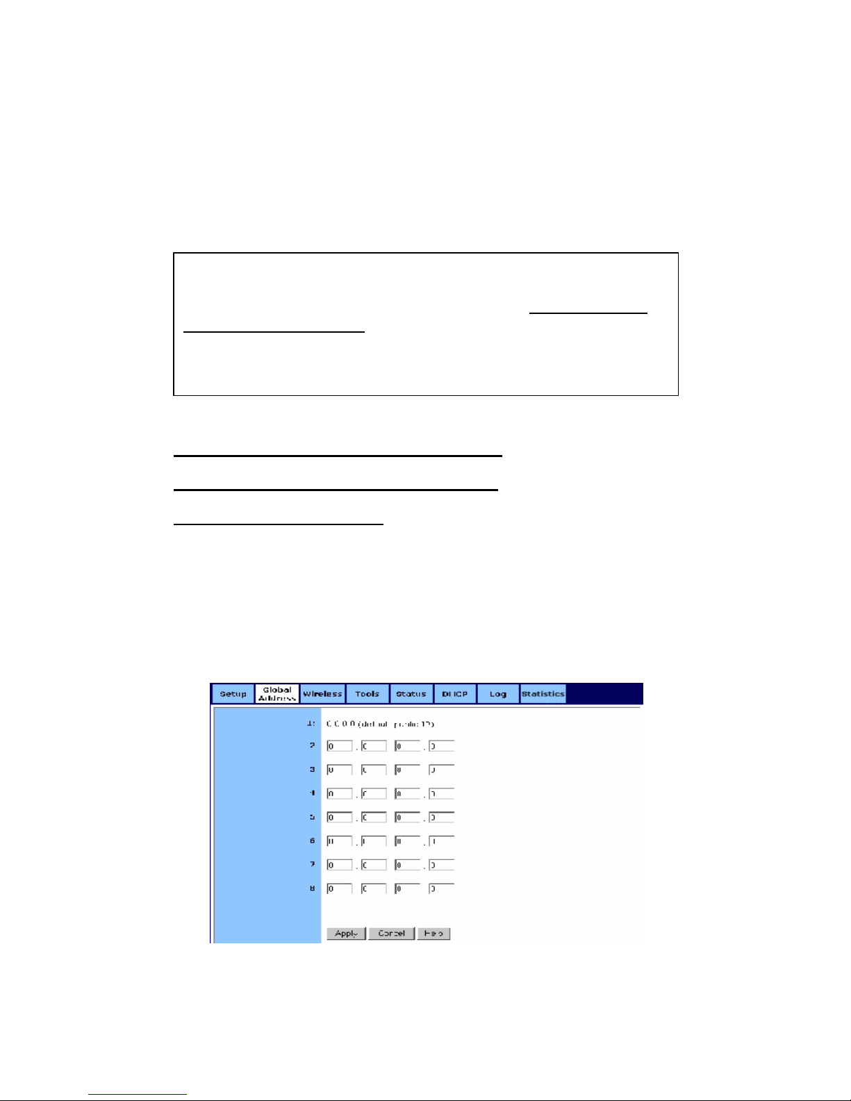
4.3.1. To Set up Glob a l Ad dre ss wit h DMZ Disa b led :
4.3.1.1. Click Global Address on the navigation bar.
The Global Address page with DMZ Disabled appears, seen in
FIGURE 4-5:
FIGURE 4-5: Global Address Page with DMZ Disabled
Notes :
If you want to use Global Address mapping, you must enable NAT
on the Filte r s page. For detailed i nstruction s, see To Set up a Port
Filtering or Raw IP Filter.
If you have chosen to retriev e an IP address automatically, you will
not need to use this function. Instead, the default public IP address
will display on the Global Addre ss page.
Page 18
18
4.3.1.2. Review the first line in the above figure. It shows the
default WAN I P addr e ss whi c h is s peci f ie d on t he Set u p pag e. If
your ISP assigns you an IP address automatically, it will display
here.
4.3.1.3. In Line 2 – Line 8, you can list up to 7 additional static,
external IP addresses provided by your ISP.
4.3.1.4. When you have completed editing all the settings, click
Apply, or click Cancel to undo your changes.
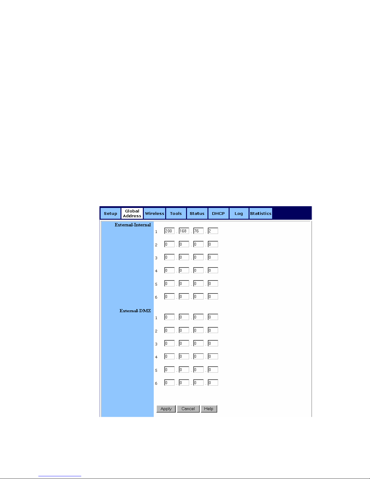
4.3.2. To Set up G loba l Ad dre ss wit h DMZ Ena b led :
4.3.2.1. Click Global Address on the navigation bar.
The Global Address page with DMZ E nabled appears, seen in
FIGURE 4-6:
FIGURE 4-6: Global Address Page with DMZ Enabled
Page 19

19
4.3.2.2. Review the first line in the above figure. It shows the
default WAN I P addr e ss whi c h is s peci f ie d on t he Set u p pag e. If
your ISP assigns you an IP address automatically, it will display
here.
4.3.2.3. Next to External - Internal, you can list up to 6 static,
external IP addresses provided by your ISP.
4.3.2.4. Next to External – DMZ, define for your DMZ network up
to 6 static, external global IP addresses provided by your ISP.
4.3.2.5. When you have completed editing all the settings, click
Apply, or click Cancel to undo your changes.
4.3.3. To Remove Global Addres ses:
4.3.3.1. Click Global Address on the navigation bar.
4.3.3.2. For any entry you want to delete, enter 0.0.0.0, and click
Apply.
Page 20

20
4.4. Wireless
Using Wireless, you can conf igure your router for w ir eless access.
There are three parts on the Wireless page:
Radio Settings : Allows you to configure your Gateway for wireless
access, including Wireless Enable/Disable, Mode, ESSID, Beacon
Interval, RTS Threshold, Preamble Type, Distribution System, and
so on.
Sec urit y Setti ng: Allows you t o conf igure your G atewa y for s ecurit y
issues.
Status: Allows you to find out your Gateway’s AP Radio statistics
and wireless devices of which the AP (Ac cess Point) is aware.
You can easily toggle between the above three parts on the Wireless
page.
On the Radio Setting s page, Wire les s Distribution Sys tem as defined
by the IEEE 802.11 standard has been made available on the
Company AP Router now. Hence, it is possible to wireles sly connect
Access Points using up to 8 MAC Addresses of PC cards, so that
you can extend a wired infrastr ucture to loc ations w here cabling is
not available. T hus those users can roam or st ay connected to the
availab le network resourc es.
What do you want to do?
Set the Wireless R adio Parameters
Set the Wireless Security Parameters
Review Wireless Status
Disable Wireless
4.4.1. T o Set the Wir eless Radi o Parameters:
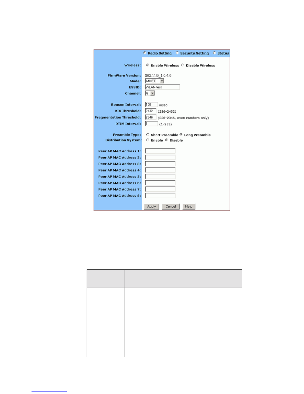
4.4.1.1. On the Wireless page, select Radio Settings.
The Radio Settings page appears, seen i n FI GU R E 4-7:
Page 21
21
FIGURE 4-7: Wireless – Radio Settings Page
4.4.1.2. Click Enable next to Wireless.
4.4.1.3. Optional. Review the firmware version number and date
information that you are currently using.
4.4.1.4. Enter the following basic radio parameters:
Paramet
er
Description
Mode
Selects the Wirel ess Mode that your
Company AP Router supports from the
drop-down list.
Avail able options ar e 802.11B, 802.11G, and
MIXED which supports both 8 02.11B and
802.11G.
ESSID
Type the uniq u e identi fier fo r th e Exten de d
Service Set which is shared by client stations
in an infr astructure association, such as
WLAN-test.
Page 22

22
It is case-sensitive and cannot exceed 32
characters.
Channel
Selects o ne IEEE 802.11G channel for
wireless LAN tran smissio n s from the
drop-down list.
Specifi es the bandwidth whi ch the wireless
radio operates. AP and the cli ent stations t h at
is associated work in one of channels from 1
to 14.
4.4.1.5. Enter the following advanced radio parameters:
Parameter Description
Beacon
Interval
Type the time interval in milliseconds
between beacons broadcast by AP
(Access Point) in the Beacon Interval box,
such as 100.
RTS
Threshold
Type a number in the RTS Threshold box.
Also called Request-to-Send Threshold.
This field specifi es the minimum size of
data frames above whi ch R TS protocol
is used, ranging from 256 to 2432. RTS
helps prevent data collision from hidden
nodes.
Fragmentatio
n Threshold
Type a number in the Fragmentation
Threshold box.
For efficiency in high-traffi c situatio ns,
large files are split i nto fragm ent s. Thi s
field specifies t he d efault packet size, an
even number ranging fr om 256 to 2346.
DTIM Interval
Type a number in the D TIM Inte rval box.
Also called Deli very Tr affic I ndic ati on
Map . Th i s field sp e ci fies the numb er of
beacon intervals between successive
DTIMs, rangin g from 1 to 255.
Preamble
Type
Select either Short Preamble (72 bits) or
Long Preamble (144 bits).
Distribution
System
If you want to use Wireless Distr ibut io n
System on your Rout er , click Enable
next to Distribut ion System, then type the
dist r i b uted clie nt P C s’ physical
addresses, as described in Step 6.
Otherwi se, cli ck Disable.
Page 23
23
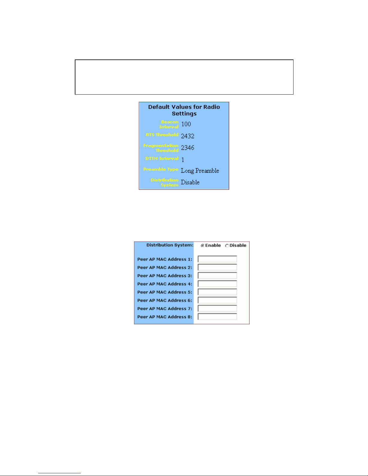
FIGURE 4-8: Default Values for Radio Settings
4.4.1.6. Optional. If you have enabled Distribution System, type
the physical addresses of distributed client PCs in a wireless
network in the Peer AP MAC Address 1-8 boxes, seen in
FIGURE 4-9:
FIGURE 4-9: Peer AP MAC Addresses for Distribution
Systems
4.4.1.7. When you have completed editing all the settings, click
Apply, or click Cancel to undo your changes.
4.4.2. To Set Wireless Security Param eters:
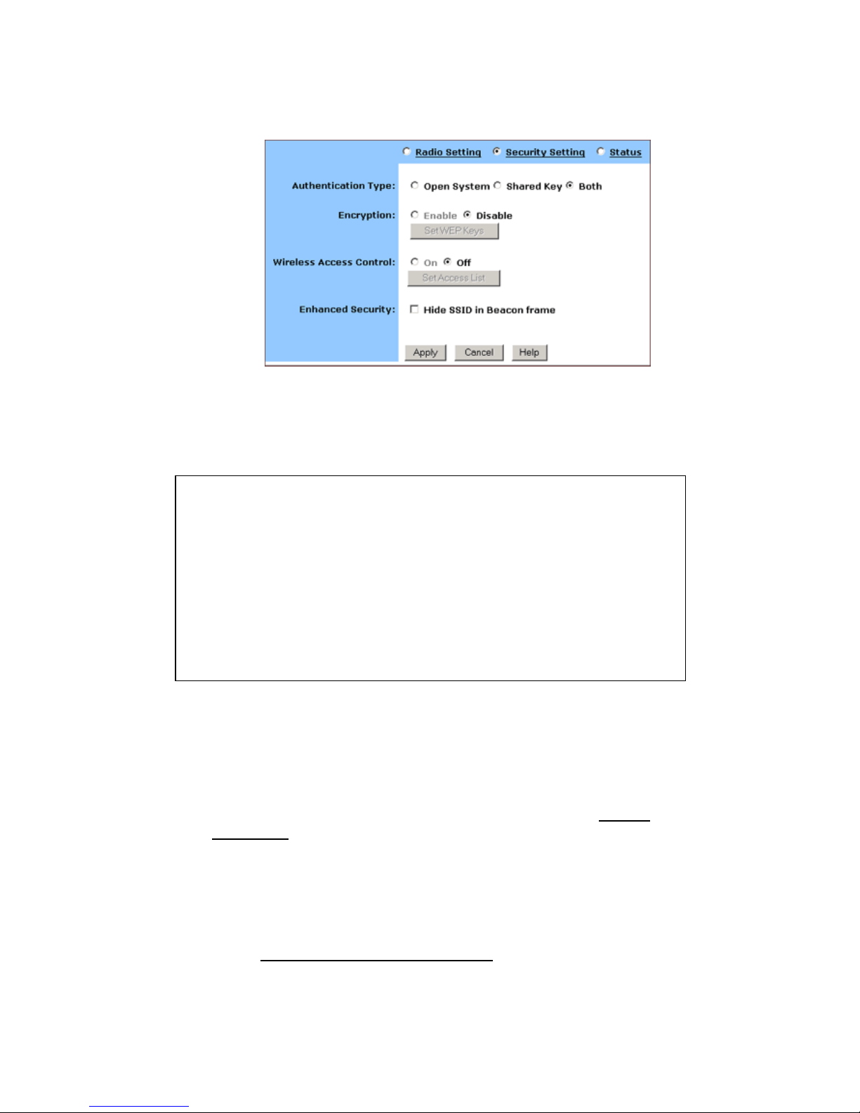
4.4.2.1. Click Security Settings on the Wireless page.
The Security Settings appears, seen in FIGURE 4-10:
Note :
You can see th e default values of the above advanced wireless settings on
the right of the page. If you don’t know how to change the settings, please
leave as they are in Fi gure 4-8:
Page 24
24
FIGURE 4-10: Wireless – Security Settings Page
4.4.2.2. Select one of Open System, Shared Key and Both from
the Authentic ation Type drop-down list.
If you want to prevent other stations without specific WEP
(Wired Equivalent Privacy) keys from linking to the AP, select
Enable next to Encryption and then click Set WEP Keys to
specify relevant keys; otherwise, select Disable. For detailed
instructions on how to set the WEP Keys, see below To Set
WEP Keys.
If you want to allow access to the Internet based on user’s MAC
(Media Access Control) address, select On next to Wireless
Access Control and then click Set Access List to specify
relevant MAC addresses; otherwise, click Off. For detailed
instructions on how to specify relevant MAC addresses, see
below To Set Wireless Ac ce ss Control
.
Notes :
Authentication Type indicates an authentication algorithm which can be
supported by the Access Point:
Open System: The simplest of available au thent ication algorithms.
Essentially it is a null algorithm. Any station that requests auth e ntication
with this algorithm may become authenticated if Open System is set at the
recipient station.
Shared Key: Allows stations with a specific WEP (Wired Equivalent
Privacy) Keys to be authenticated.
Both: Supports the authentications of either stations who know a shar e d
key or those wh o do not.
Page 25
25
4.4.2.3. Next to Enhanced Security, select either Enable or
Disable. If you choose to enable the enhanced security feature,
go to Step 6.
4.4.2.4. Optional. If you have enabled Enhanced Security, you
can choose to hide your SSID (Service Set Identifier) in Beacon
frame.
4.4.2.5. When you have completed editing all the settings, click
Apply, or click Cancel to undo your changes.
4.4.3. T o Set WEP Keys:
4.4.3.1. On the Security Settings page, enable the Encryption
and click Set WEP Keys.
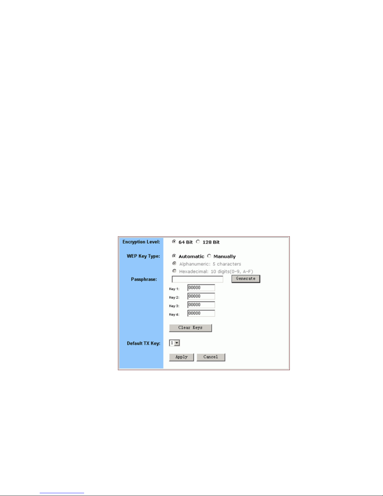
The Set WEP Keys window appears, seen in FIGURE 4-11:
FIGURE 4-11: Set WEP Keys Window
4.4.3.2. Select either 64 Bit or 128 Bit next to Encryption Level.
Page 26

26
4.4.3.3. If you want to generate WEP Keys automatically, do the
following action:
4.4.3.3.1. Select Automatic next to WEP Key Type.
4.4.3.3.2. Type a string of any words in the Passphrase
box, and click Generate.
Four newly generated WEP Keys will display
in the Key 1 – Key 4.
4.4.3.3..3. Opt ional. Click Clear Keys to reset all the keys
to null.
4.4.3.4. If you want to enter the key elements manually, do the
following a c t ion:
4.4.3.4.1. Select Manually next to WEP Key Type.
4.4.3.4.2. I f you select Alphanumeric: 5 characters, type
a string of 5 alphanumeric characters in the Key
1 – Key 4 boxes respectively.
4.4.3.4.3. If you select Hexadecimal: 10 digits (0-9, A-F),
type a string of 10 hexadecimal digits in the Key
1 – Key 4 boxes respectively.
4.4.3.4.4. Opt ional. Click Clear Keys to reset all the keys
to null.
Note :
128 Bit e ncryption c an provide you a more secure encryption algorithm,
but it will slow down your network dat a transmission rates.
Note :
Make sure that you write down the passphrase string, so that you can
refer to it if necessary.
Page 27
27
4.4.3.5. Select the default encryption key from the Default TX
Key drop-down list, such as Key 1.
4.4.3.6. When you have completed editing all the settings, click
Apply, or click Cancel to undo your changes.
4.4.4. T o Set Wireless Access Co ntrol:
4.4.4.1. On the Security Settings page, set the Wireless Access
Control On and click Set Access List.
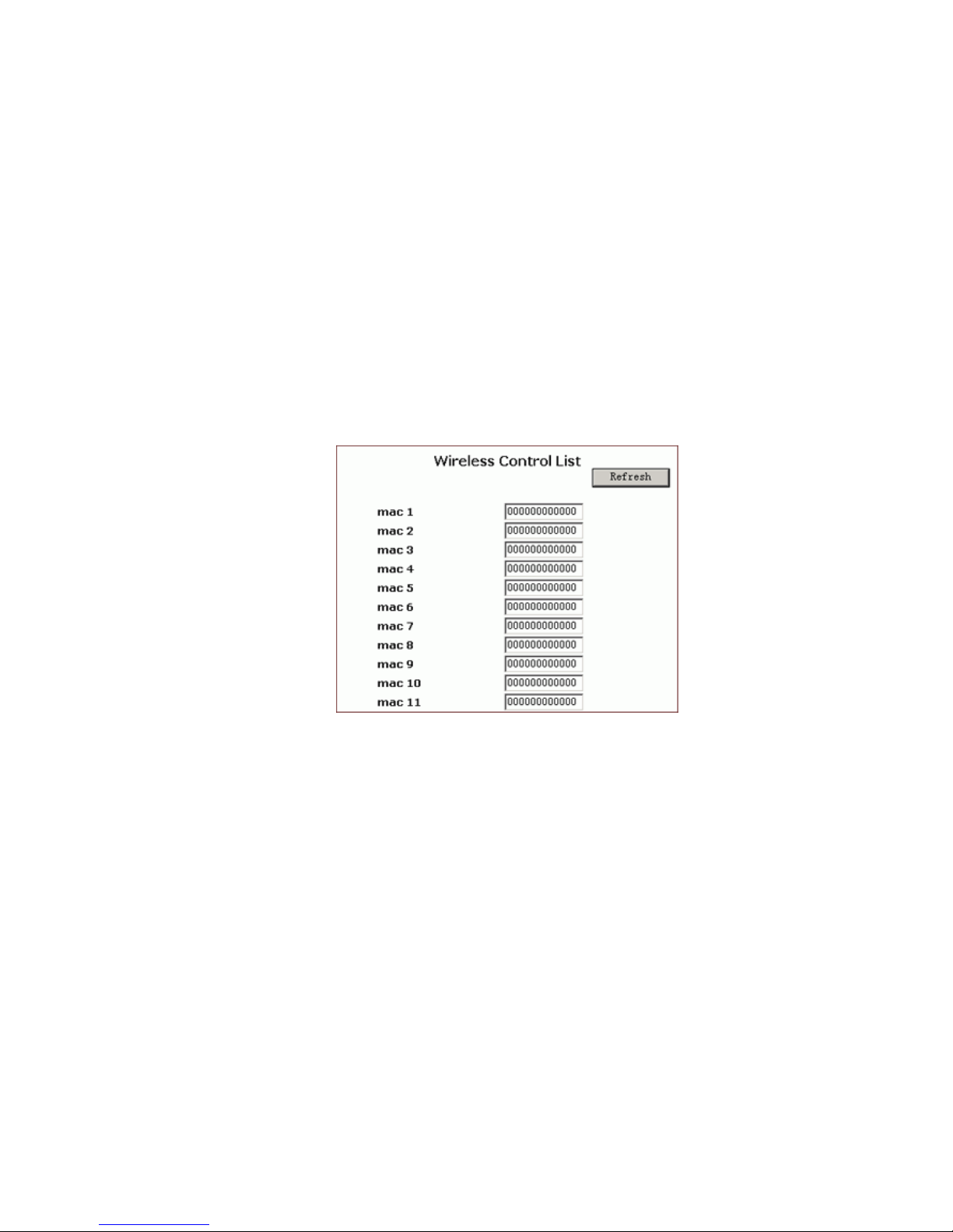
The Window Control List window appears, s een i n FIGUR E
4-12:
FIGURE 4-12: Wireless Control List window
4.4.4.2. Type the MAC addresses that you want to allow to access
the Internet. You can specify up to 80 MAC addresses in the
list.
4.4.4.3. When you have complete editing all the MAC addresses,
click Submit, or click Cancel to undo your changes.
4.4.4.4. Optional. You can click Refresh to see the most current MAC
addresses in effect.
4.4.5. To Review Wir eless Status:
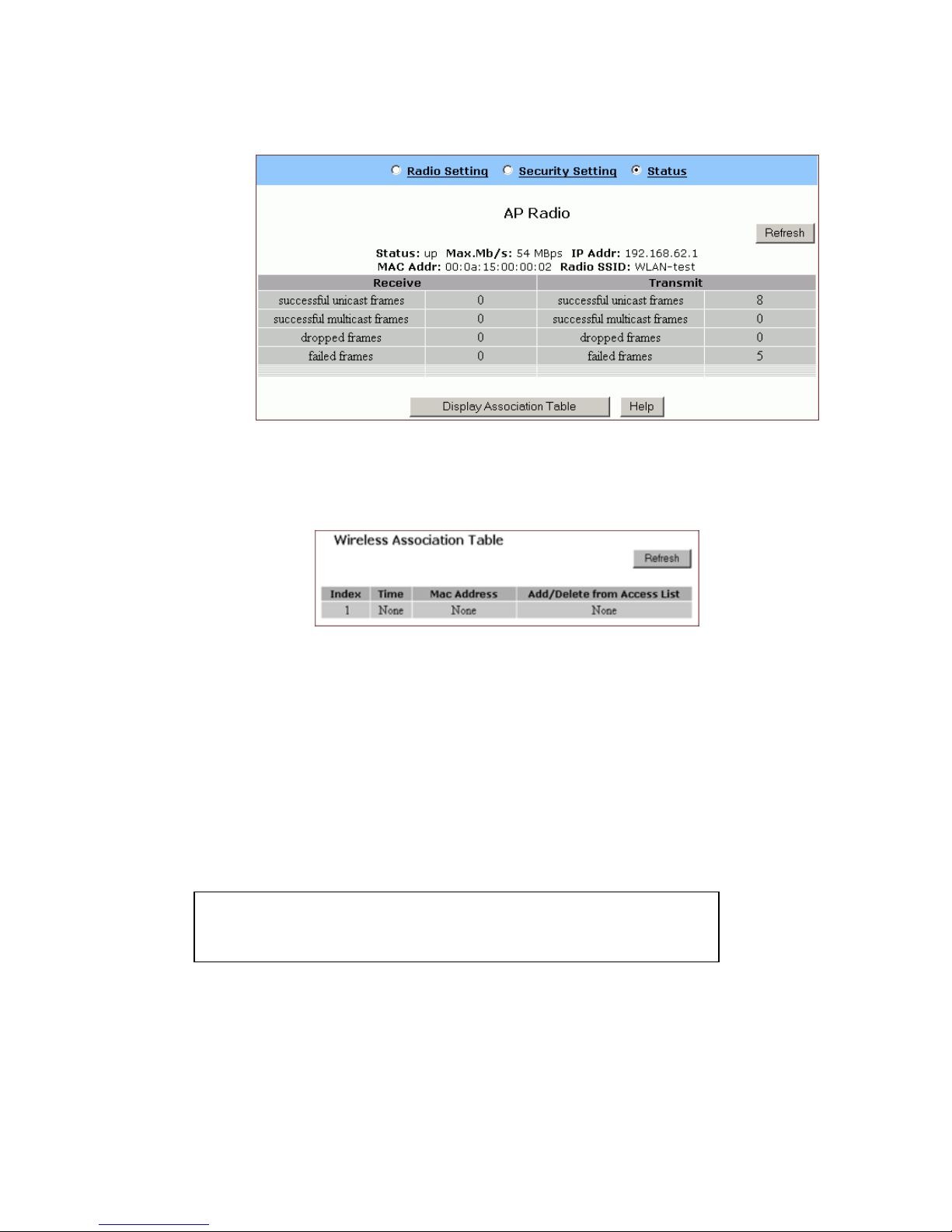
4.4.5.1. On the Wireless page, select Status.
The Status page appears with your GateWay’s AP Radio
statistics including Status, Max.Mb/s, IP Addr, MAC Addr, Radio
SSID, Receive data and Transmit dat a. Seen in FIGURE 4-13:
Page 28
28
FIGURE 4-13: Wireless – Status Page
4.4.5.2. To see the wireless devices of which the AP (Access
Point) is aware, click Display Association Table.
4.4.5.3. Optional. You can click Refresh to see the most current
data.
4.4.6. To Disable Wireless:
4.4.6.1. On the Wireless page, select Radio Settings.
The Radio Settings page appears, seen i n FIGURE 4-7.
If you don’t want the router to support Wireless, select Disable.
Note :
None of the router’s wireless functions will work unless you enable it.
Page 29
29
4.5 Tools
On the Tools page, you can:
Change the Administrative Password for Your Router
Restore the Fac to ry Default Conf ig urat ion
Reset Gateway
Upgrade the Firmware
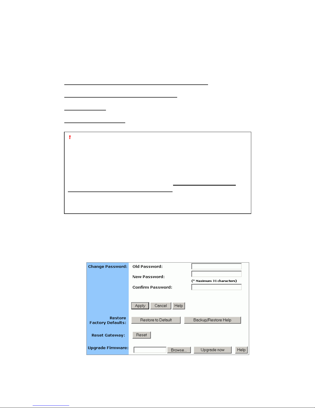
4.5.1. To Change the Administrative Password for Your Router:
4.5.1.1. Click Tools on the navigation bar.
The Tools page appears, seen in FIGURE 4-14:
FIGURE 4-14: Tools Page
Important:
We strongly recommend that you change the administrative password
after the first login.
Restoring the default factory settings will reset all of the router
configurations in every page, so we recommend that you backup the
confi gu r ation dat a from the Gateway to your PC simply using DO S
commands. In addition, you can also restore the factory defaults under the
DOS window. For detailed ins tructions, see To Backup or Restore the
Configuration Data Using DOS Commands.
If you want to reset the hard ware, you need reset the Gateway.
Before upgradin g the firmware, you need download the firmware image
file from the Gateway Web site and save it to your root local drive first.
Page 30
30
4.5.1.2. Type the Old Pas swo rd in the box. The default pas s word
is 1234.
4.5.1.3. Type a New
Password in the box.
4.5.1.4. Type the new password in the Confirm Password box.
4.5.2. T o Restore the Factory Default Config ur ation:
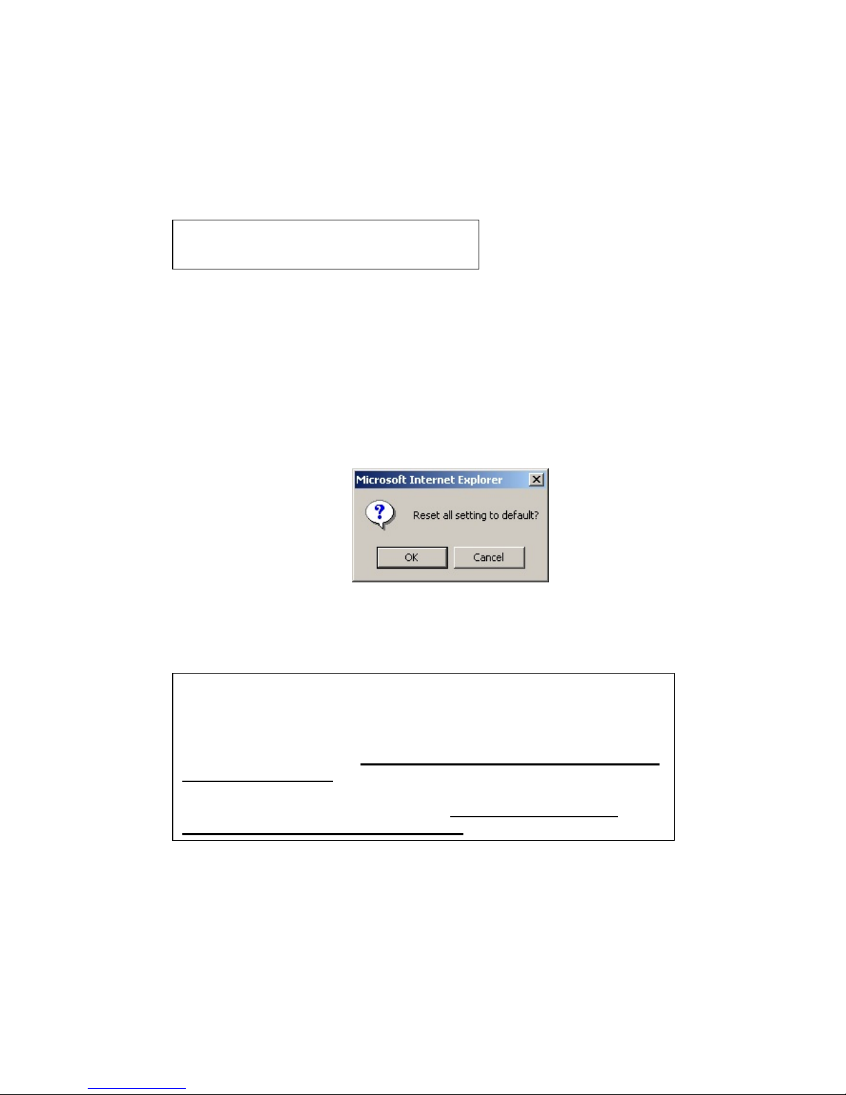
4.5.2.1. On the Tools page, click Restore to Default next to
Restore Factory Defaults.
The Warning dialog box appears, see FIGURE 4-15:
FIGURE 4-15: Warning Dialog Box
4.5.2.2. Click OK.
4.5.3. T o Backup or Restore th e Config uration Data Using
DOS Commands :
For th e backup of the configurati on data f rom the Gateway to your
PC, Gateway acts as a TFTP server.
Note :
Password must be less than 64 characters.
Important:
Restoring the default factory settings will reset all of the router
configurations in every page, so we recommend that you backup the
configuration data from the Gateway to your PC first using DOS
commands. For details, see To Backup or Restore the Configuration D ata
Using DOS Commands.
In addition, you c an also restore the factory defaults using DOS
commands. For detailed in struction s, see To Backup or Restore the
Configuration Data Using DOS Commands.
Page 31

31
To back up the co nf iguration data, under t he DOS window, use the
following command:
tftp –i gateway_Ip_address GET filename
To restore the configuration da ta, under the DOS windo w, use the
following command:
tftp –i gateway_Ip_address PUT filename
gateway_Ip_address: The IP address of the Gateway where you
want to back the configuratio n dat a.
filename: The file name for bac kup from the Gate wa y. It must begin
with “nvram” which is not case-sensitive, such as
“nvram__11032003”.
4.5.4. T o Reset Gateway:
If you want to reset the hardware, click Reset next to Reset
Gateway on the Tools page.
4.5.5. T o Upgra de the Firmware:
4.5.5.1. Download a firmware image file from the Gateway Web
site and save it to your ro ot loc al drive.
4.5.5.2. Type the file path and file name in the Upgrade Firmware
box, or click Browse to launch a Choose file dialog box, seen in
Page 32

32
FIGURE 4-15:
FIGURE 4-15: Choose File Dialog Box for Upgrading
Firmware
4.5.5.3. Locate the firmware you have downloaded and click
Open.
4.5.5.4. The Choose file dialog box closes.
4.5.5.5. Click Upgrade Now. The firmware of the device will be
upgraded.
Caution :
The firmware upgrade m ay take about 10 secon ds, please DONOT
power off the unit when it is being upgraded.
Page 33
33
4.6 Status
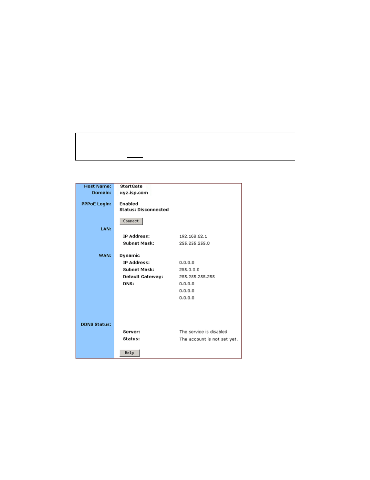
On the Status page, you can view the m ost current information about
your Router whic h w i ll be continuously refres hed per 10 seconds,
such as Host Name, Domain, PPPoE Logi n, LAN/WAN and DDNS
Status. Different config urat io n may bring you to d ifferent data,
compared in FIGURE 3-16 and FIGURE 4 - 17.
If you have enabled the PPPoE Login, the Stat us page will display
as illustrated in FIGURE 4-16:
FIGURE 4-16: Status Page with PPPoE Login Enabled
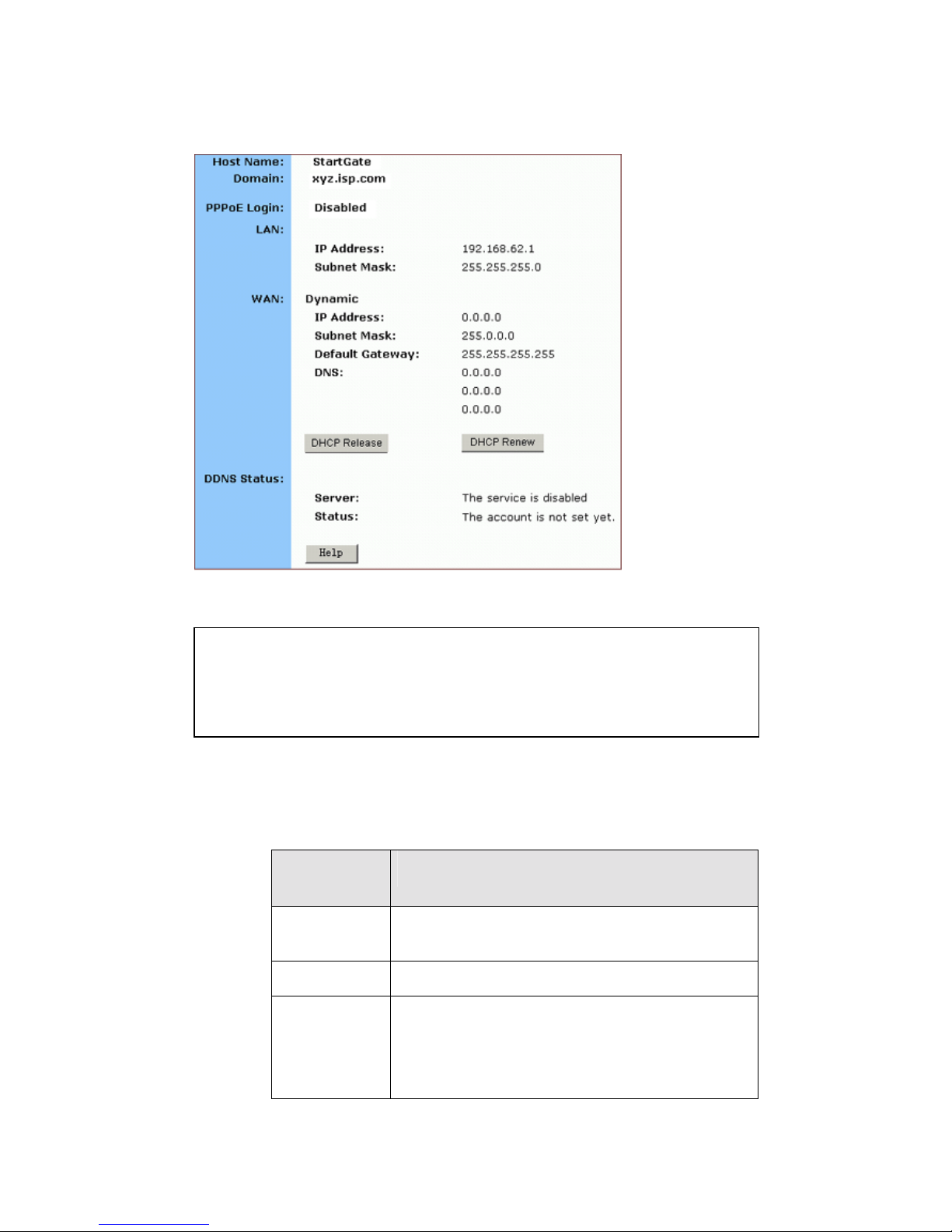
If you have c hosen the Dynamic IP a nd disabled PPPoE Login, t he
Status page will dis play as illustrated in FIGURE 4-17:
Note :
If you want to change the configur ation, go to the Setup page. For det ailed
instru ctions, see Setup
.
Page 34
34
FIGURE 4-17: Status Page with PPPoE Login Disabled
Status Detail:
Paramet
er
Description
Host
Name
Shows th e name of the d evice.
Domain
Shows the domain name of the device.
PPPoE
Login
Shows the current statu s of PPP oE Logi n:
Disabled
Enabled: Connected, Connecting or
Notes :
If you have chosen the Dynamic IP and disabled PPPoE Login, you can see
the DHCP Release and DHCP Renew buttons:
To release the most current WAN IP address, click DHCP Release.
To renew the WAP IP address, click DHCP Renew.
Page 35

35
Disconnected.
LAN
Shows the current IP Ad dress and Subnet
Mask of the device, as seen by users in your
internal network.
WAN
Shows the IP Address, Subnet M ask, Default
Gateway, and DNS of the router, as seen by
external users on the Internet.
DDNS
Shows the Dynamic DNS Server and Status.
If you want t o change the setting, go to the
Advanced Dynamic DNS page. For details
instructions, see To Configure a Dynamic
DNS Server.
Page 36
36
4.7 DHCP
On the DHCP page, you can set your NAT/Firewall Gateway as a
DHCP (Dynamic Host Configuration Protocol) server, and DHCP
servers will automatically assign IP addresses to all the client PCs in
your network.
What do you want to do then?
Set Your Router as a DHCP Server
View the Active IP Table
Disable DHCP on Your Router
4.7.1. T o Set Your Router as a DHCP Server:
4.7.1.1. Make sure that there is not already a DHCP server on
your router.
4.7.1.2. Make sure that each PC in your network is configured to
receive an IP address automatically.
4.7.1.3. Click DHCP on the navigation bar.
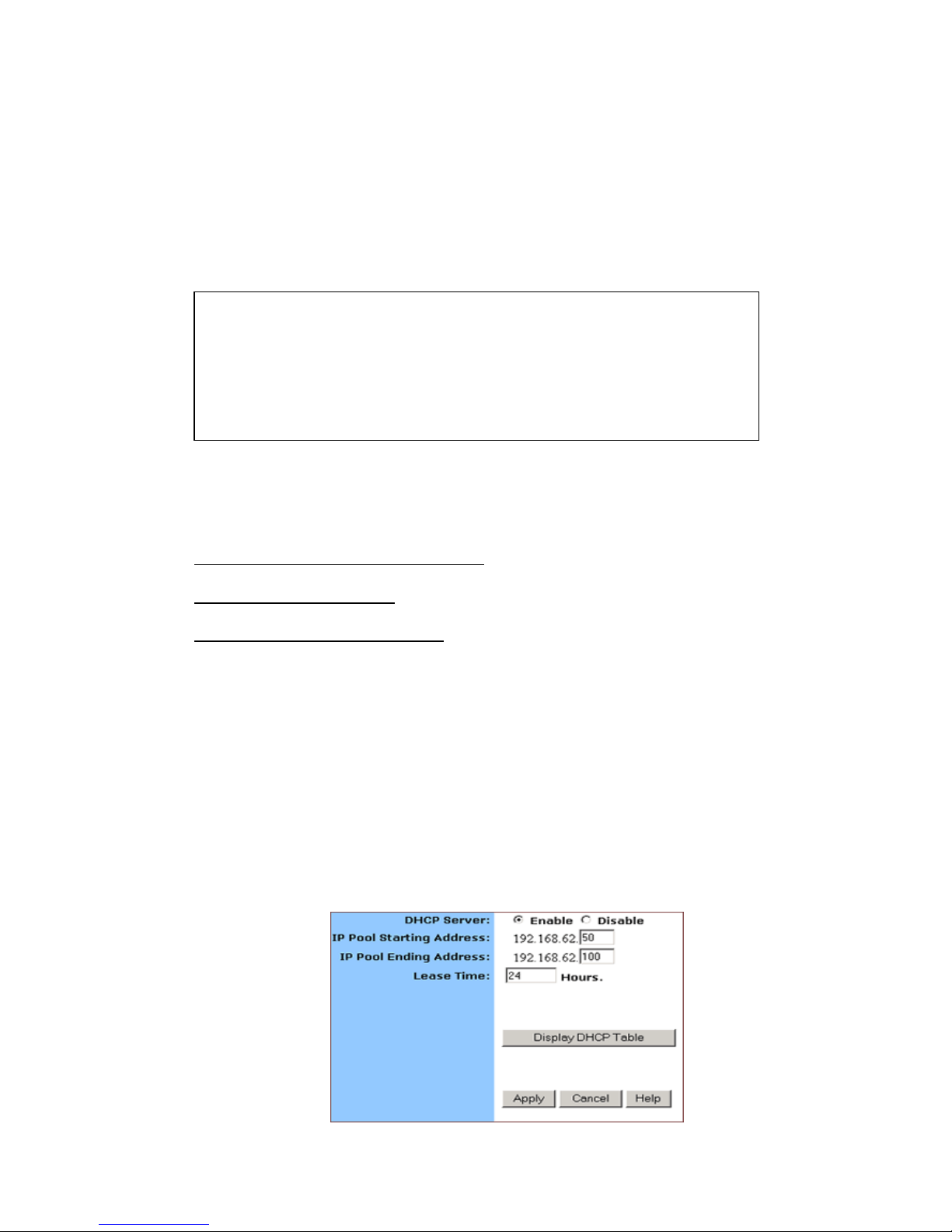
The DHCP page appears, seen in F IGURE 4-18:
Notes
If you w ant to enable DHCP, make sure that there is not already a DHCP
server on your router.
If you don’t enable DHCP on your router , you will need to manually
configure an IP address for each PC in your network; if you do enable
DHCP, make sure that each PC is configu red to receive an IP address
automatically.
Page 37
37
FIGURE 4-18: DHCP Page
4.7.1.4. Click Enable next to DHCP Server.
4.7.1.5. Type a IP Pool Starting Address to designate the first IP
address that can be assigned to a PC in your network.
4.7.1.6. Type a IP Pool Ending Address to designate the last IP
address that can be assigned to a PC in your network.
4.7.1.7. When you have completed editing all the settings, click
Apply, or click Cancel to undo your changes.
4.7.2. To Disable DHCP on Your Router:
4.7.2.1. On the DHCP page, click Disabled next to DHCP Server.
4.7.2.2. Click Apply.
4.7.3 To View the Active I P Tab le:
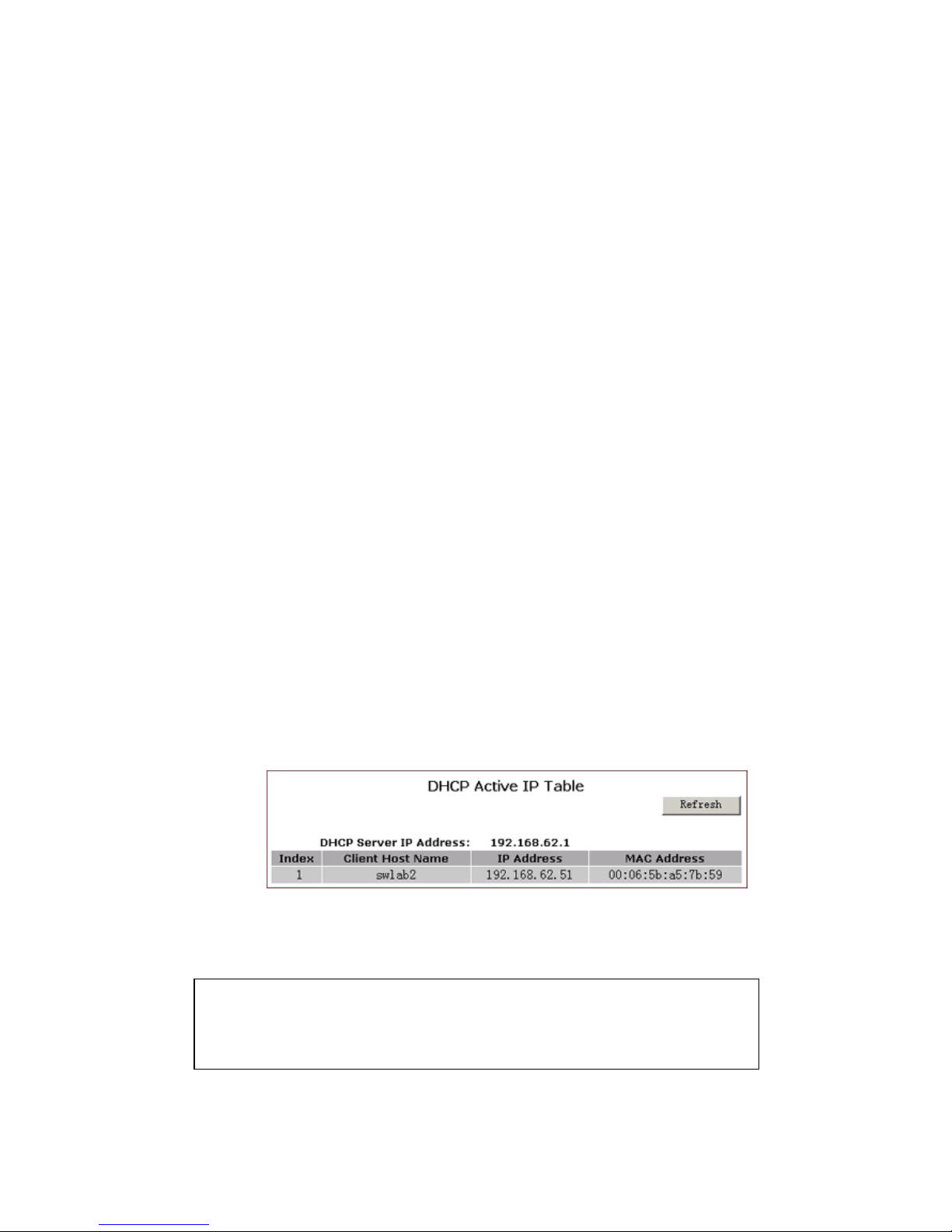
If you want to find out the information about PCs that have been
assigned IP addresses by the DHCP server, click Display DHCP
Table.
DHCP Server IP Address, Client H ost Name, IP Address and
MAC Address for each active client PC will be listed out in the
table, seen in FIGURE 4-19:
FIGURE 4-19: DHCP Active IP Table
Optional. Click Refresh to obtain the most current data.
Note :
If you have enabled the DMZ and LAN features, you can also find the
relevant information in the DHCP Active IP Table for DMZ Zone and the
DHCP Active IP Table for LAN.
Page 38
38
4.8 Log
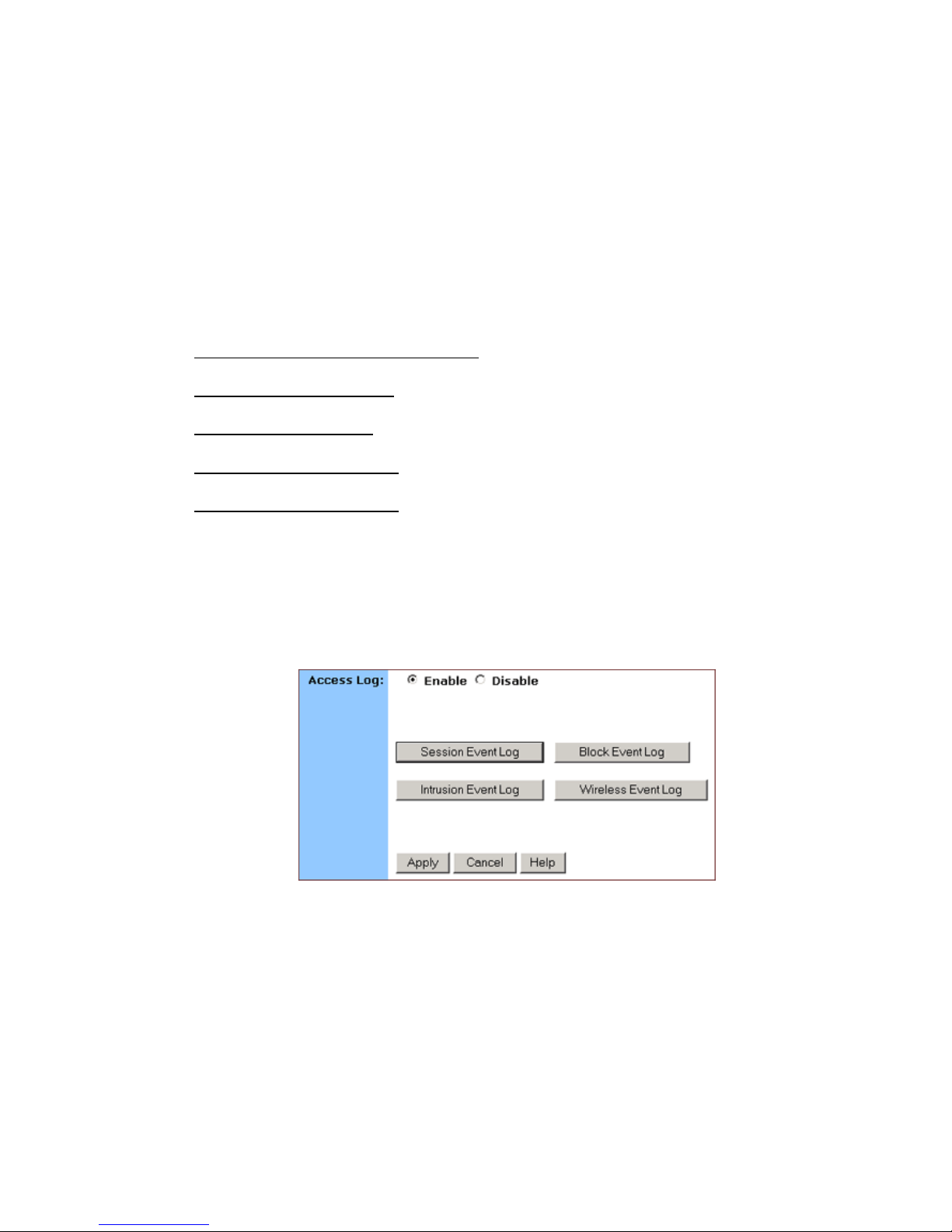
On the Log page, you can set up Access Log and view log fi le s that
record the access activity of LAN and WAN client PCs, including
Session Event Log, Block Event Log, Intrusion Event Log and
Wireless Event Log.
What do you want to do?
Set up Access Log on Your Router
View Session Event Log
View Block Event Log
View Intrusion Event Log
View Wireless Event Log
4.8.1. To Set up Acc ess Log on Your Router:
4.8.1.1. Click Log on the navigation bar.
The Log page appears, seen in FIGURE 4-20:
FIGURE 4-20: Log Page
4.8.1.2. Select Enable.
4.8.1.3. Click Apply, or click Cancel to undo your changes.
4.8.2. To Vi ew Se ssi on Event Log :
4.8.2.1. Click Session Event Log on the Log page.
Page 39
39
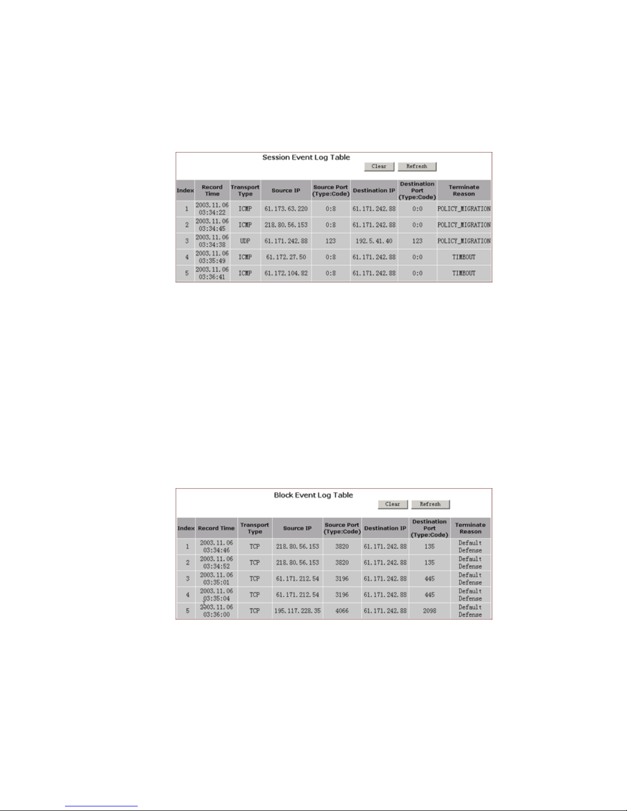
The Session Event Log Table appears, including each
session event entry information like Record Name, Transport type,
Source IP a nd so on, seen in FIGURE 4-21:
FIGURE 4-21: Sessio n Event Log Table
4.8.2.2. Optional. Click Refresh to obtain the most curr ent data.
4.8.2.3. Optional. Click Clear to delete all the log information.
4.8.3. To Vi ew B loc k Ev ent Log :
4.8.3.1. Click Block Event Log on the Log page.
The Block Event Log Table appears, including each block
event entry information like Record Name, Transport type, Source
IP and so on, seen in FIGURE 4-22:
FIGURE 4-22: Block Event Log Ta bl e
4.8.3.2. Optional. Click Refresh to obtain the most curr ent data.
4.8.3.3. Optional. Click Clear to delete all the log information.
4.8.4. To Vi ew Int r usi on Ev ent Lo g:
Page 40
40
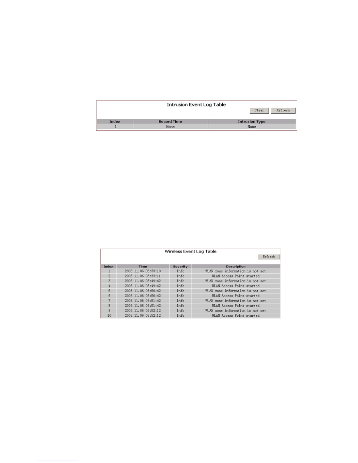
4.8.4.1. Click Intrusion Event Log on the Log page.
The Intrusion Event Log Table appears, including each
intrusion event entry’s Record Name and Int r us ion Type , seen in
FIGURE 4-23:
FIGURE 4-23: Intrusi on Event Log Table
4.8.4.2. Optional. Click Refresh to obtain the most curr ent data.
4.8.4.3. Optional. Click Clear to delete all the log information.
4.8.5. To Vie w Wireless Event Log:
4.8.5.1. Click Wireless Event Log on the Log page.
The Session Event Log Table appears, including each
wireless event entry’s Time, Severity and Description, seen in
FIGURE 4-24:
FIGURE 4-24: Wireless Event Log Table
4.8.5.2. Optional. Click Refresh to obtain the most curr ent data.
4.8.5.3. Optional. Click Clear to delete all the log information.
4.8.6. To Disable Acce ss Log on You r Router :
4.8.6.1. On the Log page, click Disabled next to Access Log.
4.8.6.2. Click Apply.
Page 41
41
4.9 Statistics
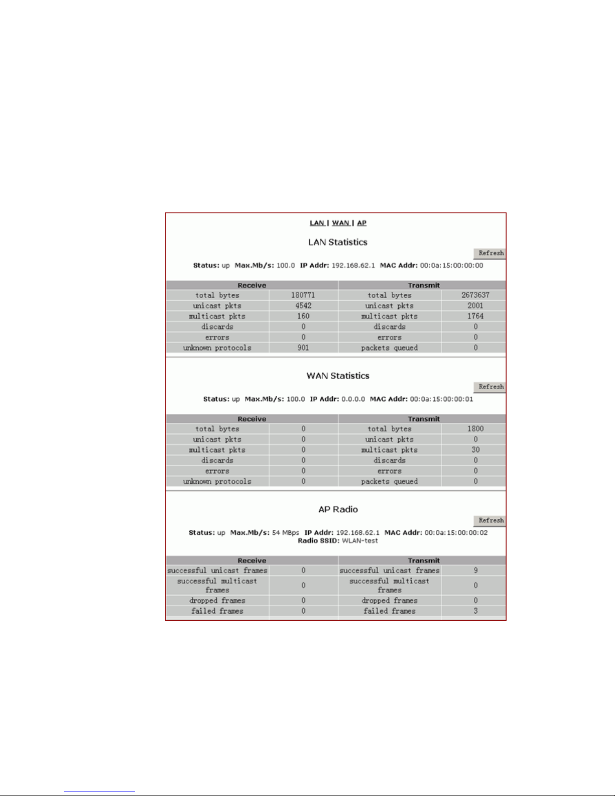
On the Statistics page, you can vie w the statistics information of LAN,
WAN and AP (Acces s Point) Radio por ts, i nclu ding Status,
Max.Mb/s, IP Addr and MAC Addr, Receiv e data and Transmit data.
You can click Statistics on the navig at ion bar, and then the Statistics
page appears, seen in FIGURE 4-25:
FIGURE 4-25: Statistics Page
4.9.1. The Statistics page includes three parts:
4.9.1.1. LAN Statis tics: Lists out the data on the LAN port .
4.9.1.2. WAN Statistics : Lists out the data on the WAN port.
Page 42

42
4.9.1.3. AP Radio : L is ts out the data on the Access Point’s radio.
Note :
You ca n also c lick Re fres h in any part abov e to obtain th e m o s t c urre nt
data.
Page 43
43
5. Advance d Function
In this chapter, you will learn how to use the advance d
administr ative functions that th e Company AP Router provides,
including Virtual Server, Filters, IP/URL Block, Special Apps,
DMZ Host, MAC Clone, Dynamic DNS, Proxy DNS and SNMP.
The Web-bas ed Administration Tool provides you some advanced
services on t he Advanced Function navigation bar, such as Filtering
and cloning your MAC addresses.
In most cases, basic functions are Okay. If you want to set the
advanced configuration, you will need to toggle to the Advanced
Function navigation bar first.
5.1. To Toggle between Basic Functio ns and
Advanced Func tions:
5.1.1. To toggle to the Advanced window, click Advanced on the
right side of the Basic window, seen in FIGURE 5-1:
FIGURE 5-1: Advanced Button on the Basic Window
5.1.2. Once you are already in the Advanced window, click Basic
on the right side of the Advan c ed window to return to the Basic
Window, seen in FIGURE 5-2:
FIGURE 5-2: Advanced Button on the Basic Window
Page 44
44
5.2 Virtual Servers
In some situati ons, you might w ant users on the Internet to be able
to acce ss servers on your LAN, such as an F TP S erver, Te lnet
Server or Web Server. Such remote services are accomplished by
creating Virtual Server.
Each virtual server has its own IP address and shares a single public
IP address . It is defined by the Protoc ol type (TCP, UDP or Both)
and a TCP/UDP/Both port number. Only the enabled virtual servers
can be accessed by remote users over the Internet.
What do you want to do?
Set up a Client PC on the LAN as a Virtual Server
Delete Virtual Servers on the LAN
5.2.1. T o Set up a Client PC on th e LAN as a Virtua l Serv er:
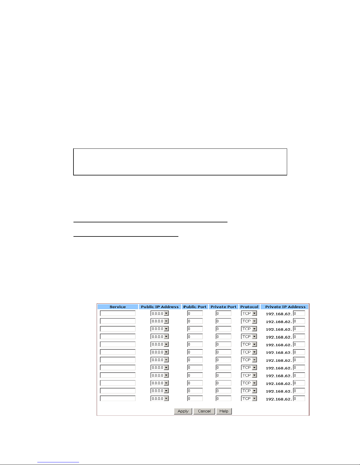
5.2.1.1. On the Advanced navigation bar, click Virtual Servers.
The Virtual Servers page appears with a list of existing virtual
servers, seen in FIGURE 5-3:
Note :
Configuring virtual ser vers may cause filters to be automat ically created
on the Filters pag e.
Page 45
45
FIGURE 5-3: Virtual Servers Page
5.2.1.2. If you have enabled DMZ and your Gateway is not
configured to retrieve an IP address automatically, sel ect either
of the following options from the Choose Interface drop-down
list:
(1) External – Internal: To set up Virtual Serve r in you r LAN
network.
(2) External – DMZ: To se t up Vi rt ua l Serv ers in your DMZ
network.
5.2.1.3. If you are using the Windows XP operating system, type
a remote service name in the Service box.
5.2.1.4. Select a Public IP Address from the drop-down list.
FIGURE 5-4: Well-know Ports
Note :
It is only available for client PCs using Windows XP. Because Windows XP
takes an adv antage of the UPnP (Universal Plug and Pl ay) feature of the
Company AP Router, it allows c lient PCs that support U PnP to identify
the router automatically.
Note :
The IP Address of a DMZ host will not appear in the list.
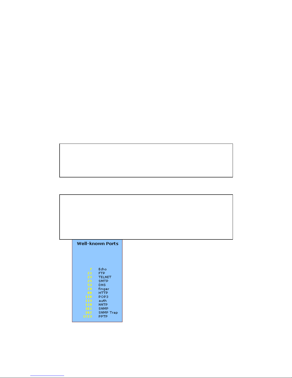
Type a port number in the Public Port and Private Port boxes,
such as 80 for HTTP. For help on which port to choose, refer
to Well-known Ports on the right of the page, seen in FIGURE
5-4:
Page 46

46
.
5.2.1.5. Select one of TCP, UDP and Both from the Protocol
drop-down list.
5.2.1.6. Type a local IP address of the server PC on the LAN in
the Private IP Address box.
5.2.1.7. When you have completed editing all the settings, click
Apply, or click Cancel to undo your changes.
5.2.2. T o Delet e Virtual Servers on the LAN:
5.2.2.1. On the Advanced navigation bar, click Virtual Servers.
A list of existing virtual servers appears.
5.2.2.2. For any virtual server you want to delete, select 0.0.0.0
from the Public IP Address drop- down list.
5.2.2.3. Click Apply.
Notes :
Public Port is the TCP/UDP/Both port number used by the server PC on
the WAN. It is also called the external port number bec au se this port
number is visible to the users on the Intern et .
Private Port is the TCP/UDP/ Both port number used by the server PC on
the LAN. The design ated Public P or t will be translated into this internal
port number
Page 47

47
5.3 Filters
On the Filters page, you can set up f ilters that can selectively al lo w
traffic to pass in and out of your network. The Company AP Router
comes with 9 fact ory default filters for you.
In addition t o 9 default filt ers, some fil ters may be cr eated
automatically to allow Virtual Servers or Special Applications to
function.
We strong ly recommend that yo u choose an empty ro w when you
want to set up new f i lters, becaus e overwriting or deleting these
filters may cause some services to be disabled, for example, your
client PCs m ay NOT be able to access the Internet.
Note – If you have overwritten or deleted the fac tory default filters,
you can retrieve them at a later time using the Restore Factory
Defaults function on the Tools page. For deta iled instructions, see To
Restore the Factory Default Configuration.
What do you want to do?
Set up a Port Filter i ng or Raw IP Filter
Delete a Port F ilter ing or Raw IP Filter
5.3.1. T o Set up a Port Filtering or Raw IP Filter:
5.3.1.1. On the Advanced navigation bar, click Filters.
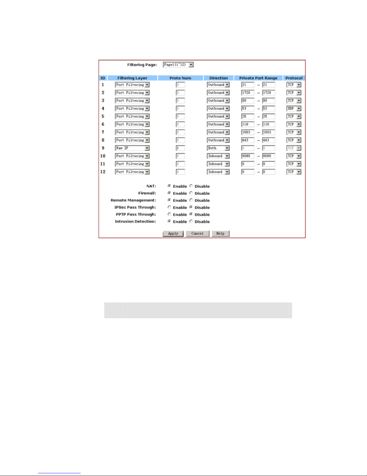
The Filters page appears, seen in FIGURE 5-5:
Page 48
48
FIGURE 5-5: Filters Page
5.3.1.2. Select an option from the Filtering Page drop-down list:
1~12, 13~24, 25~36.
5.3.1.3. If you select Port Filtering from the Filtering Layer
drop-down list, do the following action:
5.3.1.3.1. Select a traffic direction from the
drop-down list: Inbound, Outbound and
Both.
5.3.1.3.2. Type the start port number and end port
number that you want t o allo w in the Private
Port Range boxe s.
5.3.1.3.3 . Sele ct a p rotocol type from the drop-down
list: TCP, UDP and Both.
5.3.1.4. If you select Raw IP from the Filtering Layer drop-down
list, do the following action:
Page 49
49
5.3.1.5. Optional. Select Enable or Disable for the following
additional filterin g opt ions:
Paramet
er
Description
NAT
Allows you to set up NAT (Network Access
Translation).
Firewall
Allows you to protect your network with a
firewall.
Remote
Manage
ment
Allows you to access your router’s
Web-based A dm i ni strati on Tool through your
WAN connection.
IPSec
Pass
Through
Allows you to use IP Security Pass Through.
PPTP
Pass
Through
Allows you to use PPTP (Point-to-Poin t
Tunneling Protocol), used to enable VPN
sessions.
Intrusion
Detect
Allows you to detect and record intrusion
attempts into your network.
5.3.1.6. When you have completed editing all the settings, click
Apply, or click Cancel to undo your changes.
5.3.1.4.1. Type an IP Protocol Number in the P roto
Num box.
5.3.1.4.2. Select a traffic direction from the
drop-dow n list : Inbound Outbound and
Both.
5.3.1.4.3. Select an option from the Protocol
drop-dow n list : TCP, UDP and Both.
Note - It ranges from 0 to 255, but can not b e 6 (TCP)
or 17 (UDP); otherwise, this port filter will not work.
Page 50

50
5.3.2. To De let e Filt ers:
You can delete any existing Port Filtering or Raw IP filer, but make
sure that you are deleting an unwanted one, oth erwise deleti ng t he
filters associated with Virtual Servers or Special Applications may
cause to services to collaps e down.
5.3.2.1 . To De lete a Por t Filte ring Filter :
5.3.2.1.1. On the Filters page, for any Raw IP filter you want to
delete , typ e 0 in the Privat e P ort Rang e boxes.
5.3.2.1.2. Click A pp ly.
5.3.2.2 . To De lete a Ra w IP Filter :
5.3.2.2.1. On the Filters page, for any Raw IP filter you want to
delete, type 0 in the Prot o N um box.
5.3.2.2.2. Click Apply.
Page 51
51
5.4 IP/URL Block
On the IP/URL Block page, you can create filters that can selectiv ely
block users from specific IP addresses and domain names to pass in
and out of your network. The Company AP Router prov ides t wo
ways of blocki ng user s:
IP Block: Allows you to block a single IP address or a range of IP
addresses.
URL Block: Allows you to block up to 36 domain names.
Note – This IP/URL Block feature will block in both directions from
specified IP addresses or domain names.
What do you want to do?
Block a Single IP Addres s
Block a Range of IP Address
Block a Spec ific Domain Name
Delete a Specific or All IP Blocks
Delete a Specific or All URL Blocks
5.4.1. T o Block a Sing le IP Address:
Do either of the following:
5.4.1.1. Click IP/URL Block on the Advanced navigation bar.
5.4.1.2. If you are on the URL Block page, select IP Block on the
upper of the page.
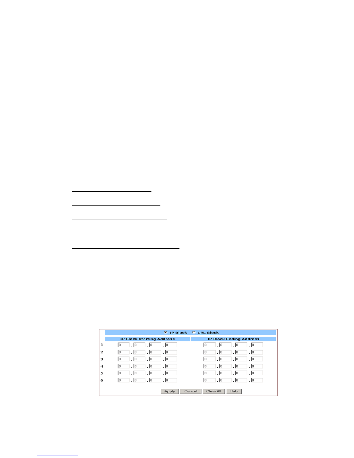
The IP Block page appears, seen in FIGURE 5-6:
FIGURE 5-6: IP Block Page
Page 52

52
5.4.1.3. In Line 1 – Line 6, type the same IP addresses in both IP
Block Starting Address and IP Block Ending Address boxes
respectively.
5.4.1.4. Optional. You can click Clear All to conveniently delete
all the existing IP addresses and then do Step 2.
5.4.1.5. When you have completed editing all the IP addresses
you want to block, click Apply, or click Cancel to undo your
changes.
5.4.2. T o Block a Range of IP Address:
5.4.2.1. Do either of the following:
Click IP/URL Block on the Adv anced navigation bar.
If you are on the URL Block page, select IP Block on the
upper of the page.
The IP Block page appears, seen in FIGURE 4-6.
5.4.2.2. In Line 1 – Line 6, type the different IP addresses in both
IP Block Starting Address and IP Block Ending Address boxes
respectively.
5.4.2.3. Optional. You can click Clear All to conveniently delete
all the existing IP addresses and then do Step 2.
5.4.2.4. When you have completed editing all the IP addresses
you want to block, click Apply, or click Cancel to undo your
changes.
5.4.3. T o Block a Specific Domain Name:
5.4.3.1. Click IP/URL Block on the advanced navigation bar.
The IP Block page appears, seen in FIGURE 5-6.
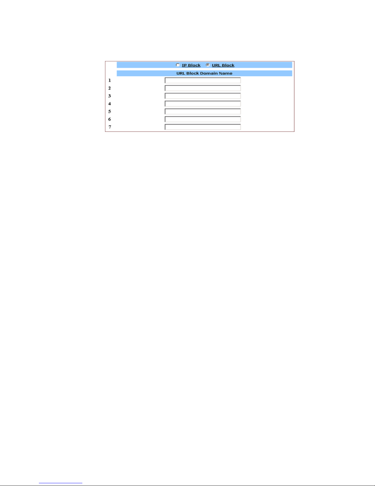
5.4.3.2. Select URL Block on the IP Block page.
The URL Block page appears, seen in FIGURE 5-7:
Page 53
53
FIGURE 5-7: URL Block Page
5.4.3.3. In Line 1 – Line 36, type the URLs you want to block.
5.4.3.4. Optional. You can click Clear All to conveniently delete
all the existing URLs and then do Step 2.
5.4.3.5. When you have completed editing all the domain names
you want to block, click Apply, or click Cancel to undo your
changes.
5.4.4. T o Delet e a Specific or All IP Blocks:
5.4.4.1. On the IP Block page, do either of the following:
For any IP block you wa nt t o delete , type 0.0.0.0 in both IP Block
Starting Address and IP Block Ending Address boxes respectively.
If you want to delete all IP blocks, click Clear All.
5.4.4.2. Click Apply.
5.4.5. To Delete a Specific or All UR L Blocks:
5.4.5.1. On the URL Block page, do either of the following:
For any domain name block you want to delete, clear out the URL in
the box.
If you want to delete all URL blocks, click Clear All.
5.4.5.2. Click Apply.
Page 54

54
5.5 Special Apps
On the Special Ap ps page, you can authorize certain ports to
communic ate with PCs outside yo ur network. I t may be necessar y
for mul t i-session applications, such as online games and voice
conferencing.
There are two ways of set up new sp ecial applications on your
router:
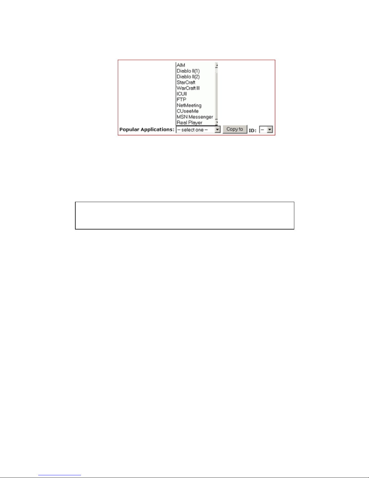
Popular Application Copy: Allows you to select one of frequently
used appl ications from the Pop ular Applications d rop-down list and
copy it to your Spec ial Application Table. Available opt ions are AIM,
Diablo II (1), Diablo II (2), StarCraft, StarCraft III, ICUII, FTP,
CUseeMe, MSN Messenger and Real Player.
Man ua l Conf igur atio n: If the a ppl icat ion you wa nt to conf igur e is not
in the Popular Applications list, you can configure its settings
manually.
Before configuring a new special application, would you please
check the list of those popula r applications first? If it is alread y in
the list, we recom mend that you us e the Popular Applicat ion Copy
unless you know exactly which settings to choos e.
What do you want to do?
Copy a Popular App lication to a Specific Line
Configure a Special Application Manually
Delete Special Applications
5.5.1. T o Copy a Popular Applicatio n to a Specific Line:
5.5.1.1. On the Advanced navigation bar, click Special Apps.
The Popular Applications list appears on the Special Apps
page, seen in FIGURE 5-8:
Notes
Configuring special applications may cause filters to be automat ically
created on the Filters page.
The Company AP Rou ter provides two factory default special appli cations
for FTP and Ne tMeeting, if you overwrite them or any other existing
application, they will not work.
Page 55
55
FIGURE 5-8: Popu la r A pplications List
5.5.1.2. Select an option from the Popular Applications drop-down
list, including AIM, Diablo II (1), Diablo II (2), StarCraft, StarCraft III,
ICUII, FTP, CUseeMe, MSN Messenger and Real Player.
Select a specific line number from the ID drop-down list.
5.5.1.3. Click Copy to.
5.5.1.4. The selected application’s c onf igurat ion is added to
your Special Applications Table on the upper of the page.
5.5.1.5. When you have completed editing all the settings, click
Apply, or click Cancel to undo your changes.
5.5.2. T o Confi gure a Special Applicati on Manua lly:
5.5.2.1. On the Advanced navigation bar, click Special Apps.
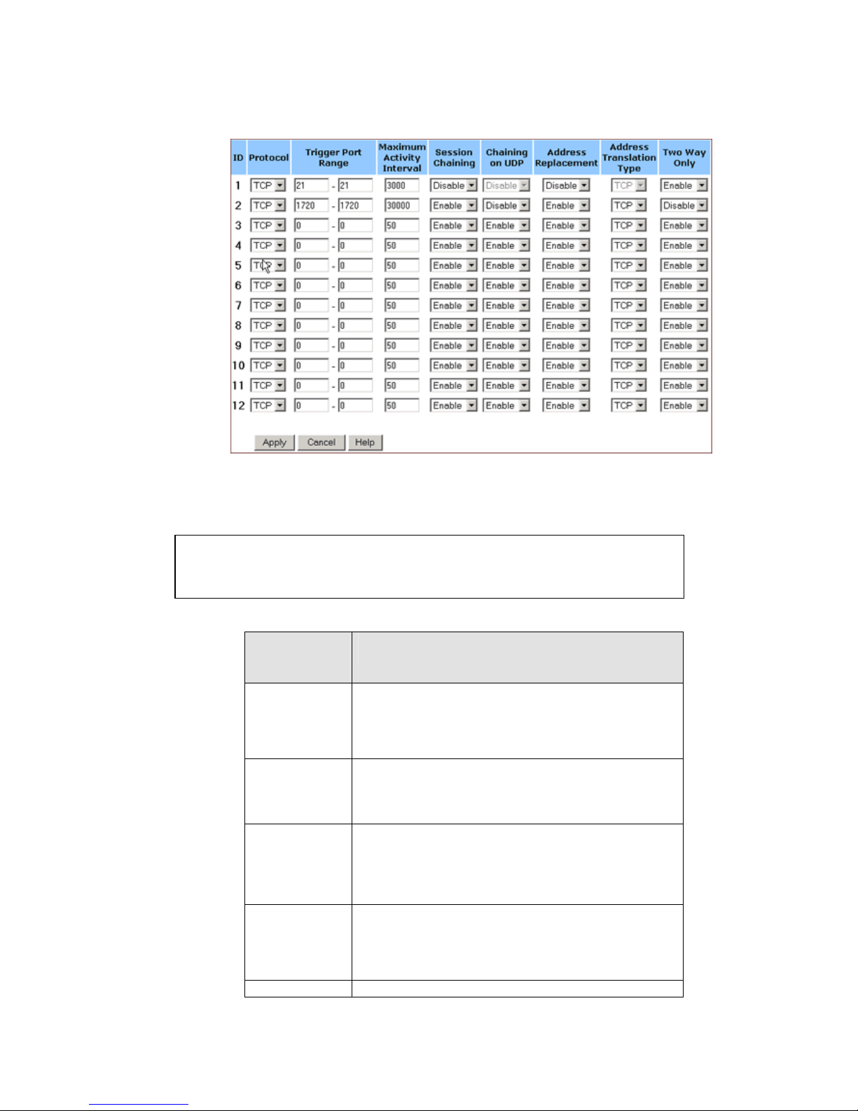
5.5.2.2. The Special Apps page appears, seen in FIGURE 5-9:
Note :
Make sure the specified ID presents an empty line unless you want to
overwrite an existing application.
Page 56
56
FIGURE 5-9: Special Apps Page
5.5.2.3. Select a line corresponding to a specific ID.
Enter the following configuration information:
Paramet
er
Description
Protocol
Specifi es the communication protocol used
by the appl i c at i on.
Avail able options ar e TCP, UDP and Both.
Trigger
Port
Range
Range of ports used for outg oi ng traffic. It
will trigger the Gateway to accept certain
incoming requests.
Maximu
m
Activity
Interval
Maximum num ber of mili seco nds aft er the
port trigger function, within which incoming
requests will be accepted.
Session
Chaining
Allows you to select either Enable or Disable.
Specifi es whether d yn amic sessi on s can be
chained, allowing mul ti-session triggering.
Chaining
Allows you to select Enable or Disable only
Note :
Make sure you have selected an empty line unless you want to overwrite
an existing application.
Page 57

57
on UDP
when Session Chaining is enabled.
Specifi es wheth er the sessio n chai ni ng is
allowed on UDP.
Address
Replace
ment
Allows you to select Enable or Disable only
when Chaining on UDP is enabled.
Specifies wh ether bi nary ad dres s
replacement should be performed.
Address
Translati
on Type
Allows you to select TCP or UDP only when
Address Replacement is enabled.
Specifi es wheth er addr ess tran slati on is
performed on TCP or U DP packets.
Two
Way
Only
Allows you to select either Enable or Disable.
Specifi es that a new session is allowed to be
initiated from the same remote host.
5.5.2.4. When you have completed editing all the settings, click
Apply, or click Cancel to undo your changes.
5.5.3. To De let e Speci a l Appli c atio n s:
5.5.3.1. On the Special Apps page, for any application you want
to delete, type 0 – 0 in th e Trig ge r Port Range box.
5.5.3.2. Click Apply.
Page 58
58
5.6 DMZ Host
On the DMZ Host page, you can expose one or more client PCs in
your network to th e I nternet. It is oft en used f or online gam es t hat
require uns t ric t ed two-way communications .
The total numb er of D MZ (Demilitarized Zone) host s you can have
depends on how many Global Addresses you have configured on
the Global A d dress page. For ex am ple, if you have defined 5 Global
Addresses (including the defaul t IP), you are limited to 5 D MZ h osts.
Since the maximum number of Globa l Addresses is 8, the total
number of DMZ hosts you can conf ig ure is als o 8.
What do you want to do?
Designate a PC in Your Net work as a DMZ Host
Delete DMZ Hosts
5.6.1. T o Desig nate a P C in Your Network as a DMZ Ho st:
5.6.1.1. On the Advanced navigation bar, click DMZ Host.
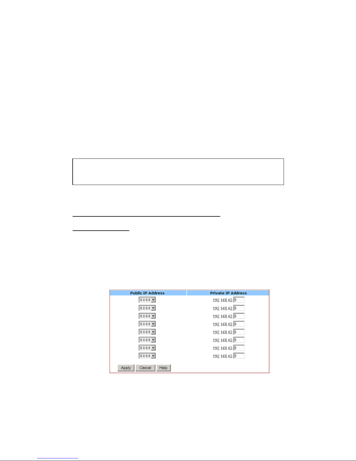
The DMZ Host page appears, seen in FIGURE 5-10:
FIGURE 5-10: DMZ Host Page
5.6.1.2. Select a Public IP Address from the drop-down list.
5.6.1.3. Type the IP address of a PC in your network that you
want to designate as a DMZ Host in the Private IP Address box.
Caution :
Once a PC in your network is designated as DMZ host, it will not have any
firewall protection.
Page 59

59
5.6.1.4. When you have completed editing all the settings, click
Apply, or click Cancel to undo your changes.
5.6.2. To De lete D MZ Hos ts:
5.6.2.1. On the DMZ Host page, for any DMZ host you want to
delete, sele c t 0.0.0.0 from the Public IP Address drop-down list.
5.6.2.2. Click Apply.
Page 60
60
5.7 MAC Clone
If your ISP restricts services at a PC level, using MAC Clone, you
can copy a PC MAC (Media Ac cess Control) address to the router.
Then what stor y wil l begin? The router will appear as a s ingle PC,
and multiple PCs in your network will access the Inter net via this
“Single PC”.
5.7.1. To Clone the MAC Address:
5.7.1.1. On the Advanced navigation bar, click MAC Clone.
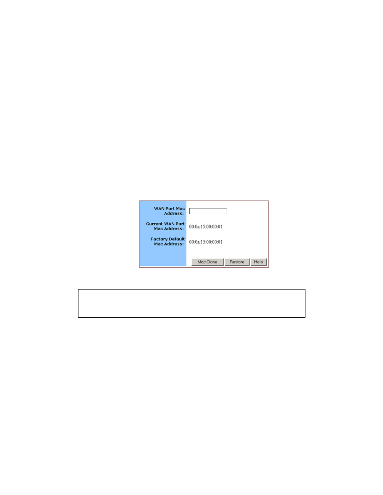
The MAC Clone page appea rs with the current WAN port
address and the factory default MAC address for your
convenience, seen in FIGURE 5-11:
FIGURE 5-11: MAC Clone Page
5.7.1.2. Click Mac Clone, or click Restore to retrieve the default
settings.
Note :
You may need to use the Ethernet MAC address of the NIC (Network
Interf ace Card) that your PC is registered with your ISP.
Page 61
61
5.8 Dynamic DNS
On the Dynamic DNS page, you can tie up your domain name to a
dynamic DNS provider. Thes e providers allow yo u to associate a
static host nam e w it h a dynamic IP address, then you can connect to
the Internet with a dynamic IP addr ess and use applications that
require a static IP address.
The Company AP Router supports three dynamic DNS provid ers:
DynDNS.org
no-IP.com
no-IP.com
What do you want to do?
Configure a Dynamic DNS Server
Disable a Dynamic DN S Server
5.8.1. T o Configure a D ynamic DN S Ser ver:
5.8.1.1. On the Advanced navigation bar, click Dynamic DNS.
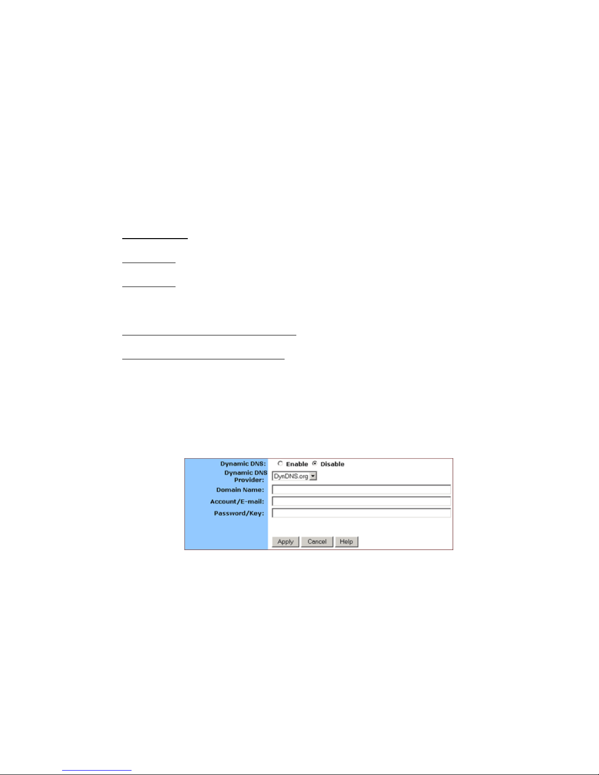
The Dynamic Server page appears, seen in FIGURE 5-12:
FIGURE 5-12: Dynamic DNS page
5.8.1.2. Select Enable next to Dynamic DNS.
5.8.1.3. Select one of DynDNS.org, no-IP.com, no-IP.com from
the Dynamic DNS Provider drop-down list.
5.8.1.4. Type your Domain Name in the box.
5.8.1.5. Type your Account or E-mail in the box.
5.8.1.6. Type your Password or Key in the box.
Page 62

62
5.8.1.7. When you have completed editing all the settings, click
Apply, or click Cancel to undo your chang es.
5.8.2. To Disable a Dynami c DNS Serv er:
5.8.2.1. On the Dynamic DNS page, select Disable next to
Dynamic DNS.
5.8.2.2. Click Apply.
Page 63
63
5.9 Proxy DNS
On the Proxy DNS page, you can map a domain name to a server IP
address. Acting as a DNS server for internal and D MZ networks, it
allows you to connect to local machines in your network without
usin g an ext ernal DNS server. It simplifie s the configur at ion and
management of your network.
What do you want to do?
Configure a Proxy DN S Server
Delete a Specific or All Proxy DNS Servers
Disable the Prox y DNS o n Your Router
5.9.1. T o Confi gure a Proxy D NS Server:
5.9.1.1. On the Advanced navigation bar, click Proxy DNS.
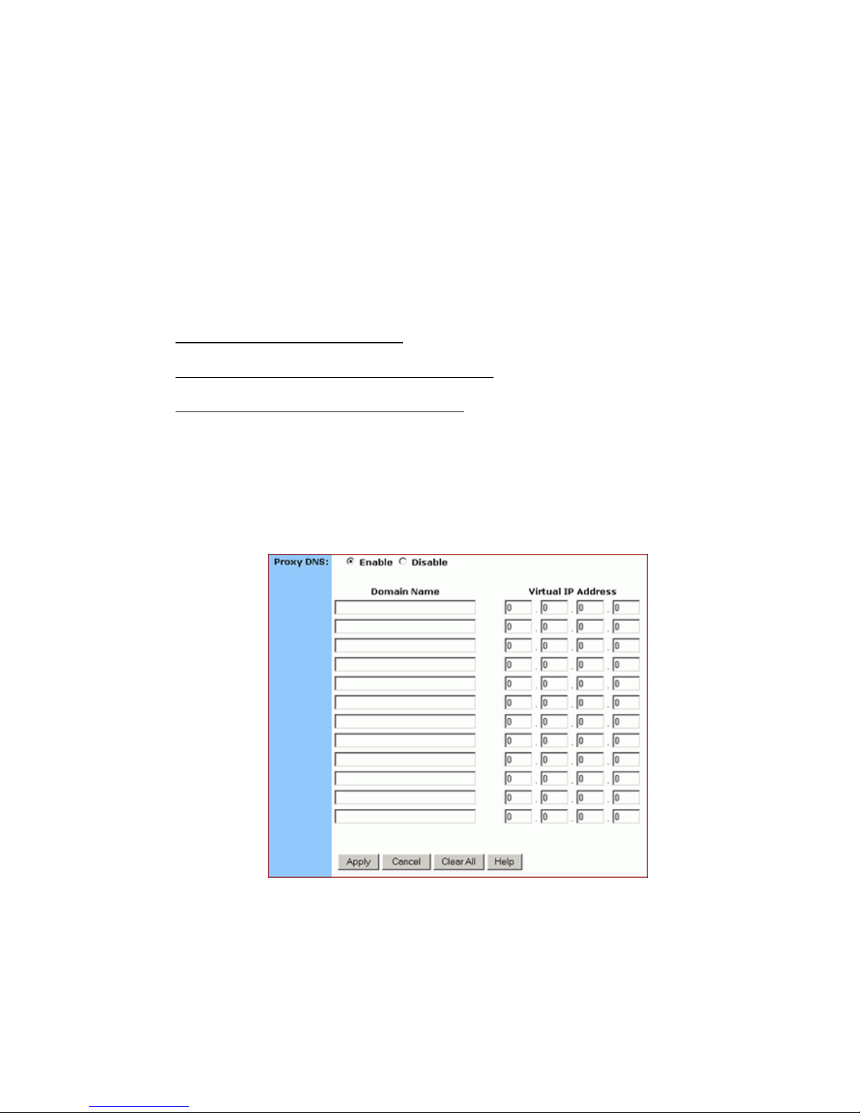
The Proxy DNS page appears, seen in FIGURE 5-13:
FIGURE 5-13: Proxy DNS Page
5.9.1.2. Select Enable next to Proxy DNS.
5.9.1.3. Type a name f or one PC in yo ur netw ork that y ou wa nt
to use as a Proxy DNS server in the Domain Name box.
Page 64
64
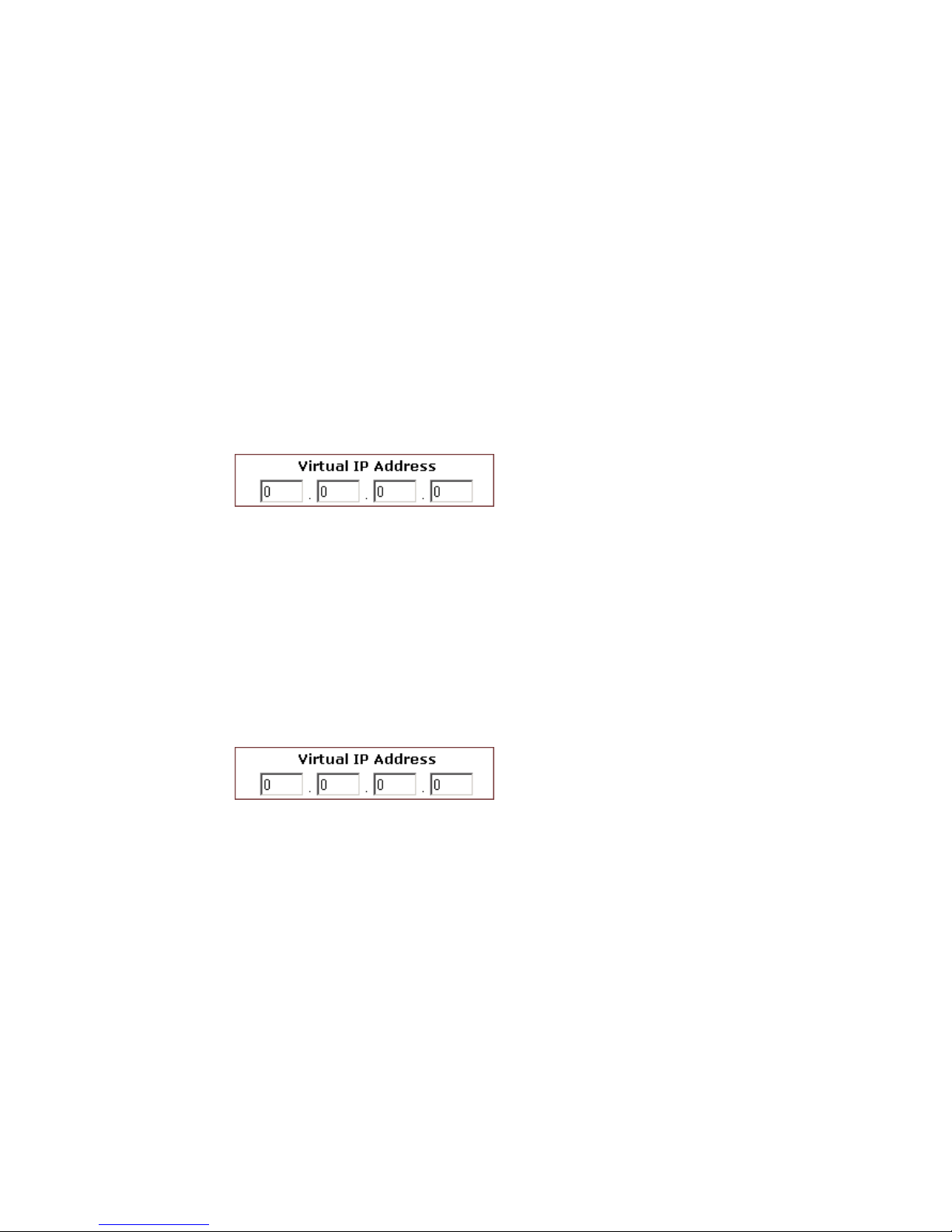
5.9.1.4. Type the IP address for the PC in the Virtual IP Address
box.
5.9.1.5. Optional. If you want to delete all the existing Proxy DNS
servers first, click Clear All and do Step 3 and Step 4.
5.9.1.6. When you have completed editing all the settings, click
Apply, or click Cancel to undo your changes.
5.9.2. T o Delet e a Spec ific or All Proxy DN S S e rvers:
5.9.2.1. On the Proxy DNS page, for any Proxy DNS server you
want to delete, type 0.0.0.0 in the Virtual IP Address box.
5.9.2.2. If you want to delete all the existing Proxy DNS servers,
click Clear All.
5.9.2.3. Click Apply.
5.9.3. T o Disable the Proxy D NS on Your Router:
5.9.3.1. On the Proxy DNS page, for any Proxy DNS server you
want to delete, type 0.0.0.0 in the Virtual IP Address box.
5.9.3.2. If you want to delete all the existing Proxy DNS servers,
click Clear All.
5.9.3.3. Click Apply.
Page 65

65
5.10 SNMP
The Si mp le Network Management Protoco l (SNMP ) is an a ppl ication
layer protocol that facilit ies the exchange of m anagement
information between network devices. It is part of TCP/IP
(Transmission Control protocol/Inter net Protocol) suite and enables
you to control and monitor the network in a simple way.
On the SNMP page, you can edit the basic Agent information and
also configure up to 6 SNMP trap re ceiver’s IP Addr e sses. When a
trap condition occurs, your router will send an SNMP trap message
to any NMS (Network Management System) specified as trap
receivers, for example, when power supply errors occur.
And mo r e over, y ou can specify different community names for
authenticating access to the management informatio n, whic h
function as embedded pass wo rds:
Read: Giv es you READ access to all the management information,
but does not allo w WRITE access.
Write: Gives you both READ and WRITE access to all the
manage me nt inform ation.
What do you want to do?
Configure Agent Information, SNMP Trap Host IP Addresses and
Community Names on Your Router
Delete an Existi ng SNMP Trap Receiver
Delete SNMP Community Names
Notes :
NMS (Network Management System) is an SNMP management
application together with the computer it runs on.
Currently the Company AP Router supports SNMPv1 (SNMP version 1)
and SNMPv2 (SNMP version 2) which have a number of features in
common except for some enhancements.
Note :
The community name definitions on your NMS must match at least one of
the above two community name definitions.
Page 66
66
5.10.1. To Confi gure Agent Inf or mati on , SNMP Tr ap Host IP
Addres se s and Com mu nity Names on Your Rout er:
5.10.1.1. On the Advanced navigation bar, click SNMP.
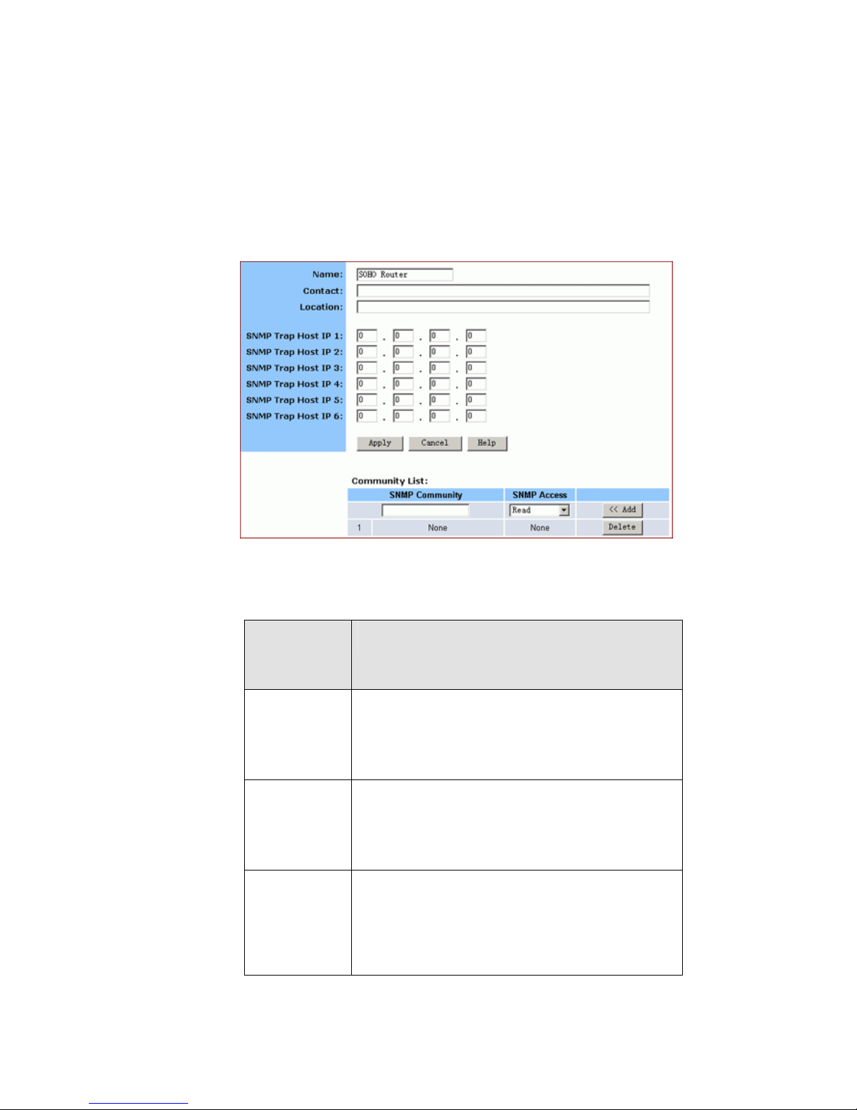
The SNMP page appears, seen in FIGURE 5-14:
FIGURE 5-14: SNMP Page
Enter the following Agent informa tion:
Paramet
er
Description
Name
Specifi es an admini strativel y-as si gne d name
for this managed node, like SOHO Router.
It is a string of the maximum 31 alph anu meric
characters.
Contact
Specifies the contact person of this managed
node, plus phone number , E m ail addres s, et c.
It is a string of the maximum of 255
alphanum eric characters.
Location
Specifi es the physical location of thi s
managed node, for example, city, address
and specific office location.
It is a string of the maximum of 255
alphanum eric characters.
Page 67
67
5.10.1.2. To send SNMP trap messages to any NMS, type up to 6
trap receiver IP addresses in the SNMP Trap Host IP Address
1 – SNMP Trap Host IP Address 6 boxes.
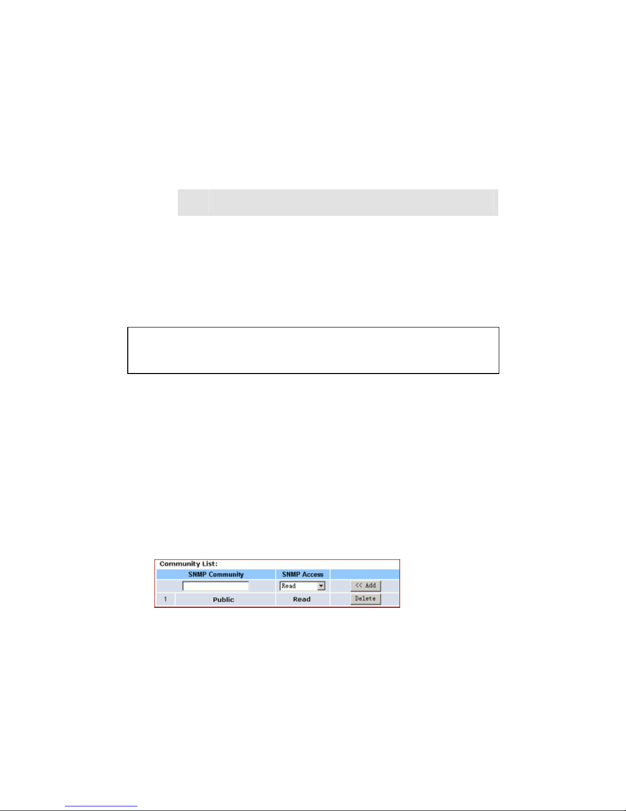
5.10.1.3. To secure SNMP with community names, do the
following a c t ion:
5.10.1.3.1. Type a string in the SNMP Community box,
like Public.
5.10.1.3.2. Select an option from the SNMP Access
drop-down list, for example, Read.
5.10.1.3.3. Click Add. If you want to add more community
names, do Step 4.1 – Step 4.3 again.
5.10.1.4. When you have completed editing all the settings, click
Apply, or click Cancel to undo your changes.
5.10.2. To Delete an Existing SNMP Trap Receiver:
5.10.2.1. On the SNMP page, for any SNMP trap receiver that you
want to delete, enter 0.0.0.0 in the SNMP Trap Host IP Address
box.
5.10.2.2. Click Apply.
5.10.3. To Delete SNMP Community Names:
5.10.3.1. On the SNMP page, for any SNMP community name
that you want to delete, click Delete in the corresponding row.
5.10.3.2. Click Apply.
Note :
Usually, we define a string of “Public” for Read acces s and “Private” for
Read-W r i t e acc es s.
Page 68

5.11 Static Routing
The Static Routing is used to configure static routes to remote networks
manually, where the route is predefined and is not supervised by the
Routing Information Protocol (RIP). It can explicitly reduce the network
traffic and speed the Internet connects for a small network.
However, it may fall into a certain disadvantage. When a static router
involves more than one Hop, if the connection to the next hop goes
down, the router cannot be aware of the invalid path and continues to
route traffic on this hop.
On the Static Routing page, you can add up to 20 static routes by
indicating:
Destination LAN IP address and Subnet Mask
Remote gateway
Hop
Router interface through which to forward the packets to the destination.
What do you want to do?
Add a New Static Route
Delete a Static Route
Note :
If the network topology changes, you may ha ve to make chang es to the static
routing tables for relevant static routes.
Page 69
5.11.1. To Add a New Static Rou te:
5.11.1.1. On the Advanced navigation bar, click Routing.
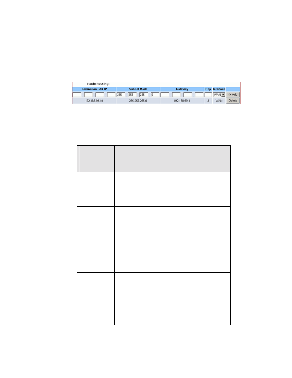
The Stati c Rout ing page appears, seen in FIGUR E 5-1 5:
FIGURE 5-15: Static Routing Page
5.11.1.2. Enter the following static route information:
Paramet
er
Description
Destinati
on LAN
IP
Speci f ies the net w ork address of the remote
LAN segm en t . For sta ndard cla s s " C" LANs,
the network address is the first 3 fields of this
Destination LAN IP, t h e 4t h f ield can be left at
0.
Subnet
Mask
Speci f ies the Subnet Mask used on th e
remote LAN segment. For clas s "C" networ k s,
the standard Network Mask is 255.255.255.0.
Gateway
Speci f ies the IP Address of th e r o uter on the
local LAN segment to which this device is
attached.
Note that it is NOT the router on the remote
LAN se gment.
Hop
Speci f ies the num ber of routers that must b e
traversed to rea c h the remote LAN segment.
Valid values are 1 to 16.
Interface
Specifies the interface through which the
router go e s to t h e n e xt hop or a particular
netw ork. Available op t ions are WAN, LAN and
DMZ.
Page 70

5.11.1.3. Click <<Add.
The new static route appears in the static routing list.
5.11.2. To Delete a Static Rou te:
5.11.2.1. On the Static Routing page, for any static route that you
want to delete, review the relevant information, seen in FIGURE 5 –
15.
5.11.2.2. Click Delete.
Page 71

6. Glossary
IEEE 802.11 Standard
The IEEE 802.11 Wireless LAN standards su bco mmitt ee, w hi ch is formulati ng
a standard for the industry.
A cces s point
An Internet working device that seamlessly connects wired and wireless networks together.
Ad hoc
An ad hoc wireless LAN is a group of computers, each with a WLAN adapter, connected as
an independent wireless LAN. Ad hoc wireless LAN is applicable at a departmental scale for a
branch or SOHO o p eration.
BSSID
A specific ad hoc LAN is called a Basic Service Set (BSS). Computers in a BSS must be
configured with the same BSSID.
DHCP
Dynamic Hos t Configuration Prot o c ol - a method in whic h IP addresses are assigned by a
server dynamically to clients on the netw ork. DHCP is us ed for dynamic IP ad dressing an d
requires a dedi cated DHCP ser ver on the network.
DSSS
Direct Sequence Spread Spectrum. This is the method the wireless adapters use to transmit
data over the frequency spectrum. An alternative method is frequency hopping. Direct
sequence spreads the data over one frequency range (channel) while frequency hopping
jumps from one narrow frequency band to another many times per second.
ESSID
An infrastructure configuration could also support roaming capability for mobile workers. More
than one BSS can be configured as an extended service set (ESS). Users wi t hin an ESS can
roam freely between BSSs while served as a continuous connection to the network wireless
stations and access points withi n an ESS must be configured wit h the same ESSID and the
same radio channel.
Ethernet
Ether net is a 10/10 0Mbps netw ork that runs over d e dicated home/office wiring.
Users must be wir ed to the network at all times to gai n access.
Gateway
A gateway is a hardware and software device that connects two dissimilar systems, such as a
LAN and a mai n f rame. In Internet ter mi n ology , a gateway i s another name fo r a r o uter.
Generally a gateway is used as a funnel for all traffic to the Internet.
Page 72

IEEE
Institute of Electrical and Electronics Engineers
Infrastructure
An integrated wireless and w ired LAN is ca l led an infra s tructure co n f iguration. Infr a s tructure i s
applicable on an enterprise scale for wireless access to a central database, or wireless
application for mo bile workers .
ISM Band
The FC C and their counterparts outs ide of the U.S . have set asi de bandwidth for unli ce nsed
use in the so-called I SM (Indus trial, Sci entific and Medic al) band. Spectrum in the vicinity of
2.4 GH z, in par ticular, is bei ng ma de av ailable worl dwid e. This prese nts a truly revolutionar y
opportunity to place convenient high speed wireless capabilities in the hands of users around
the globe.
LAN
Local A rea Networ k. A LAN is a group of c o mp uters, ea c h e quipp ed with the a ppro pr iate
network adapter connected by cable/air that share applications, data, and peripherals. All
connections are made via cable or wireless media, but a LAN does not use telephone
services. It ty pically spans a s ingle building or campus .
Network
A network is a system of computers that is connected. Data, .les, and messages can be
transmitted over this network. Net w orks may be l o c al or wide area netw orks.
Protocol
A prot ocol is a stan dardi z e d s et of rules t hat spe cify how a commu nication is to take plac e,
including the format, timing, sequencing and/ or error checking.
SSID
Service Set Ident ifier. A network ID uniq ue to a networ k . Only client s and access points that
shar e the same SSID are able to communicate with each other. T his string is case-sensi tive.
SNMP
Simple Network Management Protocol is the network management protocol of TCP/IP. In
SNMP, agents-w hich can be har dware as we ll as s oftw are-monit or the act ivity in t he various
devices on the network and report to the n etwor k c o nsole workstation. Contro l information
about each d evice is mai ntained in a s truct ure known as a manag ement information block.
Static IP addressing
A meth od of assigning IP addr es ses to clients on the netw ork. In netw orks wi th static IP
address, the network administrator manually assigns an IP address to each computer. Once a
stat ic IP address is assigned, a compu ter uses the same IP address ev e r y time it rebo ots and
logs on to the network, unless it is manually changed.
TCP/IP
Transmission Control P rotocol / Internet Protocol. TCP/IP is the pr otoco l s uite developed by
Page 73

the Advanced Research Projects Agency (ARPA). TCP governs how a packet is sequenced
for transmission the network. The term “TCP/IP” is often used generically to refer to the entire
suite of related protocols.
Transmit / Receive
The wireless thr o ughput in by tes per s econ d ( B ps) averag ed over two seconds .
WAN
Wide Area Network. A WAN consists of multiple LANs that are tied together via telephone
services and / or fiber optic cabling. WANs may s pa n a cit y , a s tate, a co untry, or even the
world.
Page 74

www.x-micro.com
 Loading...