

Page 1

WLAN 11g Broadband Router
User Guide
ver 1.0
Page 2
This product is in compliance with the essential requirements
and other relevant provisions of the R&TTE directive 1999/5/EC.
Product Name: X-Micro WLAN 11g Broadband Router
Model Name : XWL-11GRAR
MAX. OUT POWER
COUNTRY CHANNELS
INDOOR OUTDOOR
Spain
2400-2483.5 MHz 1-13 < 100 mW EIRP < 100 mW EIRP
France
2400-2454 MHz 1-8 < 100 mW EIRP < 100 mW EIRP
France
2454-2483.5 MHz 9-13 < 100 mW EIRP < 10 mW EIRP
Italy
2400-2483.5 MHz 1-13 < 100 mW EIRP < 100 mW EIRP
UK
2400-2483.5 MHz 1-13 < 100 mW EIRP < 100 mW EIRP
Netherlands
2400-2483.5 MHz 1-13 < 100 mW EIRP < 100 mW EIRP
Germany
2400-2483.5 MHz 1-13 < 100 mW EIRP < 100 mW EIRP
Austria
2400-2483.5 MHz 1-13 < 100 mW EIRP < 100 mW EIRP
Belgium
2400-2483.5 MHz 1-13 < 100 mW EIRP < 100 mW EIRP
Switzerland
2400-2483.5 MHz 1-13 < 100 mW EIRP < 100 mW EIRP
Luxemburg
2400-2483.5 MHz 1-13 < 100 mW EIRP < 100 mW EIRP
Ireland
2400-2483.5 MHz 1-13 < 100 mW EIRP < 100 mW EIRP
Portugal
2400-2483.5 MHz 1-13 < 100 mW EIRP < 100 mW EIRP
Norway
2400-2483.5 MHz 1-13 < 100 mW EIRP < 100 mW EIRP
Denmark
2400-2483.5 MHz 1-13 < 100 mW EIRP < 100 mW EIRP
Finland
2400-2483.5 MHz 1-13 < 100 mW EIRP < 100 mW EIRP
Iceland
2400-2483.5 MHz 1-13 < 100 mW EIRP < 100 mW EIRP
Greece
2400-2483.5 MHz 1-13 < 100 mW EIRP < 100 mW EIRP
Lichtenstein
2400-2483.5 MHz 1-13 < 100 mW EIRP < 100 mW EIRP
Sweden
2400-2483.5 MHz 1-13 < 100 mW EIRP < 100 mW EIRP
Page 3

FCC INFORMATION
FCC Radiation Exposure Statement
This equipment complies with FCC radiation exposure limits set forth for an
uncontrolled environment.
This equipment should be installed and operated with minimum distance
20cm between the radiator & your body.
This transmitter must not be co-located or operating in conjunction with any
other antenna or transmitter.
The equipment has been tested and found to comply with the limits for a
Class B Digital Device, pursuant to part 15 of the FCC Rules. These limits are
designed to provide reasonable protection against harmful interference in a
residential installation.
This equipment generates, uses and can radiate radio frequency energy
and, if not installed and used in accordance with the instruction, may cause
harmful interference to radio communication. However, there is no grantee that
interference will not occur in a particular installation. If this equipment dose
cause harmful interference to radio or television reception, which can be
determined by turning the equipment off and on, the user is encouraged to try to
correct the interference by one or more of the following measures:
--Reorient or relocate the receiving antenna.
--Increase the separation between the equipment and receiver.
--Connect the equipment into an outlet on a circuit different from that to which
the receiver is connected.
--Consult the dealer or an experienced radio/TV technician for help.
Notice: The Part 15 radio device operates on a non-interference basis with
other devices operating at this frequency. Any changes or modification not
expressly approved by the party responsible could void the user’s authority to
operate the device.
REGULATORY INFORMATION
X-Micro WLAN 11g Broadband Router must be installed and used in strict
accordance with the instructions. This device complies with the following radio
frequency and safety standards.
USA - Federal Communications Commission (FCC)
This device complies with Part 15 of FCC Rules. Operation is subject to the
following two conditions:
1. This device may not cause harmful interference.
2. This device must accept any interference that may cause undesired
operation.
Page 4

1
Copyright
Copyright 2006 by X-Micro Technology Corp., All rights reserved. No part of
this publication may be reproduced, transmitted, transcribed, stored in a
retrieval system, or translated into any language or computer language, in any
form or by any means, electronic, mechanical, magnetic, optical, chemical,
manual or otherwise, without the prior written permission of X-Micro
Technology Corp.
Disclaimer
X-Micro Technology Corp. makes no representations or warranties, either
expressed or implied, with respect to the contents hereof and specifically
disclaims any warranties, merchantability or fitness for any particular purpose.
Any software described in this manual is sold or licensed "as is". Should the
programs prove defective following their purchase, the buyer (and not this
company, its distributor, or its dealer) assumes the entire cost of all necessary
servicing, repair, and any incidental or consequential damages resulting from
any defect in the software. Further, X-Micro Technology Corp., reserves the
right to revise this publication and to make changes from time to time in the
contents hereof without obligation to notify any person of such revision or
change.
All brand and product names mentioned in this manual are trademarks and/or
registered trademarks of their respective holders.
Page 5

2
Index
English……………………………………………….…..………………………..P.2
German…………………….……………………………......…………………P.12
French………………………………………………………..………………….P.21
Dutch……………………………………………………………..………………P.30
Italian…………………………………………………………………............….P.39
Spanish……………………………………………………………….....………P.48
Portuguese………….....................................………………………….……P.57
Russian…………….......................................………………….……P66
Traditional Chinese……………………………………………………….……P.75
Page 6
3
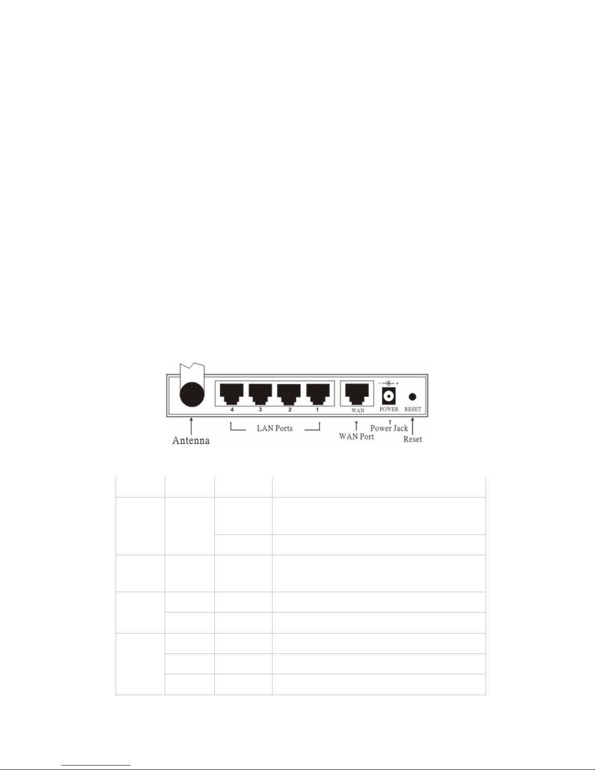
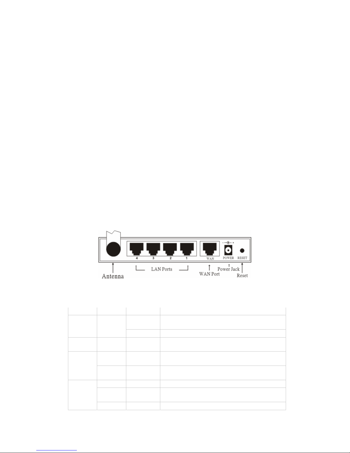
§ Connect the wireless broadband router to your network
1. Connect the power adapter to the receptor at the back panel. Plug the
power adapter into the outlet. The power LED will turn on to indicate this
proper operation.
2. Power off your cable/ DSL modem. Using an Ethernet cable to connect the
Ethernet jack located on the cable/ DSL modem and the WAN port on the
back panel of this router. After this connection, please power on your cable/
DSL modem. The WAN PORT will illuminate to indicate the proper
operation
3. Insert an Ethernet cable to the LAN port on the back panel of the router and
an available Ethernet port on the network adapter in the computer that will
be used to configure the router. The LED light of LAN port1 will illuminate to
indicate the proper connection.
4. Then, restart your computer.
5. Connect your Ethernet-quipped computers to the remaining Ethernet LAN
ports on the back panel of this router with the additional Ethernet cables.
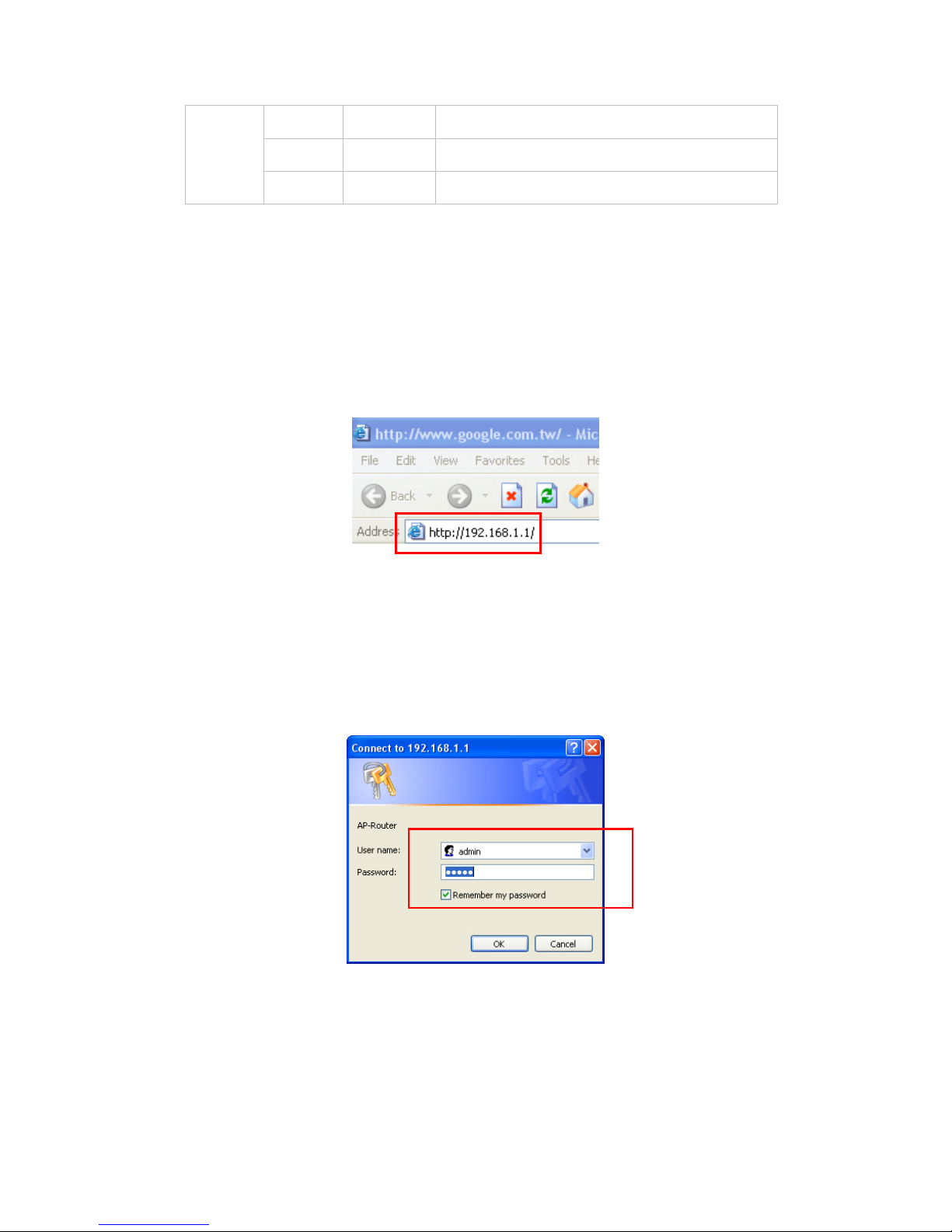
◆ Back View:
◆ LED Indicators:
LED Color Status Description
On
Indicates proper connection to power
supply.
Power
Green
OFF The unit is not receiving power
Status
Green On
Indicates that the device is
connected to the WLAN.
On Indicates connection to the WAN port
WAN
Blinking Data transmission.
On Link is established
On Blinking Packet transmit or receive activity WLAN
Off — No Link activity
Page 7
4
On Indicates connection is established.
On Blinking Data transmissions LAN
Off — No LAN connections
§ Quick Setup via Wizard
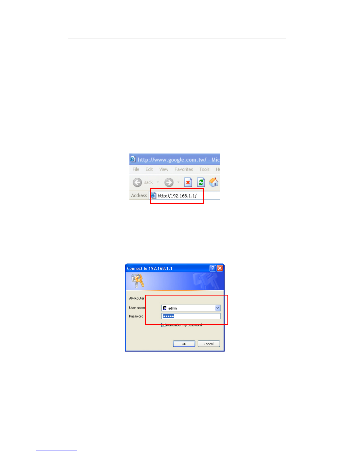
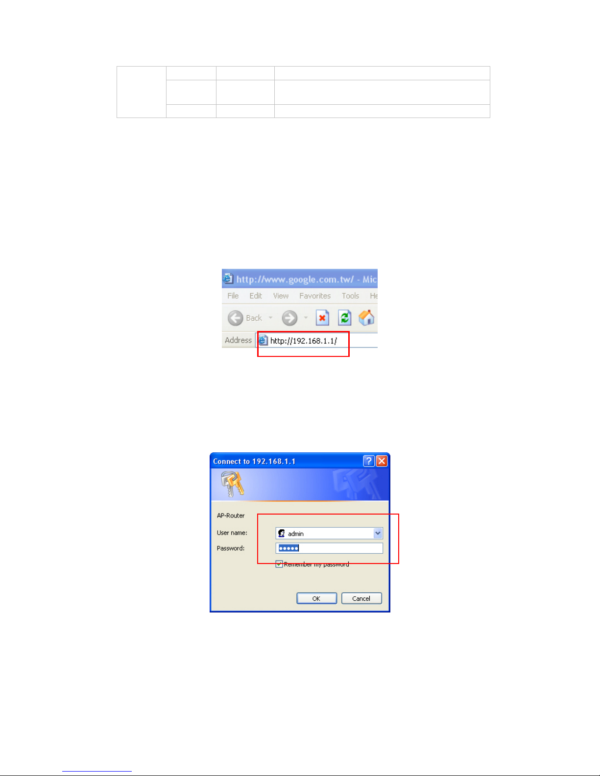
◆ Open your Web Browser
You could start to access the configuration menu anytime by opening a web
browser window by typing the IP address of this wireless router. The default
IP is 192.168.1.1.
The below window will popup. Please enter the user name and password.
Both of the default is “admin”.
Now, the main menu screen is popup.
Page 8
5
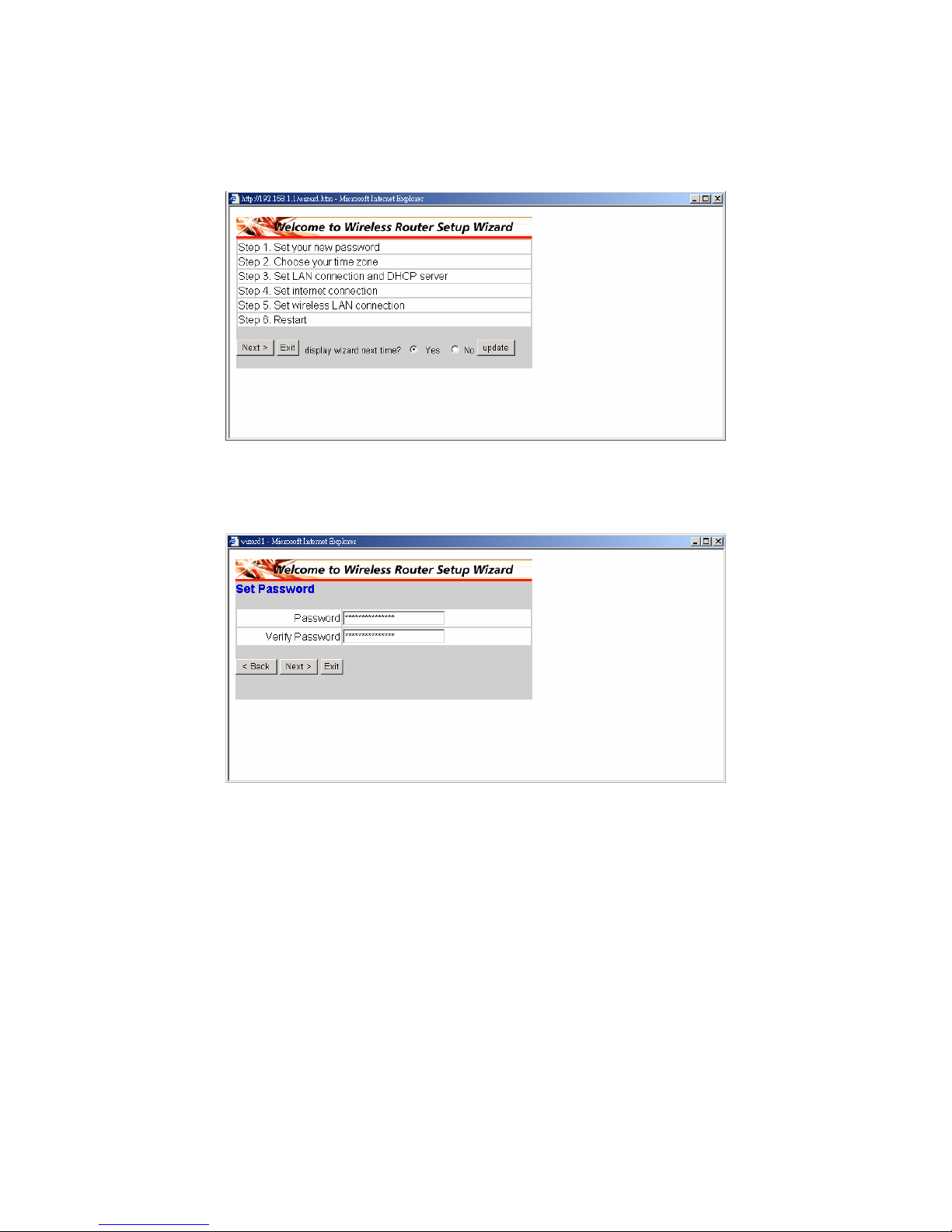
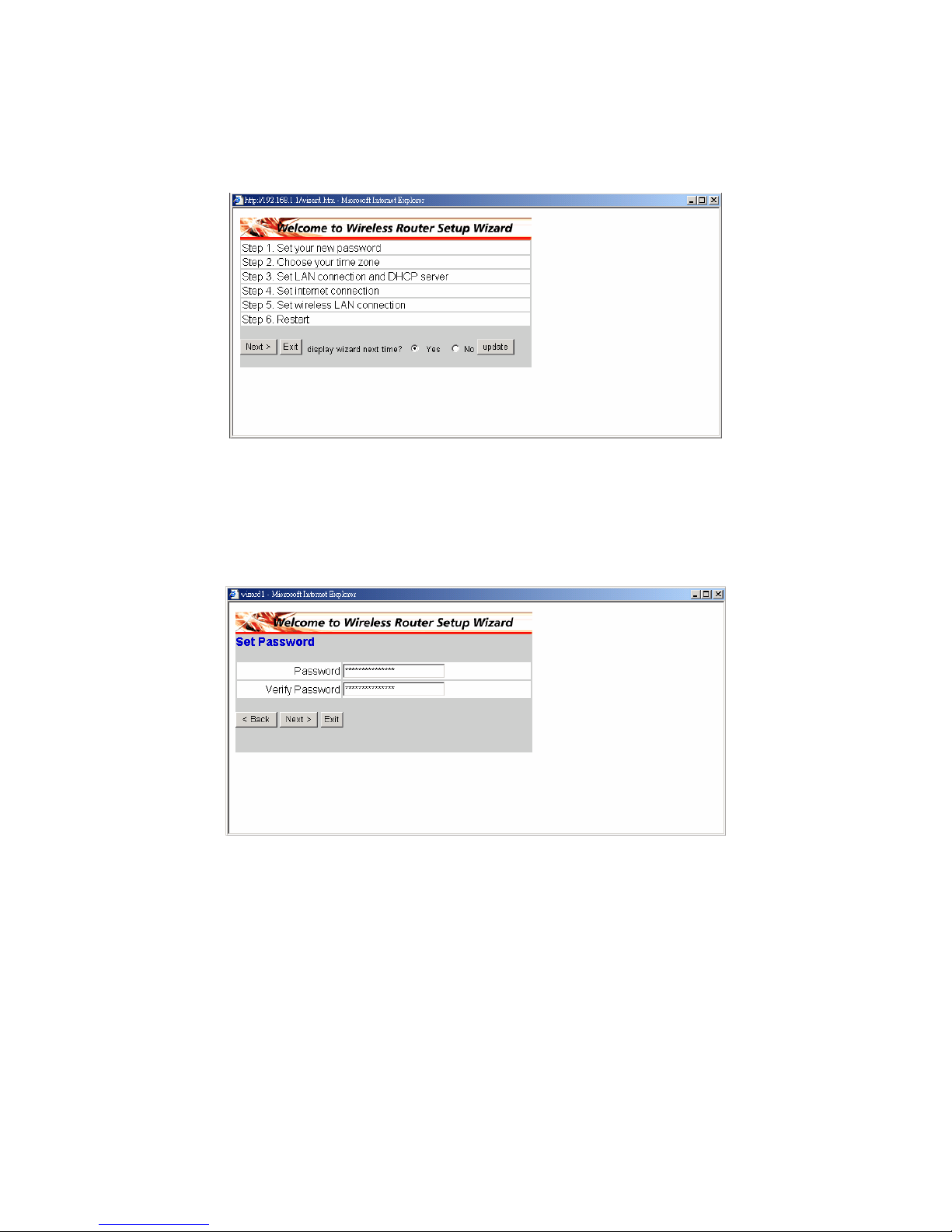
You can simply follow the step-by-step process to get your wireless router
configuration ready to run in 6 easy steps. Please click “Next” on the Setup
Wizard screen to continue.
◆ Step 1: Set your new Password
You can change the password as you like and then click “Next” to continue.
Page 9
6
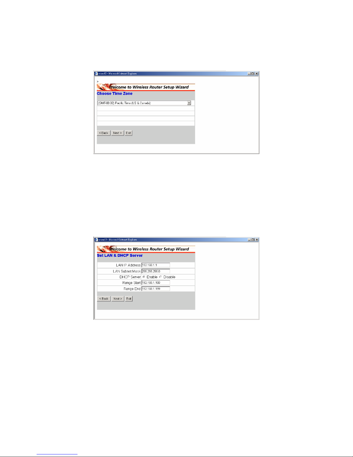
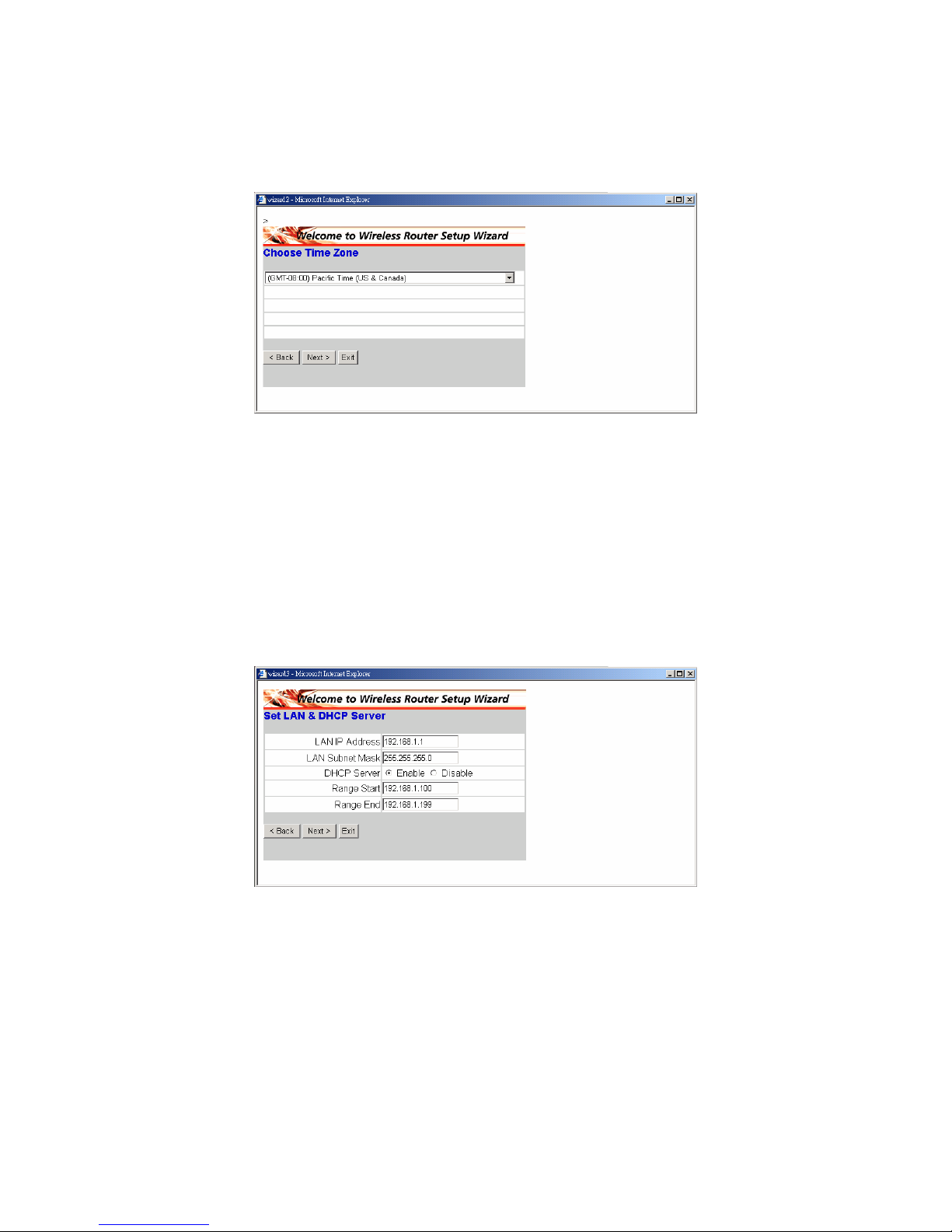
◆ Step2: Choose your time zone
Select your time zone from the drop down list. Please click “Next” to
continue.
◆ Step 3: Set LAN connection and DHCP server
Set your IP address and mask. The default IP is 192.168.1.1. If you like to
enable DHCP, please click “Enabled”. DHCP enabled is able to
automatically assign IP addresses. Please assign the range of IP addresses
in the fields of “Range start” and “Range end”. Please click “Next” to
continue.
Page 10
7
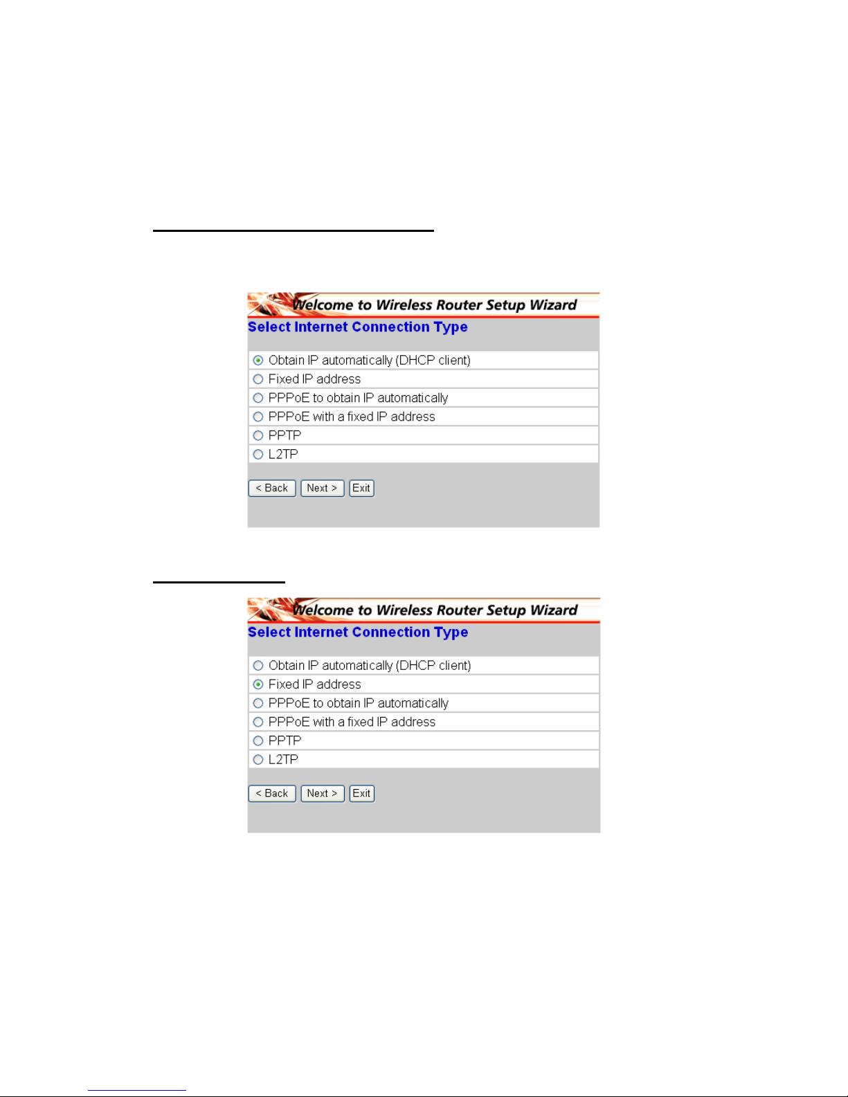
◆ Step 4: Set Internet connection
Select how the router will set up the Internet connection: Obtained IP
automatically; Fixed IP address; PPPoE to obtain IP automatically; PPPoE
with a fixed IP address; PPTP.
Obtain IP automatically (DHCP client):
If you have enabled DHCP server, choose "Obtain IP automatically (DHCP
client)" to have the router assign IP addresses automatically.
Fixed IP Address:
Page 11
8
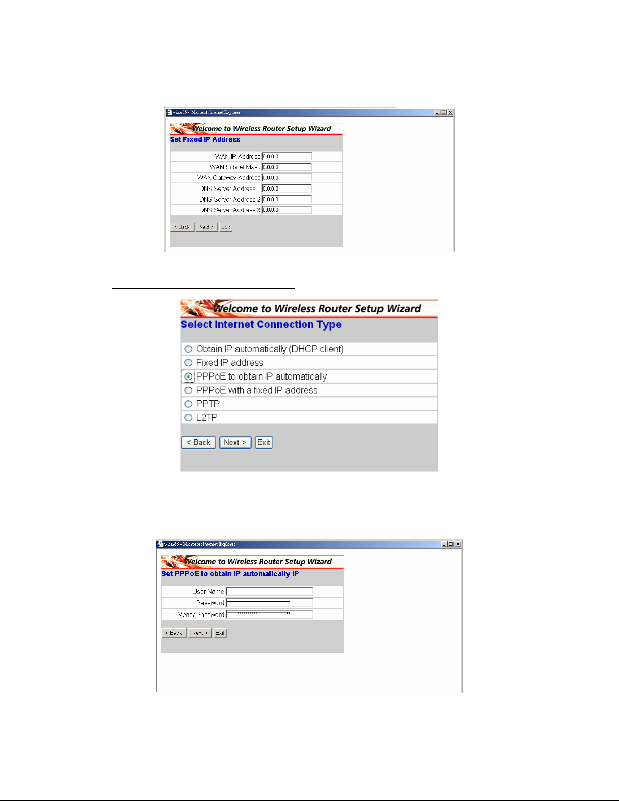
If Fixed IP address is assigned, the below screen will pop up. Please set the
WAN address and DNS server.
PPPoE to obtain IP automatically:
If connected to the Internet using a PPPoE (Dial-up xDSL) Modem, the ISP will
provide a Password and User Name, and then the ISP uses PPPoE. Choose
this option and enter the required information.
Page 12
9
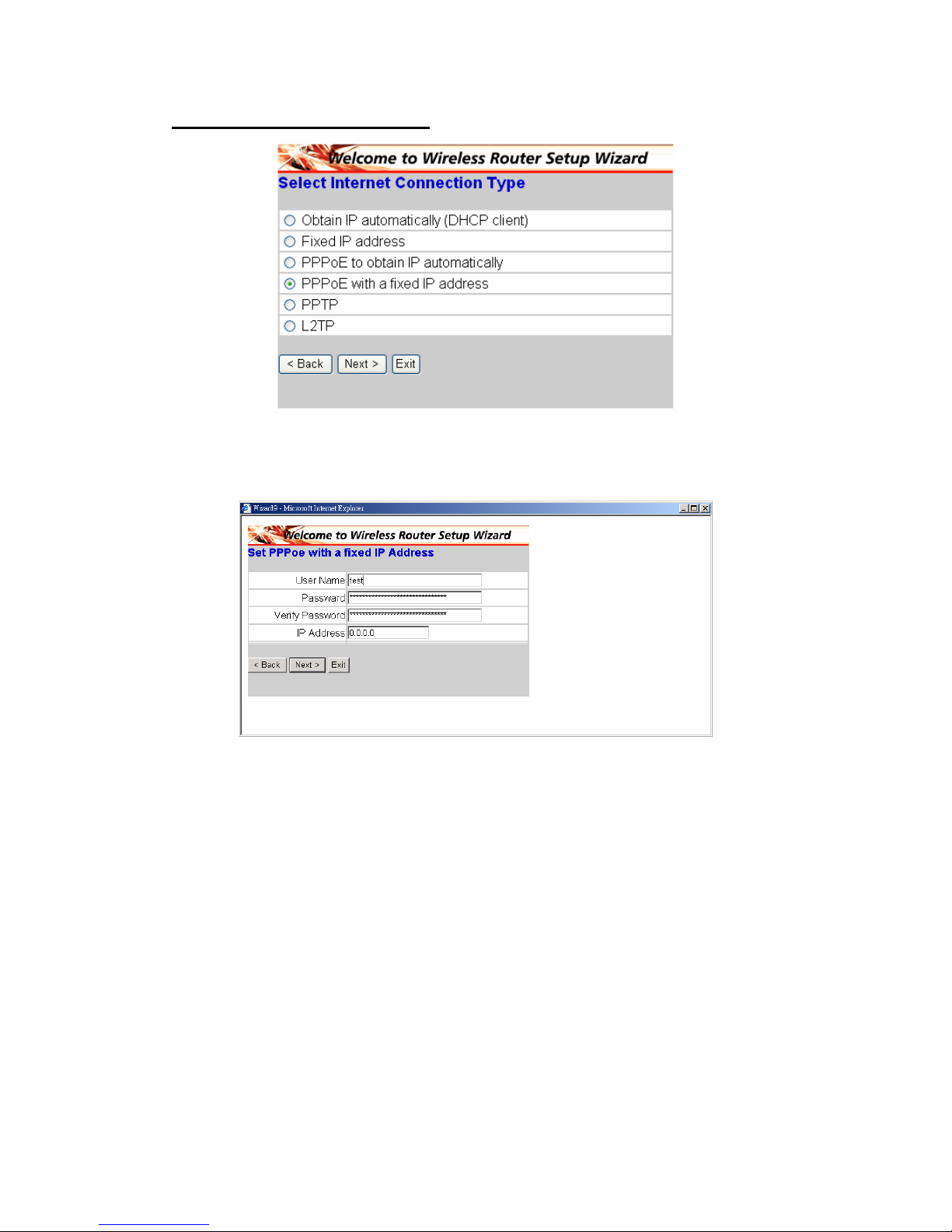
PPPoE with a fixed IP address:
If connected to the Internet using a PPPoE (Dial-up xDSL) Modem, the ISP will
provide a Password, User Name and a Fixed IP Address, choose this option
and enter the required information.
Page 13
10
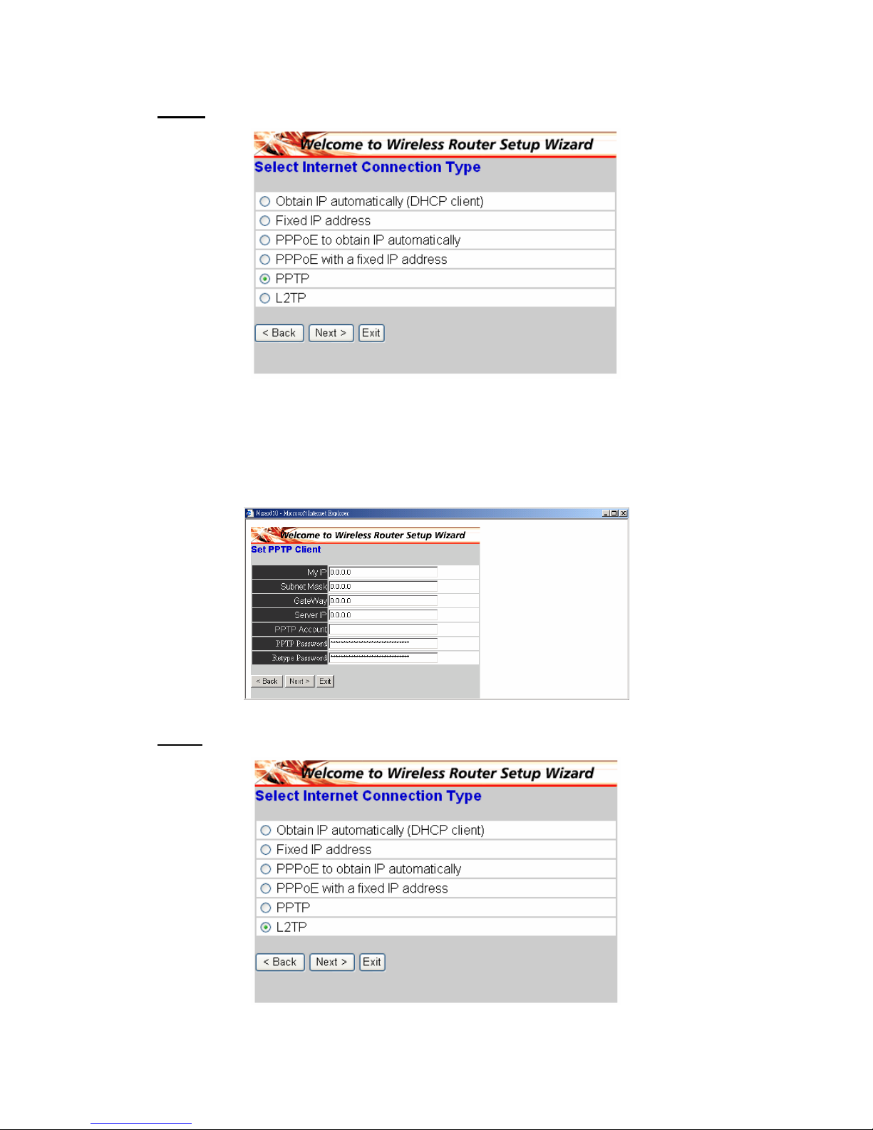
PPTP:
If connected to the Internet using a (PPTP) xDSL Modem, enter the your IP
Address, Subnet Mask, Gateway, Server IP, PPTP Account and PPTP
Password, Your Subnet Mask required by your ISP in the appropriate fields. If
your ISP has provided you with a Connection ID, enter it in the Connection ID
field, otherwise, leave it zero.
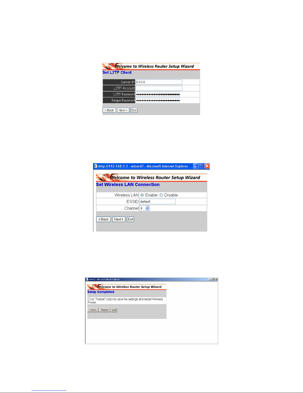
L2TP:
Page 14
11
If connected to the Internet using a L2TP (Dial-up xDSL) Modem, the ISP will
provide a Server IP. Account and Password. Choose this option and enter the
required information.
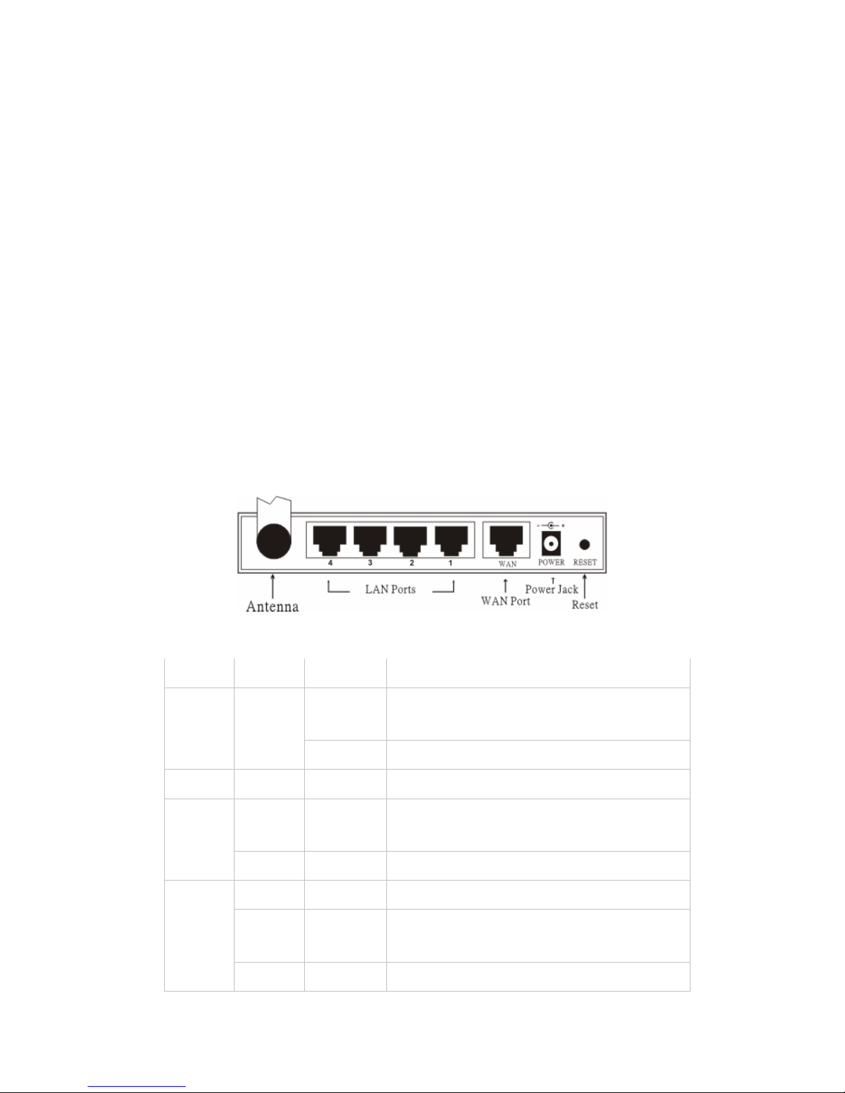
◆ Step 5: Set Wireless LAN connection
Click “enable” to enable wireless LAN. If you enable the wireless LAN, type the
SSID in the text box and select a communications channel. The SSID and
channel must be the same as wireless devices attempting communication to
the router.
◆ Step 6: Restart
The Setup wizard is now completed. The new settings will be effective after the
Wireless router restarted. Please click “Restart” to reboot the router. If you
do not want to make any changes, please click “Exit” to quit without any
changes. You also can go back to modify the setting by clicking “Back”.
Page 15
12
§ Verbinden des drahtlosen Breitband-Routers mit dem
Netzwerk
1. Verbinden Sie das Netzteil mit dem Anschluss an der Rückseite. Verbinden
Sie das Netzteil mit einer Steckdose. Normalerweise leuchtet die
Power-LED daraufhin auf.
2. Schalten Sie Ihr Kabel-/DSL-Modem aus. Verbinden Sie den
Ethernet-Anschluss an dem Kabel-/DSL-Modem über ein Ethernet-Kabel
mit dem WAN-Anschluss an der Rückseite des Routers. Schalten Sie bitte
nach dieser Verbindung Ihr Kabel-/DSL-Modem ein. Normalerweise
leuchtet die WAN PORT-LCD daraufhin auf.
3. Verbinden Sie den LAN-Anschluss an der Rückseite des Routers über ein
Ethernet-Kabel mit einem freien Ethernet-Anschluss an dem
Netzwerk-Adapter in dem Computer, der für die Router-Konfiguration
verwendet wird. Normalerweise leuchtet die LED des LAN-Anschluss 1
daraufhin auf.
4. Starten Sie Ihren Computer neu.
5. Verbinden Sie Ihre Computer, die über Ethernet-Funktionen verfügen, über
Ethernet-Kabel mit den restlichen Ethernet LAN-Anschlüssen an der
Rückseite des Routers.
◆ Rückansicht:
◆ LED-Anzeigen:
LED Farbe Status Beschreibung
Ein
Die Stromversorgung ist richtig
verbunden.
Power
Grün
Aus Das Gerät ist nicht mit Strom versorgt.
Status
Grün Ein Das Gerät ist mit dem WLAN verbunden.
Ein
Es besteht eine Verbindung mit dem
WAN-Anschluss
WAN
Blinkt Es werden Daten übertragen.
Ein Eine Verbindung besteht.
Ein Blinkt
Es werden Datenpakete gesendet oder
empfangen.
WLAN
Aus — Es besteht keine Verbindung.
Page 16
13
Ein Eine Verbindung besteht
Ein Blinkt Es werden Daten übertragen. LAN
Aus — Es besteht keine LAN-Verbindung.
§ Schnelle Einstellung über den Assistenten
◆ Ihren Webbrowser öffnen
Sie können zu jeder Zeit das Konfigurationsmenü öffnen, indem Sie einen
Webbrowser und dann die IP-Adresse dieses drahtlosen Routers eingeben.
Die Standard-IP ist 192.168.1.1.
Das Fenster wie unten abgebildet wird geöffnet. Bitte geben Sie den
Benutzernamen und das Kennwort ein. Die Werkeinstellung ist jeweils
"admin".
Das Hauptmenü wird daraufhin geöffnet.
Page 17
14
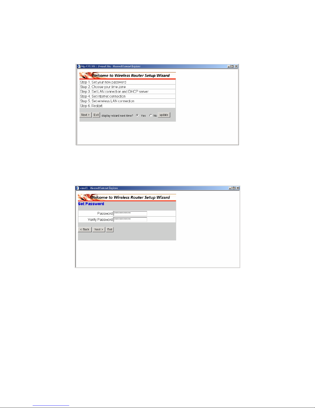
Sie können die Konfiguration Ihres drahtlosen Routers in 6 einfachen Schritten
fertig stellen, wenn Sie Schritt für Schritt den Anweisungen folgen. Bitte klicken
Sie zum Fortfahren auf “Next” auf dem Setup Wizard-Dialogfenster.
◆ Schritt 1: Ihr neues Kennwort einstellen
Sie können das Kennwort beliebig ändern und dann auf "Next" klicken, um
fortzufahren.
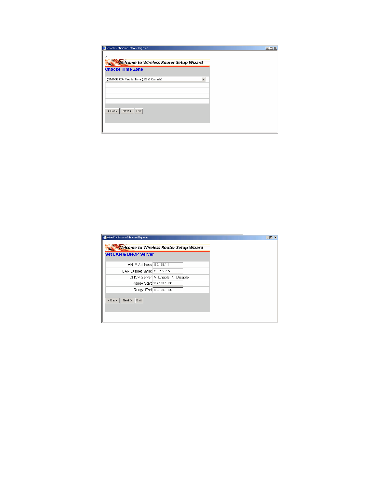
◆ Schritt 2: Ihre Zeitzone auswählen
Wählen Sie Ihre Zeitzone aus der Drop-down-Liste aus. Bitte klicken Sie zum
Fortfahren auf “Next”.
Page 18
15
◆ Schritt 3: Die LAN-Verbindung und den DHCP-Server
einstellen
Stellen Sie Ihre IP-Adresse und Subnetzmaske ein. Die Standard-IP ist
192.168.1.1. Bitte klicken Sie auf "Enabled", wenn Sie DHCP aktivieren
möchten. DHCP, wenn aktiviert, kann automatisch IP-Adressen zuweisen.
Bitte geben Sie über die Felder "Range start" und "Range end" den Bereich
der IP-Adressen an. Bitte klicken Sie zum Fortfahren auf [Next].
Page 19
16
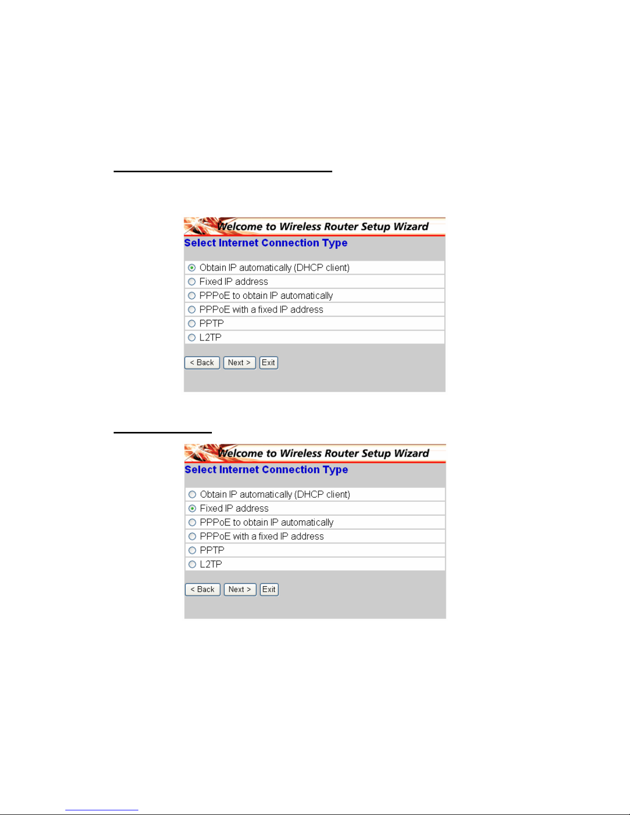
◆ Schritt 4: Internetverbindung einstellen
Wählen Sie, wie der Router die Internetverbindung herstellen sollte: IP
automatisch beziehen, Feste IP-Adresse, PPPoE und IP-Adresse automatisch
beziehen, PPPoE mit einer festen IP-Adresse und PPTP.
IP automatisch beziehen (DHCP-Client):
Haben Sie den DHCP-Server aktiviert, dann wählen Sie bitte "IP automatically
(DHCP client)", damit der Router automatisch IP-Adressen zuweist.
Feste IP-Adresse:
Page 20
17
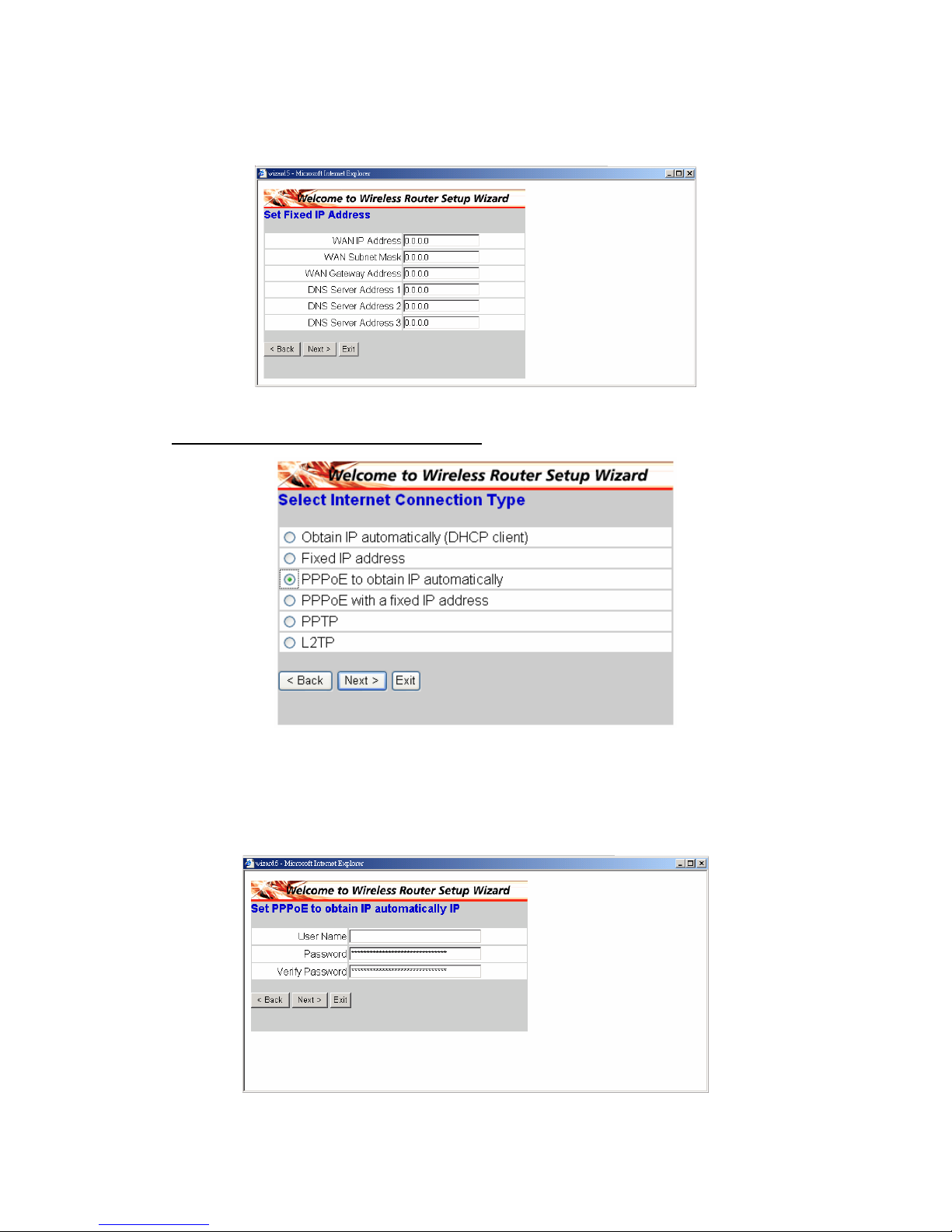
Wenn "Fixed IP address" gewählt wird, dann wird das folgende Fenster
geöffnet. Bitte stellen Sie die WAN-Adresse und den DNS-Server ein.
PPPoE und IP automatisch beziehen:
Wenn die Internetverbindung über ein PPoE (Dial-up xDSL)-Modem hergestellt
wird, dann gibt der Internetdienstanbieter ein Kennwort und einen
Benutzernamen an. Der Internetdienstanbieter verwendet PPPoE. Wählen Sie
diese Option und geben die angeforderten Daten ein.
Page 21
18
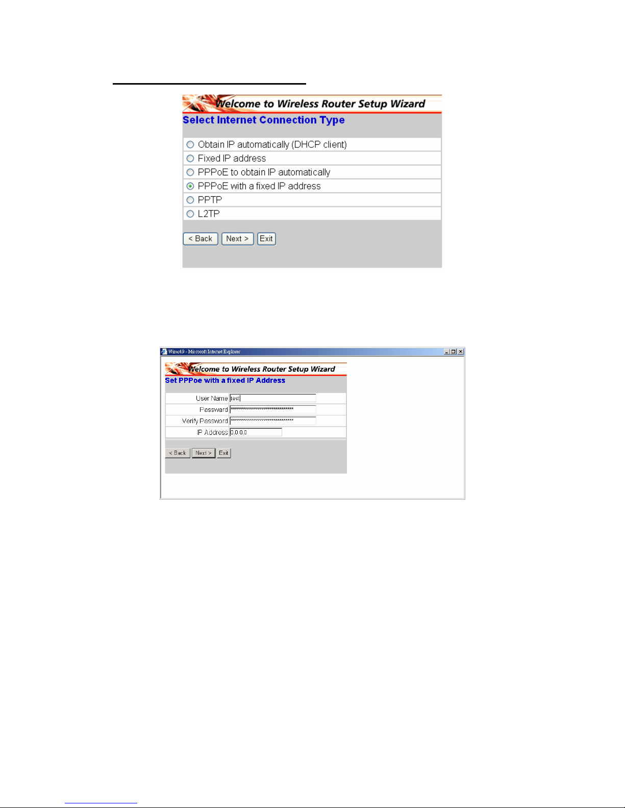
PPPoE mit einer festen IP-Adresse:
Wenn die Internetverbindung über ein PPoE (Dial-up xDSL)-Modem hergestellt
wird und der Internetdienstanbieter ein Kennwort, einen Benutzernamen und
eine feste IP-Adresse angibt, dann wählen Sie bitte diese Option und geben die
angeforderten Daten ein.
Page 22
19
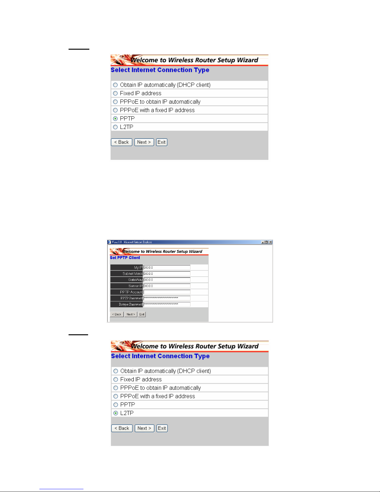
PPTP:
Wenn die Internetverbindung über ein (PPTP) xDSL-Modem hergestellt wird,
dann geben Sie bitte die von Ihrem Internetdienstanbieter angeforderten Daten
wie z.B. Ihre IP-Adresse, Subnetz-Maske, den Gateway, die Server-IP, den
PPTP-Benutzernamen und das PPTP-Kennwort in die entsprechenden Felder
ein. Hat Ihnen Ihr Internetdienstanbieter eine Verbindungs-ID gegeben, dann
geben Sie sie bitte in das "Connection ID"-Feld ein. Andernfalls lassen Sie bitte
das Feld leer.
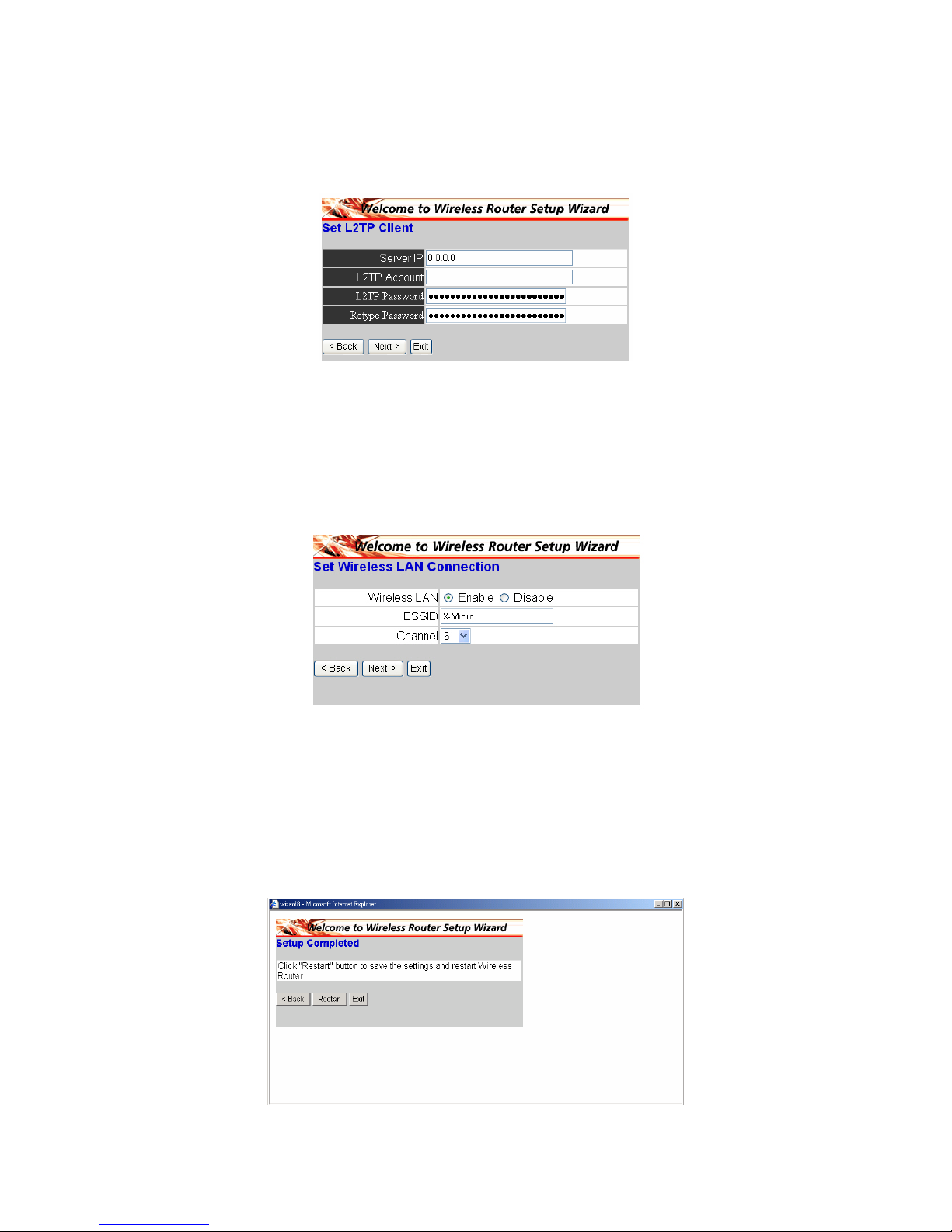
L2TP:
Page 23
20
Wenn die Internetverbindung über ein L2TP (Dial-up xDSL)-Modem hergestellt
wird, dann gibt der Internetdienstanbieter eine Server-IP an. Wählen Sie diese
Option und geben die angeforderten Daten ein.
◆ Schritt 5: Drahtlose LAN-Verbindung einstellen
Klicken Sie auf "Enable", um das drahtlose LAN zu aktivieren. Wenn Sie das
drahtlose LAN aktivieren, geben Sie bitte die SSID in das Textfeld ein und
wählen einen Kommunikationskanal aus. Die SSID und der Kanal muss mit
denen der drahtlosen Geräte, die mit dem Router kommunizieren möchten,
übereinstimmen.
◆ Schritt 6: Neu starten
Jetzt haben Sie den Vorgang mit dem Setup Wizard abgeschlossen. Die neuen
Einstellungen werden wirksam, nachdem der drahtlose Router neu gestartet
wird. Bitte klicken Sie auf "Restart", um den Router neu zu starten. Möchten
Sie keine Änderungen übernehmen, dann klicken Sie bitte auf "Exit", um den
Vorgang zu beenden, ohne Änderungen zu speichern. Sie können auch auf
"Back" klicken, um die Einstellungen erneut zu ändern.
Page 24
21
Connecter les routeurs haut débit sans fil à votre réseau
1. Connectez l'adaptateur d'alimentation au réceptacle sur le panneau arrière.
Branchez l'adaptateur d'alimentation sur le secteur. La LED d'alimentation
s'allume pour indiquer le bon fonctionnement.
2. Éteignez votre mode câble / DSL. A l'aide d'un câble Ethernet, reliez la
prise Ethernet située sur le modem câble / DSL et le port WAN sur le
panneau arrière de ce routeur. Après ce branchement, veuillez allumer
votre mode câble / DSL. Le PORT WAN s'allume pour indiquer le bon
fonctionnement
3. Insérez le câble Ethernet sur le port LAN du panneau arrière du routeur et
sur un port Ethernet disponible de l'adaptateur réseau de l'ordinateur qui
sera utilisé pour configurer le routeur. Le témoin LED du port LAN 1
s'allume pour indiquer le bon fonctionnement
4. Redémarrez alors votre ordinateur.
5. Branchez vos ordinateurs équipés Ethernet sur les ports LAN Ethernet
restants du panneau arrière de ce routeur, avec des câbles Ethernet
supplémentaires.
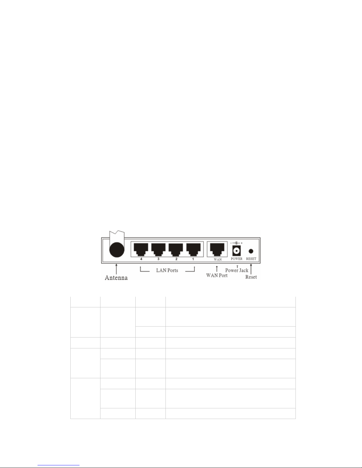
◆ Vue arrière:
◆ Témoins LED :
LED Couleur État Description
Marche
Indique le bon branchement à
l'alimentation électrique.
Alimen
tation
Vert
ÉTEINT L'appareil ne reçoit aucune alimentation
État Vert Marche Indique que l'appareil est relié au WLAN.
Marche Indique une connexion au port WAN
WAN
Clignot
ant
Transmission de données
Marche Le lien est établi
Marche
Clignot
ant
Transmission de paquets ou activité de
réception
WLAN
Éteint — Aucune activité de lien
Page 25
22
Marche Indique que la connexion est établie.
Marche
Clignot
ant
Transmission de données
LAN
ÉTEINT — Aucune connexion LAN
§ Configuration rapide via l'Assistant
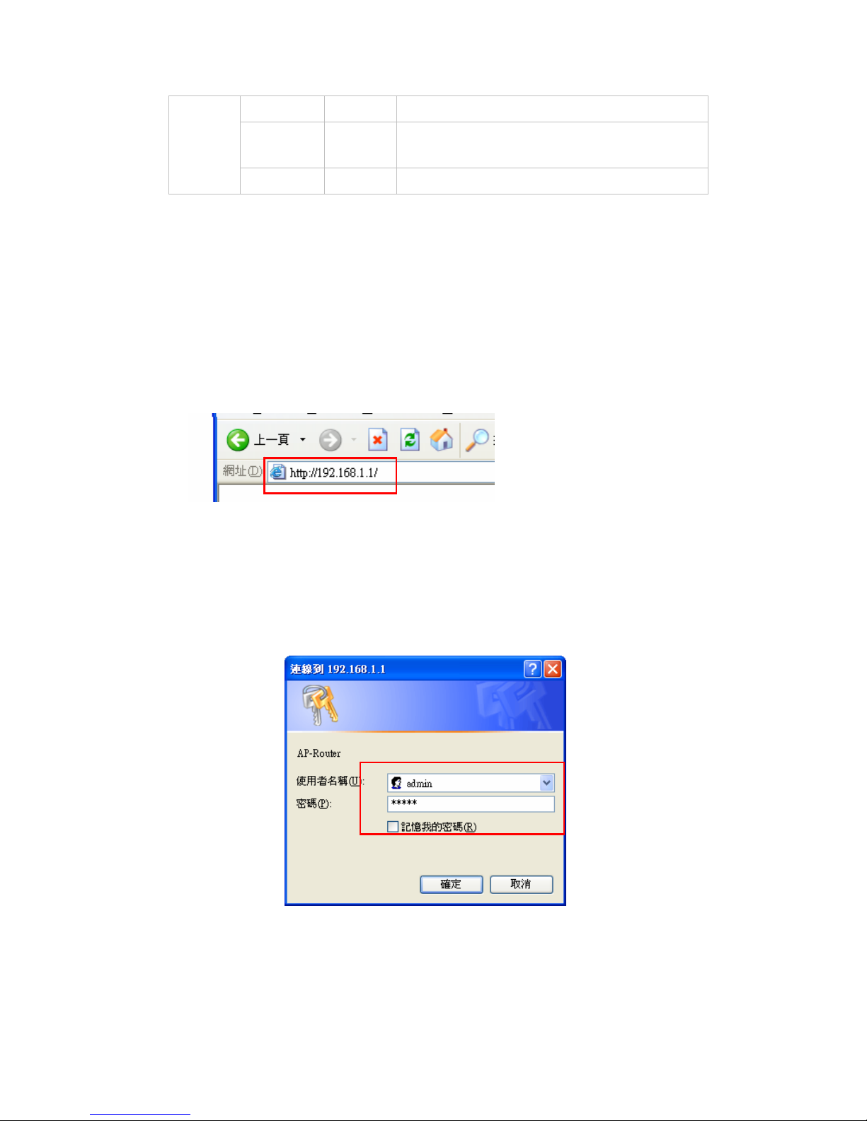
◆ Ouvrez votre navigateur Web
Vou pouvez démarrer l'accès au menu de configuration à tout moment en
ouvrant une fenêtre du navigateur Web et en tapant l'adresse IP de ce routeur
sans fil. L'adresse IP par défaut est 192.168.1.1.
La fenêtre ci-dessous apparaît. Veuillez saisir le nom d'utilisateur et le mot
de passe. Par défaut, les deux sont "admin".
L'écran du menu principal apparaît à présent.
Page 26
23
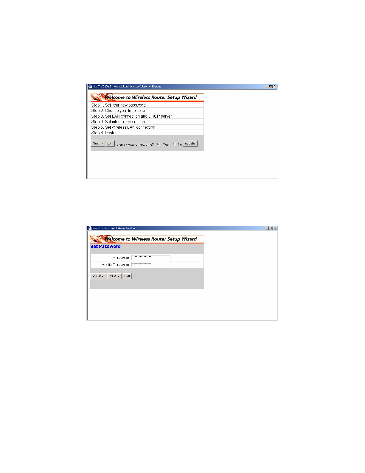
Vous pouvez simplement suivre la procédure pas à pas pour effectuer la
configuration de
votre routeur sans fil en 6 étapes simples. Veuillez cliquer sur “Next” sur
l'écran de l'assistant d'installation pour continuer.
◆ Étape 1: Définissez votre nouveau mot de passe
Vous pouvez modifier le mot de passe à votre guide puis cliquer sur “Next”
pour continuer.
Page 27
24
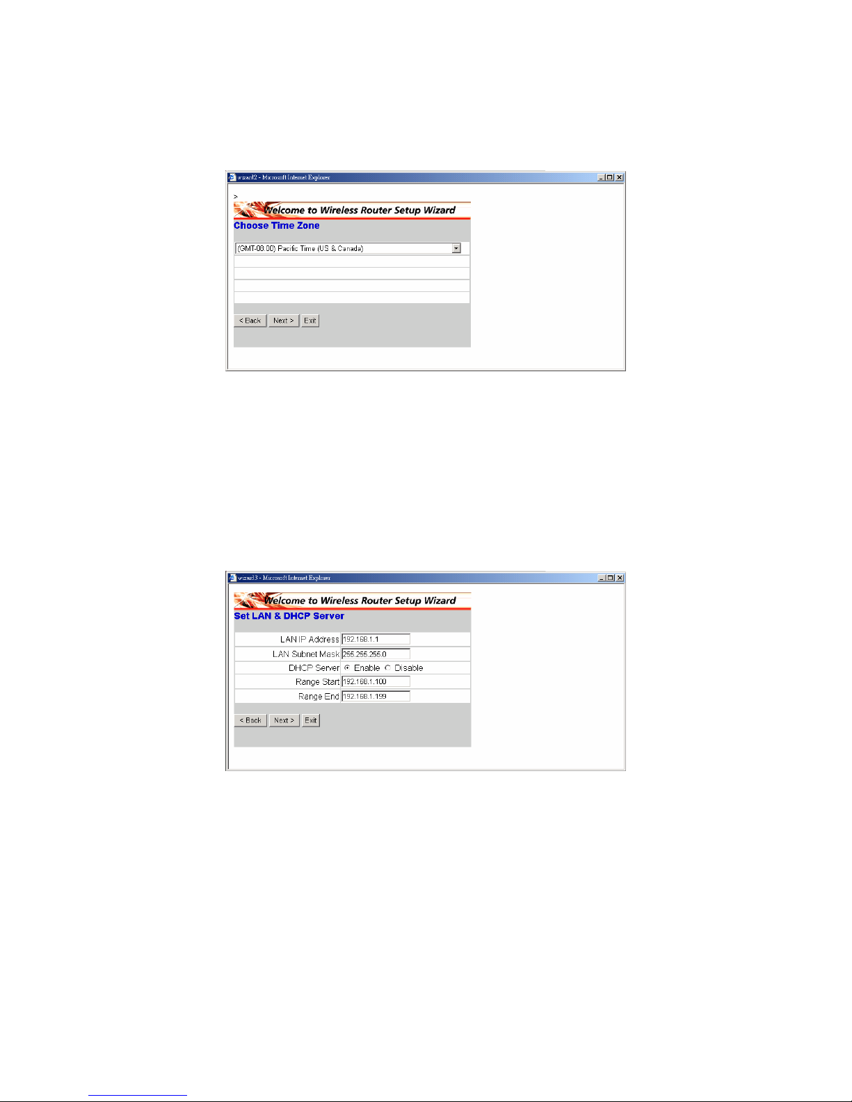
◆ Étape 2: Sélectionnez votre fuseau horaire
Sélectionnez votre fuseau horaire dans la liste déroulante. Veuillez cliquer
sur " Next " pour continuer.
◆ Étape 3: Définissez la connexion LAN et le serveur DHCP
Définissez votre adresse IP et le masque. L'adresse IP par défaut est
192.168.1.1. Si vous voulez activer DHCP, veuillez cliquer sur “Enabled”.
DHCP, si activé, est capable d'allouer automatiquement des adresses IP.
Veuillez allouer une plage d'adresses IP dans les champs “Range start” et
“Range end”. Veuillez cliquer sur "Suivant" pour continuer.
Page 28
25
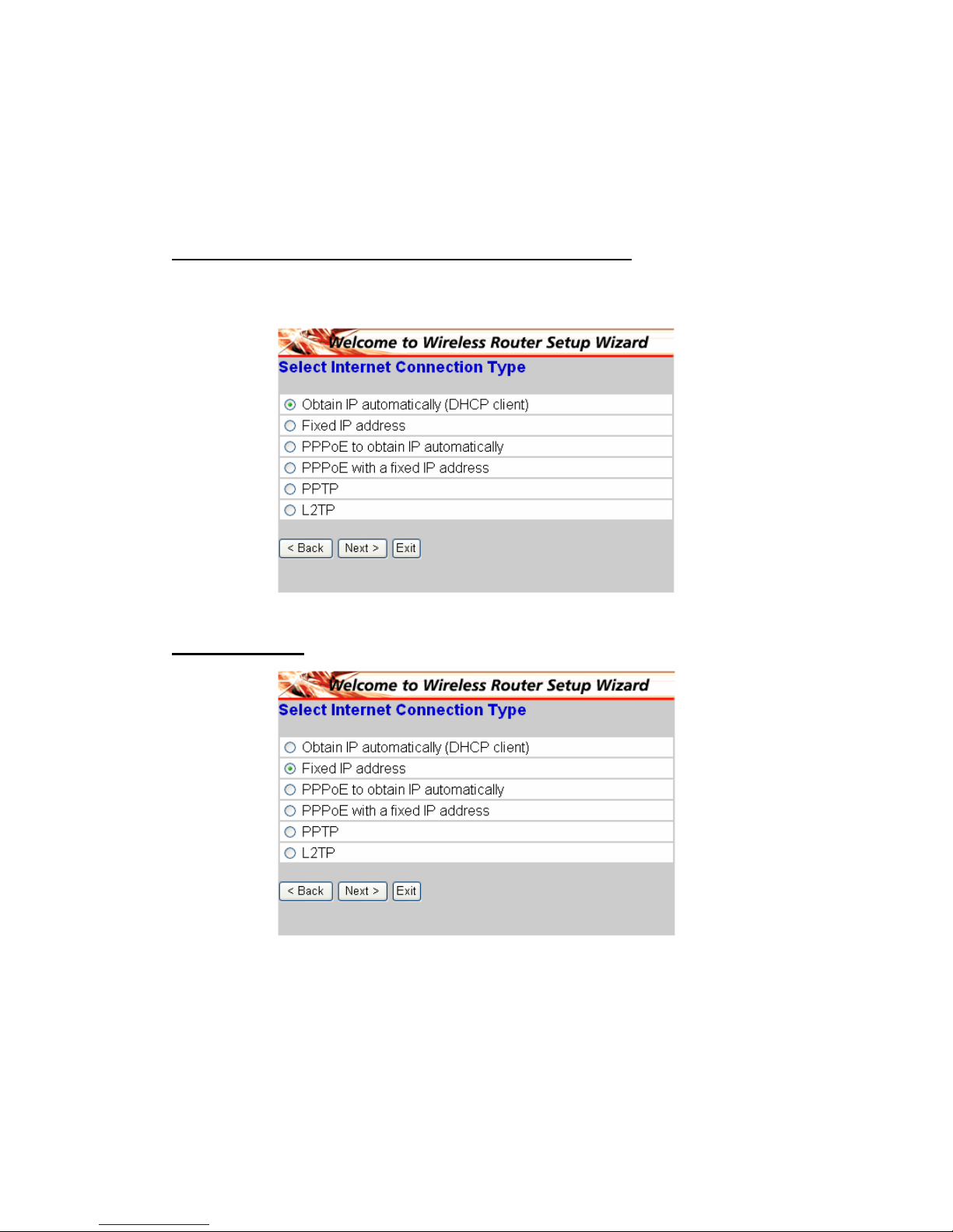
◆ Étape 4: Définir la connexion à Internet
Sélectionnez comment le routeur configure la connexion à Internet : Obtenir
une adresse IP automatiquement ; Adresse IP fixe ; PPPoE pour obtenir une
adresse IP automatiquement ; PPPoE avec une adresse IP fixe ; PPTP.
Obtenir une adresse IP automatiquement (client DHCP)
Si vous avez activé le serveur DHCP, choisissez "Obtain IP automatically
(DHCP client)" pour que le routeur alloue les adresses IP automatiquement.
Adresse IP fixe:
Page 29
26
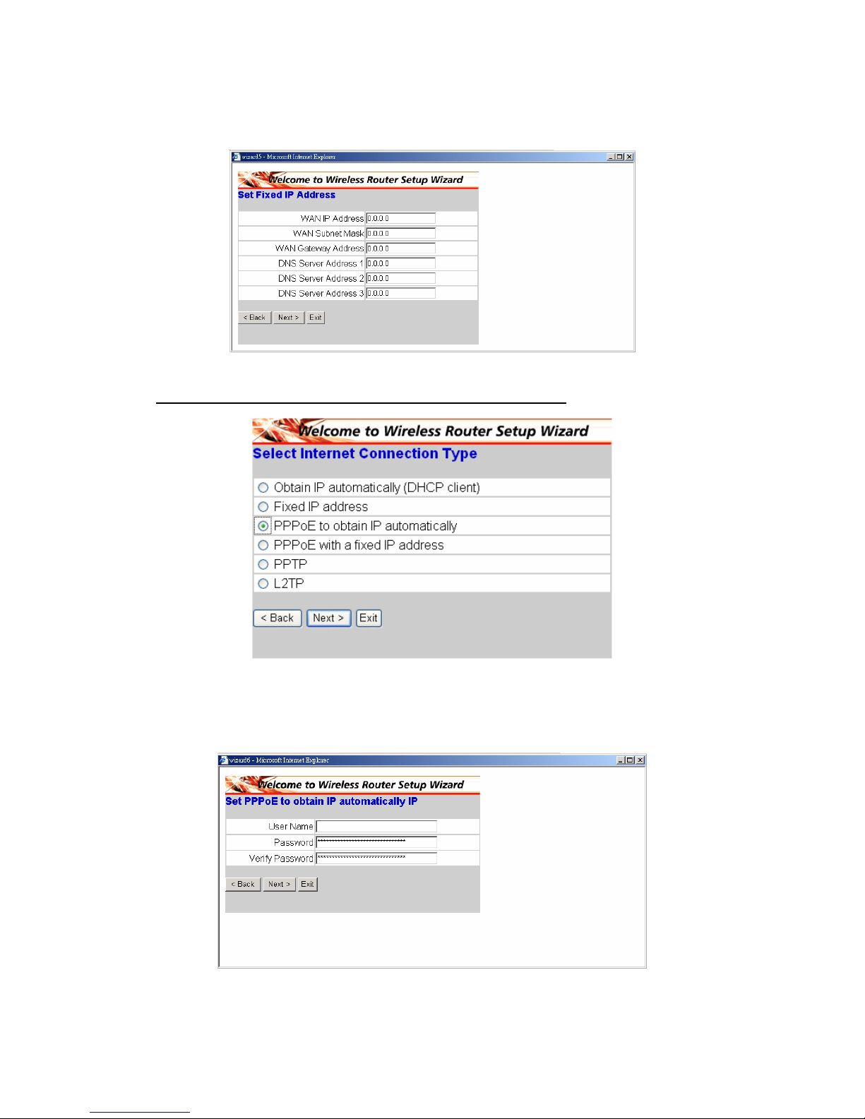
Si Fixed IP address est choisi, l'écran ci-dessous apparaît. Veuillez définir
l'adresse WAN et le serveur DNS.
PPPoE pour obtenir une adresse IP automatiquement:
Si connecté à Internet à l'aide d'un modem PPPoE (Dial-up xDSL), le FAI
fournit un mot de passe et un identifiant, puis le FAI utilise PPPoE. Choisissez
cette option et saisissez les informations requises.
Page 30
27
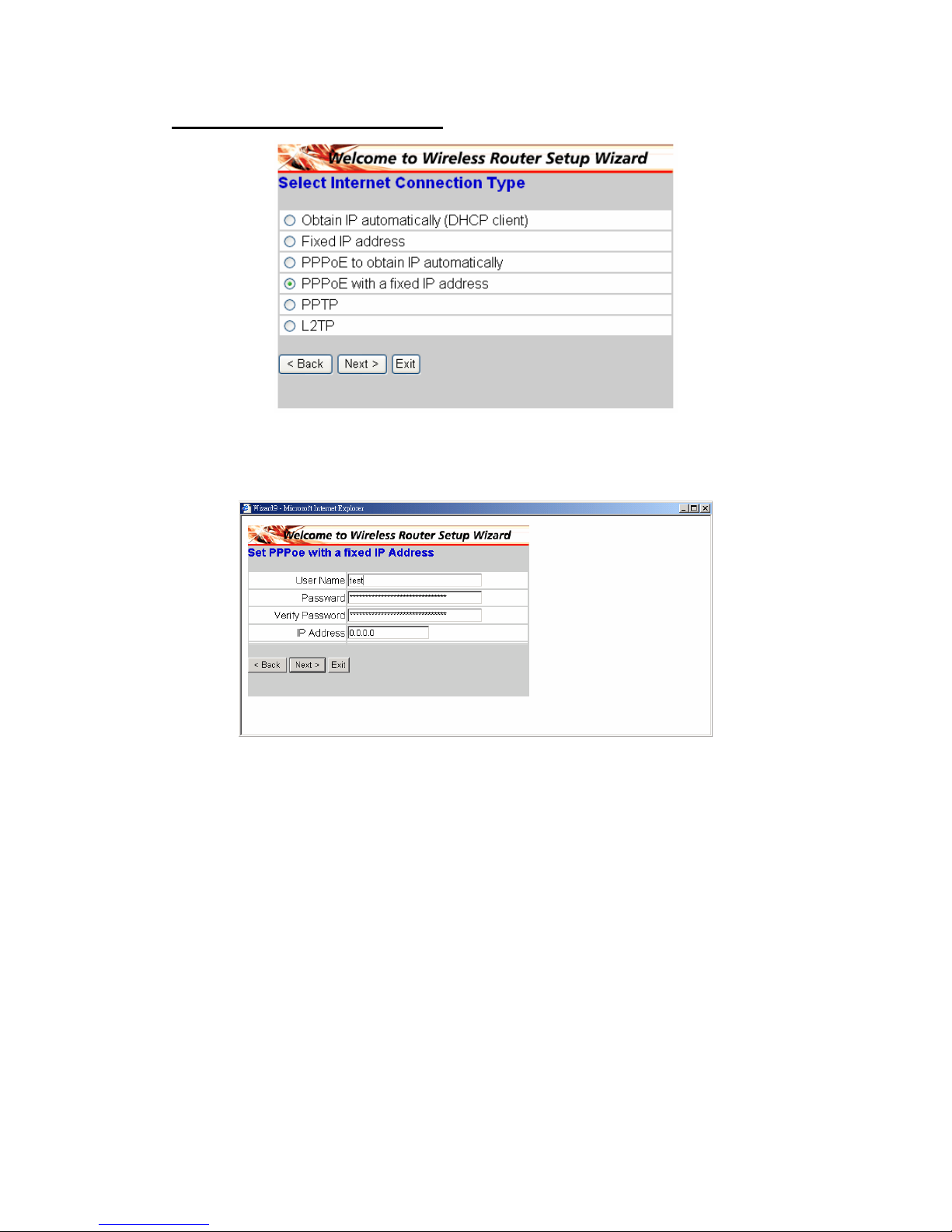
PPPoE avec une adresse IP fixe:
Si connecté à Internet à l'aide d'un modem PPPoE (numérotation xDSL), le
FAI fournit un mot de passe, un identifiant, et une adresse IP fixe. Choisissez
cette option et saisissez les informations requises.
Page 31
28
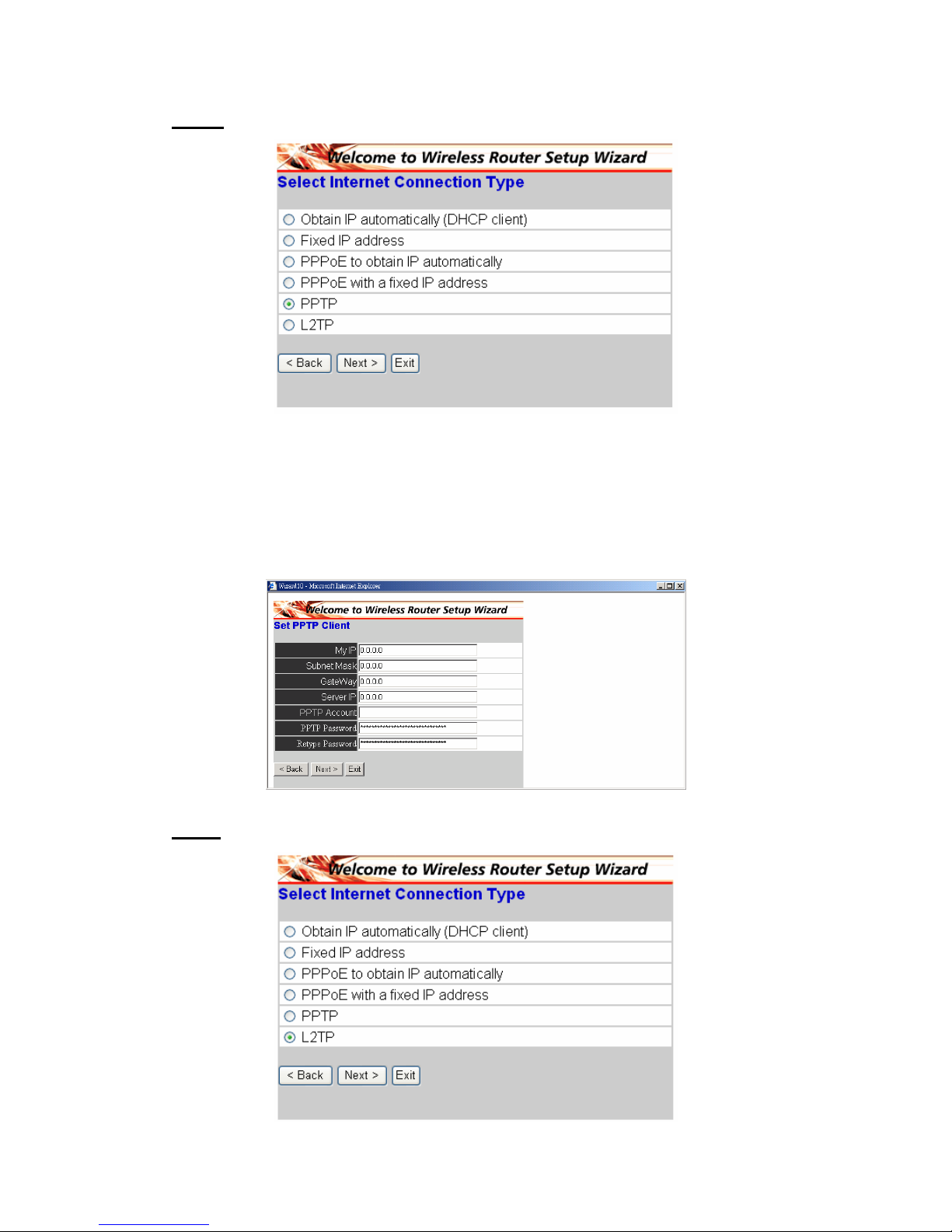
PPTP:
Si connecté à Internet à l'aide d'un modem (PPTP) xDSL, saisissez votre
addresse IP, le masque de sous réseau, la passerelle, le serveur IP, le compte
PPTP et le mot de passe PPTP, et votre masque de sous réseau requis par
votre FAI dans les champs appropriés. Si votre FAI vous a fourni un ID de
connexion, saisissez le dans le champs de Connection ID, sinon laissez le
vierge.
L2TP:
Page 32
29
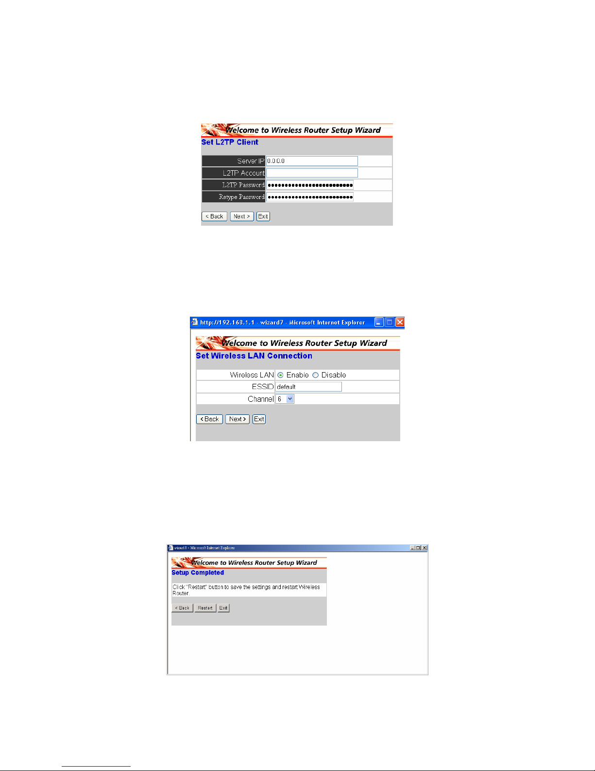
Si connecté à Internet à l'aide d'un modem L2TP (Dial-up xDSL), le FAI fournit
un compte serveur IP, et un mot de passe. Choisissez cette option et saisissez
les informations requises.
◆ Étape 5: Définir la connexion LAN sans fil
Cliquez sur “enable” pour activer le LAN sans fil. Si vous activez le LAN sans fil,
saisissez le SSID dans la boîte de texte et sélectionnez un canal de
communication. Le SSID et le canal doivent être identiques à ceux des
périphériques sans fil qui essayent de communiquer avec le routeur.
◆ Étape 6: Redémarrer
L'assistant d'installation est terminé à présent. Les nouveaux réglages sont
effectifs une fois le routeur sans fil redémarré. Veuillez cliquer sur “Restart”
pour redémarrer le routeur. Si vous ne voulez apporter aucune modification,
veuillez cliquer sur “Exit” pour quitter sans modification. Vous pouvez
également revenir pour modifier le réglage en cliquant sur “Back”.
Page 33
30
§ De draadloze breedbandrouter verbinden met uw
netwerk
1. Sluit de voedingsadapter aan op de aansluiting op het paneel achteraan.
Stop de voedingsadapter in het stopcontact. De voedings-LED zal
inschakelen om aan te geven dat het apparaat correct werkt.
2. Schakel uw kabel/DSL-modem uit. Gebruik een ethernetkabel om de
ethernetaansluiting op de kabel/DSL-modem en de WAN-poort op het
achterpaneel van deze router aan te sluiten. Schakel uw kabel/DSL-modem
in nadat u deze aansluiting hebt voltooid. De WAN-poort zal oplichten om
een juiste werking aan te geven.
3. Stop de ethernetkabel in de LAN-poort op het achterpaneel van de router en
een beschikbare ethernetpoort op de netwerkadapter in de computer die zal
worden gebruikt om de router te configureren. De LED-lamp van LAN-poort
1 zal oplichten om een goede verbinding aan te geven.
4. Start vervolgens uw computer opnieuw op.
5. Sluit uw computers die met ethernet zijn uitgerust aan op de resterende
ethernet-LAN-poorten op het achterpaneel van deze router met de extra
ethernetkabels.
◆ Achteraanzicht:
◆ LED-indicators:
LED Kleur Status Beschrijving
Aan
geeft een correcte aansluiting op de
voeding aan.
Voedin
g
Groen
UIT Het apparaat krijgt geen stroom
Status Groen Aan
Geeft aan dat het apparaat verbonden is
met het WLAN.
Aan
Geeft een verbinding met de WAN-poort
aan
WAN
Knippere
nd
Gegevensoverdracht.
Aan De verbinding is gemaakt
Aan
Knippere
nd
Pakketoverdracht of ontvangst van
activiteit
WLAN
Uit — Geen verbindingsactiviteit
Page 34
31
Aan Geeft aan dat de verbinding is gemaakt.
Aan
Knippere
nd
Gegevensoverdracht
LAN
Uit — Geen LAN-verbindingen
§ Snelle instelling via de wizard
◆ Uw webbrowser openen
U kunt op elk ogenblik toegang krijgen tot het configuratiemenu door een
webbrowservenster te openen en het IP-adres van deze draadloze router te
typen. Het standaard IP-adres is 192.168.1.1.
Het onderstaande venster wordt weergegeven. Voer de gebruikersnaam en
het wachtwoord in. Voor beide items is de standaardinstelling "admin".
Nu wordt het scherm met het hoofdmenu geopend.
Page 35
32
U kunt het stapsgewijze proces volgen om de configuratie van uw draadloze
router in 6 eenvoudige stappen gebruiksklaar te maken. Klik op "Next" in het
scherm van de Setup Wizard om door te gaan.
◆ Stap 1: uw nieuw wachtwoord instellen
U kunt het wachtwoord naar wens wijzigen en vervolgens op "Next" klikken om
door te gaan.
Page 36
33
◆ Stap 2: Kies uw tijdzone
Selecteer uw tijdzone in de vervolgkeuzelijst. Klik op "Next" om door te gaan.
◆ Stap 3: De LAN-verbinding en DHCP-server instellen
Stel uw IP-adres en masker in. Het standaard IP-adres is 192.168.1.1. Klik
op “Enabled” als u DHCP wilt inschakelen. Met een ingeschakelde DHCP
kunt u IP-adressen automatisch toewijzen. Wijs het bereik van IP-adressen
toe in de velden “Range start” en “Range end”. Klik op "Next" om door te
gaan.
Page 37
34
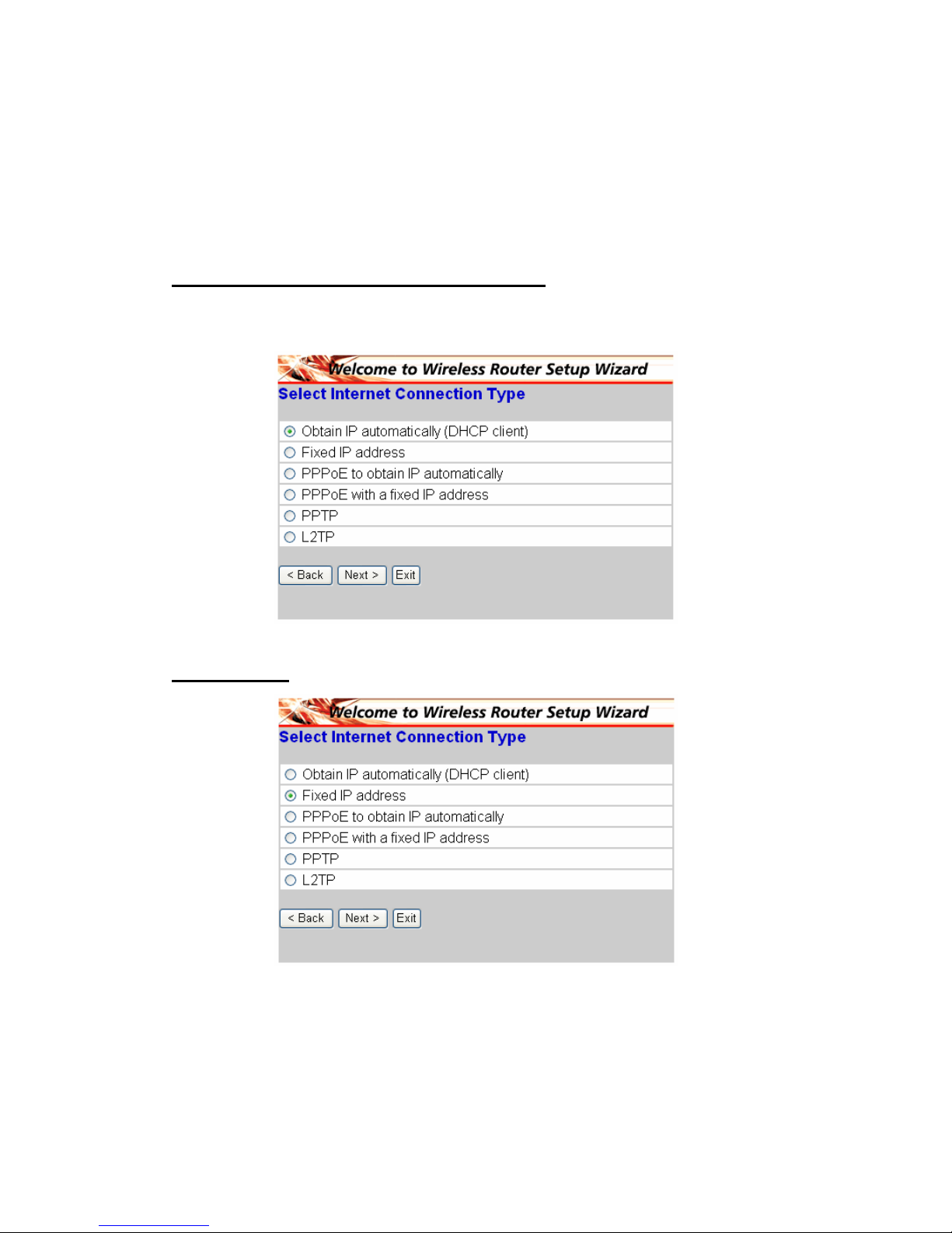
◆ Stap 4: De internetverbinding instellen
Selecteer de manier waarop de router de internetverbinding moet maken: IP
automatisch ophalen; Vast IP-adres; PPPoE om IP automatisch op te halen;
PPPoE met een vast IP-adres; PPTP.
IP-adres automatisch ophalen (DHCP-client):
Als u de DHCP-server hebt ingeschakeld, kiest u "Obtain IP automatically
(DHCP client)" zodat de router de IP-adressen automatisch kan toewijzen.
Vast IP-adres:
Page 38
35
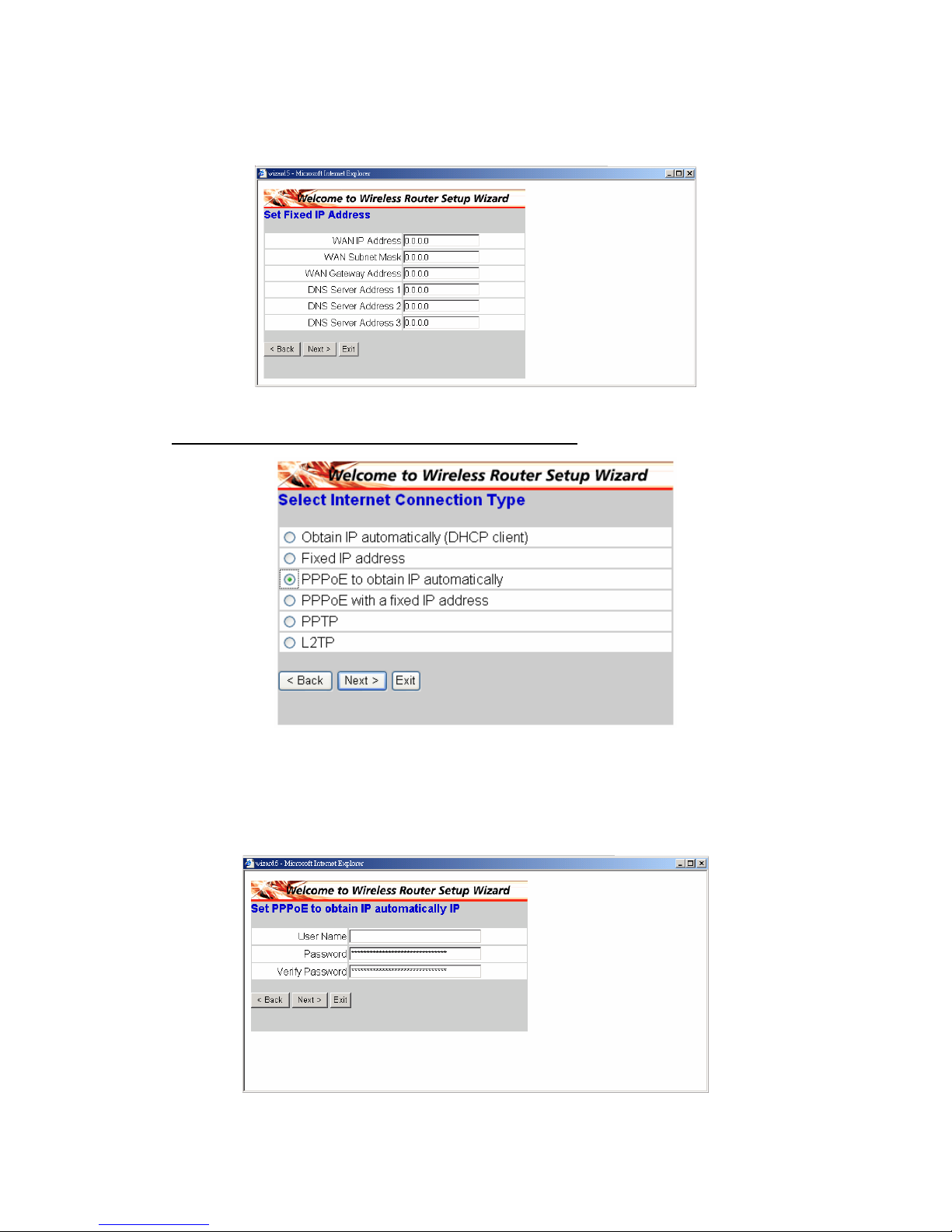
Als er een vast IP-adres is toegewezen, wordt het onderstaande scherm
weergegeven. Stel het WAN-adres en de DNS-server in.
PPPoE om het IP-adres automatisch op te halen:
Als u een verbinding hebt gemaakt met het internet via een PPPoE-modem
(xDSL-inbelmodem), zal de ISP een wachtwoord en een gebruikersnaam
bieden. Daarna zal de ISP PPPoE gebruiken. Kies deze optie en voer de
gewenste informatie in.
Page 39
36
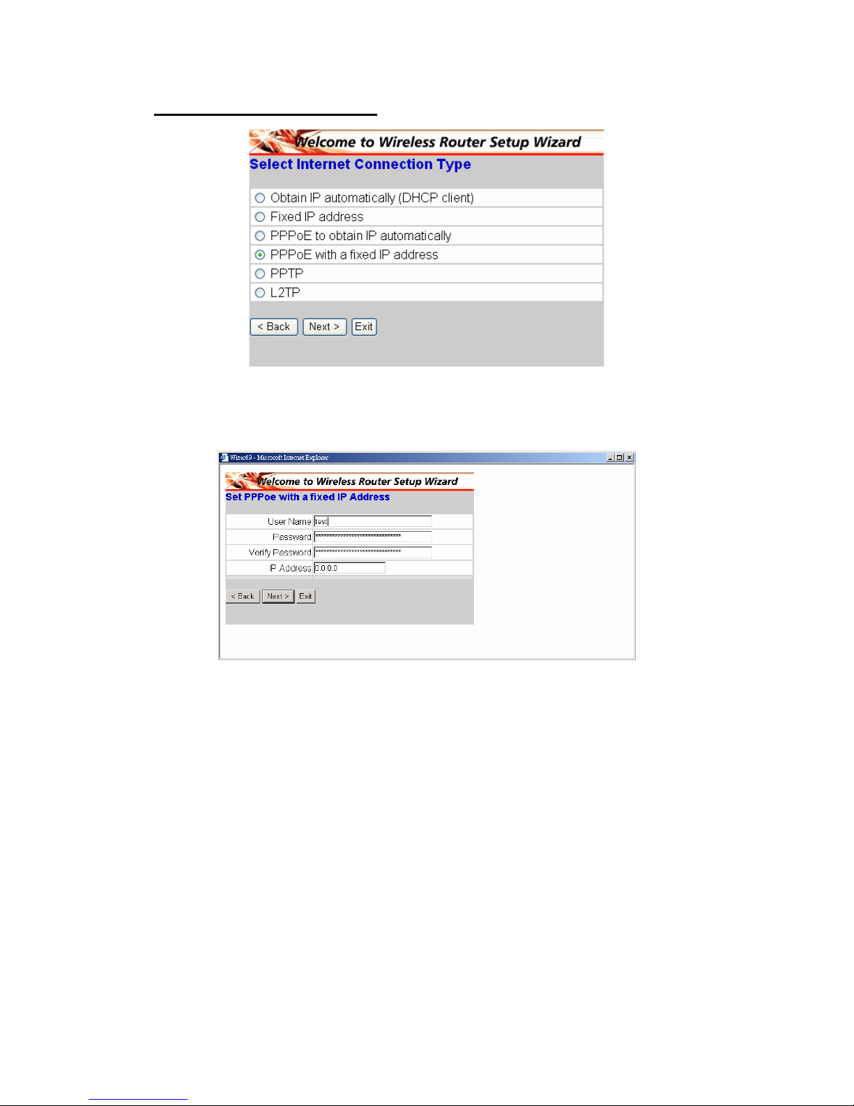
PPPoE met een vast IP-adres:
Als u een verbinding hebt gemaakt met het internet via een PPPoE-modem
(xDSL-inbelmodem), zal de ISP u een wachtwoord, gebruikersnaam en vast
IP-adres bieden. Kies deze optie en voer de gewenste informatie in.
Page 40
37
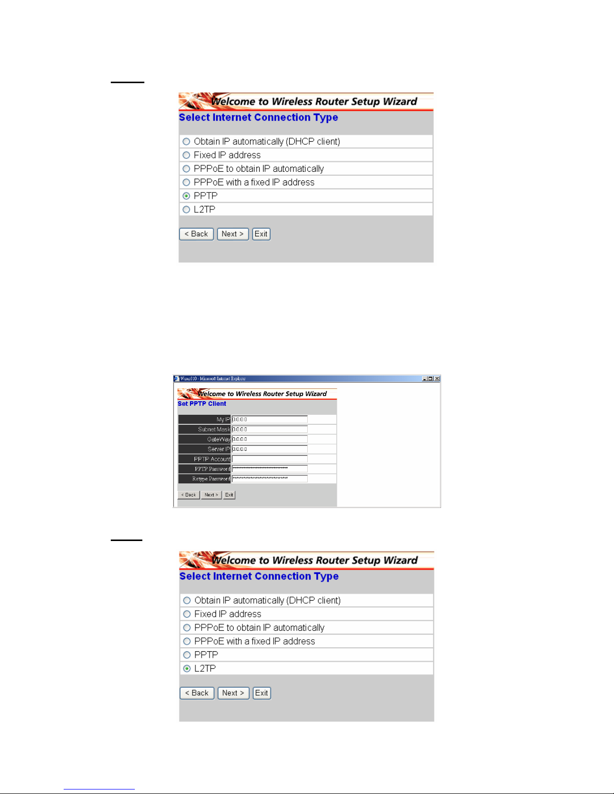
PPTP:
Als u een verbinding met het internet hebt gemaakt via een xDSL-modem
(PPTP), voert u het IP-adres, het subnetmasker, de gateway, het IP-adres van
de server, de PPTP-account, het PPTP-wachtwoord en uw subnetmasker die
door uw SIP zijn vereist, in de geschikte velden in. Als uw ISP u een
verbindings-ID hebt gegeven, voert u deze in het veld Connection ID in. Anders
laat u het veld leeg.
L2TP:
Page 41
38
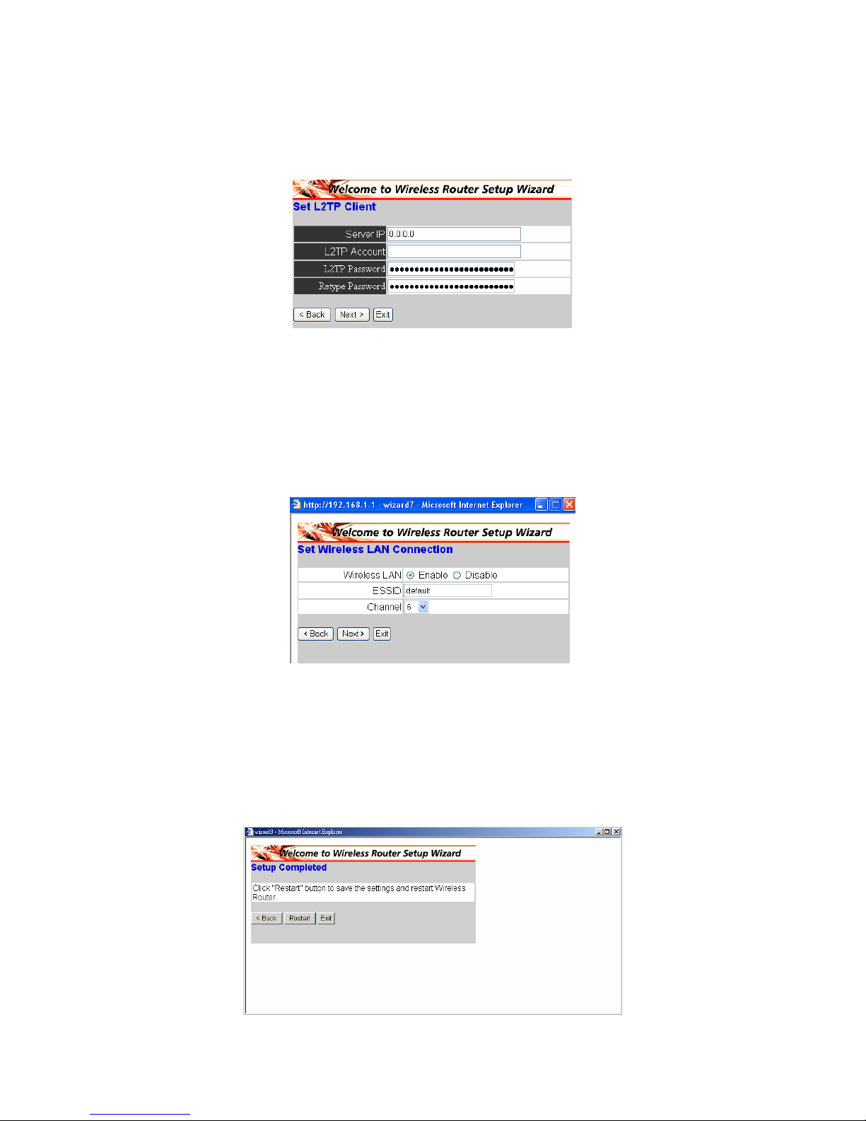
Als u een verbinding hebt gemaakt met het internet via een L2TP-modem
(xDSL-inbelmodem), zal de ISP u een server-IP-adres bieden. Account en
wachtwoord. Kies deze optie en voer de gewenste informatie in.
◆ Stap 5: De draadloze LAN-verbinding instellen
Klik op "enable" om het draadloos LAN in te schakelen. Als u het draadloos
LAN inschakelt, typt u de SSID in het tekstvak en selecteert u een
communicatiekanaal. De SSID en het kanaal moeten hetzelfde zijn als de
draadloze apparaten die proberen een communicatie tot stand te brengen met
de router.
◆ Stap 6: Opnieuw opstarten
De Setup-wizard is nu voltooid. De nieuwe instellingen zullen worden
toegepast nadat de draadloze router opnieuw is opgestart. Klik op “Restart”
om de router opnieuw op te starten. Als u geen wijzigingen wilt aanbrengen,
klikt u op "Exit" om af te sluiten zonder wijzigingen aan te brengen. Door op
"Back" te klikken, kunt u ook terugkeren om de instelling te wijzigen.
Page 42
39
§ Collegamento del router wireless a banda larga alla rete
1. Collegare l’adattatore di corrente al connettore sul pannello posteriore.
Collegare l’adattatore alla presa di corrente. Il LED d’alimentazione si
illuminerà ad indicare il corretto funzionamento.
2. Spegnere il modem Cavo/DSL. Usare un cavo Ethernet per collegare il
connettore Ethernet del modem Cavo/DSL e la porta WAN sul pannello
posteriore del router. Dopo avere seguito questo collegamento, accendere
il modem Cavo/DSL. Il LED della porta WAN si illuminerà ad indicare il
corretto funzionamento.
3. Usare un cavo Ethernet per collegare la porta LAN sul pannello posteriore
del router ad una porta Ethernet disponibile sulla scheda di rete del
computer che sarà usato per configurare il router. Il LED della porta LAN
numero 1 si illuminerà ad indicare il corretto funzionamento.
4. Quindi, riavviare il computer.
5. Collegare i computer attrezzati Ethernet alle porte LAN rimanenti sul
pannello posteriore del router usando gli altri cavi Ethernet.
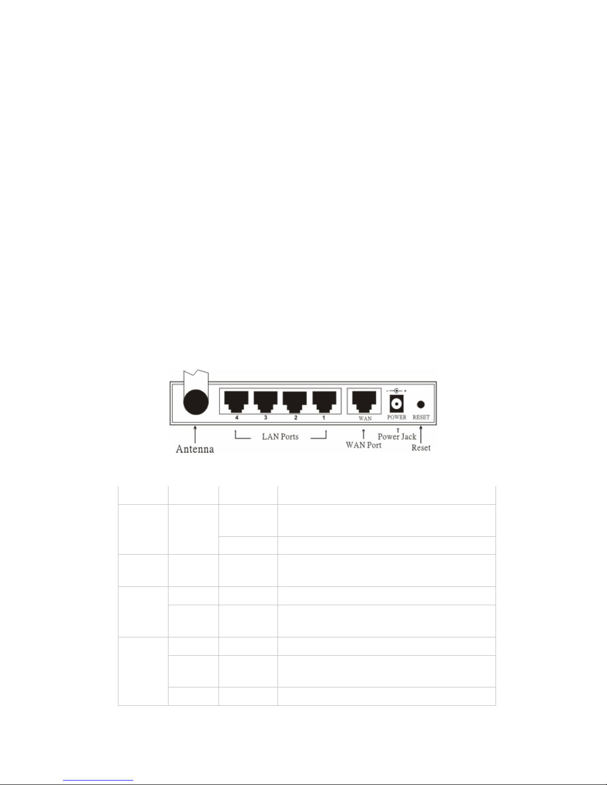
◆ Veduta posteriore:
◆ Indicatori LED:
LED Colore Stato Descrizione
Acceso
Indica l’appropriato collegamento
all’alimentazione
Alimen
tazione
Verde
Spento L'unità non riceve alimentazione
Stato Verde Acceso
Indica che il dispositivo è collegato alla
WLAN.
Acceso Indica il collegamento alla porta WAN
WAN
Lampegg
iante
Trasmissione dei dati.
Acceso Il collegamento è stabilito
Acceso
Lampegg
iante
Attività di trasmissione o ricezione dei
pacchetti
WLAN
Spento — Nessuna attività di collegamento
Page 43
40
Acceso Indica che la connessione è stabilita.
Acceso
Lampegg
iante
Trasmissione dei dati
LAN
Spento — Nessuna connessione LAN
§ Installazione rapida con procedura guidata
◆ Aprire il browser Web
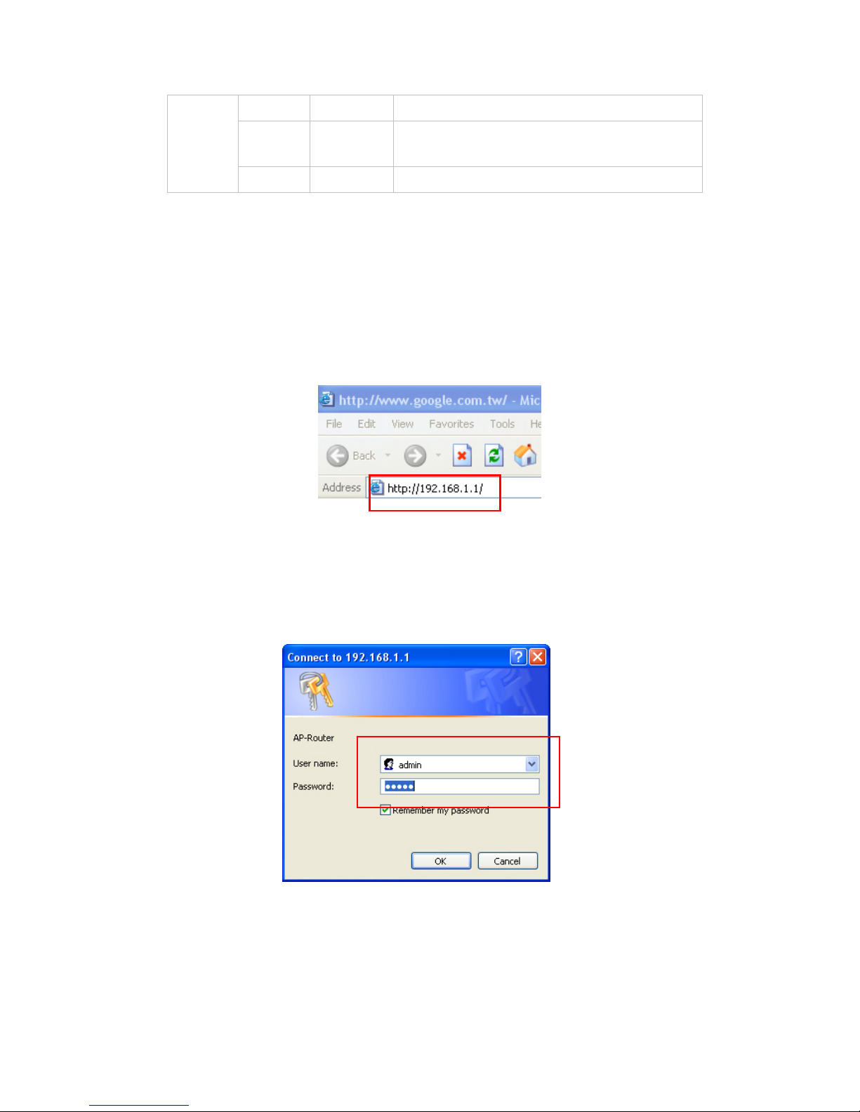
Si può avere accesso al menu di configurazione in qualsiasi momento aprendo
un browser Web e scrivendo l'indirizzo IP del router wireless. L'indirizzo IP
predefinito è 192.168.1.1.
Apparirà la finestra che segue. Inserire il nome utente e la password. Per
entrambi i campi, l’impostazione predefinita è "admin".
Adesso, sullo schermo appare il menu principale.
Page 44
41
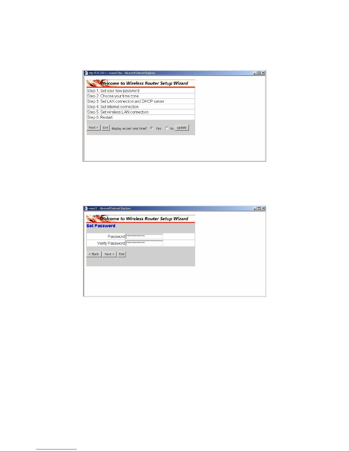
Seguire la procedura guidata per configurare il router wireless in 6 semplici
fasi. Nella schermata della procedura guidata, fare clic su "Next" per
continuare.
◆ Fase 1: Impostazione della nuova password
La password può essere cambiata come preferito; poi fare clic su “Next” per
continuare.
Page 45
42
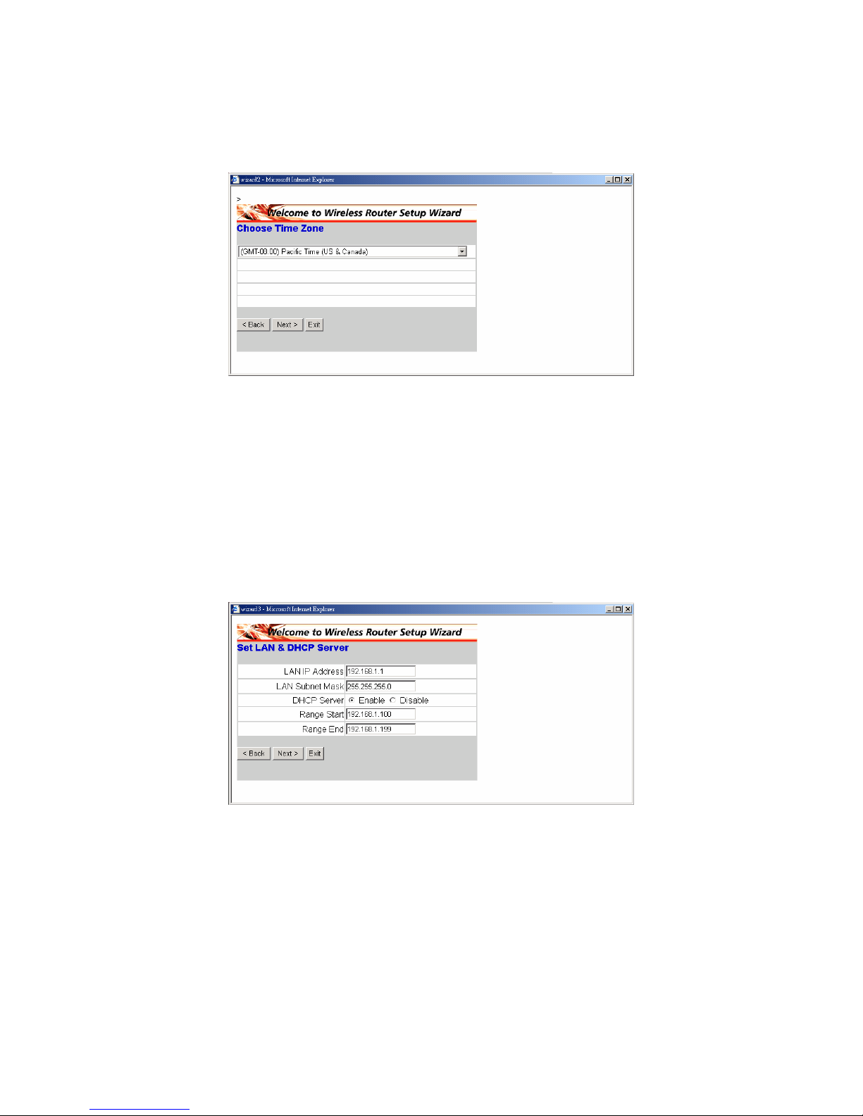
◆ Fase 2: Selezione del fuso orario
Selezionare il fuso orario dall'elenco a discesa. Fare clic su "Next" per
continuare.
◆ Fase 3: Impostazione della connessione LAN e del server
DHCP
Impostare l’indirizzo IP e la Subnet mask. L'indirizzo IP predefinito è
192.168.1.1.Se si vuole abilitare il server DHCP, fare clic su "Enabled".
Quando abilitato, il server DHCP è in grado si assegnare automaticamente gli
indirizzi IP. Assegnare l’intervallo degli indirizzi IP nei campi “Range start” e
“Range end”. Fare clic su "Next" per continuare.
Page 46
43
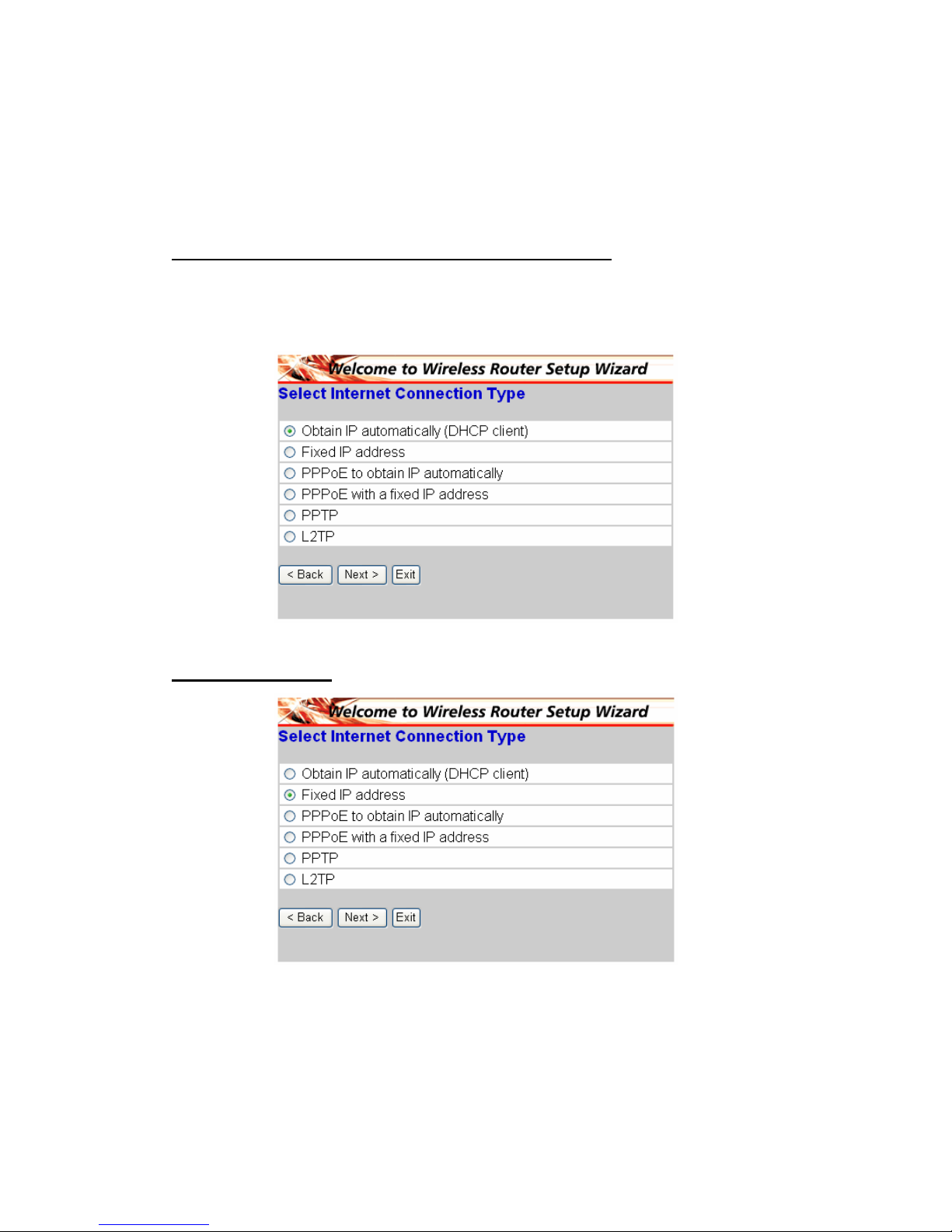
◆ Fase 4: Impostazione della connessione ad Internet
Selezionare come il router imposterà la connessione Internet: Ottieni
automaticamente indirizzo IP; Indirizzo IP statico; PPPoE per ottenere
automaticamente l’indirizzo IP; PPPoE con indirizzo IP statico; PPTP.
(Ottieni automaticamente indirizzo IP (Client DHCP)):
Se il server DHCP è abilitato scegliere " Ottieni automaticamente un indirizzo
IP (client DHCP)" per far sì che il router assegni automaticamente gli indirizzi
IP.
Indirizzo IP statico:
Page 47
44
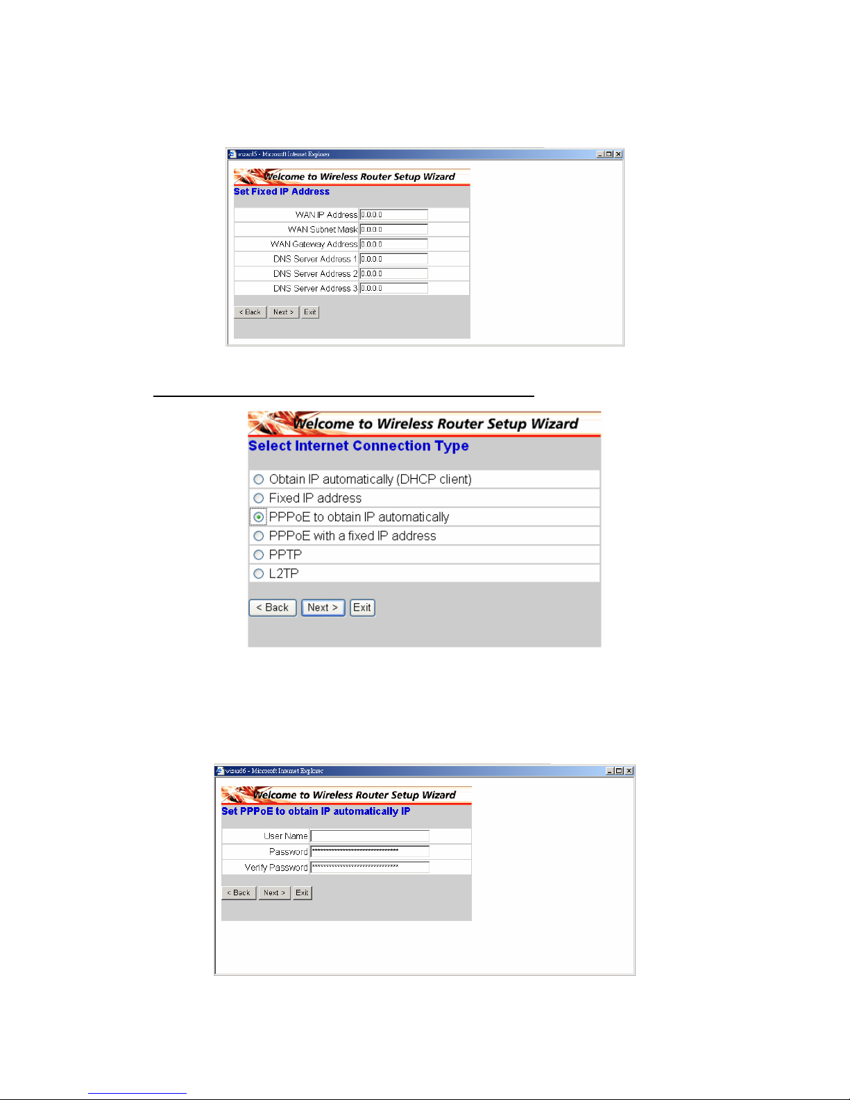
Se è assegnato l'indirizzo IP statico, apparirà la schermata mostrata di seguito.
Impostare l'indirizzo WAN ed il server DNS.
PPPoE per ottenere automaticamente l’indirizzo IP:
Se il collegamento ad Internet è eseguito usando un modem PPPoE
(connessione remota xDSL), il provider (ISP) fornirà una password ed un
nome utente, quindi il provider (ISP) usa il protocollo PPPoE. Scegliere questa
opzione ed inserire le informazioni necessarie.
Page 48
45
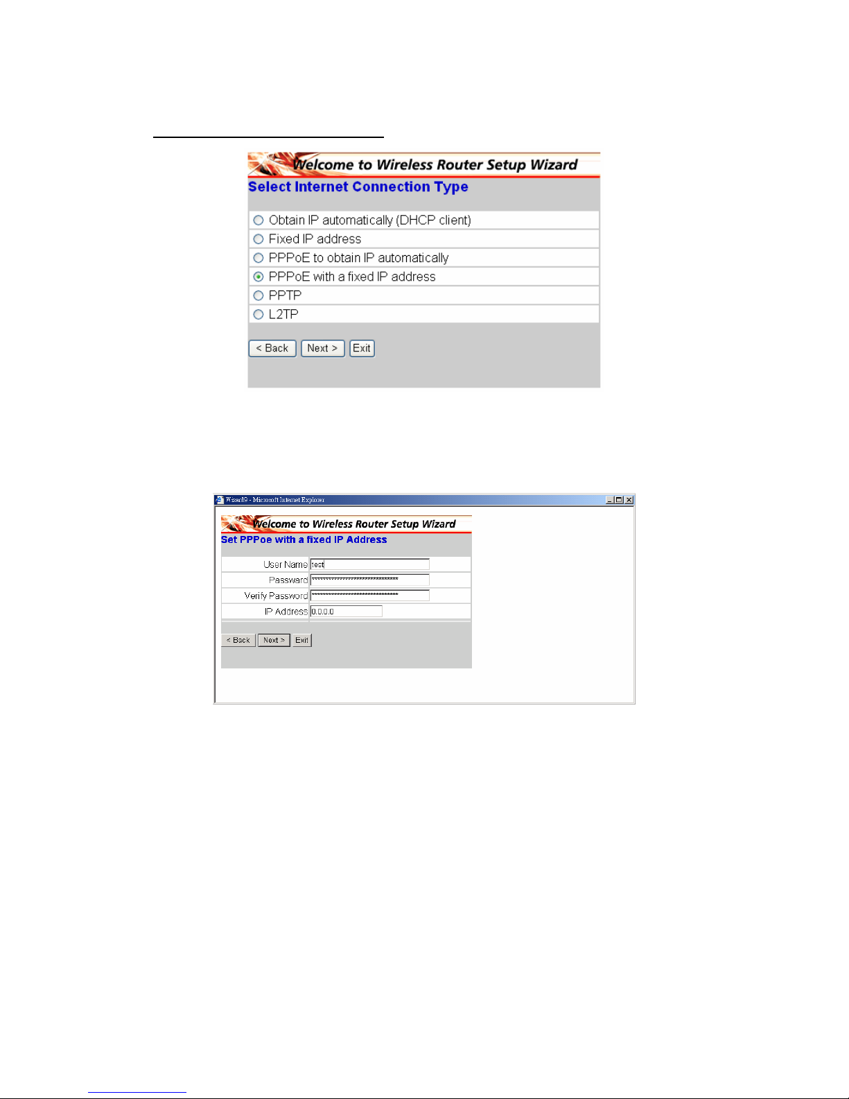
PPPoE con indirizzo IP statico:
Se il collegamento ad Internet è eseguito usando un modem PPPoE
(connessione remota xDSL), il provider (ISP) fornirà una password, un nome
utente ed un indirizzo IP statico; scegliere questa opzione ed inserire le
informazioni necessarie.
Page 49
46
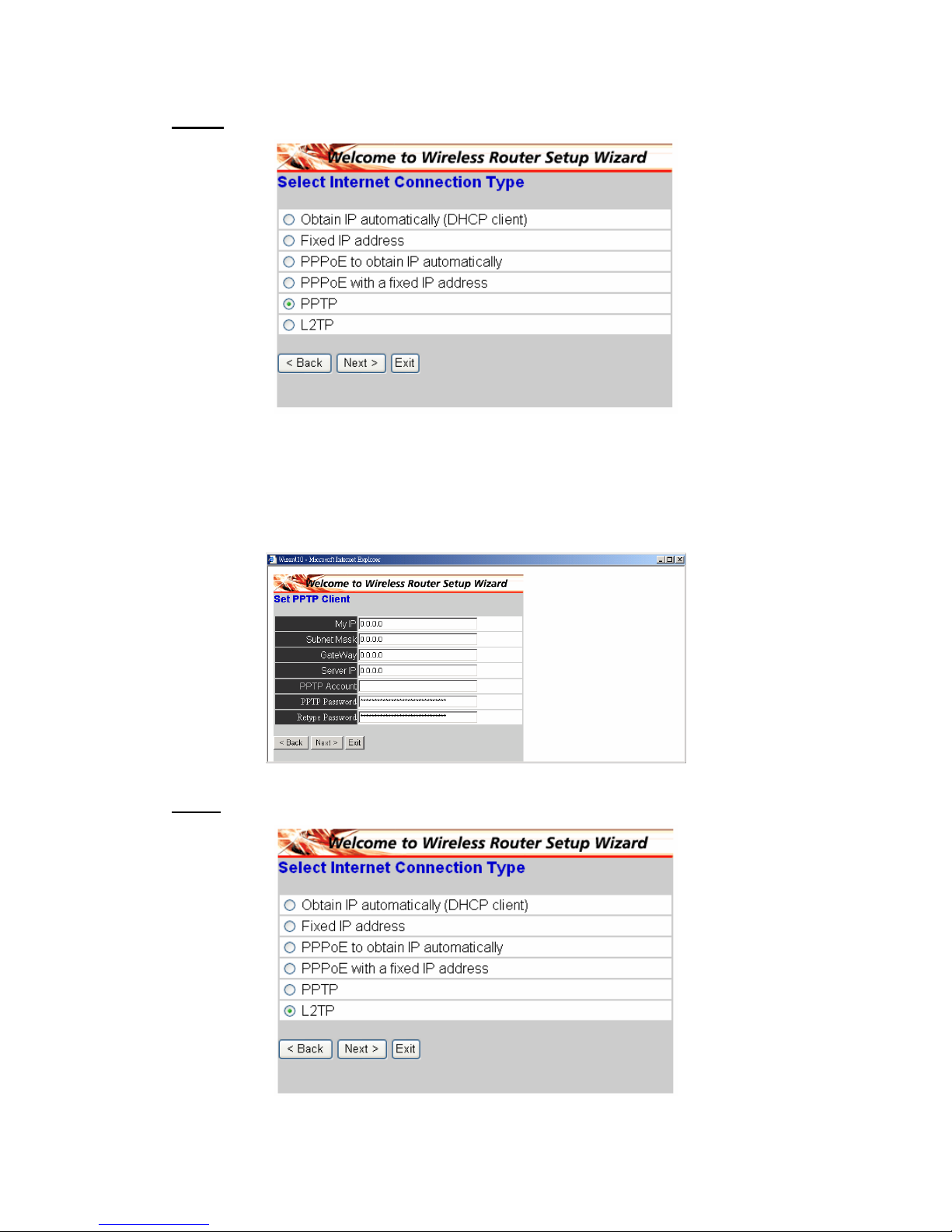
PPTP:
Se il collegamento ad Internet è eseguito usando un modem xDSL (PPTP),
inserire nei campi appropriati: indirizzo IP, Subnet Mask, Gateway, IP del
server, account PPTP, password PPTP e la Subnet Mask richiesta dal provider
(ISP). Se il provider (ISP) ha fornito un identificativo di connessione, inserirlo
nel campo Connection ID (ID di connessione), diversamente lasciarlo su zero.
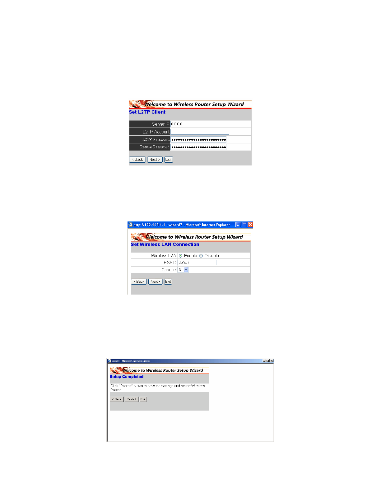
L2TP:
Page 50
47
Se il collegamento ad Internet è eseguito usando un modem L2TP
(connessione remota xDSL), il provider (ISP) fornirà l’IP, l'account e la
password del server. Scegliere questa opzione ed inserire le informazioni
necessarie.
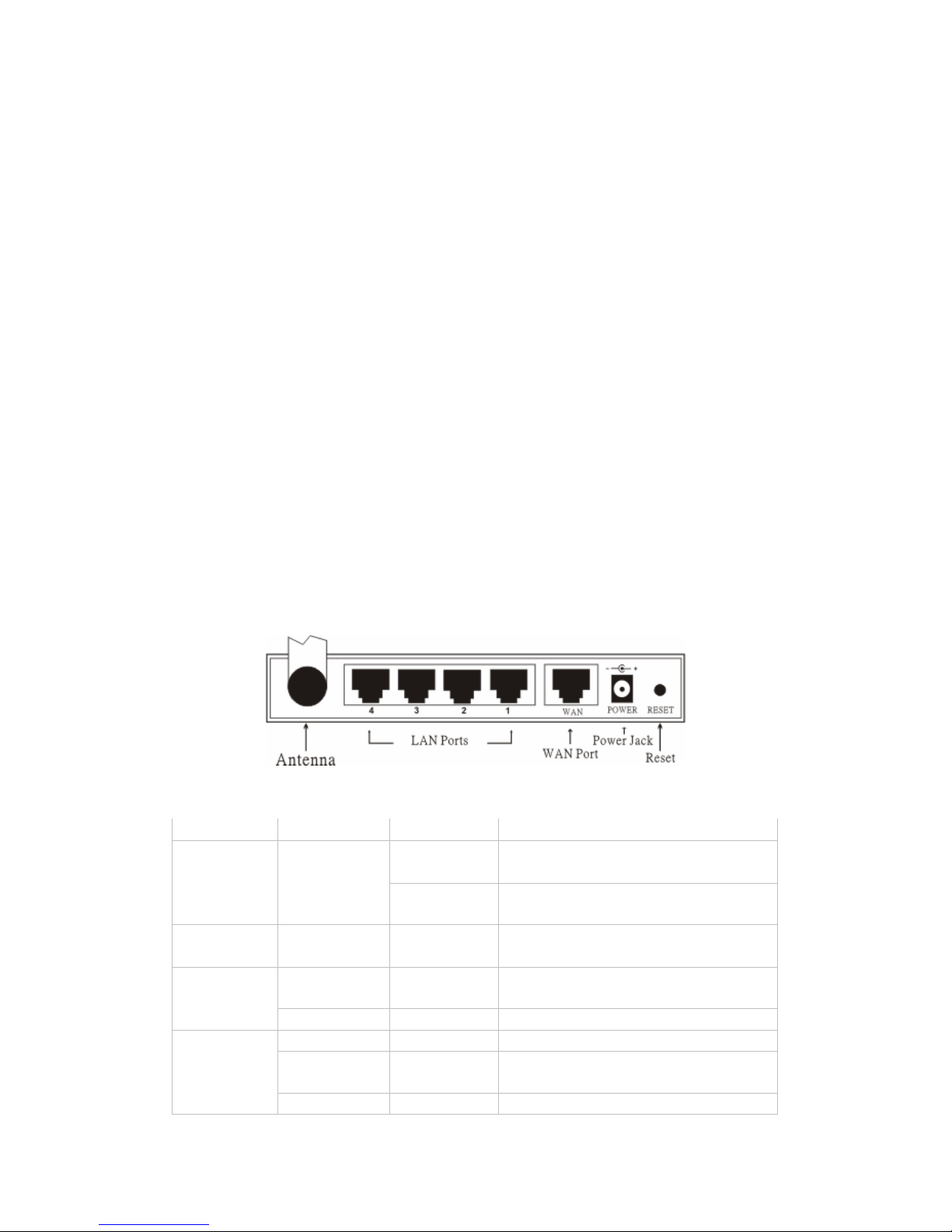
◆ Fase 5: Impostazione della connessione WLAN
Fare clic su "Enable" per abilitare la WLAN. Se si abilita la WLAN, lo SSID
nella casella ti testo e selezionare un canale di comunicazione. Lo SSID ed il
canale devono essere identici a quelli dei dispositivi wireless che tentano la
comunicazione con il router.
◆ Fase 6: Riavvio
La procedura guidata è terminata. Le nuove impostazioni saranno effettive
dopo che il router wireless sarà riavviato. Fare clic su "Restart" per riavviare il
router. Se non si vuole eseguire alcuna modifica, fare clic su "Exit" per uscire
senza salvare le modifiche. Si può anche tornare indietro e modificare le
impostazioni facendo clic su “Back”.
Page 51
48
§ Conectar el enrutador de banda ancha inalámbrico a
su red
1. Conecte el adaptador de alimentación al receptor situado en el panel
posterior. Enchufe el adaptador de alimentación en la toma eléctrica. La
pantalla LED se encenderá para indicar que la operación se ha realizado
correctamente.
2. Apague su módem de cable / DSL. Use un cable Ethernet para conectar el
puerto Ethernet que se encuentra en el módem de cable / DSL y el puerto
WAN situado en el panel posterior de este enrutador. Después de la
conexión, encienda su módem de cable / DSL. El PUERTO WAN se
iluminará para indicar que la operación se ha realizado correctamente
3. Inserte un cable Ethernet en el puerto LAN situado en el panel posterior
del enrutador y utilice un puerto Ethernet disponible en el adaptador de red
del ordenador para configurar el enrutador. La luz LED del puerto LAN 1 se
iluminará para indicar que la conexión se ha realizado correctamente.
4. Reinicie entonces su ordenador.
5. Conecte sus equipos con conexión Ethernet al resto de puertos LAN
Ethernet situados en el panel posterior de este enrutador con los cables
Ethernet adicionales.
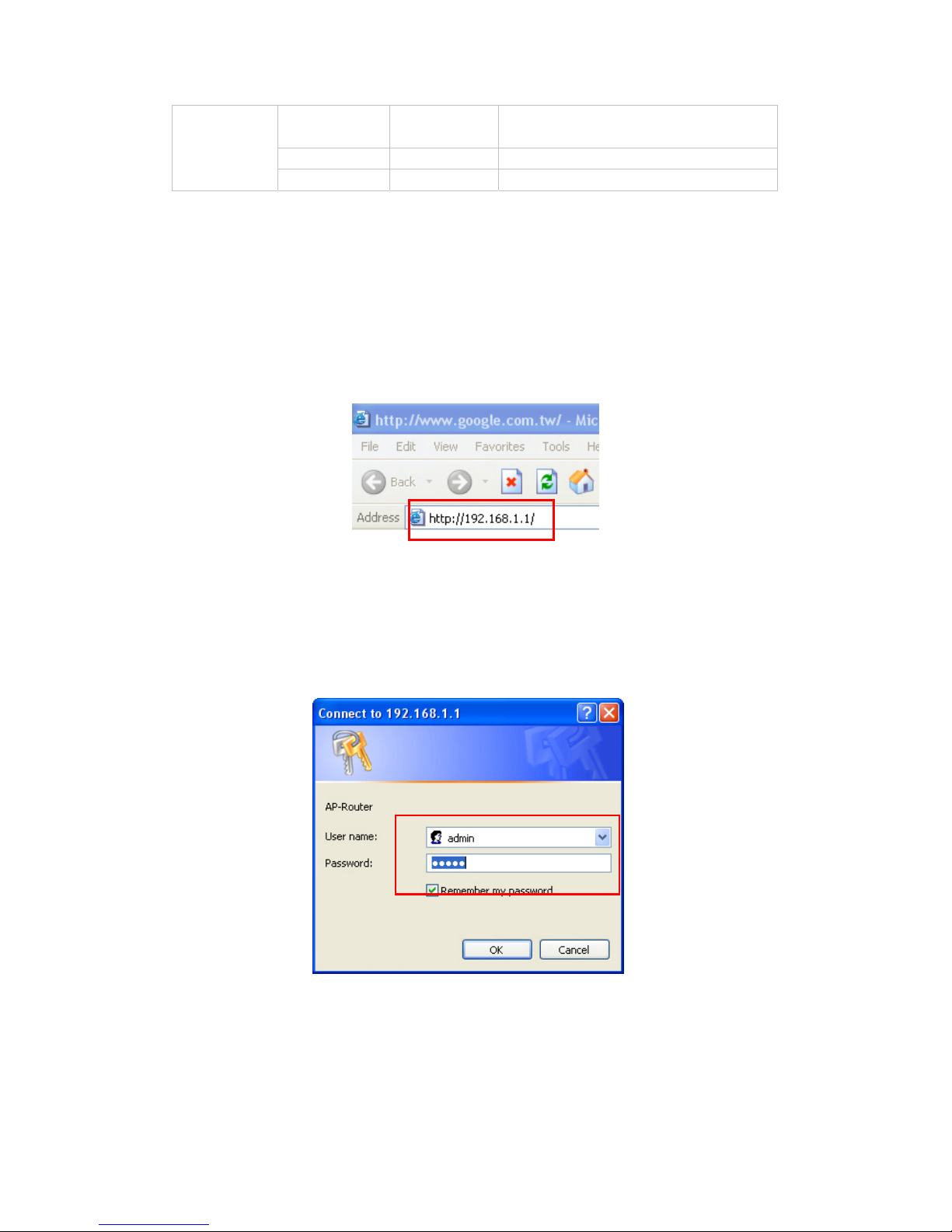
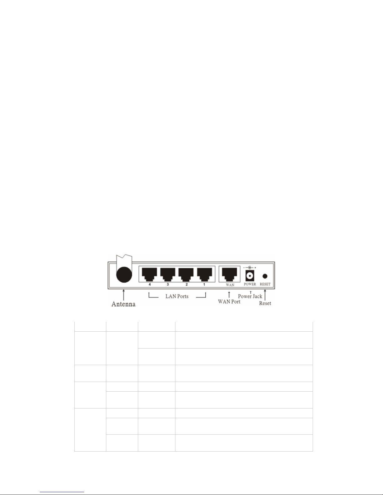
◆ Vista posterior:
◆ Indicadores LED:
LED Color Estado Descripción
Encendido
Indica la conexión correcta de la
fuente de alimentación.
Encendido Verde
APAGADO
La unidad no está recibiendo
alimentación
Estado Verde Encendido
Indica que el dispositivo se
encuentra conectado a la WLAN.
Encendido
Indica la conexión del puerto
WAN
WAN
Intermitente Transmisión de datos.
Encendido El enlace se ha establecido
Encendido Intermitente
Actividad de transmisión o
recepción de paquetes
WLAN
Desactivado – Sin actividad de enlace
Page 52
49
Encendido
Indica que la conexión se ha
establecido.
Encendido Intermitente Transmisiones de datos
LAN
Desactivado – Sin conexión LAN
§ Instalación rápida por medio del Asistente
◆ Abra su navegador Web
Puede acceder al menú de configuración en cualquier momento abriendo una
ventana de navegador y escribiendo la dirección IP del enrutador inalámbrico.
La IP predeterminada es 192.186.1.1
Parpadeará la ventana siguiente. Introduzca el nombre de usuario y la
contraseña. En ambos casos, la palabra predeterminada es "admin".
Ahora aparecerá la pantalla de menú principal.
Page 53
50
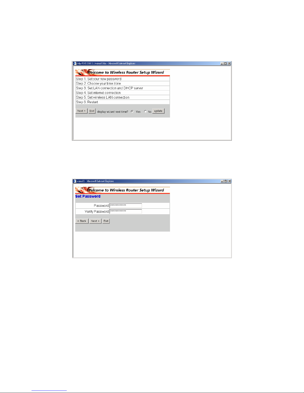
Puede seguir simplemente el proceso paso a paso para configurar su
enrutador inalámbrico en 6 sencillos pasos. Haga clic en “Next” en la pantalla
del Asistente de Instalación para continuar.
◆ Paso 1: Establecer la nueva Contraseña
Puede cambiar la contraseña a la que desee y hacer clic en "Next" para
continuar.
Page 54
51
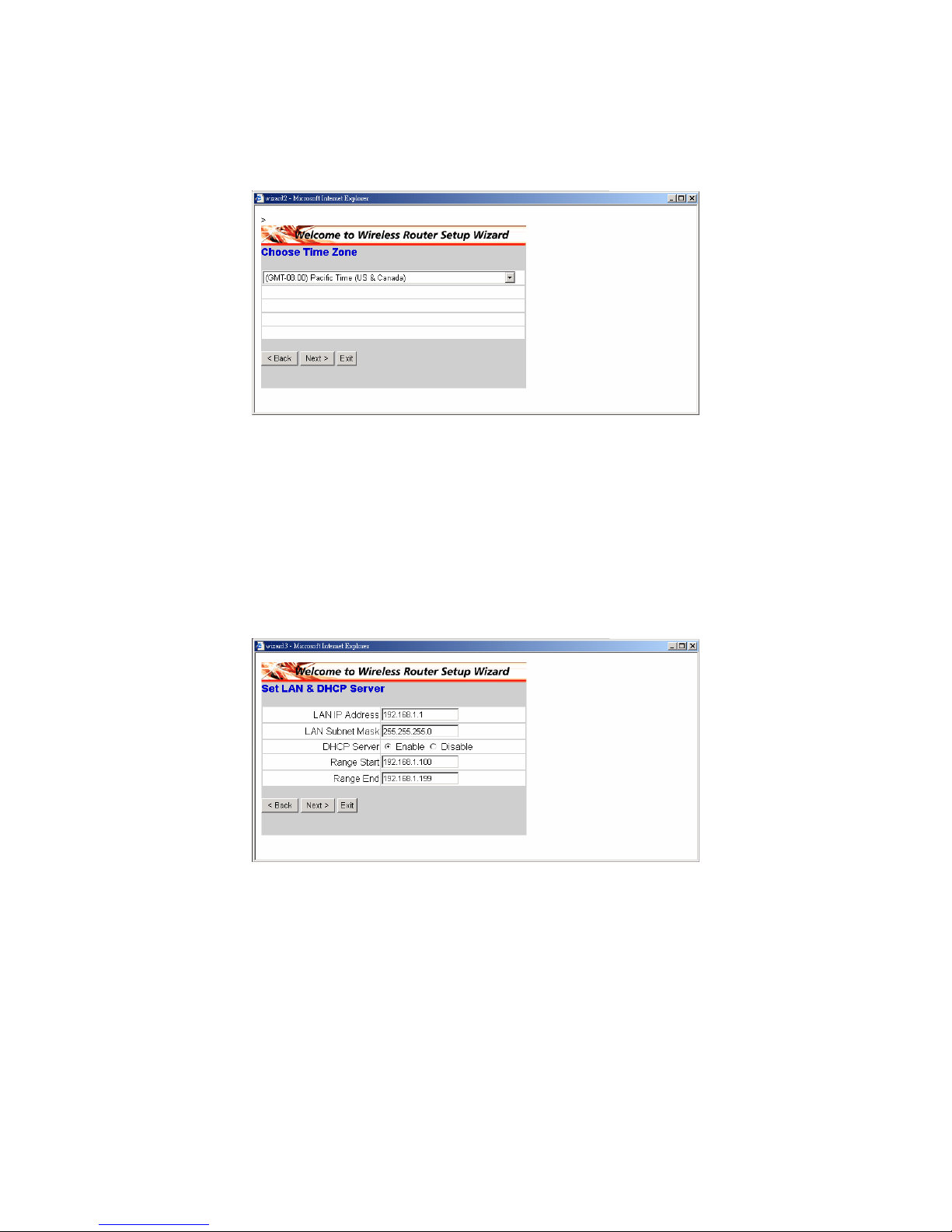
◆ Paso 2: Seleccione su zona horaria
Seleccione su zona horaria en la lista desplegable. Haga clic en “Next” para
continuar.
◆ Paso 3: Configurar la conexión LAN y el servidor DHCP
Establezca su dirección IP y máscara. La IP predeterminada es 192.168.1.1.
Si desea activar DHCP, haga clic en "Enabled". Si activa la función DHCP
podrá asignar automáticamente direcciones IP. Asigne el rango de
direcciones IP en los campos "Range start" y "Range end". Haga clic en
“Next” para continuar.
Page 55
52
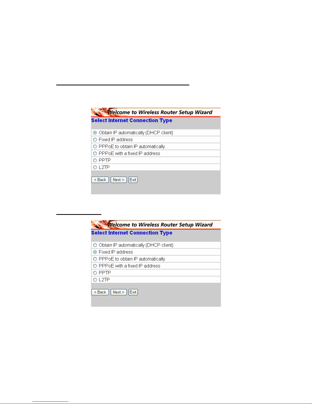
◆ Paso 4: Configurar la conexión a Internet
Seleccione cómo configurará el enrutador la conexión a Internet: IP obtenida
automáticamente; Dirección IP fija; PPPoE para obtener IP automáticamente;
PPPoE con una dirección IP fija, PPTP.
Obtener una IP automáticamente (cliente DHCP):
Si ha activado el servidor DHCP, seleccione "Obtain IP automatically (DHCP
client)" para que el enrutador asigne direcciones IP automáticamente.
Dirección IP fija:
Page 56
53
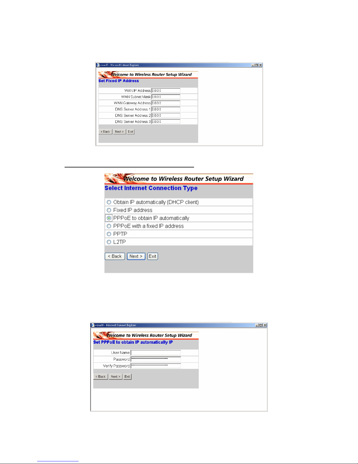
Si se asigna una dirección IP fija, aparecerá la pantalla siguiente. Establezca
la dirección WAN y el servidor DNS.
PPPoE para obtener IP automáticamente:
Si se conecta a Internet utilizando un Módem PPPoE (xDSL de Marcado), el
ISP le entregará un Nombre de usuario y una Contraseña, y utilizará el
protocolo PPPoE. Seleccione esta opción e introduzca la información
necesaria.
Page 57
54
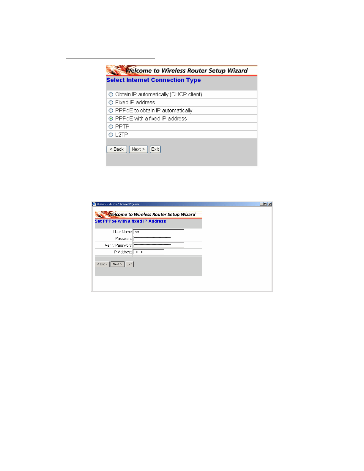
PPPoE con dirección IP fija:
Si se conecta a Internet utilizando un Módem PPPoE (xDSL de Marcado), el
ISP le entregará una Contraseña, un Nombre de usuario y una Dirección IP
fija. Seleccione esta opción e introduzca la información necesaria.
Page 58
55
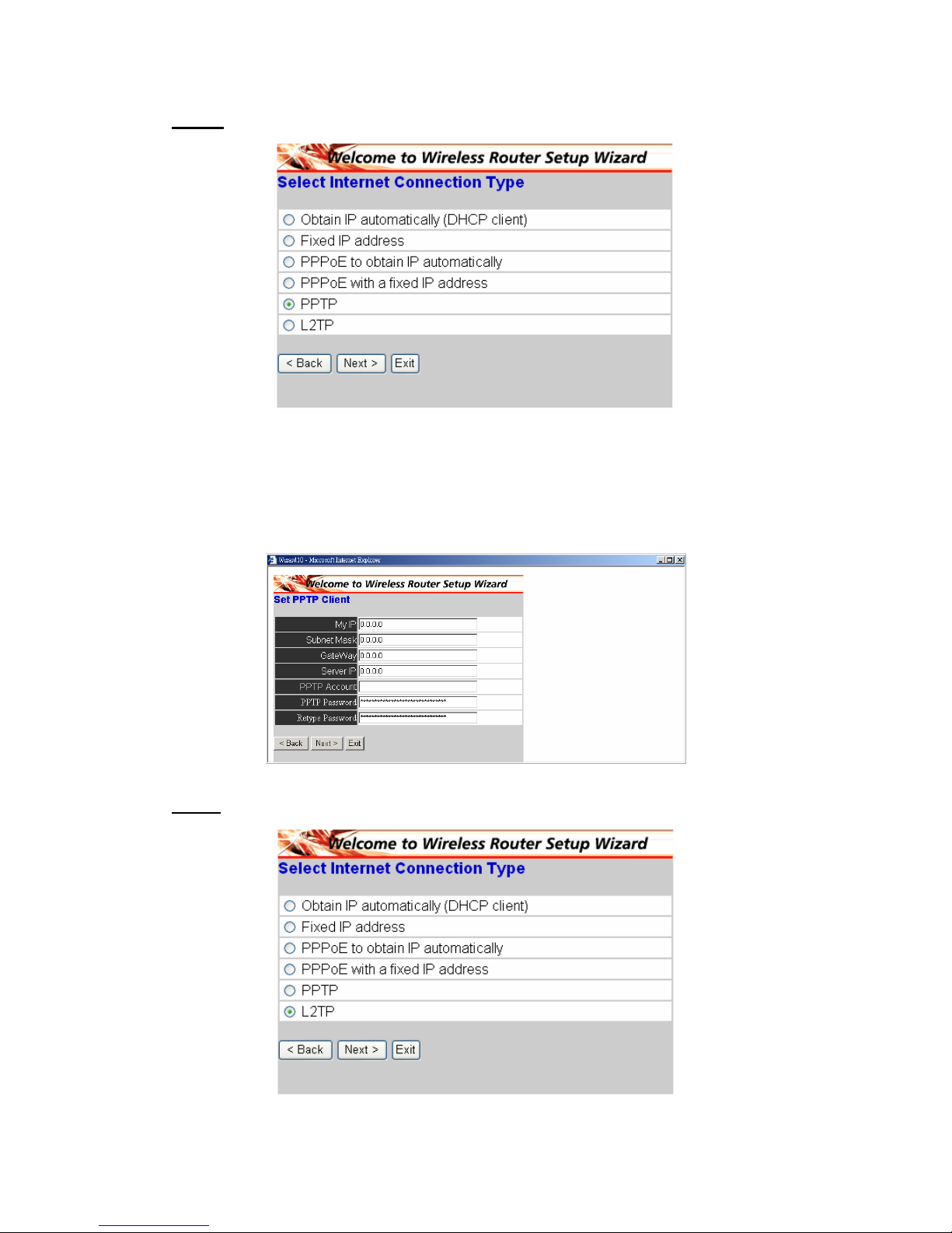
PPTP:
Si se conecta a Internet utilizando un Módem xDSL (PPTP), introduzca su
Dirección IP, Máscara de Subred, Pasarela, IP de Servidor, Cuenta PPTP,
Contraseña PPTP y Máscara de subred en los campos adecuados. Si su ISP
le ha entregado un ID de Conexión, introdúzcalo en el campo "Connection ID".
De no se así, déjelo a cero.
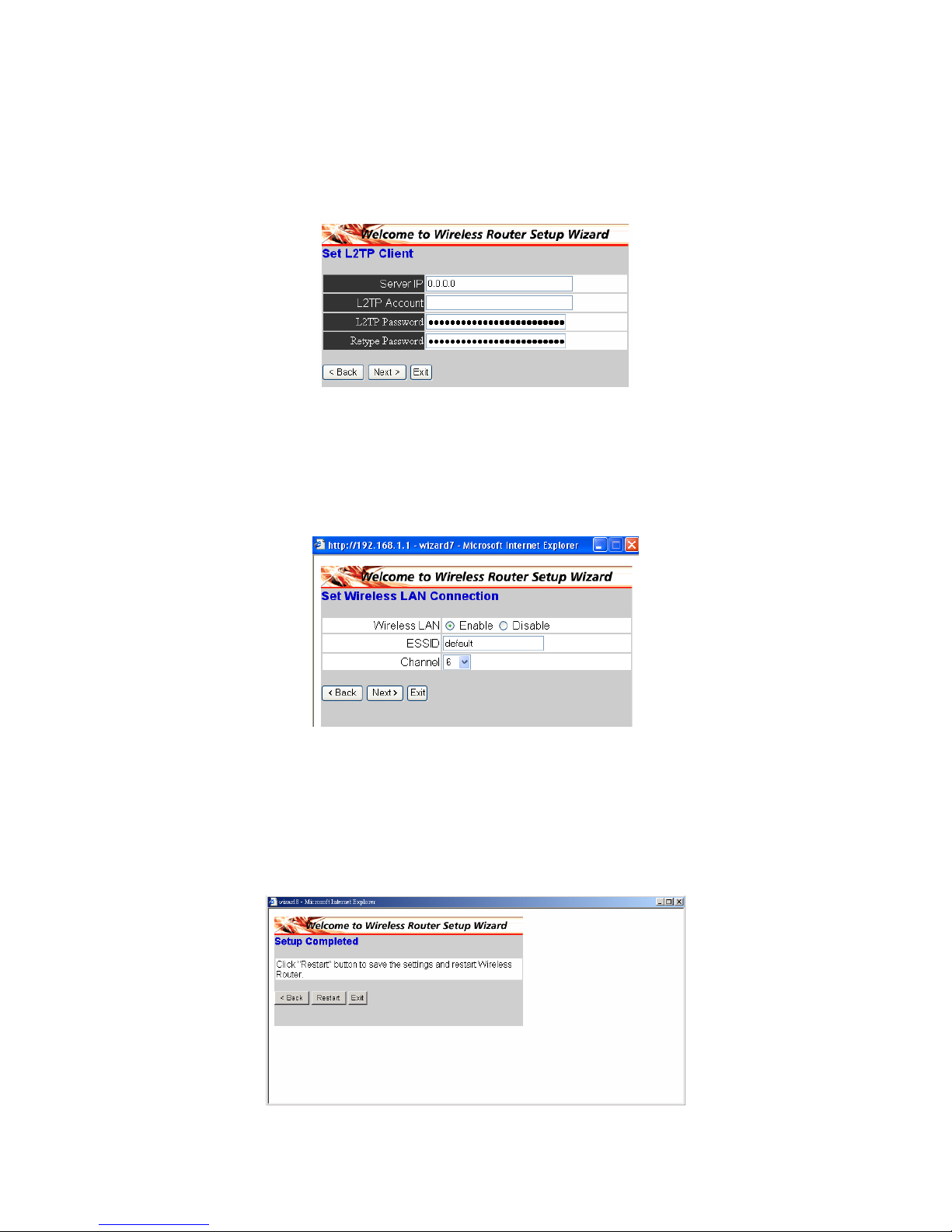
L2TP:
Page 59
56
Si se conecta a Internet utilizando un Módem L2TP (xDSL de Marcado), el ISP
le entregará una IP de Servidor. Account and Password. Seleccione esta
opción e introduzca la información necesaria.
◆ Paso 5: Configurar la conexión LAN Inalámbrica
Haga clic en "enable" para activar la LAN inalámbrica. si activa la LAN
inalámbrica, escriba el SSID en el cuadro de texto y seleccione un canal de
comunicaciones. El SSID y el canal deben ser el mismo que en los
dispositivos inalámbricos que intentes comunicarse con el enrutador.
◆ Paso 6: Reiniciar
El Asistente de Configuración ha finalizado. Las nuevas opciones serán
efectivas después de reiniciar el enrutador inalámbrico. Haga clic en
"Restart" para reiniciar el enrutador. Si no desea hacer ningún cambio, haga
clic en "Exit" para salir sin ningún cambio. También puede volver y modificar
la configuración haciendo clic en "Back".
Page 60
57
§ Ligação do router de banda larga sem fios à rede
1. Ligue o transformador à entrada respectiva que encontra no painel traseiro.
Ligue a outra extremidade do cabo do transformador à tomada eléctrica. O
LED indicador de alimentação acende como sinal de que a ligação foi feita
correctamente.
2. Desligue o modem por cabo/DSL. Utilize um cabo Ethernet para fazer a
ligação entre a tomada Ethernet existente no modem por cabo/DSL e a
porta WAN existente no painel traseiro deste router. Após feita esta ligação,
ligue o modem por cabo/DSL. O LED da porta WAN acende como sinal de
que a ligação foi feita correctamente
3. Utilize um cabo Ethernet para fazer a ligação entre a porta LAN existente no
painel traseiro do router e a porta Ethernet disponível na placa de rede
instalada no computador que será utilizado para configurar o router. O LED
da porta LAN 1 acende como sinal de que a ligação foi feita correctamente.
4. De seguida, reinicie o computador.
5. Ligue os computadores que tiver equipados com Ethernet às restantes
portas LAN existentes no painel traseiro deste router utilizando os cabos
Ethernet adicionais.
◆ Parte de trás:
◆ LEDs indicadores:
LED Cor Estado Descrição
Ligado
Assinala uma correcta ligação à fonte de
alimentação.
Alimen
tação
Verde
Desligado O dispositivo não está a receber
alimentação.
Estado Verde Ligado
Indica que o dispositivo está ligado à
WLAN.
Ligado Assinala a ligação à porta WAN
WAN
Intermite
nte
Transmissão de dados.
Ligado Foi estabelecida ligação
Ligado
Intermite
nte
Transmissão de pacotes ou recepção
WLAN
Desliga
do
— Sem ligação
Page 61
58
Ligado Indica que a ligação foi estabelecida.
Ligado
Intermite
nte
Transmissão de dados
LAN
Desliga
do
— Sem ligação à LAN
§ Configuração rápida através do assistente
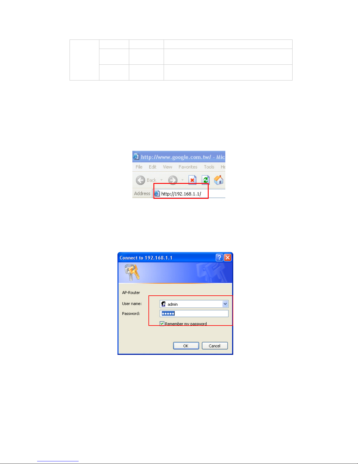
◆ Abra o seu browser da Web
Para aceder ao menu de configuração em qualquer altura, abra uma janela no
browser da web e digite o endereço IP deste router sem fios. O endereço IP
predefinido é 192.168.1.1.
A janela seguinte é apresentada. Introduza o nome de utilizador e a senha.
Em ambos os casos, o nome de utilizador e a senha é "admin"
O ecrã do menu principal é apresentado.
Page 62
59
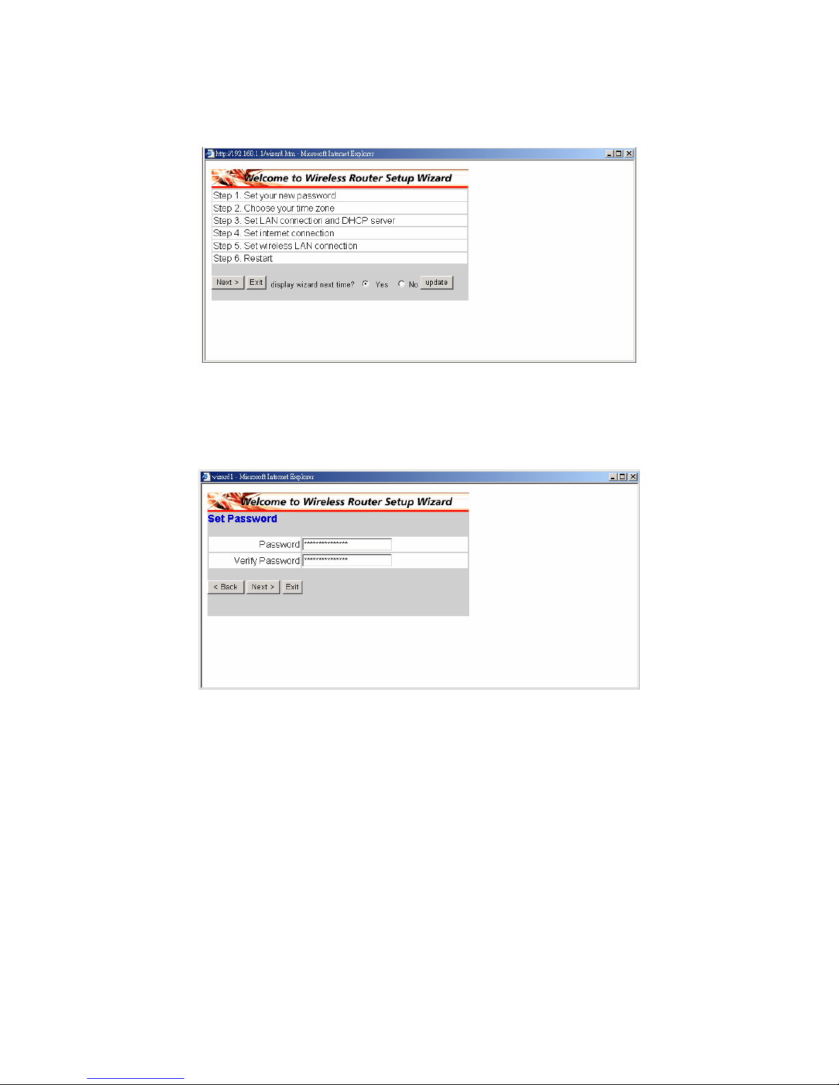
Siga as instruções passo a passo para configurar o seu router sem fios em 6
fáceis etapas. Clique em “Next” no ecrã Setup Wizard para prosseguir.
◆ Etapa 1: Defina a sua nova senha
Pode alterar a senha se assim o pretender e depois clicar em “Next” para
prosseguir.
Page 63
60
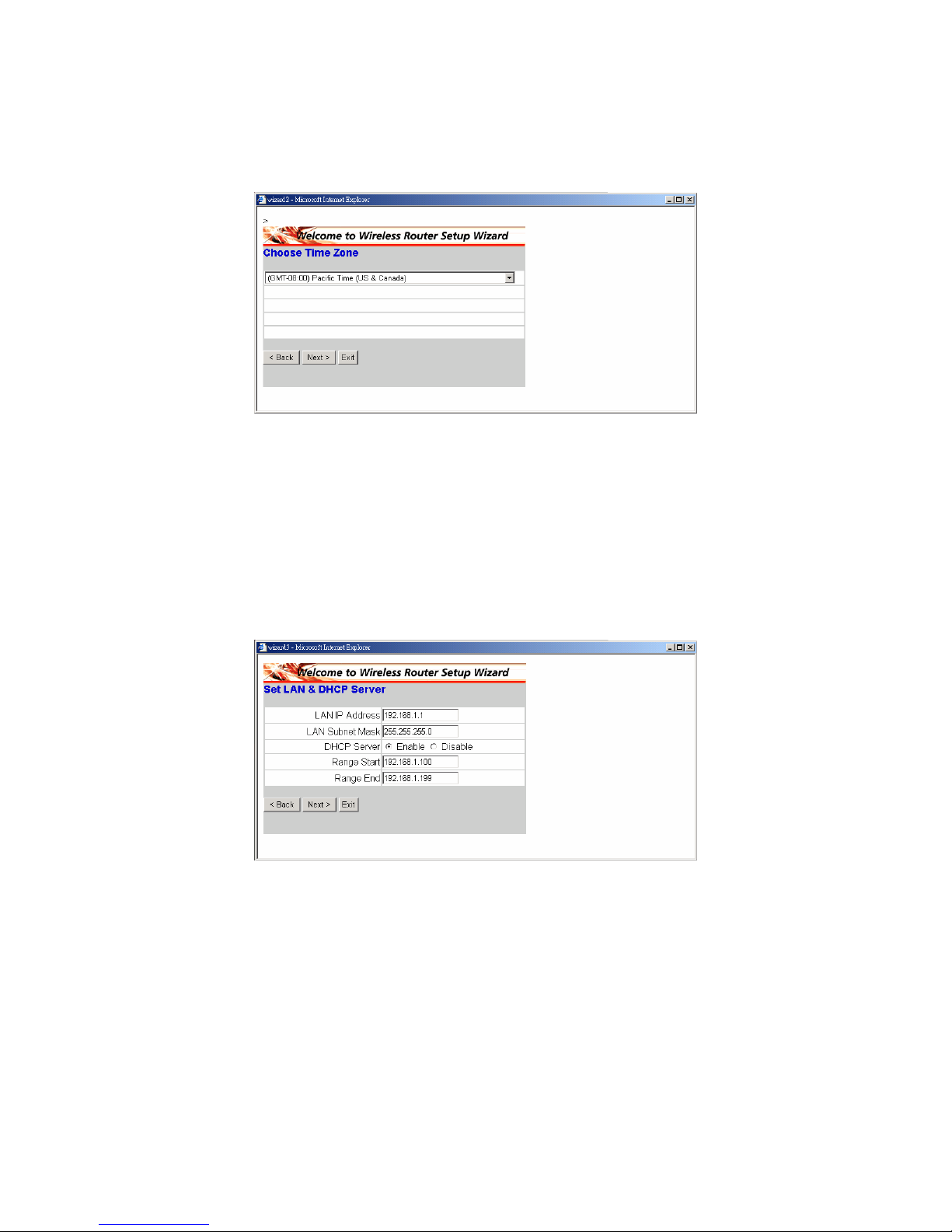
◆ Etapa 2: Seleccione o seu fuso horário
Seleccione o seu fuso horário na lista pendente. Clique em “Next” para
continuar.
◆ Etapa 3: Defina a ligação por LAN e o servidor DHCP
Defina o seu endereço IP e a máscara de sub rede. O endereço IP
predefinido é 192.168.1.1. Se quiser activar o servidor DHCP, clique em
“Enabled”. A activação do servidor DHCP permite a atribuição automática de
endereços IP. Defina o intervalo dos endereços IP nos campos “Range
start” e “Range end”. Clique em “Next” para continuar.
Page 64
61
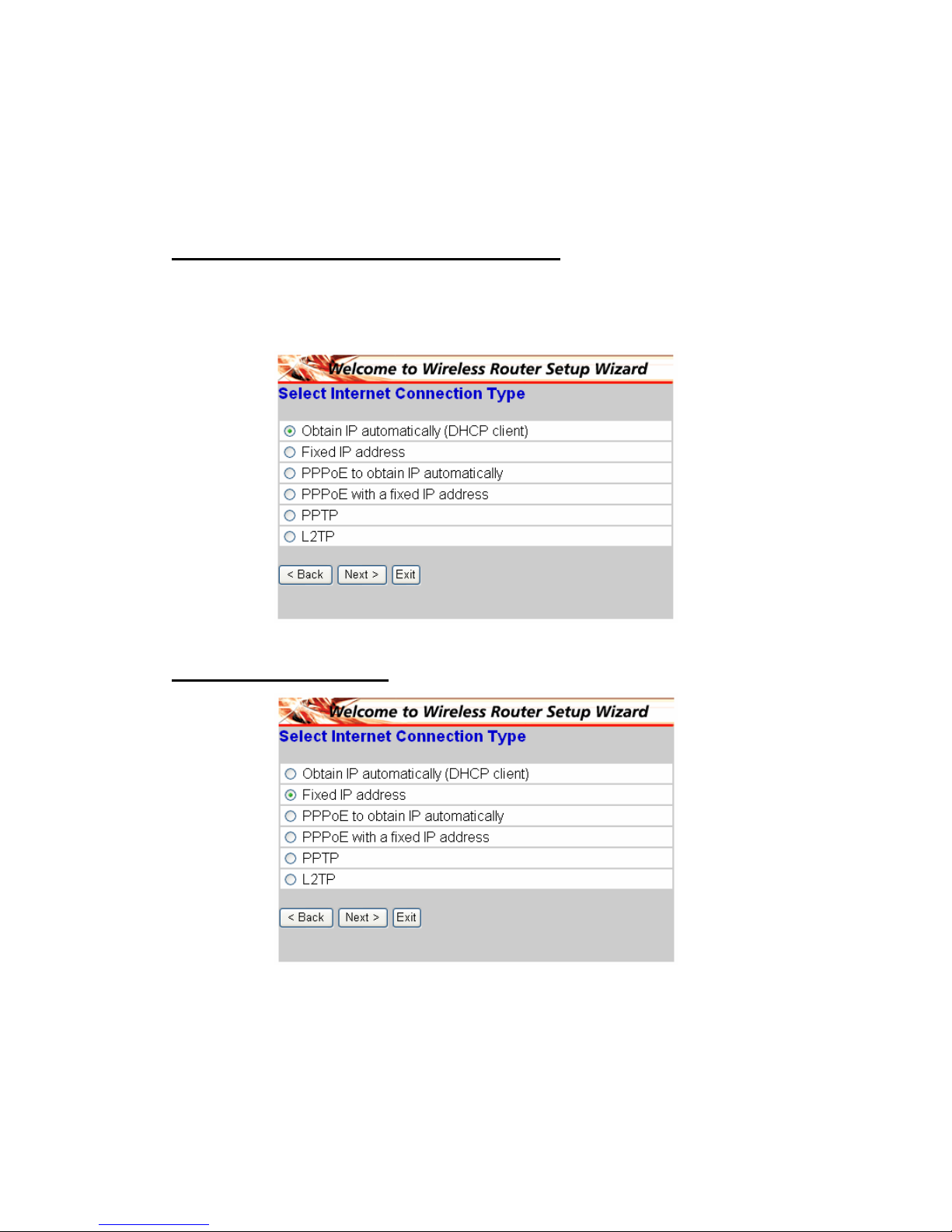
◆ Etapa 4: Definição da ligação à Internet
Seleccione a forma como o router deve aceder à Internet: As opções
disponíveis são as seguintes: Obtain IP automatically; Fixed IP address;
PPPoE to obtain IP automatically; PPPoE with a fixed IP address; PPTP.
A opção Obtain IP automatically (DHCP client):
Caso tenha activado o servidor DHCP, escolha a opção "Obtain IP
automatically (DHCP client)" para que o router proceda à atribuição automática
dos endereços IP.
A opção Fixed IP Address
Page 65
62
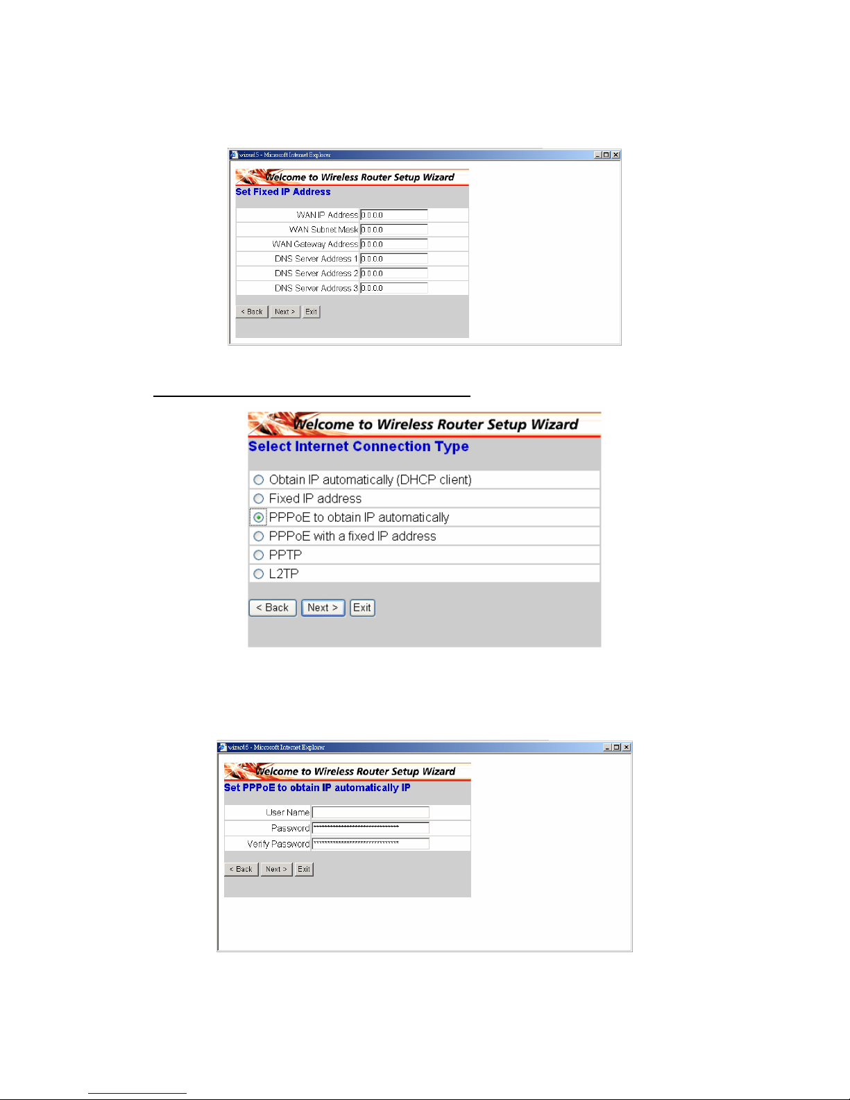
Se escolher a opção Fixed IP address, é apresentado o ecrã seguinte. Defina
o endereço da WAN e do servidor DNS.
A opção PPPoE to obtain IP automatically:
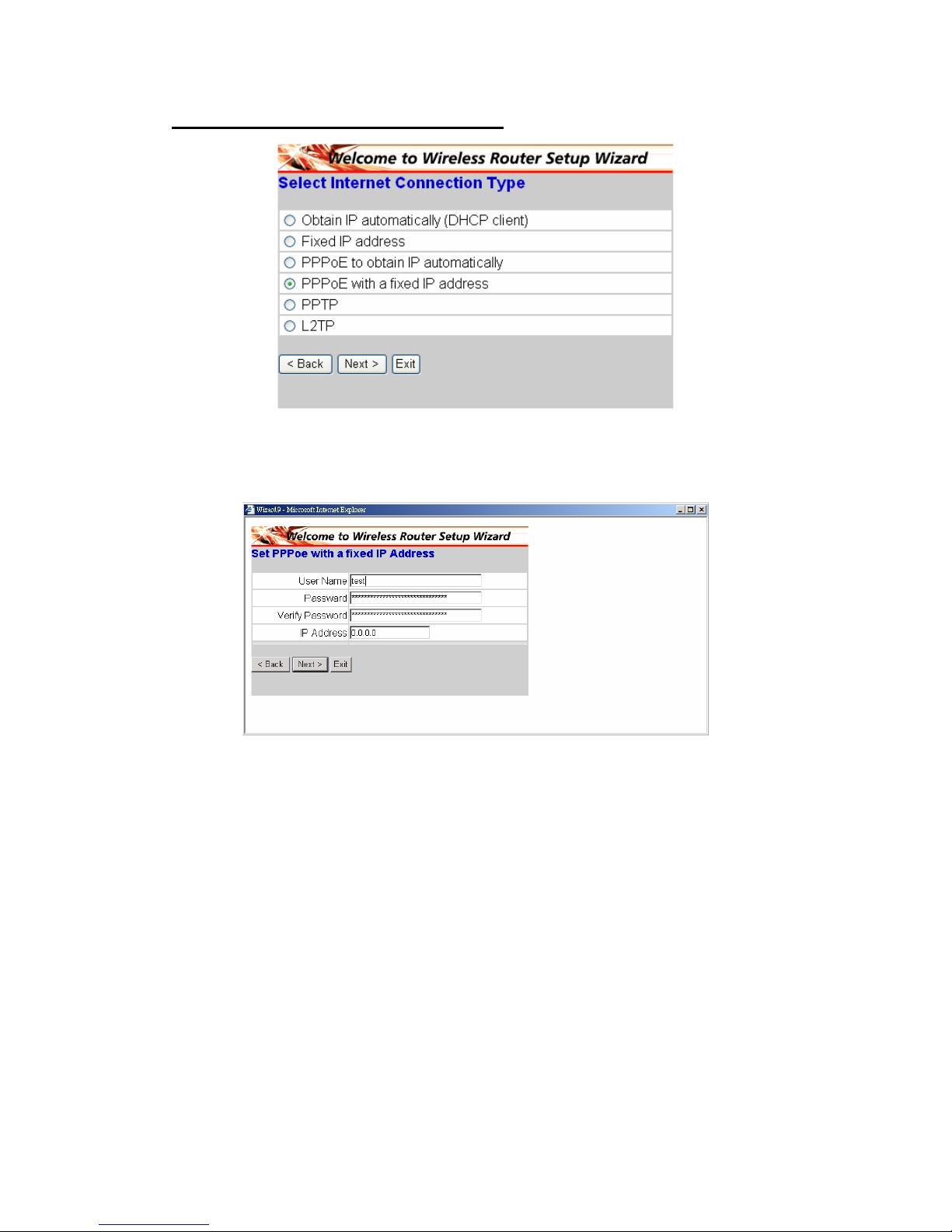
Se ligar à Internet utilizando um modem PPPoE (acesso telefónico por xDSL),
o ISP fornecerá uma senha e um nome de utilizador para que possa utilizar o
protocolo PPPoE. Escolha esta opção e introduza a informação necessária.
Page 66
63
A opção PPPoE with a fixed IP address:
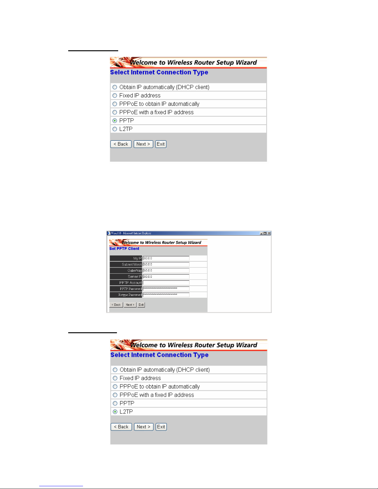
Se ligar à Internet utilizando um modem PPPoE (acesso telefónico por xDSL),
o ISP fornecerá uma senha, um nome de utilizador e um endereço IP fixo.
Escolha esta opção e introduza a informação necessária.
Page 67
64
A opção PPTP:
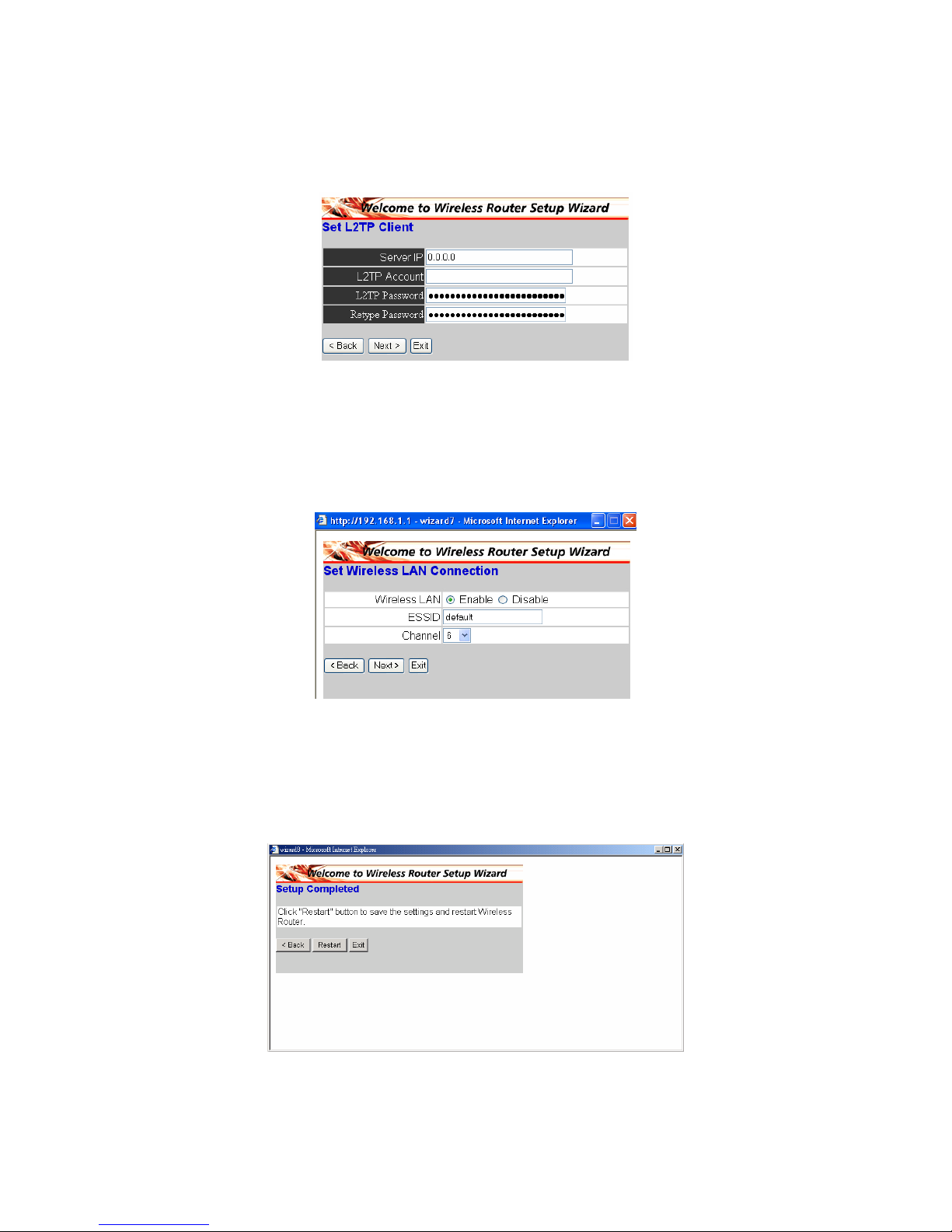
Se ligar à Internet utilizando um modem (PPTP) xDSL, introduza o seu
endereço IP, a máscara de sub rede, o gateway, o servidor IP, o nome da conta
PPTP, a senha PPTP e a máscara de sub rede nos campos apropriados e tal
como pedido pelo seu ISP. Se o seu ISP lhe tiver dado uma ID de ligação,
introduza esta ID no campo Connection ID, caso contrário deixe este campo
vazio.
A opção L2TP:
Page 68
65
Se ligar à Internet utilizando um modem L2TP (acesso telefónico por xDSL), o
ISP fornecerá um endereço de servidor IP, uma conta e uma senha. Escolha
esta opção e introduza a informação necessária.
◆ Etapa 5: Defina a ligação através da LAN sem fios
Clique em “Enable” para activar a LAN sem fios. Se activar a LAN sem fios,
digite o SSID na caixa de texto e seleccione um canal de comunicação. O SSID
e o canal devem corresponder ao SSID e ao canal dos dispositivos sem fios
que estão a tentar comunicar com o router.
◆ Etapa 6: Reiniciar
A configuração fica assim concluída. As novas definições entrarão em vigor
após reiniciar o router sem fios. Clique em “Restart” para reiniciar o router.
Se não quiser fazer quaisquer alterações, clique em “Exit” para sair. Se
quiser voltar atrás e fazer alterações clique em “Back”.
Page 69
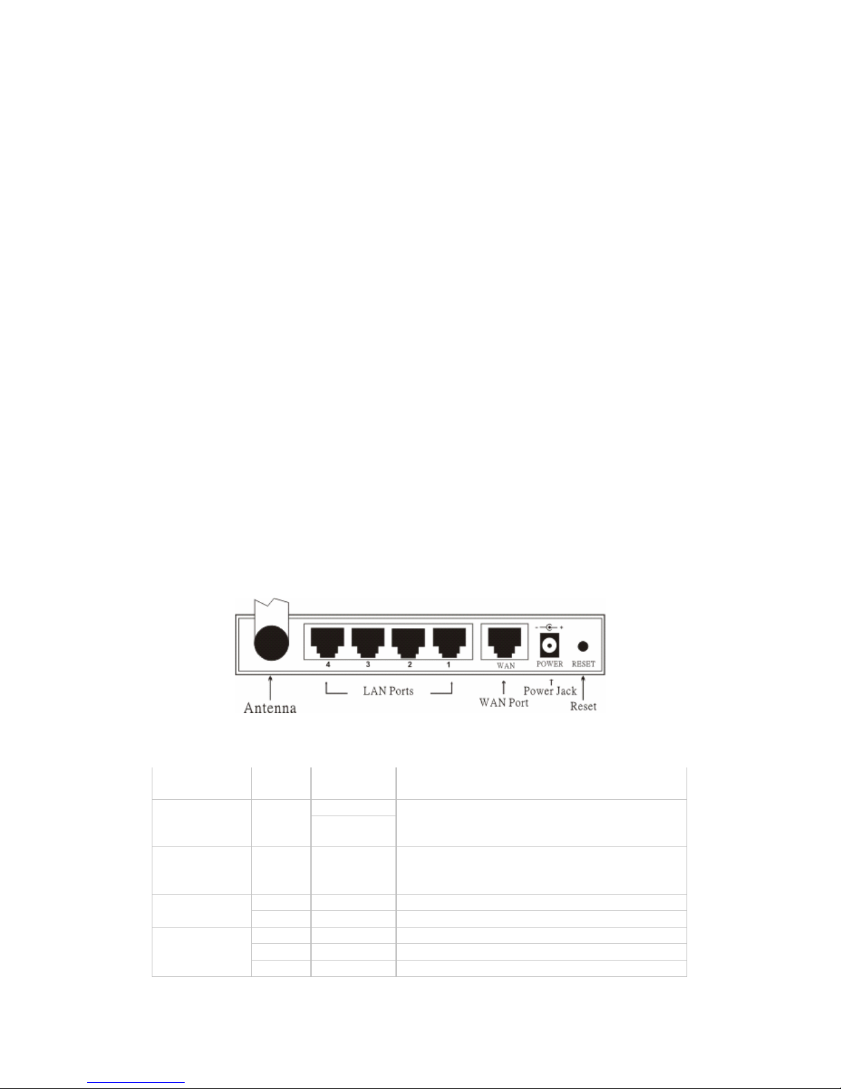
66
§ Подключение беспроводного широкополосного
маршрутизатора к сети
1. Подключите блок питания к гнезду на задней панели. Подключите
блок питания к розетке. Если операция выполнена успешно, загорится
светодиодный индикатор.
2. Отключите питание кабельного или DSL-модема. При помощи
Ethernet-кабеля соедините разъем Ethernet, расположенный на
кабельном или DSL-модеме и порт WAN, расположенный на задней
панели маршрутизатора. Затем включите питание кабельного или
DSL-модема. Порт WAN начнет светиться, обозначая правильную
работу.
3. Подключите Ethernet-кабель к порту локальной сети на задней панели
маршрутизатора и доступному Ethernet-порту сетевого адаптера ПК,
который будет использоваться для настройки маршрутизатора.
Индикатор порта локальной сети 1 начнет светиться, указывая на
правильное соединение.
4. Затем перезагрузите компьютер.
5. Подключите ПК, оснащенные Ethernet, к оставшимся Ethernet-портам
локальной сети на задней панели маршрутизатора при помощи
дополнительных Ethernet-кабелей.
◆ Вид сзади
◆ Индикаторы
Индикатор Цвет Состоян
ие
Описание
Вкл. Питание Зелен
ый
ВЫКЛ.
Означает правильное подключение к
блоку питания.
На устройство не поступает питание.
Состояние Зелен
ый
Вкл. Означает, что устройство
подключено к беспроводной
локальной сети.
Вкл. Означает подключение к порту WAN WAN
Мигает Передача данных.
Вкл. Связь установлена.
Вкл. Мигает Передача или получение пакетов.
WLAN
Выкл. — Связь отсутствует
Page 70
67
Вкл. Означает, что соединение
установлено.
Вкл. Мигает Передача данных.
LAN
Выкл. — Отсутствует соединение с локальной
сетью.
§ Мастер быстрой установки
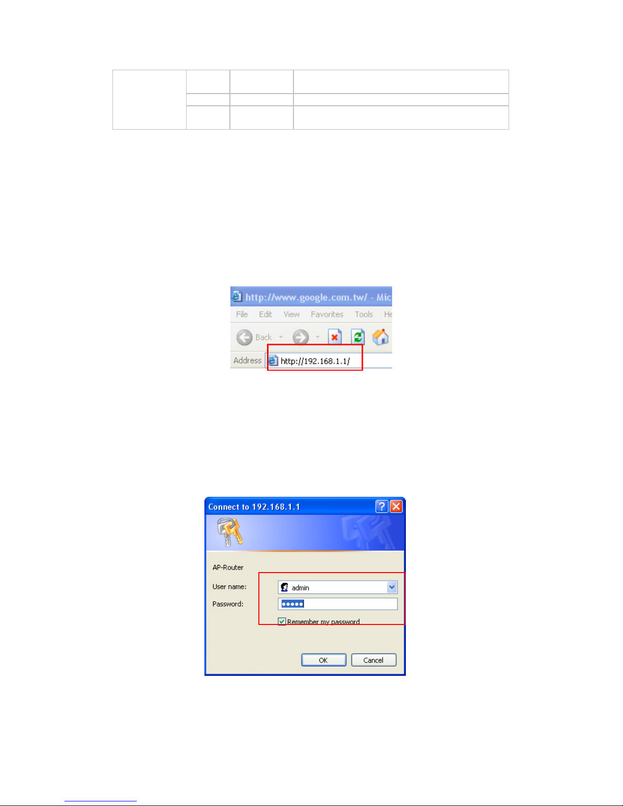
◆ Запустите веб-браузер
Доступ к меню конфигурации можно получить в любой момент, напечатав
в окне веб-браузера IP-адрес данного беспроводного маршрутизатора.
Стандартный IP-адрес – 192.168.1.1.
Отобразится окно, приведенное на иллюстрации. Введите имя
пользователя и пароль. Стандартное значение имени пользователя и
пароля – «admin».
Затем отобразится окно главного меню.
Page 71
68
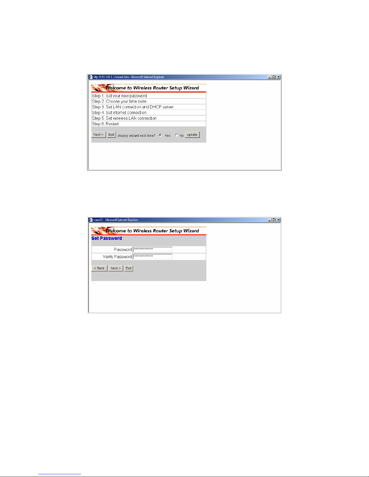
Следуйте инструкциям и выполните 6 шагов процедуры настройки
беспроводного маршрутизатора. Нажмите «Next» в окне мастера
настройки, чтобы продолжить.
◆ Шаг 1. Установка нового пароля
Измените пароль и нажмите кнопку «Next», чтобы продолжить настройку.
Page 72
69
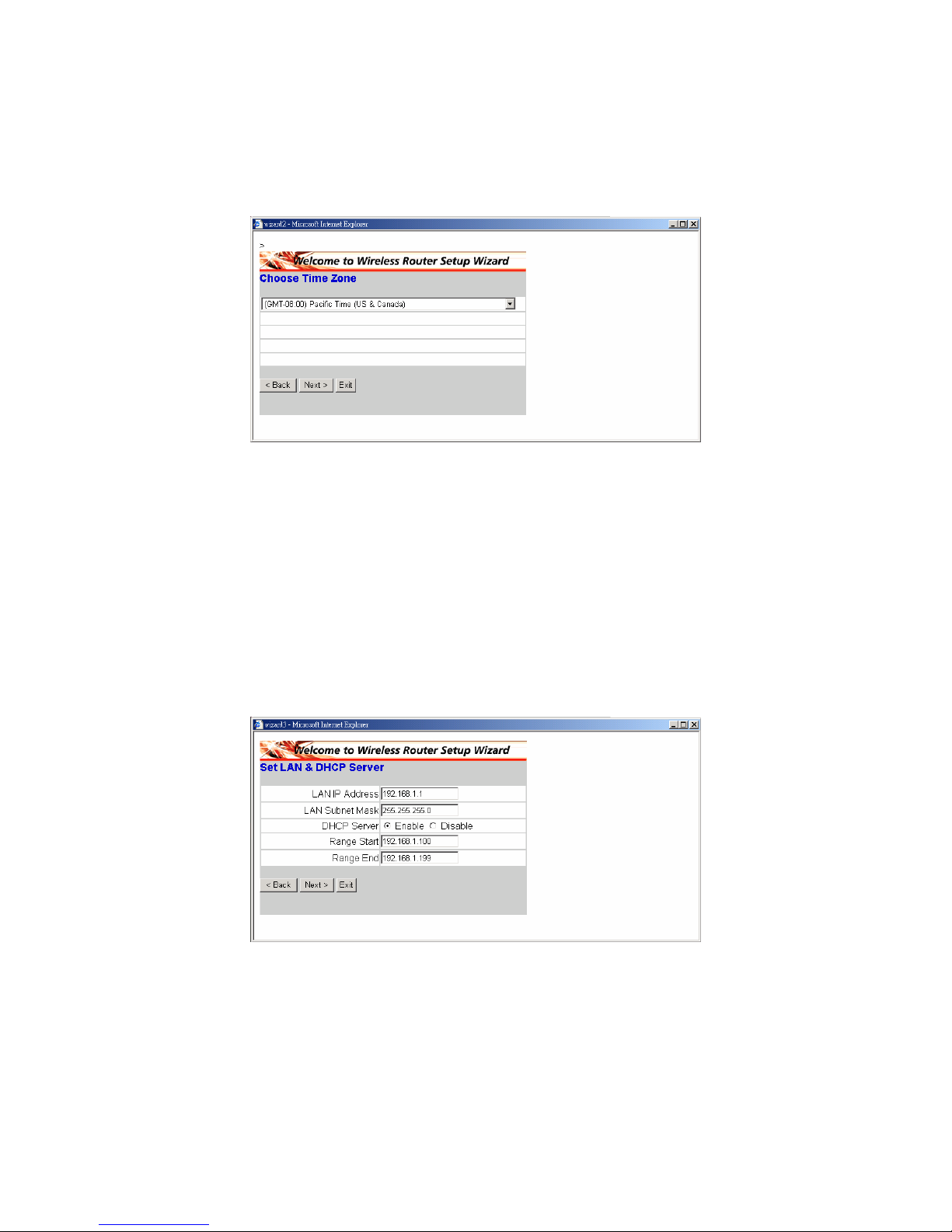
◆ Шаг 2. Выбор часового пояса
Выберите часовой пояс из раскрывающегося списка. Для продолжения
нажмите кнопку «Next».
◆ Шаг 3. Настройка соединения по локальной сети и
DHCP-сервера
Настройте IP-адрес и маску подсети. Стандартный IP-адрес –
192.168.1.1. Нажмите «Enabled» для включения DHCP. Включение
протокола DHCP позволяет автоматически назначать IP-адреса. В
полях «Range start» и «Range end» назначьте диапазон IP-адресов.
Для продолжения нажмите кнопку «Next».
Page 73
70
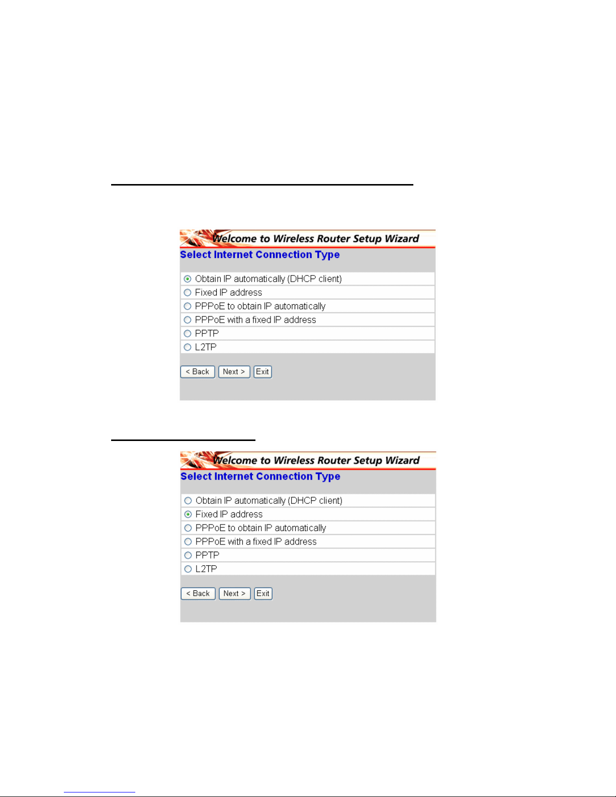
◆ Шаг 4. Настройка подключения к сети Интернет
Выберите способ установки подключения к сети Интернет: Obtained IP
automatically; Fixed IP address; PPPoE to obtain IP automatically; PPPoE
with a fixed IP address; PPTP.
Автоматическое назначение IP-адреса (клиент DHCP)
Если сервер оснащен протоколом DHCP выберите «Obtain IP
automatically», чтобы маршрутизатор назначал IP-адреса автоматически.
Фиксированный IP-адрес
Page 74
71
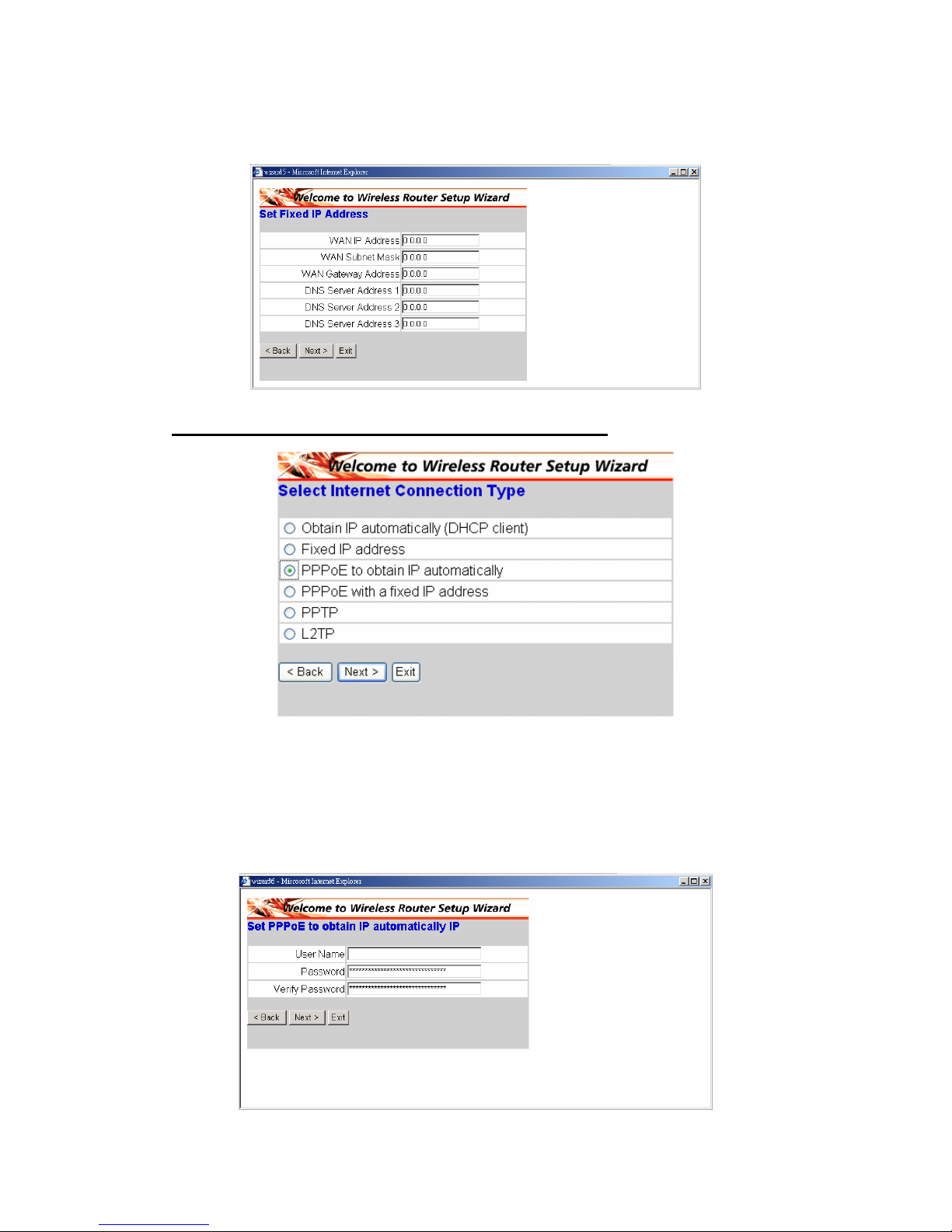
При назначении фиксированного IP-адреса отображается следующее
окно. Назначьте WAN address и DNS server.
PPPoE для автоматического получения IP-адреса
При подключении к сети Интернет при помощи PPPoE-модема
Интернет-провайдер предоставит пароль и имя пользователя, после чего
Интернет-провайдер предоставит подключение к сети Интернет по
протоколу PPPoE. Выберите эту опцию и введите необходимую
информацию.
Page 75
72
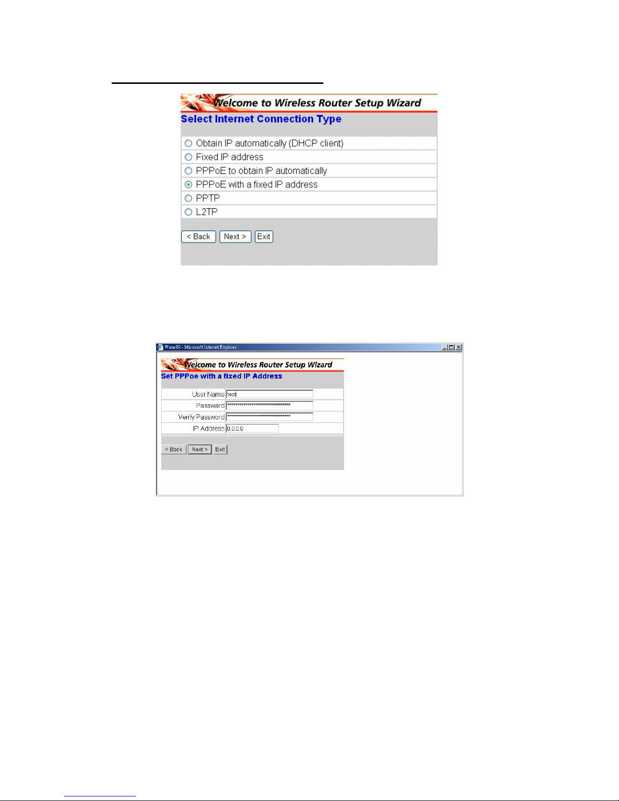
PPPoE с фиксированным IP-адресом
При подключении к сети Интернет при помощи PPPoE-модема
Интернет-провайдер предоставит пароль, имя пользователя и
фиксированный IP-адрес, выберите эту опцию и введите необходимую
информацию.
Page 76
73
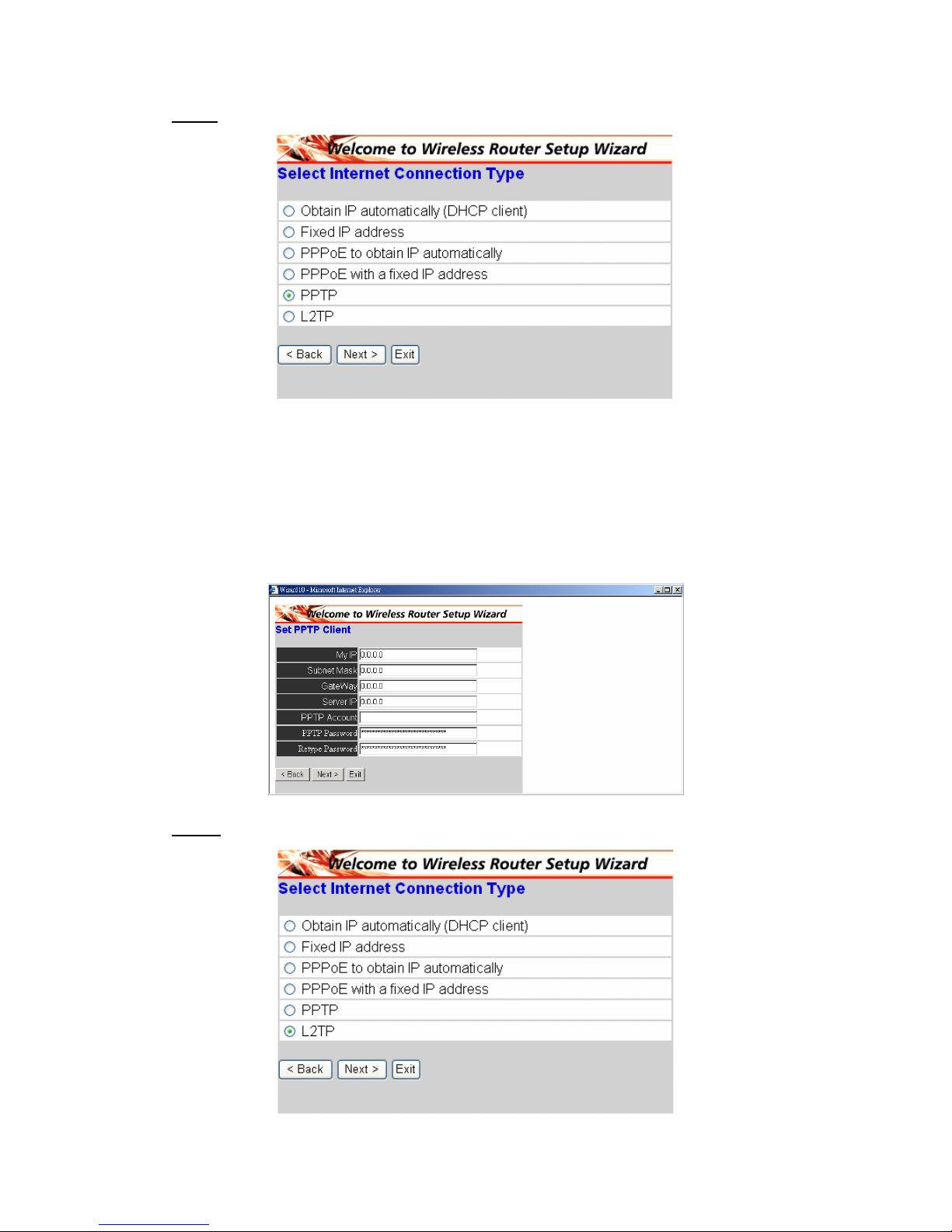
PPTP
При подключении к сети Интернет при помощи xDSL-модема (PPTP),
введите IP-адрес, маску подсети, шлюз, IP-сервер, учетную запись PPTP
и PPTP-пароль. Интернет-провайдер требует указать маску подсети в
некоторых полях. Если Интернет-провайдер предоставил идентификатор
соединения, введите его в поле «Connection ID», в противном случае
оставьте нулевое значение.
L2TP:
Page 77
74
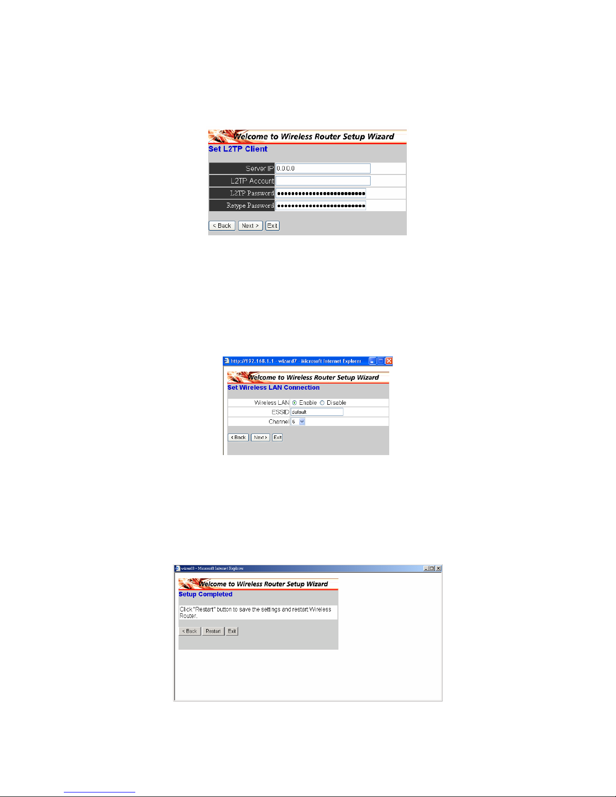
При подключении к сети Интернет при помощи L2TP-модема (для
коммутируемого доступа или xDSL) Интернет-провайдер предоставит
IP-адрес сервера, учетную запись и пароль. Выберите эту опцию и
введите необходимую информацию.
◆ Шаг 5. Настройка беспроводного подключения к локальной
сети
Нажмите «Enable» для включения беспроводной локальной сети. Если
включена беспроводная локальная сеть, введите в текстовом поле SSID и
выберите канал связи. SSID и канал должны совпадать со значениями,
заданными на беспроводных устройствах, которые пытаются
подключиться к маршрутизатору.
◆ Шаг 6. Перезапуск
Работа мастера установки завершена. Новые настройки вступят в силу
после перезапуска беспроводного маршрутизатора. Нажмите кнопку
«Restart» для перезагрузки маршрутизатора. Для выхода без внесения
изменений нажмите кнопку «Exit». Для возврата к изменениям настроек
нажмите кнопку «Back».
Page 78
75
§ 將無線寬頻路由器連接網路
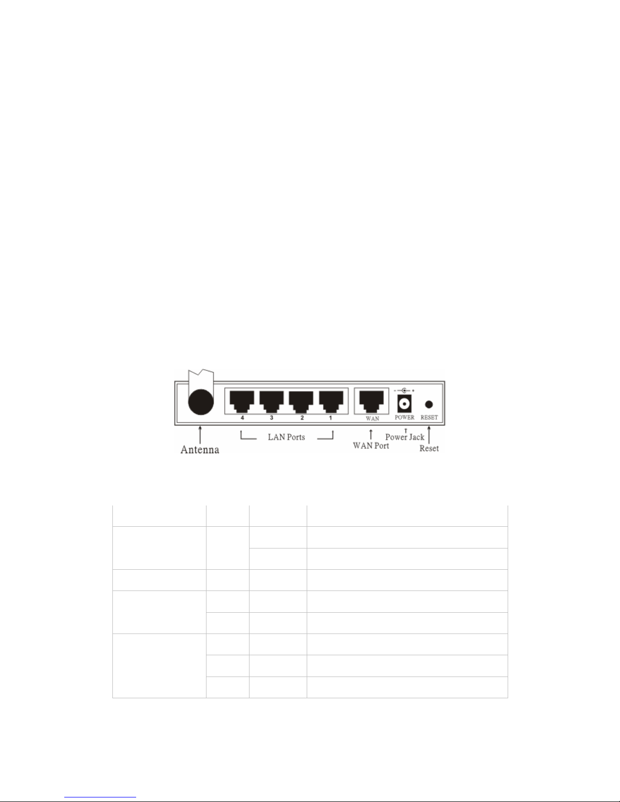
1. 將電源接頭連接接收器背面的面板。 將插頭連接電源插座。 電源LED將會
亮起,代表運作一切正常。
2. 請關閉您電纜/DSL數據機的電源。 使用乙太網路纜線連接纜線/DSL數據
機上的乙太網路插口和本無線路由器背面面板上的無線網路接埠。 完成連接
後,請開啟電纜/DSL數據機電源。 無線網路接埠將會亮起,代表運作正常。
3. 將乙太網路纜線的一端插入路由器背面面板上的區域網路(LAN)接埠,另一
端插入電腦上用來設定路由器的乙太網路卡接埠。 區域網路接埠1(LAN port
1)的LED燈會亮起,代表連接正確。
4. 然後請重新啟動電腦。
5. 請使用其他的乙太網路纜線,將具備乙太網路功能的電腦連接本路由器背面
面板上剩下的乙太網路區域接埠。
◆ 背面圖
LED◆ 指示燈
LED
顏色 狀態 說明
執行中 代表電源供應的連接正常
電源 綠
關閉 本機無電源供應中
狀態 綠 執行中 代表裝置已連上無線行動網路
開啟
代表已連接無線網路埠
無線網路
閃爍 資料傳輸中
開啟
已建立連線
開啟 閃爍 傳輸或接收封包中
無線行動網路
關閉
—
沒有任何連接活動中
Page 79
76
開啟
代表已建立連線
開啟 閃爍 資料傳輸中
區域網路
關閉
—
無任何區域連接
§ 利用精靈快速設定
◆ 開啟網路瀏覽器
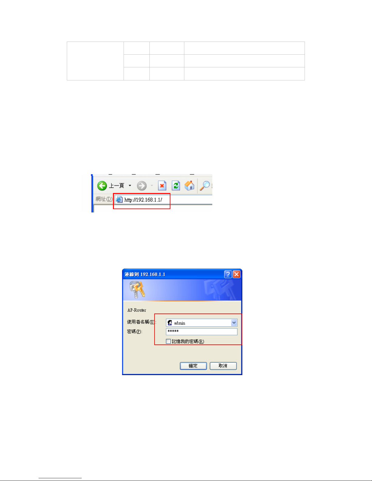
您可以開啟網路瀏覽器,並鍵入本無線路由器的IP位址,隨時連接至設定選單。
預設IP為192.168.1.1。
會彈出以下視窗。 請輸入使用者名稱及密碼。 兩者皆為 「admin」。
隨後彈出的是主選單畫面。
Page 80
77
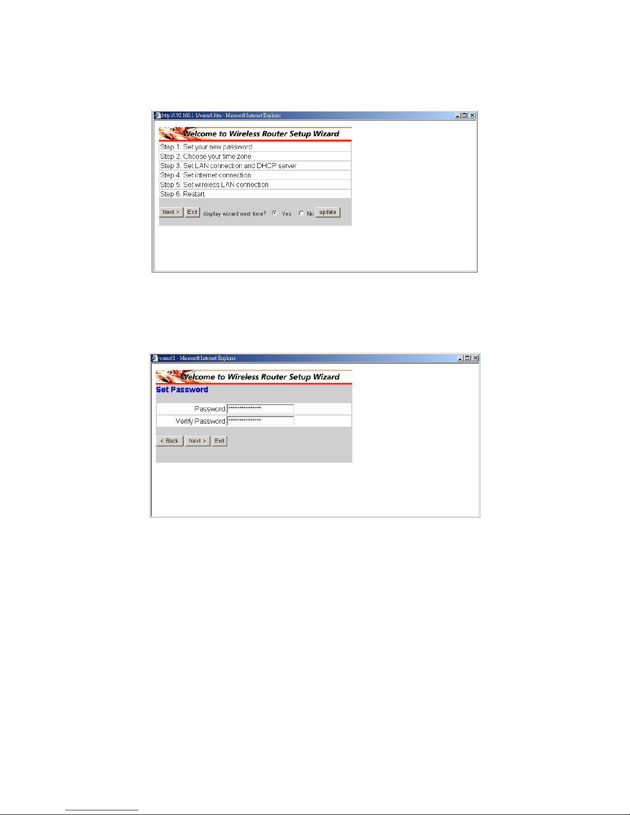
您可以依照簡易的六個步驟,完成設定您的無線路由器。
請按一下設定精靈(Setup Wizard)畫面上的下一步「Next」,繼續設定。
◆ 步驟 1: 設定密碼
您可以隨意變更密碼,然後按一下「Next」繼續。
Page 81
78
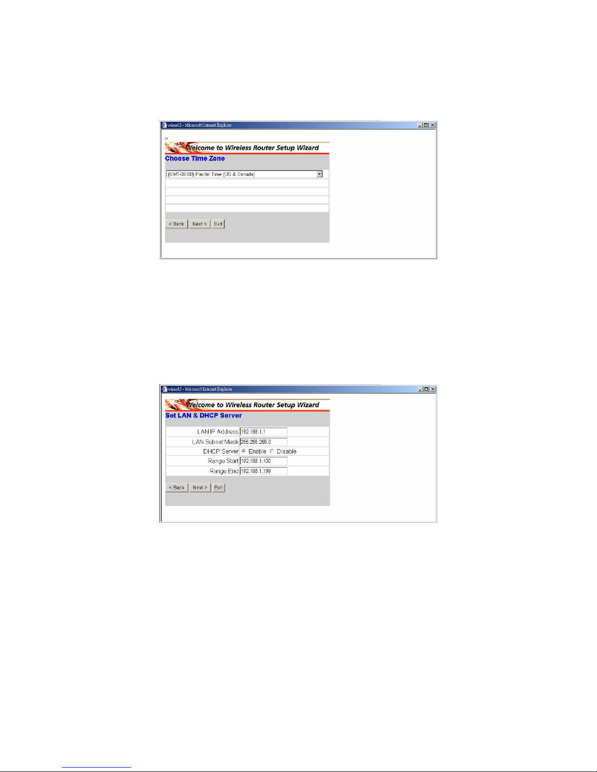
◆ 步驟2: 選擇時區
請從下拉式選單中選擇所在的時區。 請按一下「Next」,繼續設定。
◆ 步驟 3: 設定區域網路連線和DHCP伺服器
設定IP位址和網路遮罩預設IP為192.168.1.1。 若要啟用DHCP,請按一下
「Enabled」。 啟用DHCP可自動指派IP位址。 請在「Range start」和「Range
end」欄位中,指派IP位址的範圍。 請按一下「Next」,繼續設定。
Page 82
79
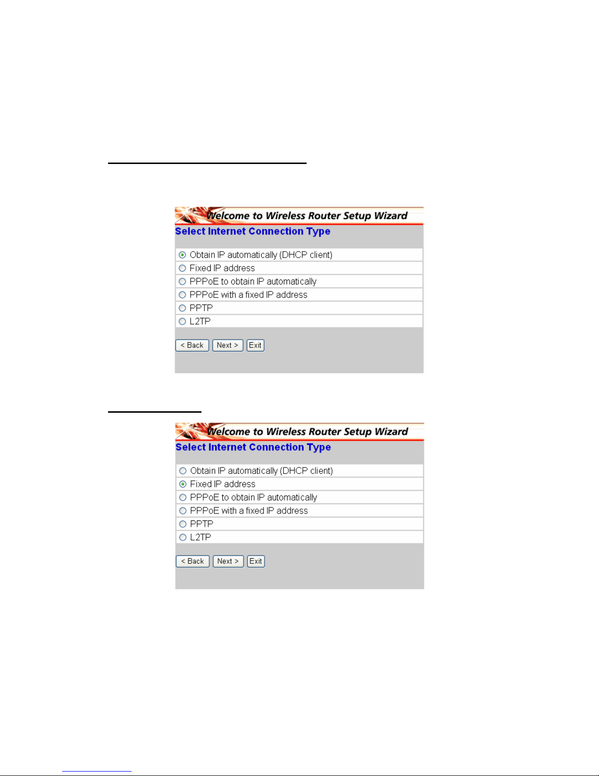
◆ 步驟 4: 設定網際網路連線
選擇路由器設定網際網路的方式: 自動取得IP;固定IP位址;由PPPoE自動取
得IP;固定IP位址的PPPoE;PPTP。
Obtain IP automatically (DHCP client):
若已啟用DHCP伺服器,請選擇「Obtain IP automatically (DHCP client)」,以便
路由器自動指派IP位址。
Fixed IP Address:
Page 83
80
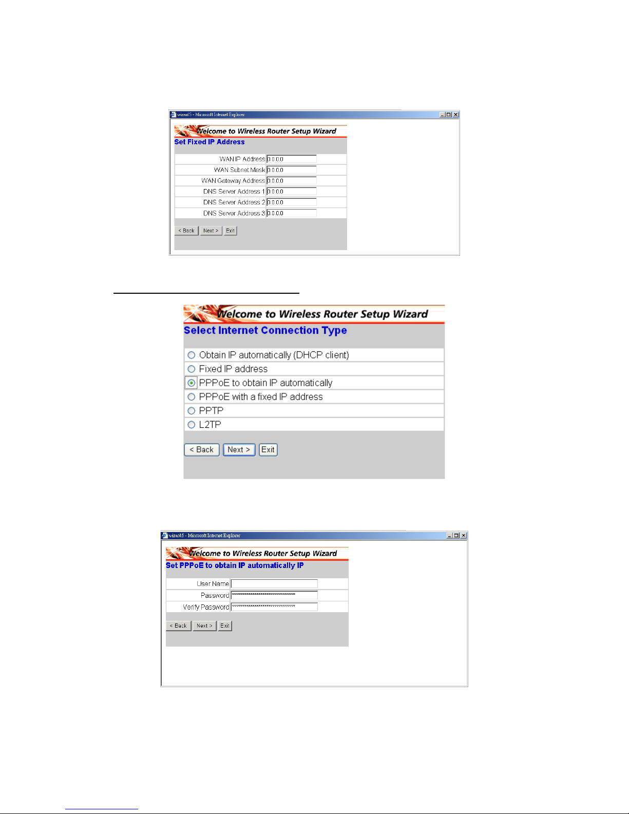
若已指定固定IP位址,會顯示以下的彈出式畫面。 請設定無線網路位址和DNS
伺服器。
PPPoE to obtain IP automatically:
若已使用 PPPoP(撥接式數據機)連接網際網路,網路業者將會提供一組密碼和
使用者名稱並使用 PPPoE。 選擇此選項並輸入必要的資訊。
Page 84
81
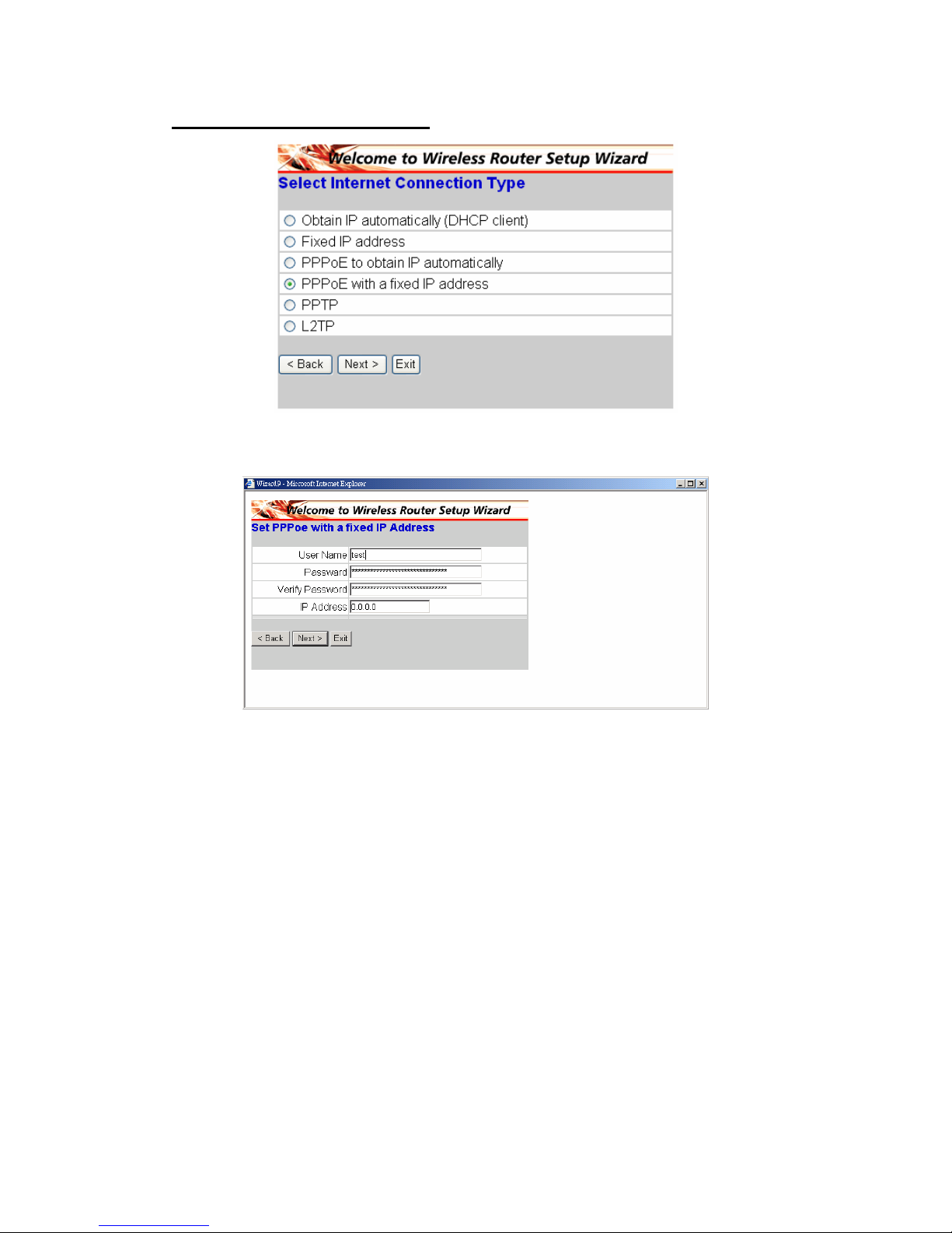
PPPoE with a fixed IP address:
若已使用PPPoE(撥接式數據機)連接網際網路,網路業者將會提供一組密碼、使
用者名稱和IP位址,此時請選擇此選項並輸入必要的資訊。
Page 85
82
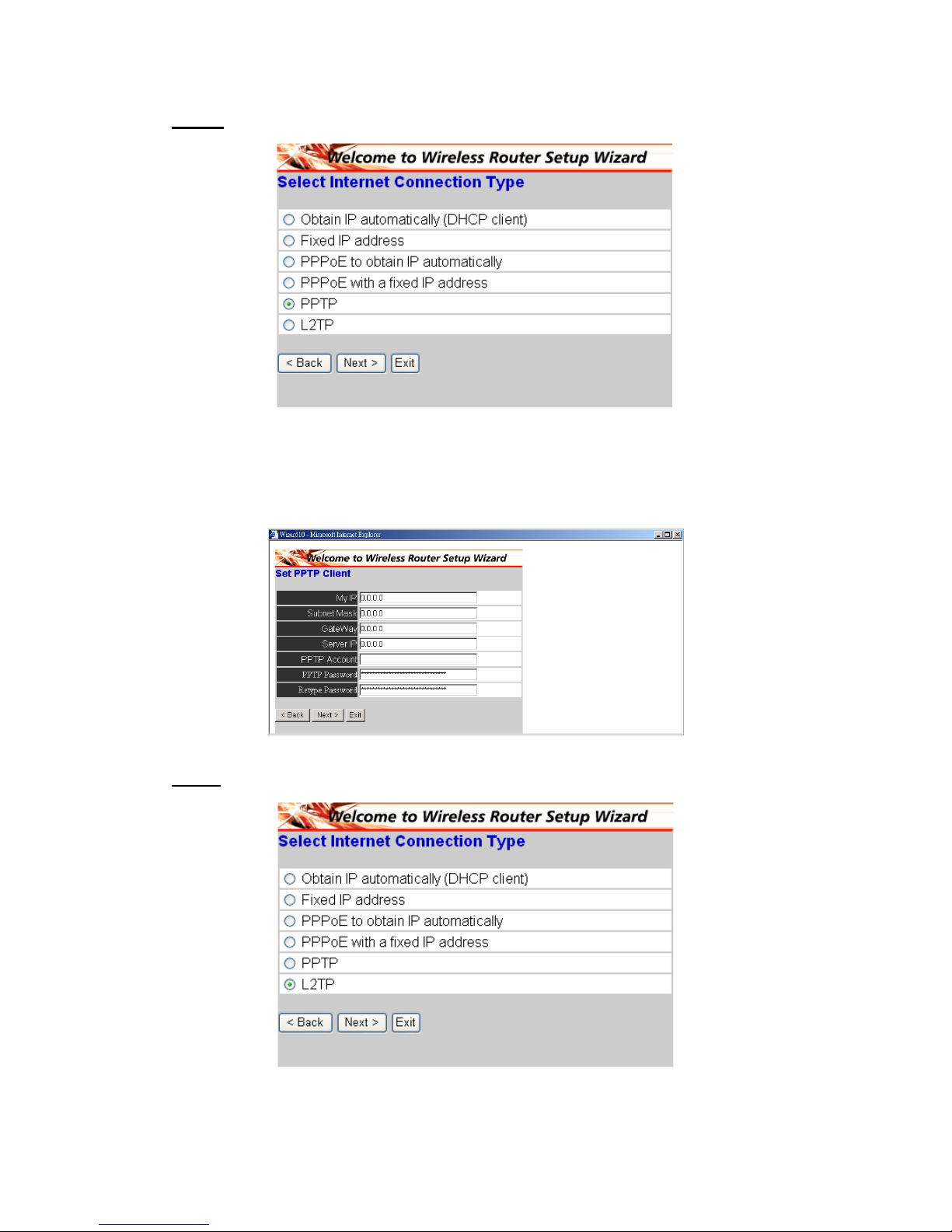
PPTP:
若已使用(PPTP)Xdsl數據機連接網際網路,請輸入您的IP位址、網路遮罩、匣
道、伺服器IP、PPTP帳號和密碼,並在適當欄位填入業者要求您填入的子網路
遮罩。 若網路業者已提供一組連線識別身分ID,請在連線ID欄位內輸入該資訊,
或選擇完全不填。
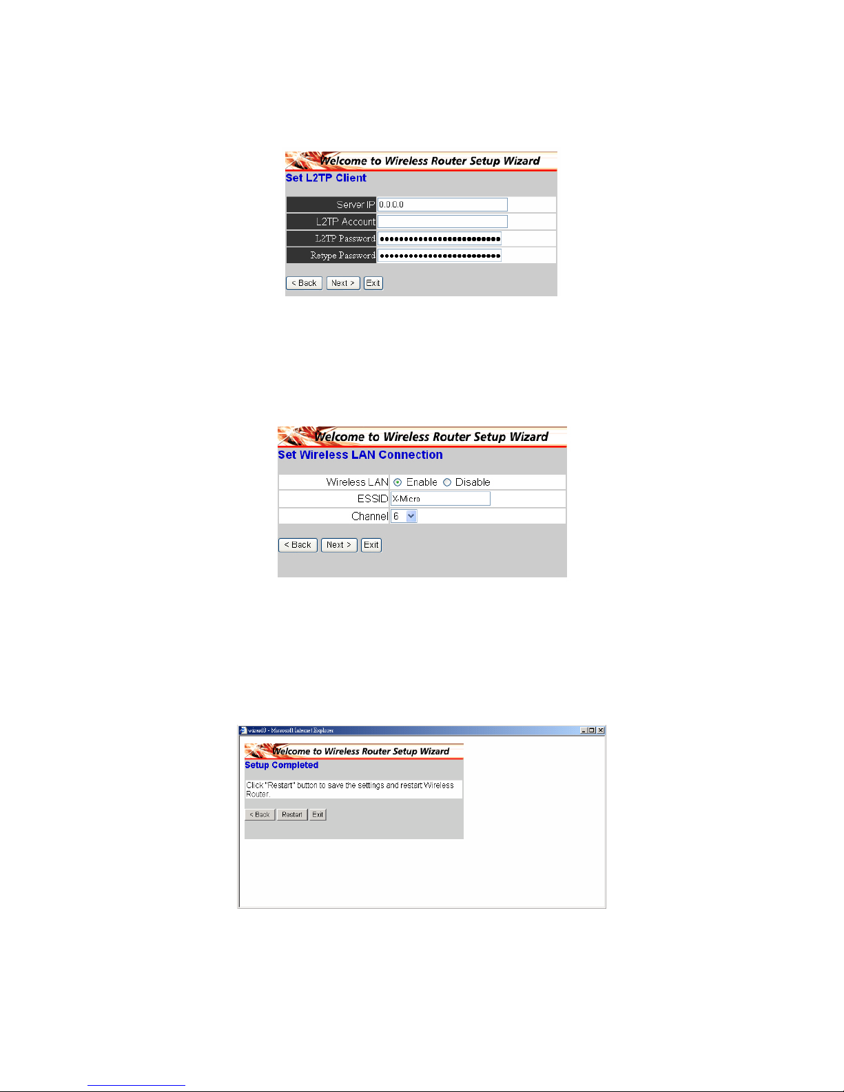
L2TP:
Page 86
83
若已使用L2TP(撥接xDSL)數據機連接網際網路,網路業者將會提供一組伺服器
IP。 帳號和密碼。 選擇此選項並輸入必要資訊。
◆ 步驟 5: 設定無線區域網路連線
按一下「enable」,啟用無線區域網路。 若啟用無線區與網路,請在文字框中鍵
入SSID,並選擇通訊管道(Channel)。 SSID和Channel必須與將連線至路由器
的無線裝置設定相同。
◆ 步驟 6: 重新啟動
設定精靈(Setup wizard)現已完成設定。 新的設定將會在無線路由器重新啟動後
生效。 請按一下「Restart」重新啟動路由器。 若不想進行任何變更,請按一
下「Exit」,保持原設定後並退出。 您也可以按一下「Back」,以便返回變更
設定。
Page 87

www.x-micro.com
 Loading...