

Page 1

WLAN 11g Broadband Router
User Manual
Page 2
This product is in compliance with the essential
requirements and other relevant provisions of the
R&TTE directive 1999/5/EC.
Product Name: X-Micro WLAN 11g Broadband Router
Model Name : XWL-11GRAG
MAX. OUT POWER
COUNTRY CHANNELS
INDOOR OUTDOOR
Spain
2400-2483.5 MHz 1-13 < 100 mW EIRP < 100 mW EIRP
France
2400-2454 MHz 1-8 < 100 mW EIRP < 100 mW EIRP
France
2454-2483.5 MHz 9-13 < 100 mW EIRP < 10 mW EIRP
Italy
2400-2483.5 MHz 1-13 < 100 mW EIRP < 100 mW EIRP
UK
2400-2483.5 MHz 1-13 < 100 mW EIRP < 100 mW EIRP
Netherlands
2400-2483.5 MHz 1-13 < 100 mW EIRP < 100 mW EIRP
Germany
2400-2483.5 MHz 1-13 < 100 mW EIRP < 100 mW EIRP
Austria
2400-2483.5 MHz 1-13 < 100 mW EIRP < 100 mW EIRP
Belgium
2400-2483.5 MHz 1-13 < 100 mW EIRP < 100 mW EIRP
Switzerland
2400-2483.5 MHz 1-13 < 100 mW EIRP < 100 mW EIRP
Luxemburg
2400-2483.5 MHz 1-13 < 100 mW EIRP < 100 mW EIRP
Ireland
2400-2483.5 MHz 1-13 < 100 mW EIRP < 100 mW EIRP
Portugal
2400-2483.5 MHz 1-13 < 100 mW EIRP < 100 mW EIRP
Norway
2400-2483.5 MHz 1-13 < 100 mW EIRP < 100 mW EIRP
Denmark
2400-2483.5 MHz 1-13 < 100 mW EIRP < 100 mW EIRP
Finland
2400-2483.5 MHz 1-13 < 100 mW EIRP < 100 mW EIRP
Iceland
2400-2483.5 MHz 1-13 < 100 mW EIRP < 100 mW EIRP
Greece
2400-2483.5 MHz 1-13 < 100 mW EIRP < 100 mW EIRP
Lichtenstein
2400-2483.5 MHz 1-13 < 100 mW EIRP < 100 mW EIRP
Sweden
2400-2483.5 MHz 1-13 < 100 mW EIRP < 100 mW EIRP
2
Page 3

FCC INFORMATION
FCC Radiation Exposure Statement
This equipment complies with FCC radiation exposure limits set forth for an
uncontrolled environment.
This equipment should be installed and operated with minimum distance
20cm between the radiator & your body.
This transmitter must not be co-located or operating in conjunction with any
other antenna or transmitter.
The equipment has been tested and found to comply with the limits for a
Class B Digital Device, pursuant to part 15 of the FCC Rules. These limits are
designed to provide reasonable protection against harmful interference in a
residential installation.
This equipment generates, uses and can radiate radio frequency energy
and, if not installed and used in accordance with the instruction, may cause
harmful interference to radio communication. However, there is no grantee that
interference will not occur in a particular installation. If th is equipment dose
cause harmful interference to radio or television reception, which can be
determined by turning the equipment off and on, the user is encouraged to try to
correct the interference by one or more of the following measures:
--Reorient or relocate the receiving antenna.
--Increase the separation between the equipment and receiver.
--Connect the equipment into an outlet on a circuit different from that to which
the receiver is connected.
--Consult the dealer or an experienced radio/TV technician for help.
Notice: The Part 15 radi o device oper ates on a non- inter ference bas is wi th othe
r
devices operating at this frequency. Any changes or modification not expressly
approved by the party responsible could void the user’s authority to operate the
device.
REGULATORY INFORMATION
X-Micro WLAN 11g Broadband Router must be installed and used in strict
accordance with the instructions. This device complies with the following radio
frequency and safety standards.
USA - Federal Communications Commission (FCC)
This device complies with Part 15 of FCC Rules. Operation is subject to the
following two conditions:
1. This device may not cause harmful interference.
2. This device must accept any interference that may cause undesired
operation.
3
Page 4

Contents
1. Overview................................................................................................................6
1.1 Product Feature..........................................................................................6
1.2 System Requirements.................................................................................6
1.3 Applications...............................................................................................6
2. Getting Start...........................................................................................................7
2.1 Know the X-Micro WLAN 11g Broadband Router...................................7
2.2 Connect to the X-Micro WLAN 11g Broadband Router...........................8
2.2.1 Access the Setting Menu................................................................8
2.2.2 Quick Setup with Wizard.............................................................10
3. Configuration.......................................................................................................18
3.1 LAN Setting.............................................................................................18
3.1.1 LAN & DHCP Server..................................................................18
3.1.2 WAN ............................................................................................19
3.1.3 Password......................................................................................20
3.1.4 Time .............................................................................................21
3.1.5 Dynamic DNS..............................................................................22
3.2 Wireless....................................................................................................23
3.2.1 Basic.............................................................................................23
3.2.2 Authentication..............................................................................24
3.2.3 Advanced .....................................................................................26
3.3 Status........................................................................................................27
3.3.1 Device Information......................................................................27
3.3.2 Log...............................................................................................28
3.3.3 Log Setting...................................................................................30
3.3.4 Statistic.........................................................................................31
3.3.5 Wireless........................................................................................32
3.4 Routing.....................................................................................................29
3.4.1 Static ............................................................................................29
3.4.2 Dynamic.......................................................................................34
3.4.3 Routing T able...............................................................................35
3.5 Access......................................................................................................35
3.5.1 Filters ...........................................................................................36
3.5.2 Virtual Server...............................................................................41
3.5.3 Special AP....................................................................................42
3.5.4 DMZ.............................................................................................39
3.5.5 Firewall Rule................................................................................44
4
Page 5

3.6 Management.............................................................................................46
3.6.1 SNMP...........................................................................................46
3.6.2 Remote Management...................................................................47
3.7 Tools.........................................................................................................48
3.7.1 Restart..........................................................................................48
3.7.2 Settings.........................................................................................49
3.7.3 Firmware......................................................................................50
3.7.4 Ping T est.......................................................................................51
4. Glossary ...............................................................................................................51
5
Page 6

1. Overview
1.1 Product Feature
● Compliance with IEEE 802.11g and 802.11b standards
● Highly efficient design mechanism to provide unbeatable performance
● Strong network security with WEP and 802.1X encryption
● Achieving data rate up to 108Mbps for 802.11g and 11Mps for 802.11b with
wide range coverage; high performance to deliver up to 108Mbps raw data rate
for 802.11g
● Quick and easy setup with Web-based management utility
1.2 System Requirements
● Windows 98, 98SE, Millennium Edition (ME), 2000 and XP operating systems
● Microsoft Internet Explorer 5.5 or higher
● DSL/ Cable Modem Broadband Internet connection and ISP account
● PCs equipped with 10Mbps or 10/100 Mbps Ethernet connection to support
TCP/IP protocol
● One CD-ROM drive
1.3 Applications
● Home SOHO networking for device sharing and wireless multimedia
● Wireless office provides a wider range for home and SOHO Ethernet
● Enables wireless building-to-building data communication
● Built-in infrastructure mode
● Router provides ideal solution for:
● Difficult-to-wire environments
● Temporary LANs for scenarios such as trade-exhibitions and meetings
● Enables LAN adaptability to frequently changing environments
● Enables remote access to corporate network information, for example e-mail and
the company home page
6
Page 7
2. Getting Start
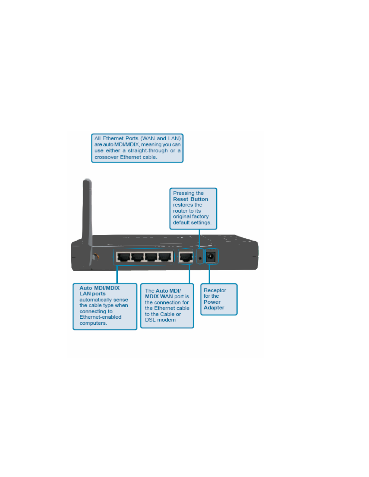
2.1 Know the X-Micro WLAN 11g Broadband Router
Ports:
7
Page 8
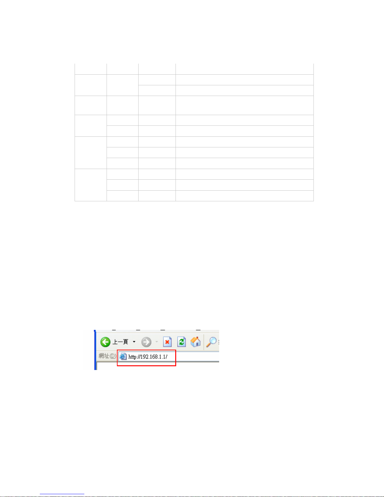
LEDs:
LED Color Status Description
On Indicates proper connection to power supply.
Power
Green
OFF The unit is not receiving power
Status
Green On
Indicates that the device is
connected to the WLAN.
On Indicates connection to the WAN port
WAN
Blinking Data transmission.
On Link is established
On Blinking Packet transmit or receive activity
WLAN
Off — No Link activity
On Indicates connection is established.
On Blinking Data transmissions
LAN
Off — No LAN connections
2.2 Connect to the X-Micro WLAN 11g Broadband Router
2.2.1 Access the Setting Menu
You could start to access the configuration menu anytime by opening a web browser
window by typing the IP address of this wireless router. The default IP is
192.168.1.1.
The below window will popup. Please enter the user name and password. Both of
the default is “admin”.
8
Page 9
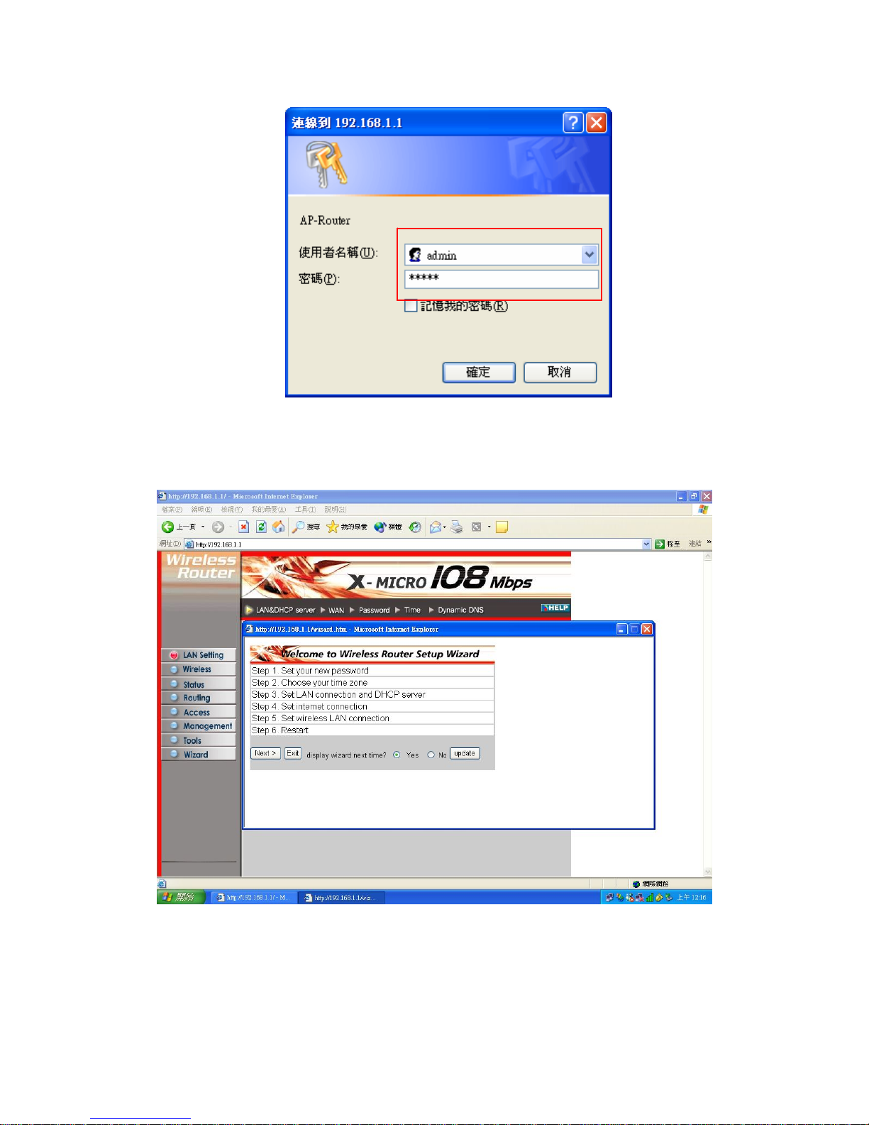
Now, the main menu screen is popup.
9
Page 10
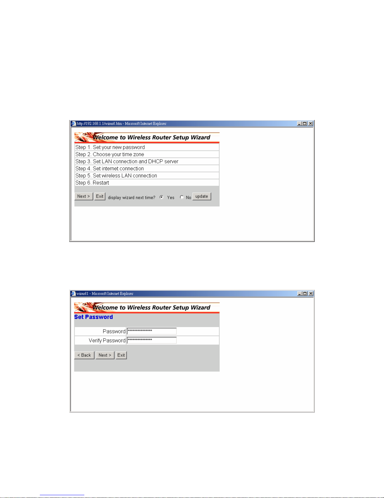
2.2.2 Quick Setup with Wizard
Setup wizard is provided as the part of the web configuration utility. You can simply
follow the step-by-step process to get your wireless router configuration ready to run
in 6 easy steps by clicking on the “Wizard” button on the function menu. The
following screen will appear. Please click “Next” to continue.
Step 1: Set your new Password
You can change the password as you like and then click “Next” to continue.
10
Page 11
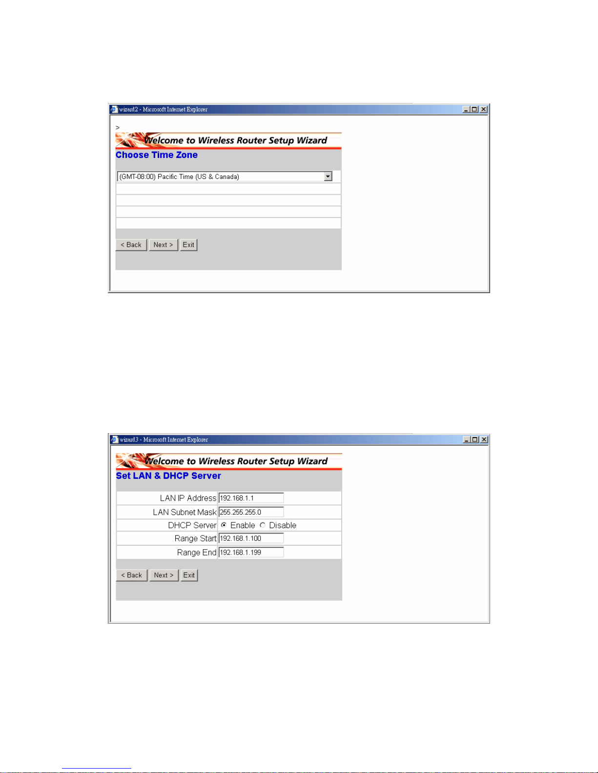
Step2: Choose your time zone
Select your time zone from the drop down list. Please click “Next” to continue.
Step 3: Set LAN connection and DHCP server
Set your IP address and mask. The default IP is 192.168.1.1. If you like to enable
DHCP, please click “Enabled”. DHCP enabled is able to automatically assign IP
addresses. Please assign the range of IP addresses in the fields of “Range start” and
Range end”. Please click “Next” to continue.
“
11
Page 12
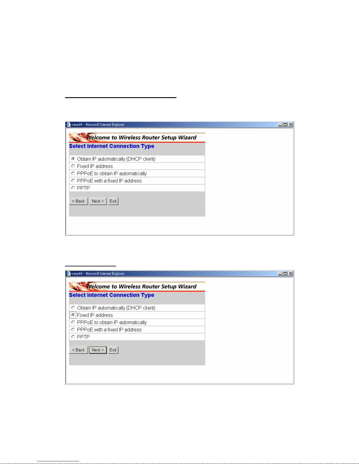
Step 4: Set Internet connection
Select how the router will set up the Internet connection: Obtained IP automatically;
Fixed IP address; PPPoE to obtain IP automatically; PPPoE with a fixed IP address;
PPTP.
Obtain IP automatically (DHCP client):
If you have enabled DHCP server, choose "Obtain IP automatically (DH CP client)" to
have the router assign IP addresses automatically.
Fixed IP Address:
If Fixed IP address is assigned, the below screen will pop up. Please set the WAN
12
Page 13
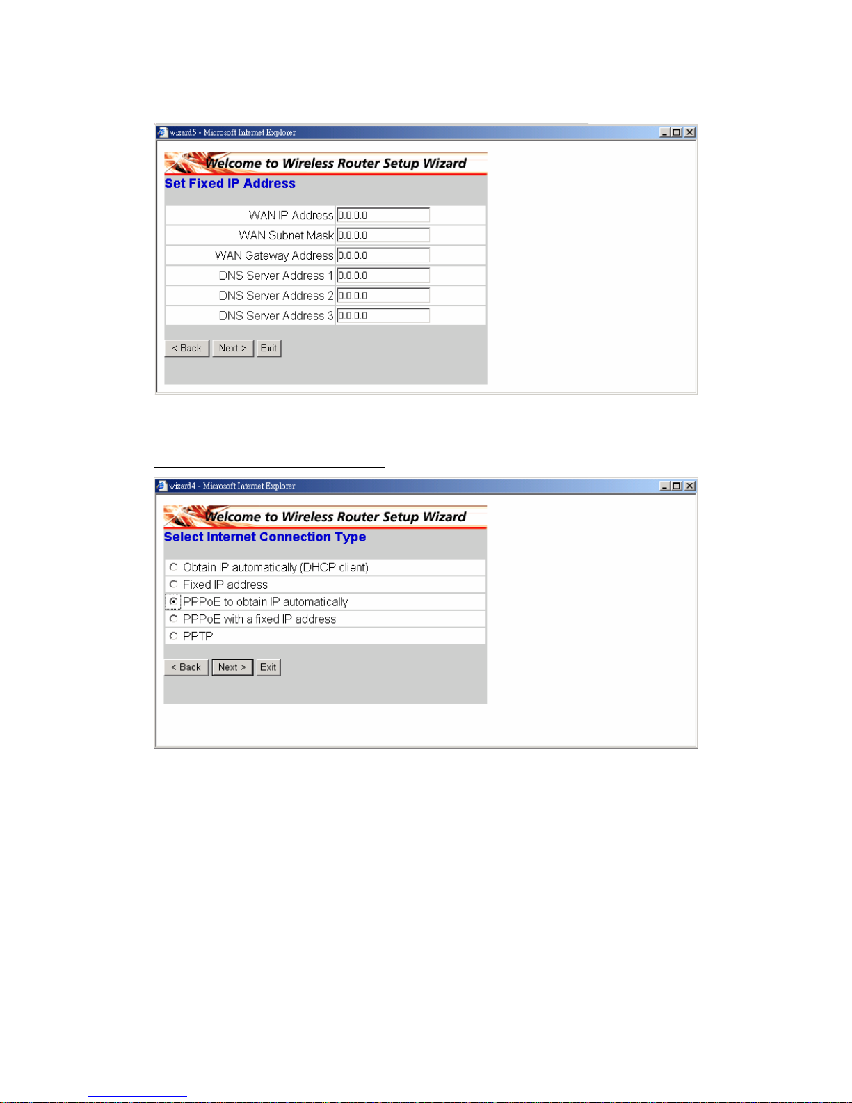
address and DNS server.
PPPoE to obtain IP automatically:
13
Page 14
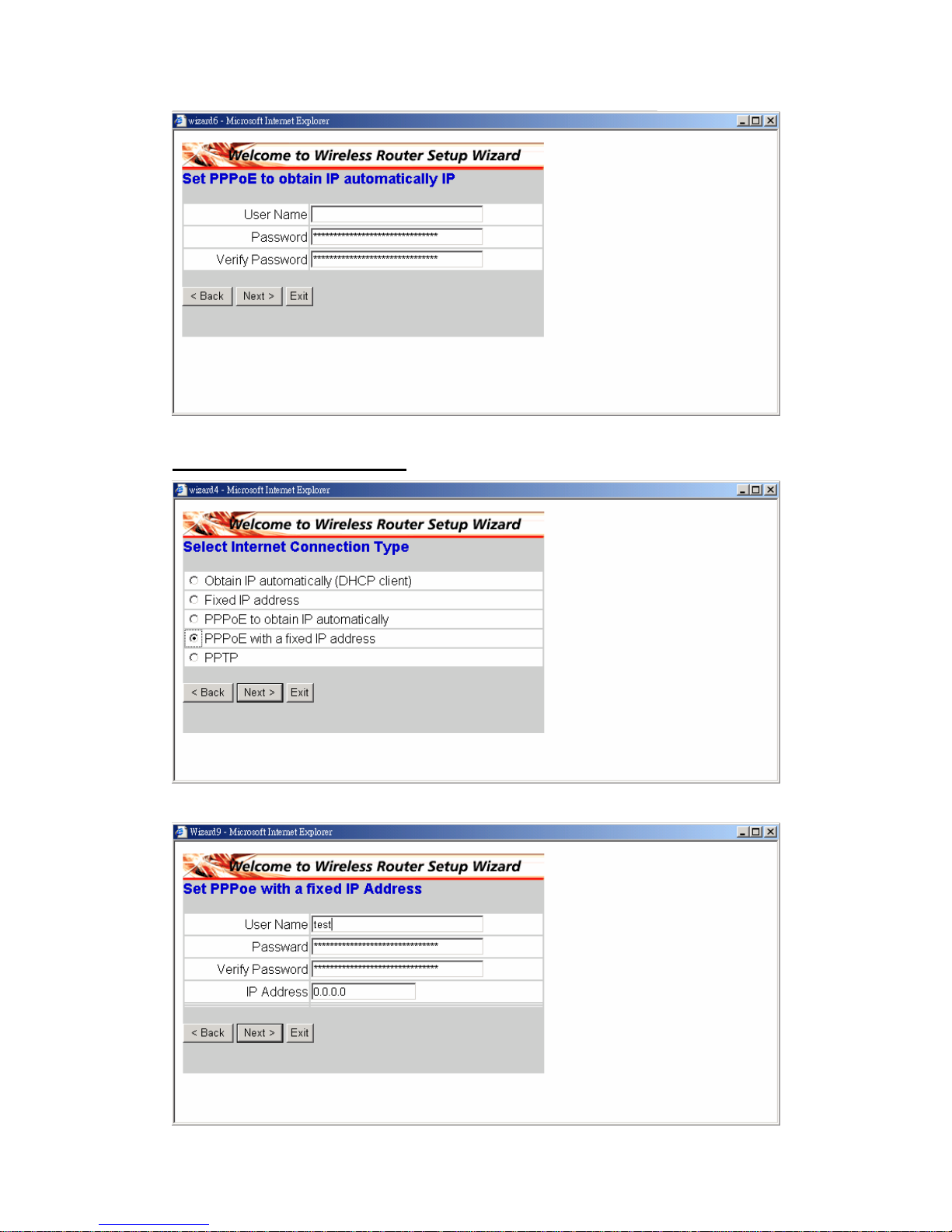
PPPoE with a fixed IP address:
14
Page 15

15
Page 16
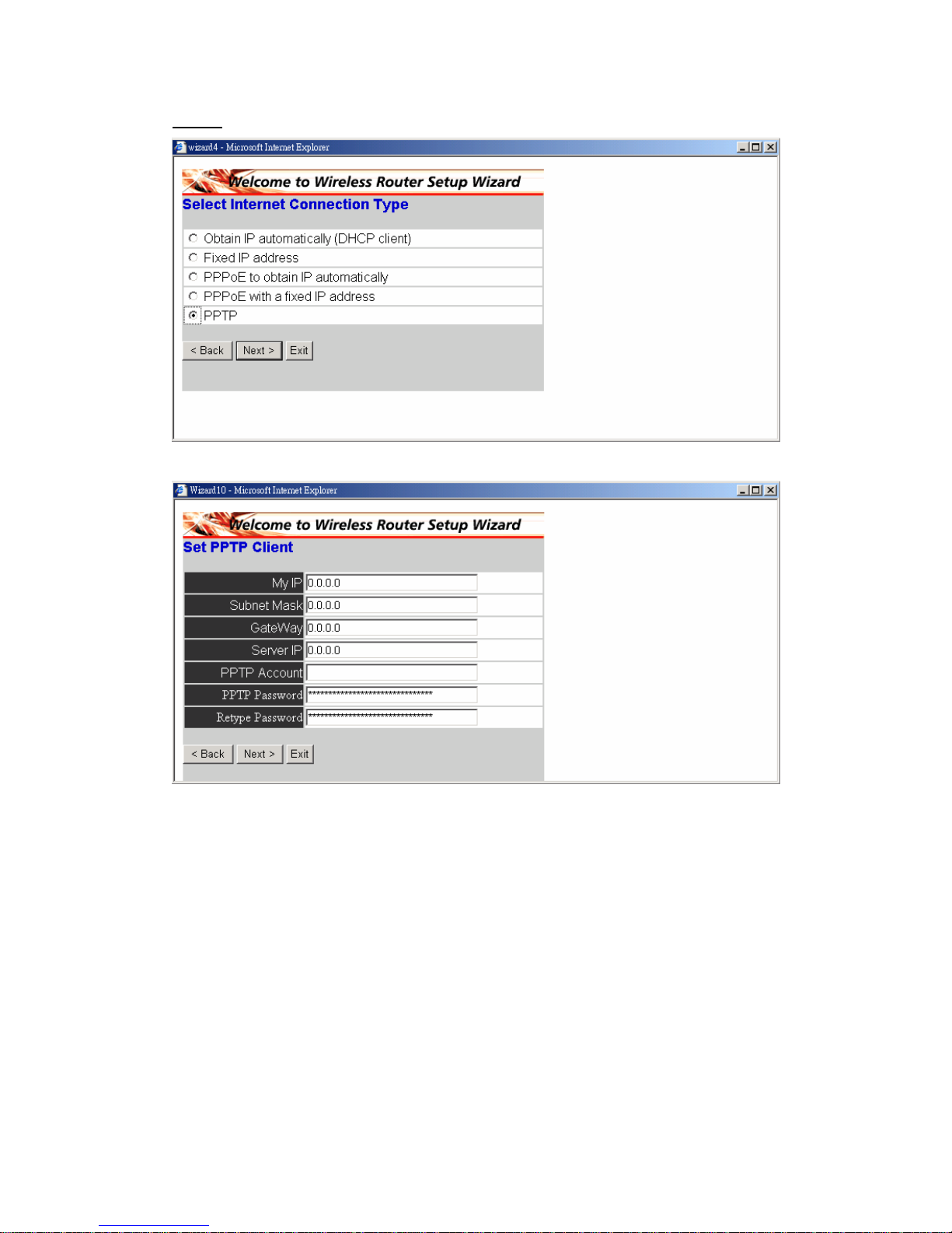
PPTP:
16
Page 17
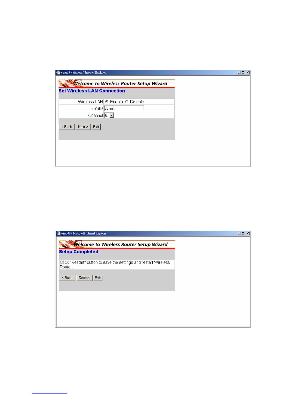
Step 5: Set Wireless LAN connection
LAN. If you enable the wireless LAN, type the
communications channel. The SSID and channel
must be the same as wireless devices attempting communication to the router.
Click “enable” to enable wireless
SSID in the text box and select a
Step 6: Restart
The Setup wizard is now completed. The new settings will be effective after the
Wireless router restarted. Please click “Restart” to reboot the router. If you do not
want to make any changes, please click “Exit” to quit without any changes. You
also can go back to modify the setting by clicking “Back”.
17
Page 18
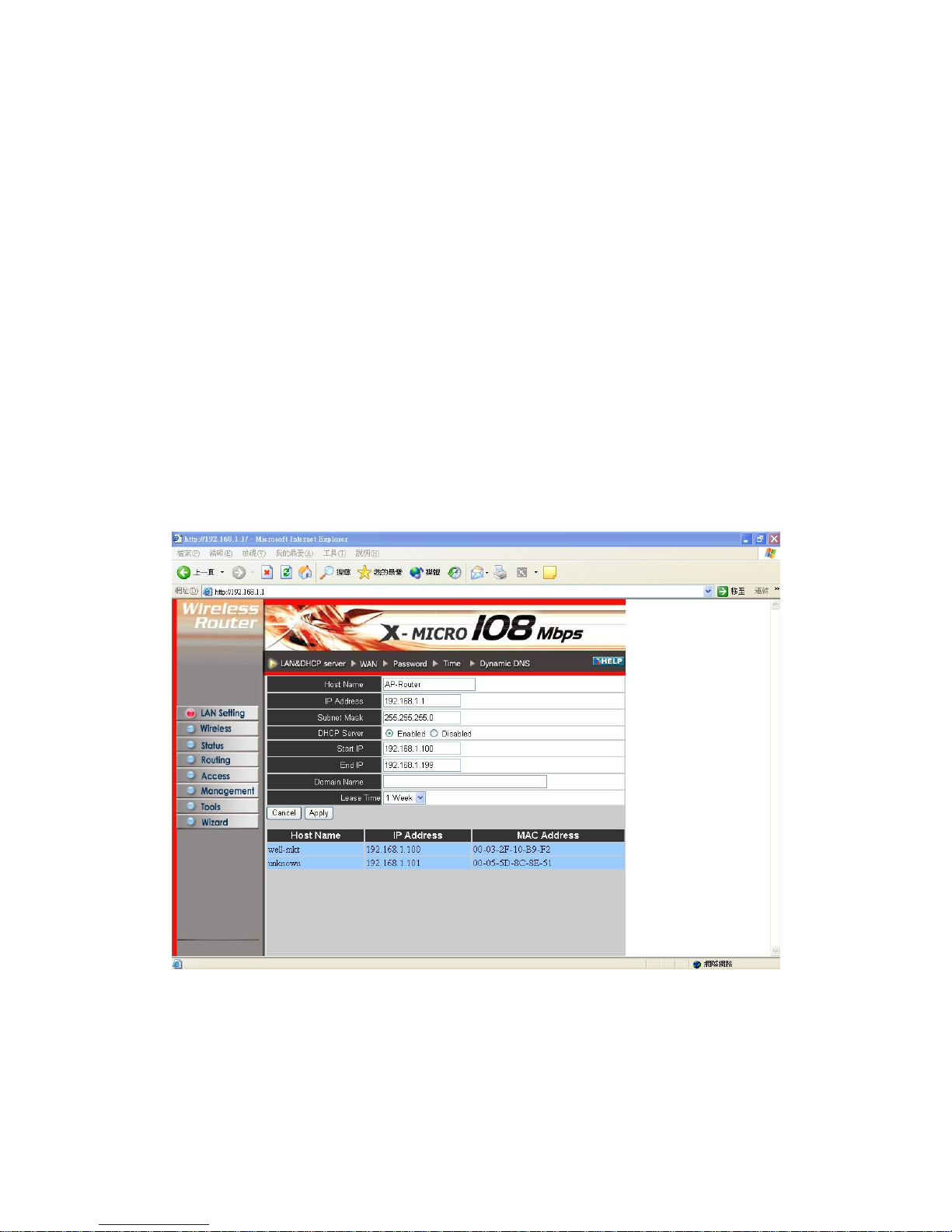
3. Configuration
3.1 LAN Setting
The screen enables you to configure the LAN & DHCP Server, set WAN parameters,
S.
3.1.1 LAN & DHCP Server
This page enables you to set LAN and DHCP properties, such as the host name, IP
create Administrator and User passwords, and set the local time, time zone, and
dynamic DN
address, subnet mask, and domain name. LAN and DHCP profiles are listed in the
DHCP table at the bottom of the screen.
Host Name: Type the host name in the text box. The host name is required by some
address of the router. The default IP address is 192.168.1.1.
ISPs. The default host name is "AP-Router."
IP Addr ess: This is the IP
Subnet Mask: Type the subnet mask for the router in the text box. The default subnet
mask is 255.255.255.0.
18
Page 19
DHCP Server: Enables the DHCP server to allow the router to automatically assign
IP addresses to de vices connecting to the LAN. DHCP is enabled by default.
address, and MAC address of the client.
to
all LAN devices connected to the router.
N devices connected to the router.
omain Name: Type the local domain name of the network in the text box. This item
is optional.
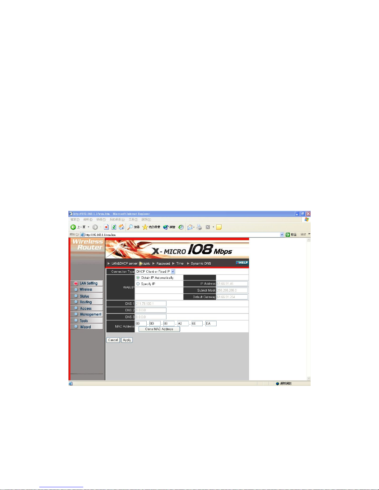
his screen enables you to set up the router WAN connection, specify the IP address
for the WAN, add DNS numbers, and enter the MAC address.
All DHCP client computers are listed in the table at the botto m of the screen,
providing the host name, IP
Start IP: Type an IP address to serve as the start of the IP range that DHCP will use
assign IP addresses to
End IP: Type an IP address to serve as the end of the IP range that DHCP will use to
assign IP addresses to all LA
D
3.1.2 WAN
T
Connection T ype: Select the connection type, either DHCP client, Fixed IP or PPPoE
from the drop-down list.
WAN IP: Select whether you want to specify an IP address manually, or want DHCP
to obtain an IP address automatically. When Specify IP is selected, type the IP address,
19
Page 20
subnet mask, and default gateway in the text boxes. Your ISP will provide you with
DNS 1/2/3: Type up to three DNS numbers in the text boxes. Your ISP will provide
address of the router WAN
interface in this field.
DNS 1/2/3: Type up to three DNS numbers in the text boxes. Your ISP will provide
you with this information.
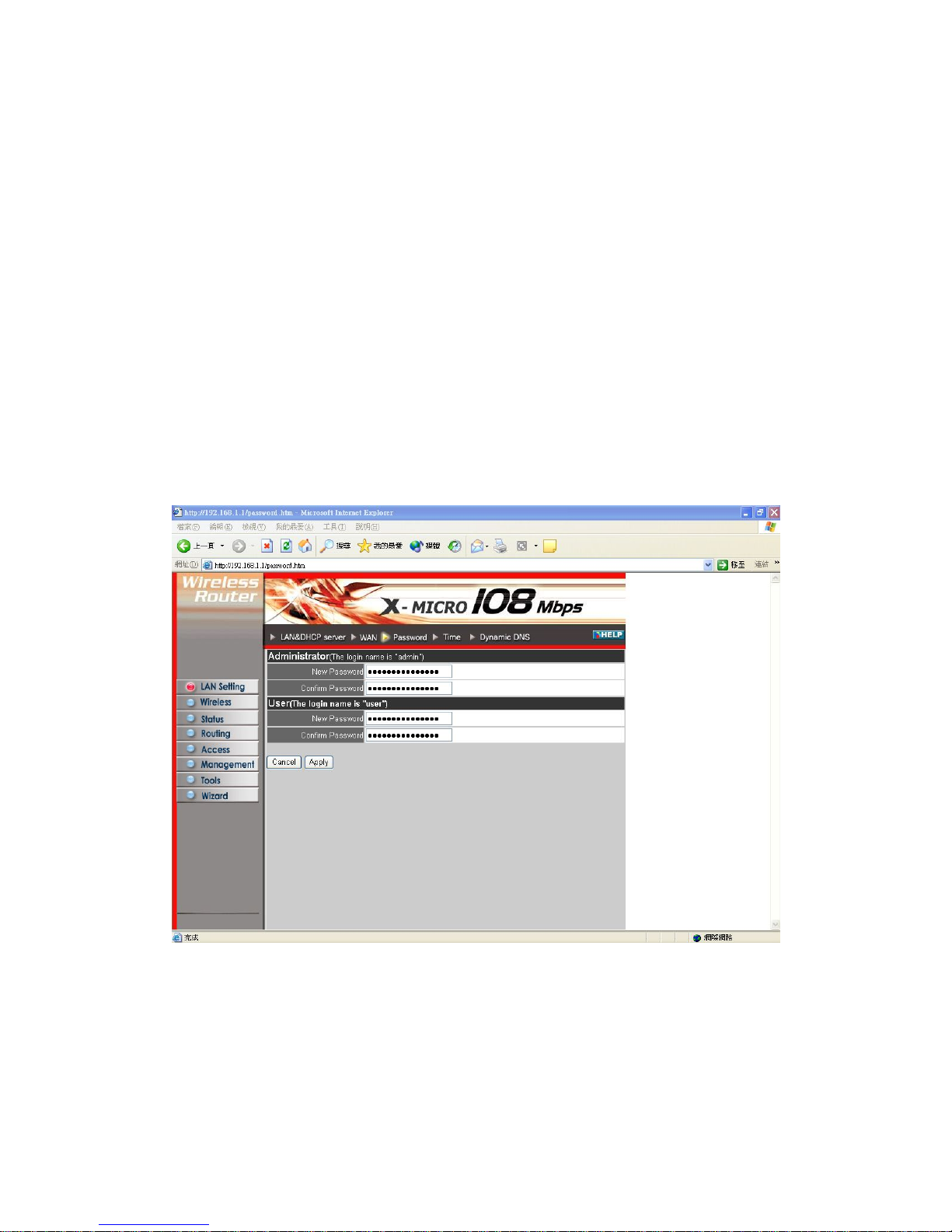
3.1.3 Password
This screen enables you to set administrative and user passwords. These passwords
are used to gain access to the router interface.
this information.
you with this information.
MAC Address: If required by your ISP, type the MAC
Administrator: Type the password the Administrator will use to log in to the system.
The password must be typed again for confirmation.
20
Page 21
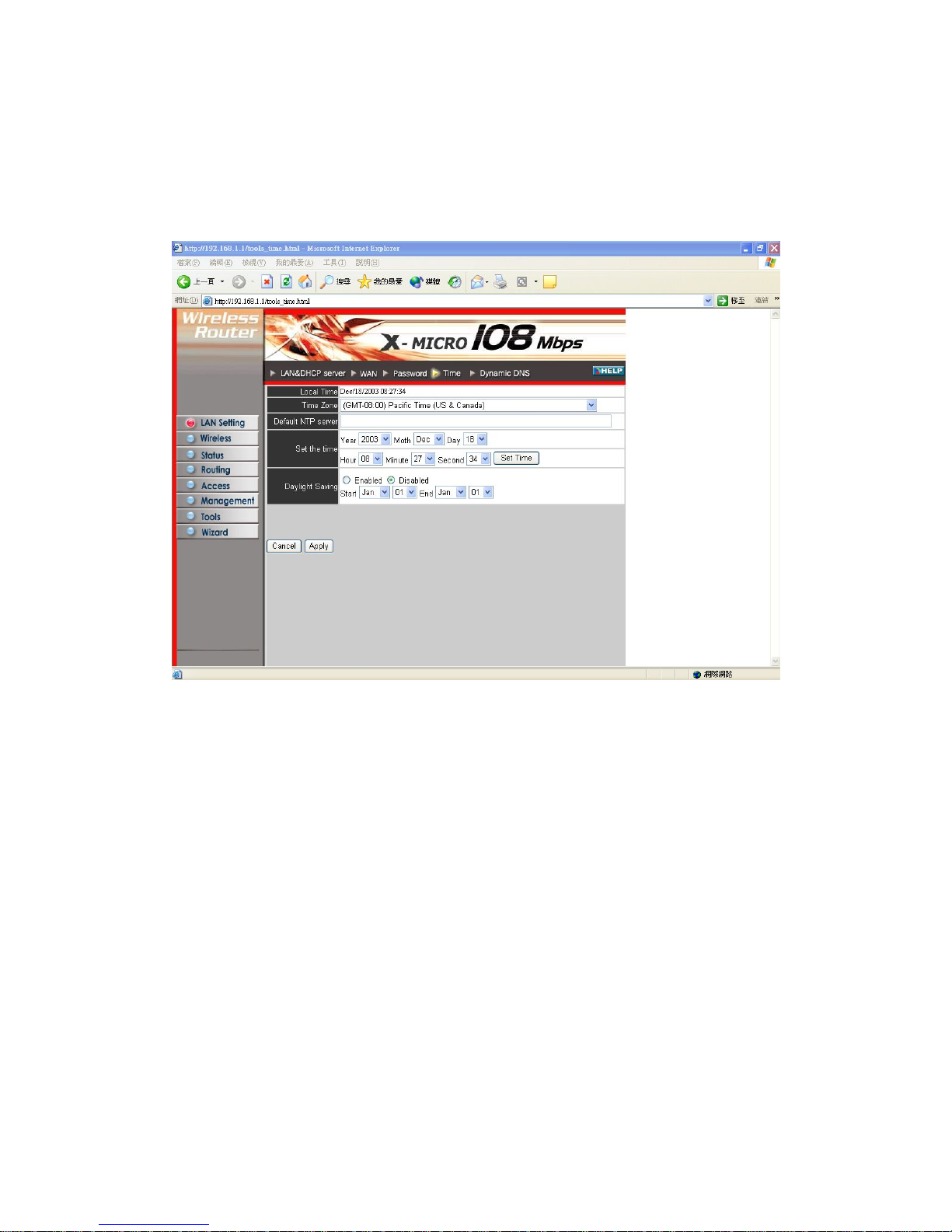
3.1.4 Time
This screen enables you to set the time and date for the router's real-time clock, select
your time zone, and enable or disable daylight saving.
Local Time: Displays the local time and date.
Time Zone: Select your time zone from the drop-down list.
Daylight Saving: Enables you to enable or disable daylight saving time. When
enabled, select the start and end date for daylight saving time.
21
Page 22
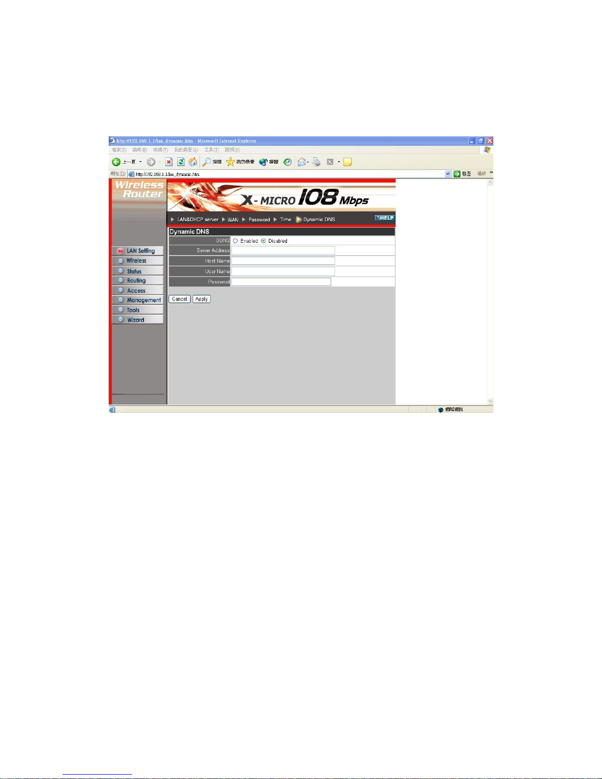
3.1.5 Dynamic DNS
This allows you to set the DNS server.
22
Page 23
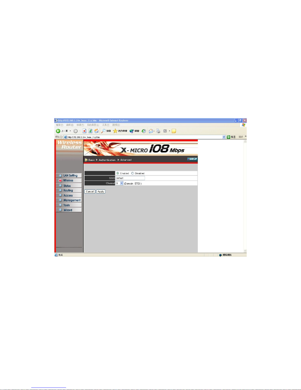
3.2 Wireless
This section enables you to set wireless communications parameters for the router's
This page allow you to enable and disable the wireless LAN function, create a SSID,
and select the channel for wireless communications.
wireless LAN feature.
3.2.1 Basic
Enable/Disable: Enables and disables wireless LAN via the router.
SSID: Type an SSID in the text box. The SSID of any wireless device must mat
SSID typed here in order for the wireless device to access the LAN and WAN via the
router.
ch the
hannel: Select a transmission channel for wireless communications. The channel of
any wireless device must match the channel selected here in order for the wireless
device to access the LAN and WAN via the router.
C
23
Page 24
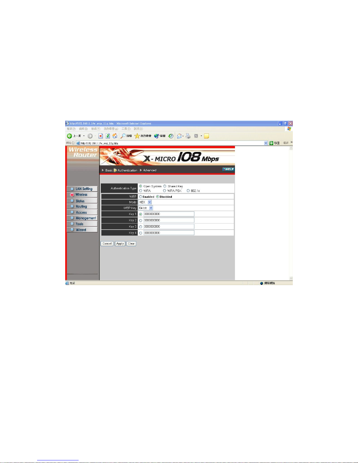
3.2.2 Authentication
This screen enables you to set authentication type for secure wireless communications.
Open System allows public access to the router via wireless communications.
Shared Key requires the user to set a WEP key to exchange data with other wireless
clients that have the same WEP key.
Mode: Select the level of encryption you want from the drop-down list. The router
supports, 64- and 128-bit encryption.
WEP Key: Select WEP Key - 64 or 128 bits from the drop-down list.
Key 1 ~ Key 4: Enables you to create an encryption scheme for Wireless LAN
transmissions. Manually enter a set of values for each key. Select which key you want
to use by clicking the radio button next to the key. Click Clear to erase key values.
24
Page 25
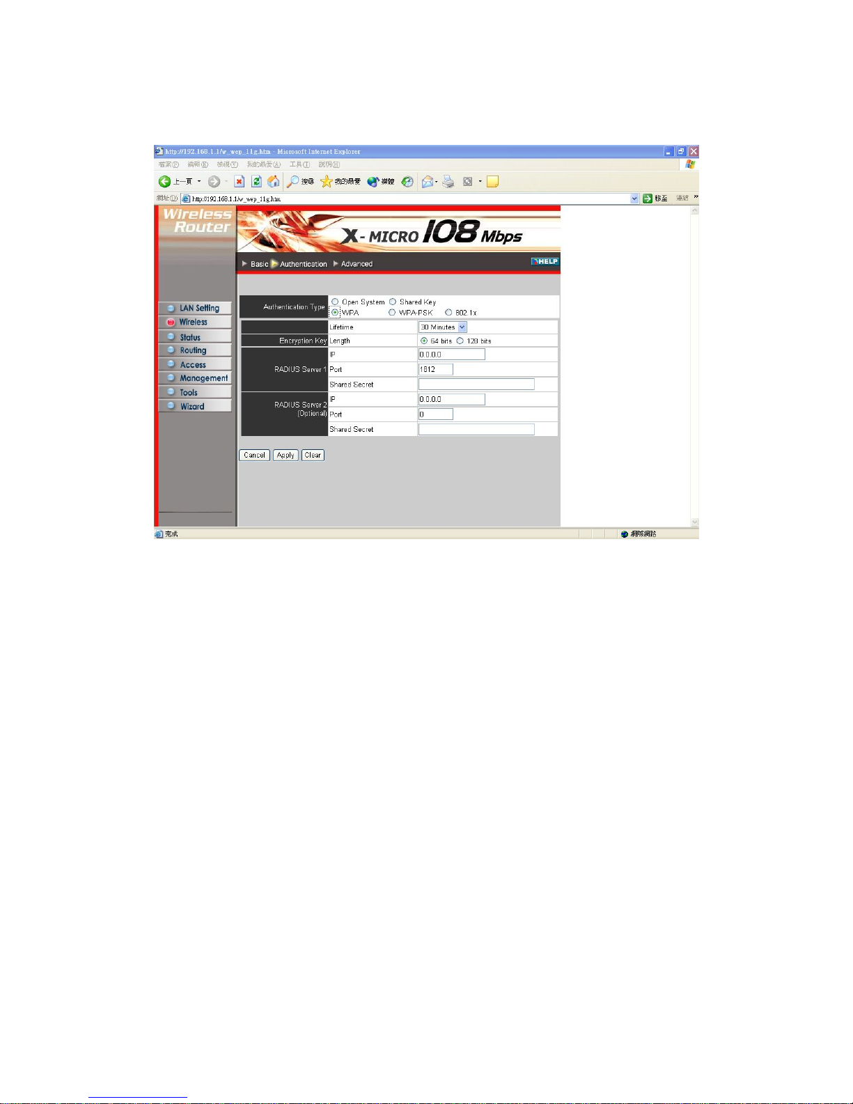
If WPA is selected, please set the parameters for the RADIUS server. This is also
ng. referred to the 802.1X setti
25
Page 26
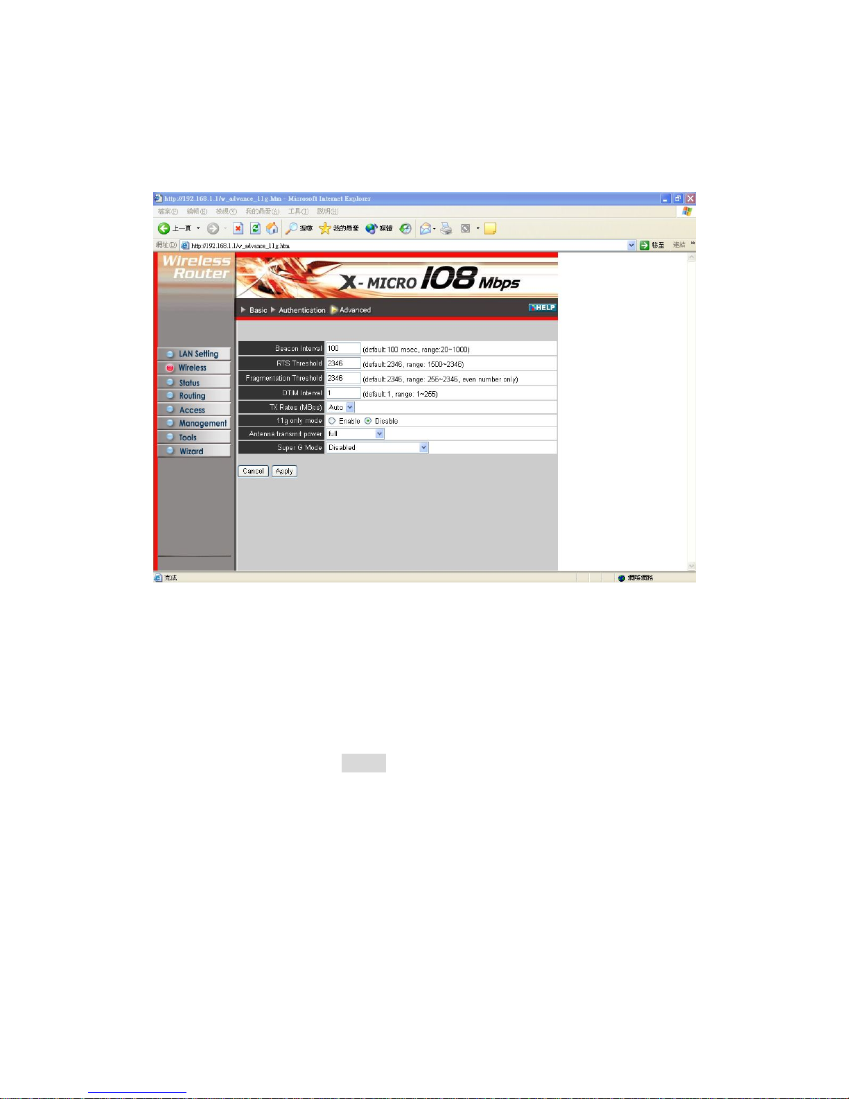
3.2.3 Advanced
This screen enables you to configure advanced wireless functions.
Beacon Interval: Type the beacon interval in the text box. You can specify a value
from 1 to 1000. The default beacon interval is 100.
RTS Threshold: Type the RTS (Request-To-Send) threshold in the text box. This
value stabilizes data flow. If data flow is irregular, choose values between 256 and
2432 until data flow is normalized.
Fragmentation Threshold: Type the fragmentation threshold in the text box. If
packet transfer error rates are high, choose values between 256 and 2432 until packet
transfer rates are minimized. (
NOTE
: set this fragmentation threshold value may
diminish system performance.)
DTIM Interval: Type a DTIM (Delivery Traffic Indication Message) interval in the
text box. You can specify a value between 1 and 65535. The default value is 3.
TX Rates (MBps): Select one of the wireless communications transfer rates,
measured in megabytes per second, based upon the speed of wireless adapters
: Adjust the power of the antenna transmission by selecting
connected to the WLAN.
11g only mode: enable or disable.
Antenna T ransmit Power
from the dropping list.
26
Page 27
Super G mode: Super G mode is disabled by selecting “Disable” from the drop lis
you like to use Super G to enhance the speed, ther
t. If
e are three options on Super G
er G mode without the
G
al’ G.. Static turbo means
es you to view the status of the router LAN, WAN connections,
and view logs and statistics pertaining to connections and packet transfers.
ireless and WAN configuration.
mode: Super G without turbo; Super G with Dynamic turbo and Super G with Static
turbo. Turbo mode indicates the combination of two channels to enhance the
throughput. Super G without turbo indicates that it is on Sup
channel’s combination. Dynamic turbo is able to automatically detect if any ‘Super
based’ product is available. If no, the connection is via ‘norm
it will not go back to ‘normal’ G once it starts.
3.3 Status
This selection enabl
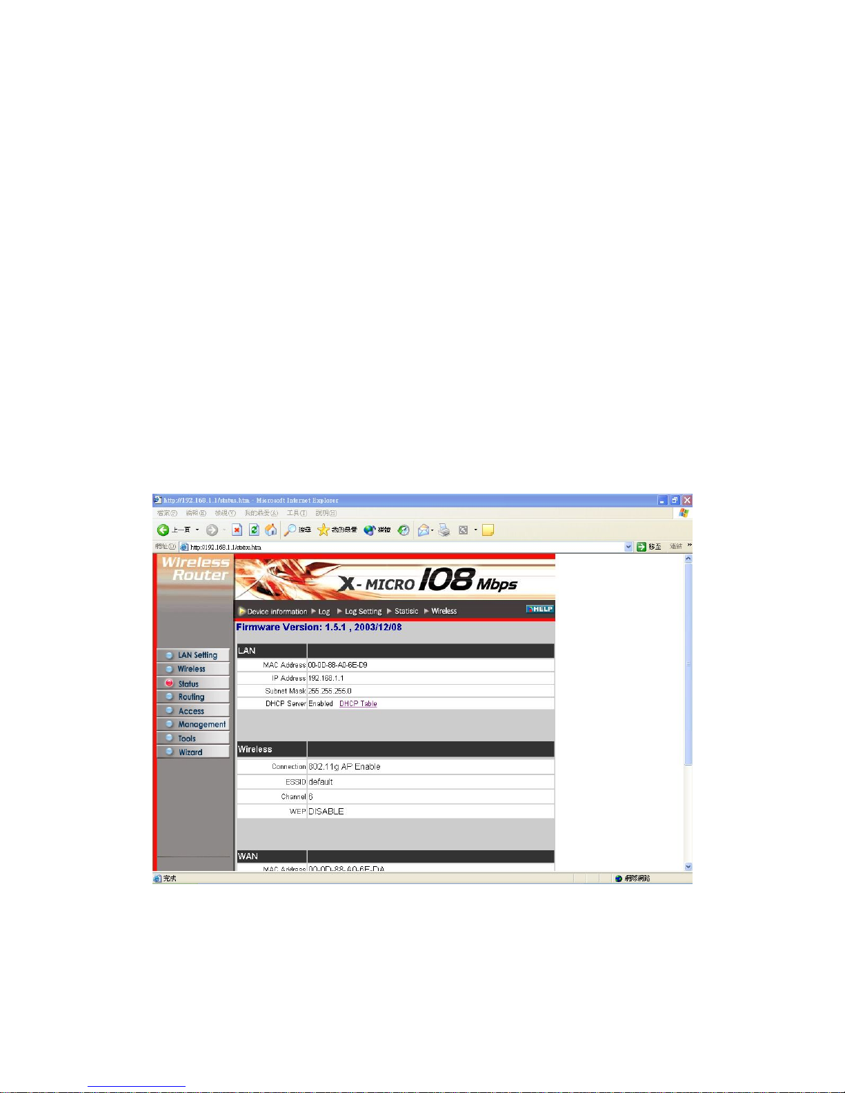
3.3.1 Device Information
This screen enables you to view the router LAN, W
Firmware Version: Displays the latest build of the router firmware interface. After
updating the firmware in Tools - Firmware, check this to ensure that your firmware
was successfully updated.
LAN: This field displays the router's LAN interface MAC address, IP address, subnet
27
Page 28

mask, and DHCP server status. Click DHCP Table to view a list of client stations
currently connected to the router LAN interface.
Wireless: Displays the router's wireless connection information, including the router's
wireless interface MAC address, the connection status, the SSID status, which
channel is being used, and whether WEP is enabled or not.
WAN: This field displays the router's WAN interface MAC address, DHCP client
status, IP address, subnet mask, default gateway, and DNS.
Click DHCP Release to release all IP addresses assigned to client stations connected
to the WAN via the router. Click DHCP Renew to reassign IP addresses to client
stations connected to the WAN.
3.3.2 Log
This screen enables you to view a running log of router system statistics, events, and
activities. The log displays up to 200 entries. Older entries are overwritten by new
entries. The Log screen commands are as follows:
Click First Page to view the first page of the log
ge
t page
ew log
Click Last Page to view the final page of the log
Click Previous Page to view the page just before the current pa
Click Next Page to view the page just after the curren
Click Clear Log to delete the contents of the log and begin a n
Click Refresh to renew log statistics
28
Page 29
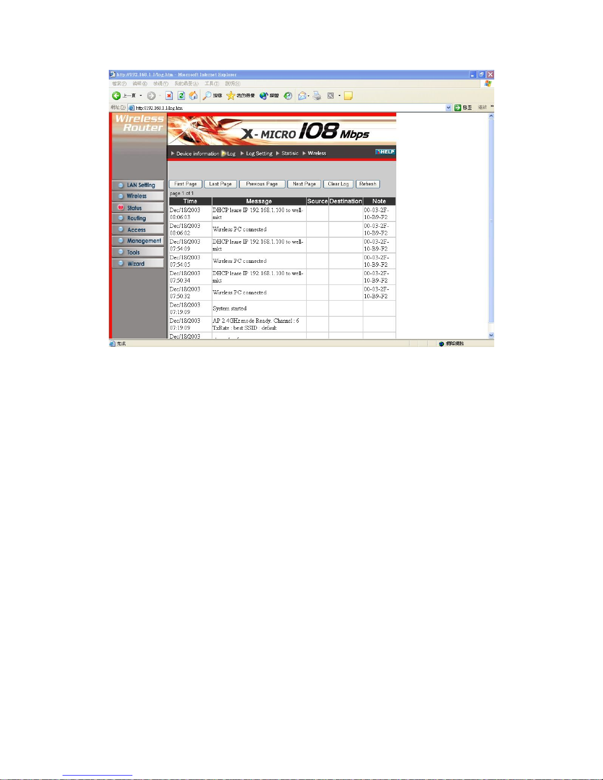
Time: Displays the time and date that the log entry was created.
Message: Displays summary information about the log entry.
Source: Displays the source of the communication.
Destination: Displays the destination of the communication.
Note: Displays the IP address of the communication
29
Page 30
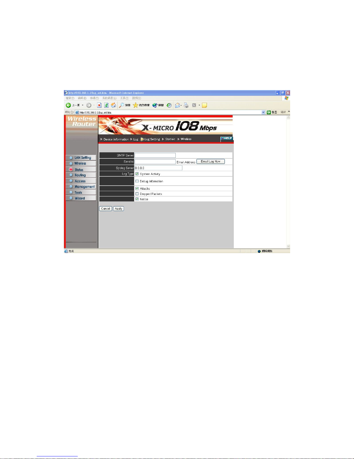
3.3.3 Log Setting
parameters. This screen enables you to set router logging
SMTP Server: Type the SMTP server address for the email that the log will be sent to
in the next field.
Send to: Type an email address for the log to be sent to. Click Email Log Now to
immediately send the current log.
Syslog Server: Type the IP address of the Syslog Server if you want the router to
listen and receive incoming Syslog messages.
Log T ype: Enables you to select what items will be included in the log:
● System Activity: Displays information related to router operation.
● Debug Information: Displays information related to errors and system malfunction.
● Attacks: Displays information about any malicious activity on the network.
● Dropped Packets: Displays information about packets that have not been transferred
successfully.
● Notice: Displays important notices by the system administrator.
30
Page 31
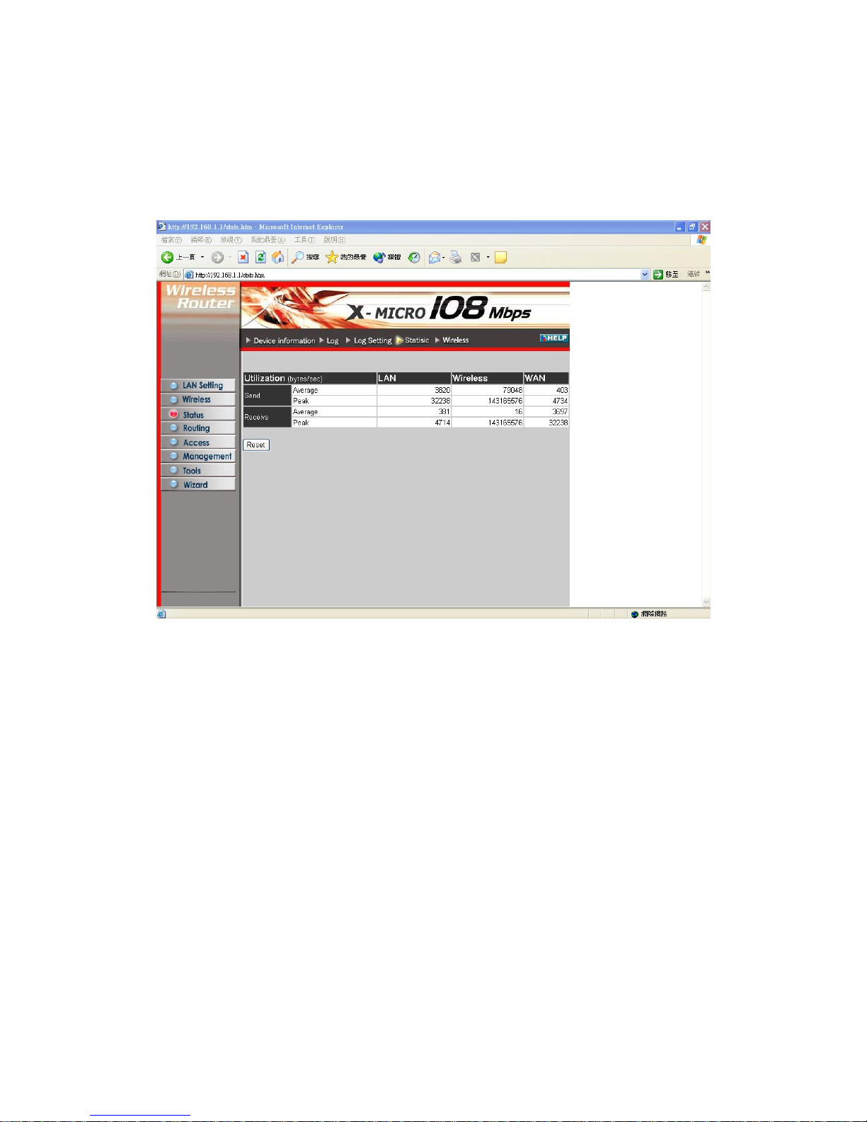
3.3.4 Statistic
This screen displays a table that shows the rate of packet transmission via the router
LAN and WAN ports (in bytes per second).
Click Reset to erase all statistics and begin logging statistics again.
31
Page 32
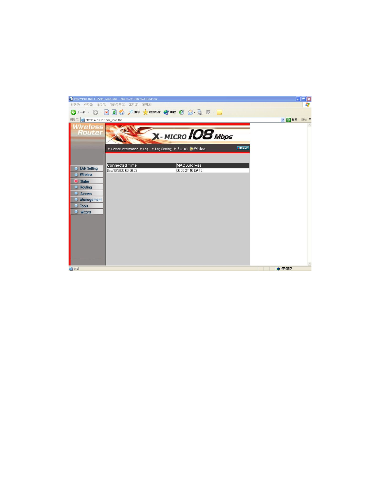
3.3.5 Wireless
d This screen enables you to view information about wireless devices that are connecte
to the wireless router.
Connected Time: Displays how long the wireless device has been connected to the
LAN via the router.
MAC Address: Displays the devices wireless LAN interface MAC address.
32
Page 33
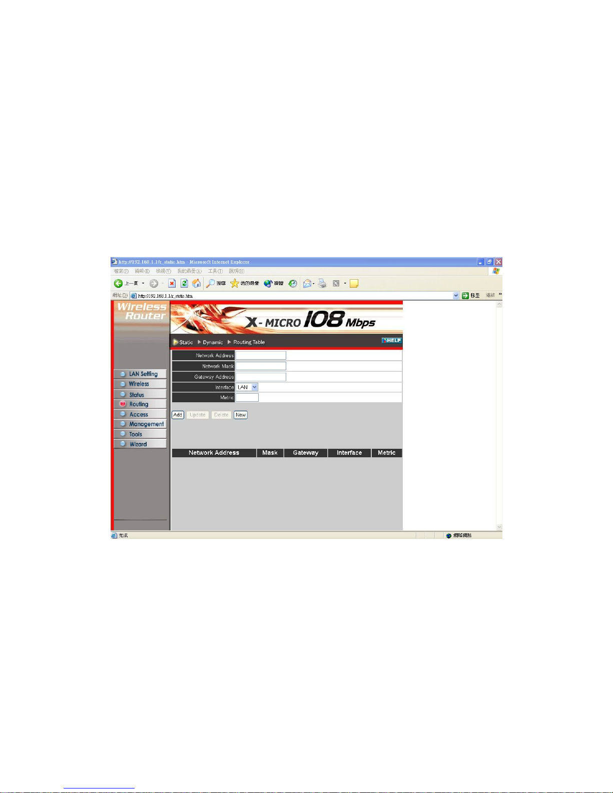
3.4 Routing
This selection enables you to set how the router forwards data: Static and Dynamic.
Routing Table enables you to view the information created by the router that displays
.4.1 Static
eters by which the router forwards data to its destination if
your network has a static IP address.
the network interconnection topology.
3
It enables you to set param
Network Address: Type the static IP address your network uses to access the Internet.
s information.
pe
network mask defaults to 255.255.255.255. Your ISP or network
dress: Type the gateway address for your network. Your ISP or network
administrator provides you with this information.
Interface: Select which interface, WAN or LAN, you use to connect to the Internet.
Metric: Select which metric you want to apply to this configuration.
Add: Click to add the configuration to the static IP address table at the bottom of the
Your ISP or network administrator provides you with thi
Network Mask: Type the network (subnet) mask for your network. If you do not ty
a value here, the
administrator provides you with this information.
Gateway Ad
33
Page 34
page.
s in the static IP address table at the bottom of the
page and, after changing parameters, click Update to confirm the changes.
New: Click New to clear the text boxes and add required information to create a new
entry.
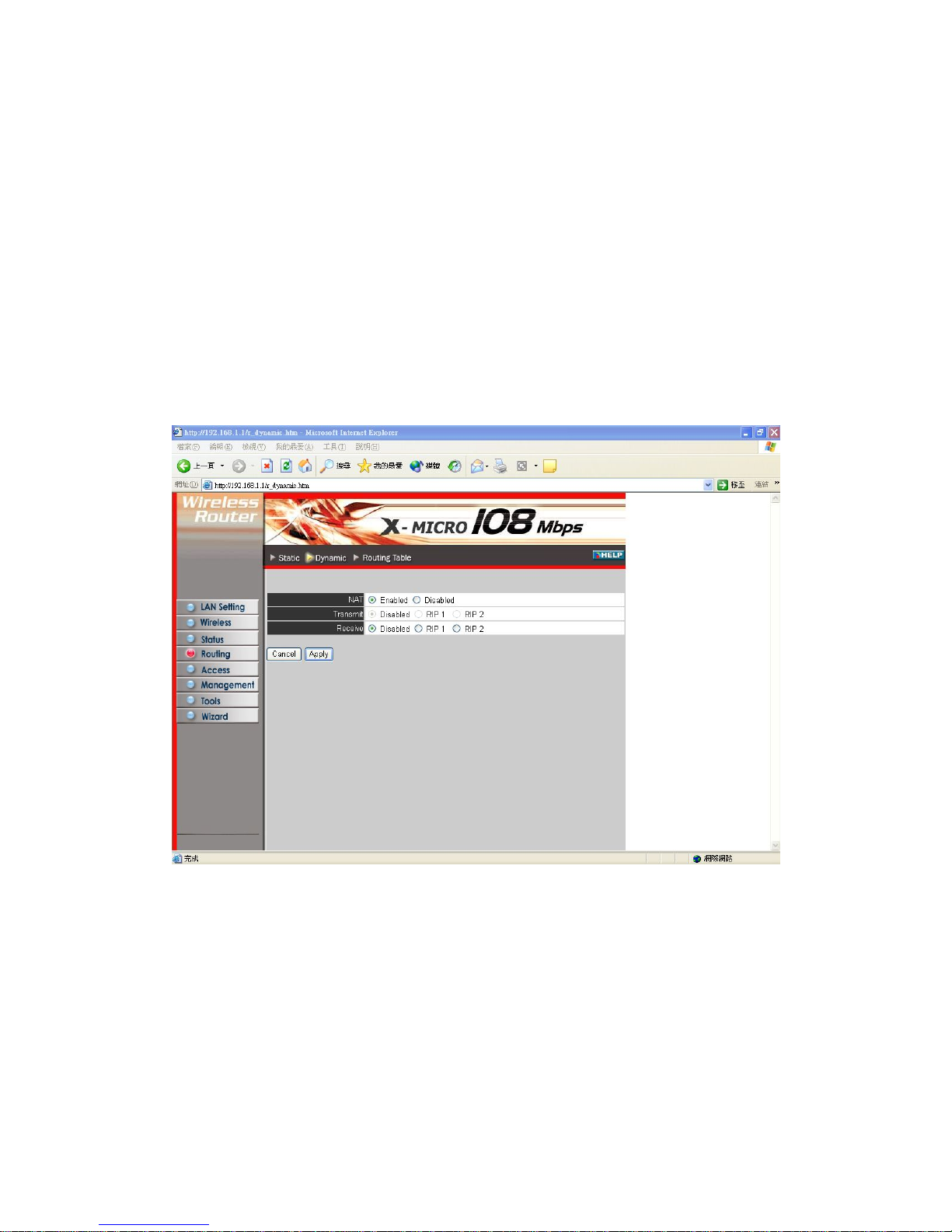
3.4.2 Dynamic
This screen enables you to set NAT parameters.
Update: Select one of the entrie
Delete: Select one of the entries in the static IP address table at the bottom of the page
and click Delete to remove the entry.
NAT: Click the radio buttons to enable or disable NAT.
the radio buttons to set the desired transmit parameters, disabled,
RIP 1, or RIP 2.
IP
Transmit: Click
Receive: Click the radio buttons to set the desired transmit parameters, disabled, R
1, or RIP 2
34
Page 35
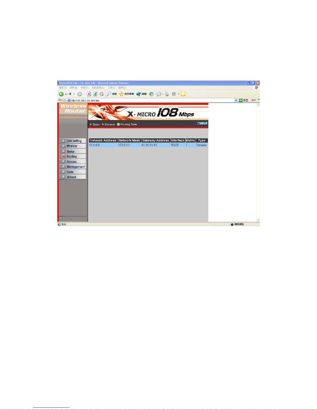
3.4.3 Routing Table
is a
ection topology.
This screen enables you to view the routing table for the router. The routing table
database created by the router that displays the network interconn
Network Address: Displays the network IP address of the connected node.
Network Mask: Displays the network (subnet) mask of the connected node.
Gateway Address: Displays the gateway address of the connected node.
s a static or dynamic IP address
t
Interface: Displays whether the node is connected via a WAN or LAN.
Metric: Displays the metric of the connected node.
Type: Displays whether the node ha
3.5 Access
This page enables you to define access restrictions, set up protocol and IP filters,
create virtual servers, define access for special applications such as games, and se
firewall rules.
35
Page 36
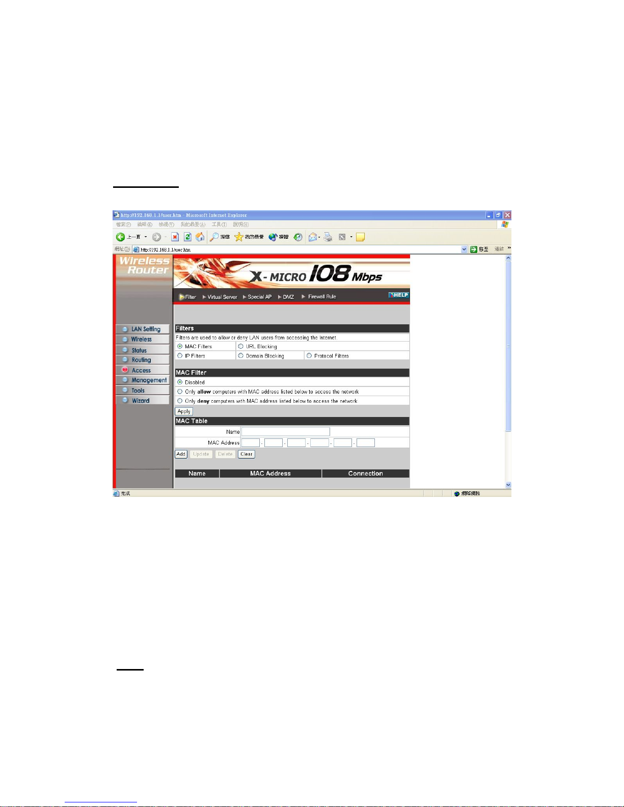
3.5.1 Filters
Using filters to deny or allow the users to access. Five types of filters to select:
MAC, URL blocking, IP, Protocol filter and Domain blocking.
AC Filters:
M
MAC Filter: Enables you to allow or deny Internet access to users within the LAN
based upon the MAC address of their network interface. Click the radio button next to
isabled to disable the MAC filter .
Once the function of MAC filter is disable, those listed in the MAC Table
are allowed Internet access.
Enable: All users are allowed Internet access except those user in the MAC Table are
deny Internet access.
MAC Table: Use this section to create a user profile which Internet access is denied
or allowed. The user profiles are listed in the table at the bottom of the page.
(
Note:
D
Disable:
Click anywhere in the item. Once the line is selected, the fields automatically
load the item's parameters, which you can edit.)
Name: Type the name of the user to be permitted/denied access.
MAC Address: Type the MAC address of the user's network interface.
36
Page 37
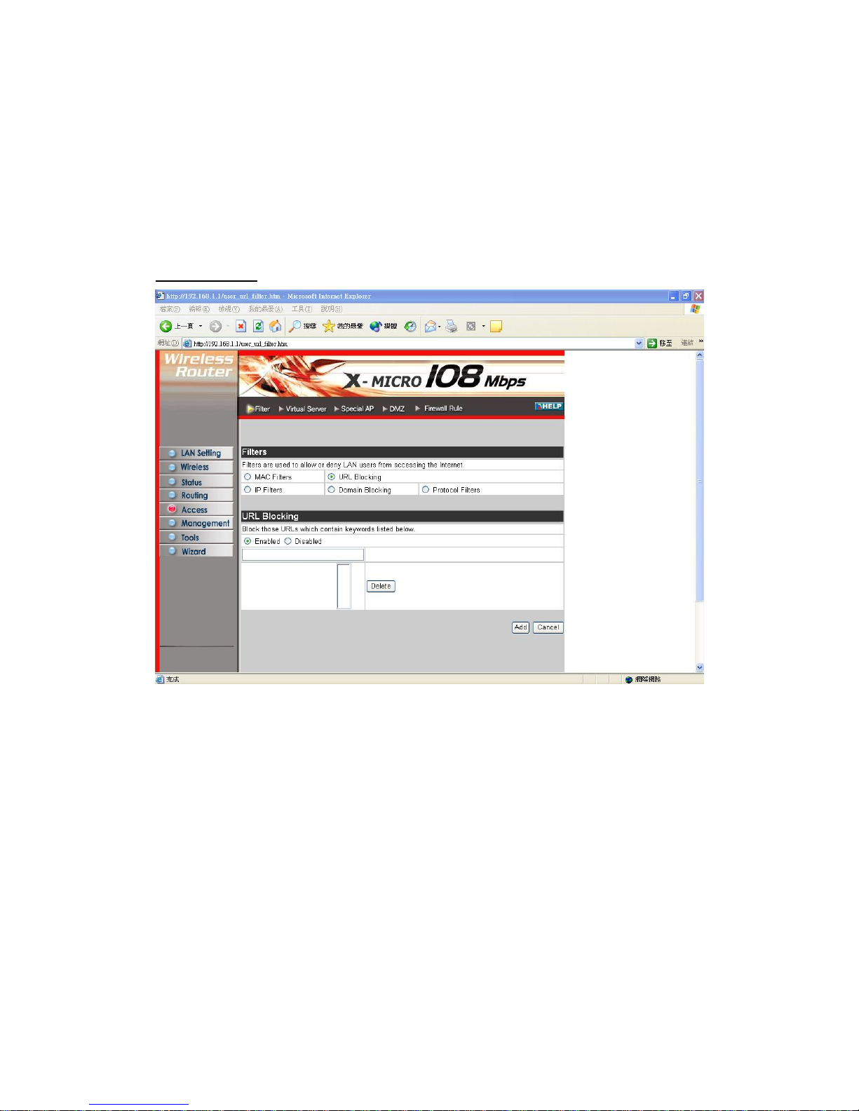
Add: Click to add the user to the list at the bottom of the page.
ase all fields and enter new information.
URL Blocking:
Update: Click to update information for the user, if you have changed any of the
fields.
Delete: Select a user from the table at the bottom of the list and click Delete to
remove the user profile.
New: Click New to er
You could enable URL blocking to deny the users from accessing the specified URL.
Add those specified URL in the text box.
37
Page 38
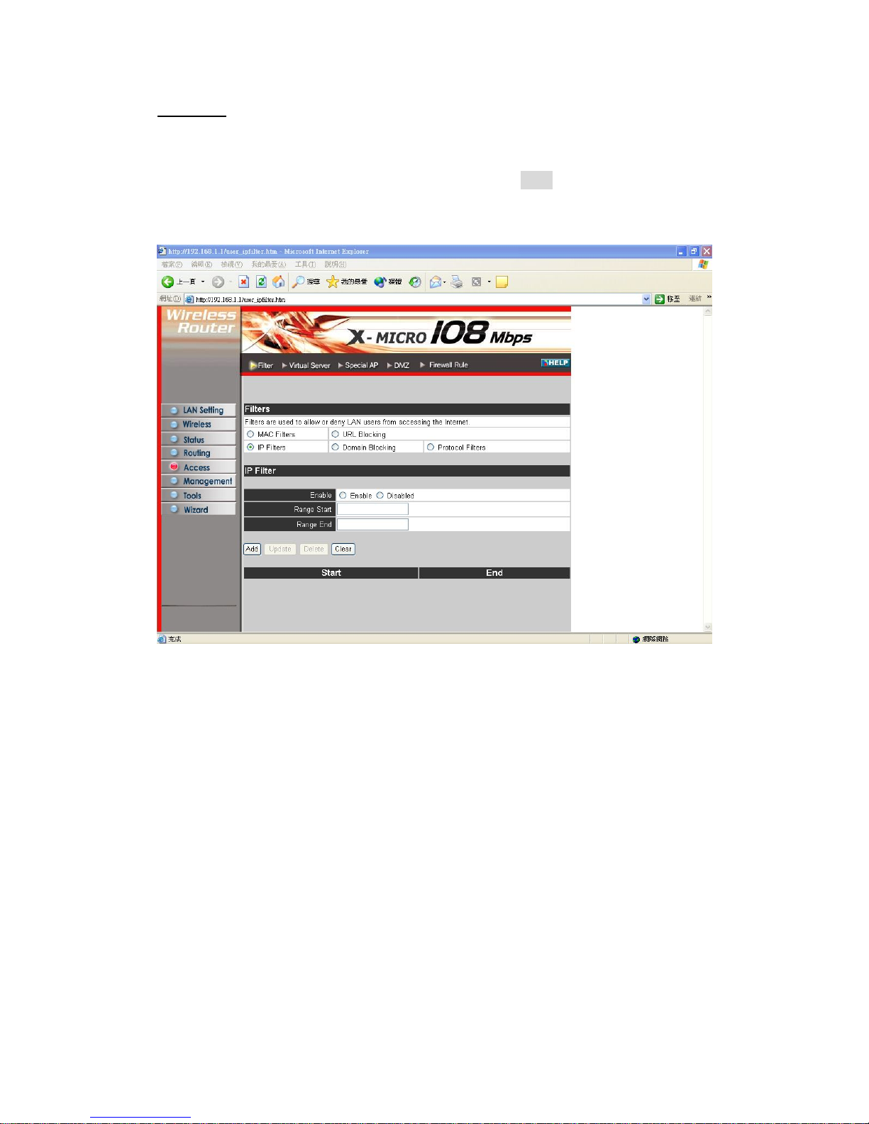
IP Filters:
This screen enables you to define a minimum and maximum IP address range filter;
all IP addresses falling in the range are not allowed Internet access. The IP filter
profiles are listed in the table at the bottom of the page. (
Note
: Click anywhere in the
item. Once the line is selected, the fields automatically load the item's parameters,
which you can edit.)
Enable: Click to enable or disable the IP address filter.
Range Start: Type the minimum address for the IP range. IP addresses falling
between this value and the Range End are not allowed to access the Internet.
Range End: Type the minimum address for the IP range. IP addresses falling between
this value and the Range Start are not allowed to access the Internet.
Add: Click to add the IP range to the table at the bottom of the screen.
Update: Click to update information for the range if you have selected a list item and
have made changes.
Delete: Select a list item and click Delete to remove the item from the list.
New: Click New to erase all fields and enter new information.
38
Page 39
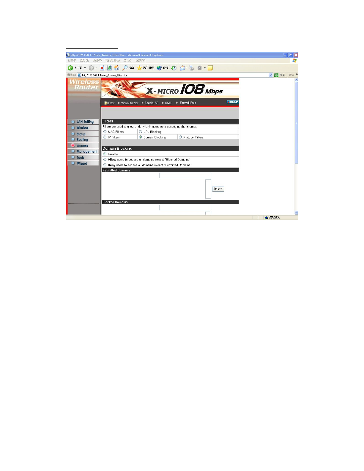
Domain Blocking:
You could specify the domains which allow users to access or deny by clicking one of
the two items. Also, add the specified domains in the text box.
39
Page 40
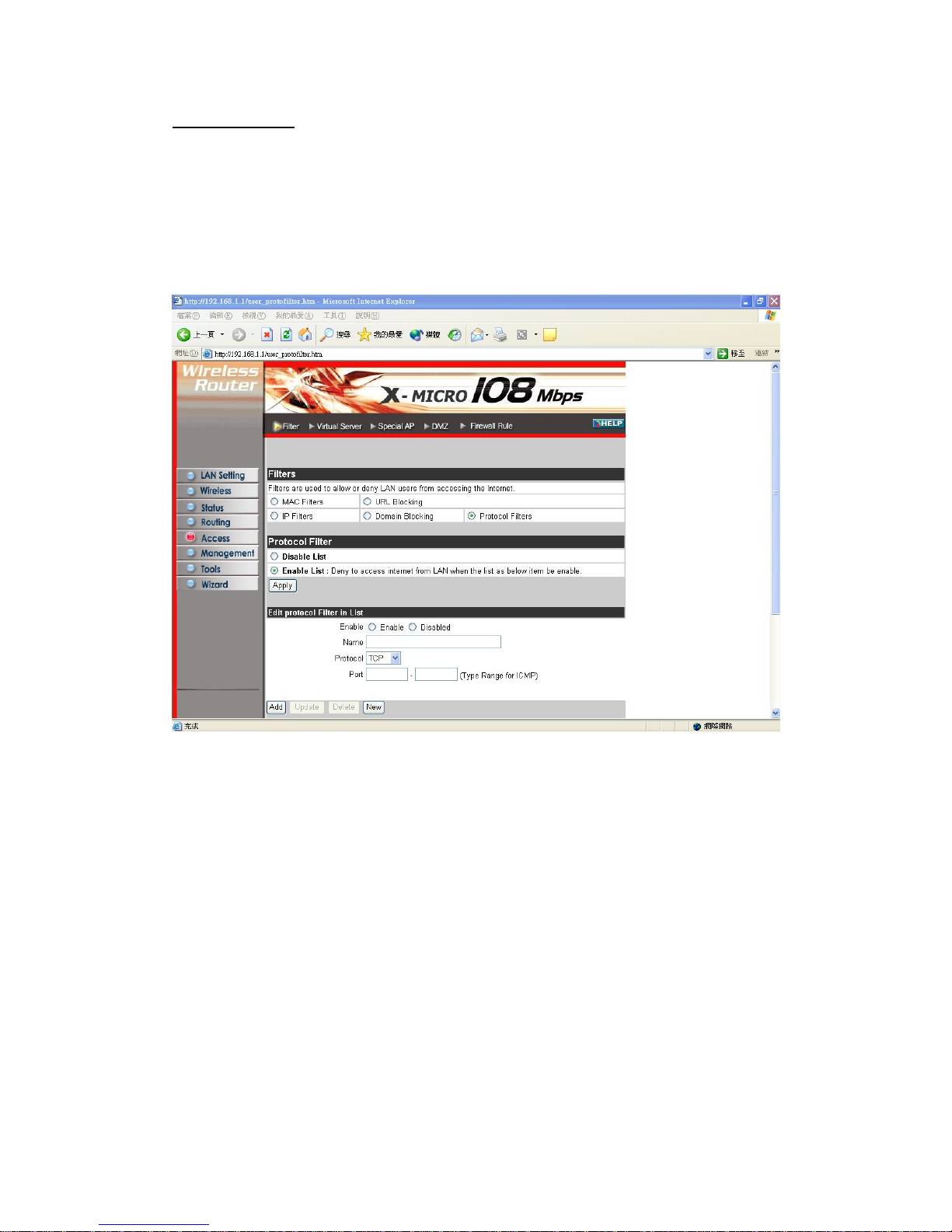
Protocol Filters:
and deny access based upon a communications
protocol list you create. The protocol filter profiles are listed in the table at the
This screen enables you to allow
bottom of the page.
Note: When selecting items in the table at the bottom, click anywhere in the item. The
line is selected, and the fields automatically load the item's parameters, which you can
edit:
40
Page 41
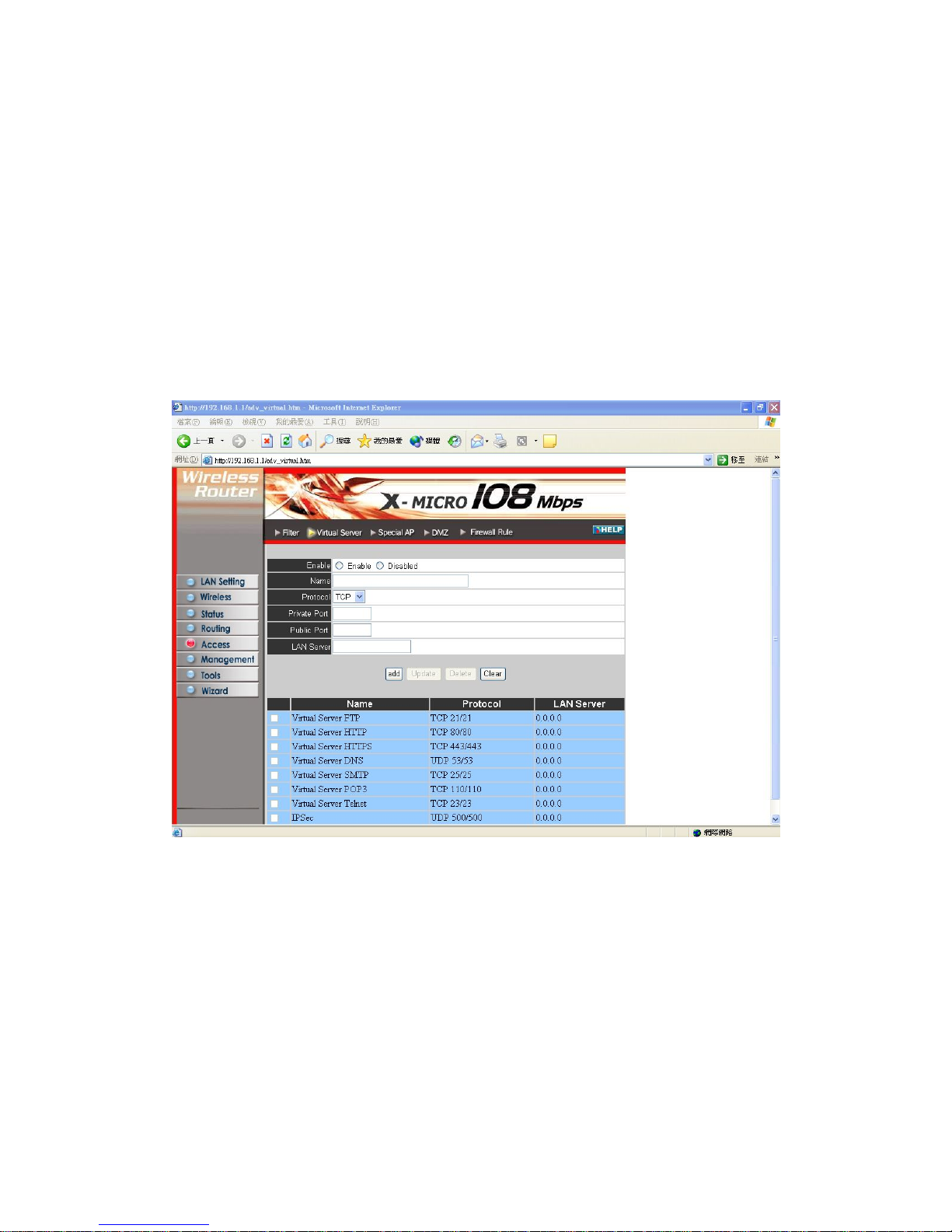
3.5.2 Virtual Server
This screen enables you to create a virtual server via the router. If the router is set as a
virtual server, remote users requesting Web or FTP services through the WAN are
e LAN. The router redirects the request via the protocol
and port numbers to the correct LAN server. The Virtual Sever profiles are listed in
oad the item's parameters, which you can
directed to local servers in th
the table at the bottom of the page.
Note: When selecting items in the table at the bottom, click anywhere in the item. The
line is selected, and the fields automatically l
edit.
Enable: Click to enable or disable the virtual server.
Name: Type a descriptive name for the virtual server.
will be used to provide access to
ss that will be assigned to the virtual server.
update information for the virtual server if you have selected a list
Protocol: Select the protocol (TCP or UDP) you want to use for the virtual server.
Private Port: Type the port number of the computer on the LAN that is being used to
act as a virtual server.
Public Port: Type the port number on the WAN that
the virtual server.
LAN Server: Type the LAN IP addre
Add: Click to add the virtual server to the table at the bottom of the screen.
Update: Click to
41
Page 42
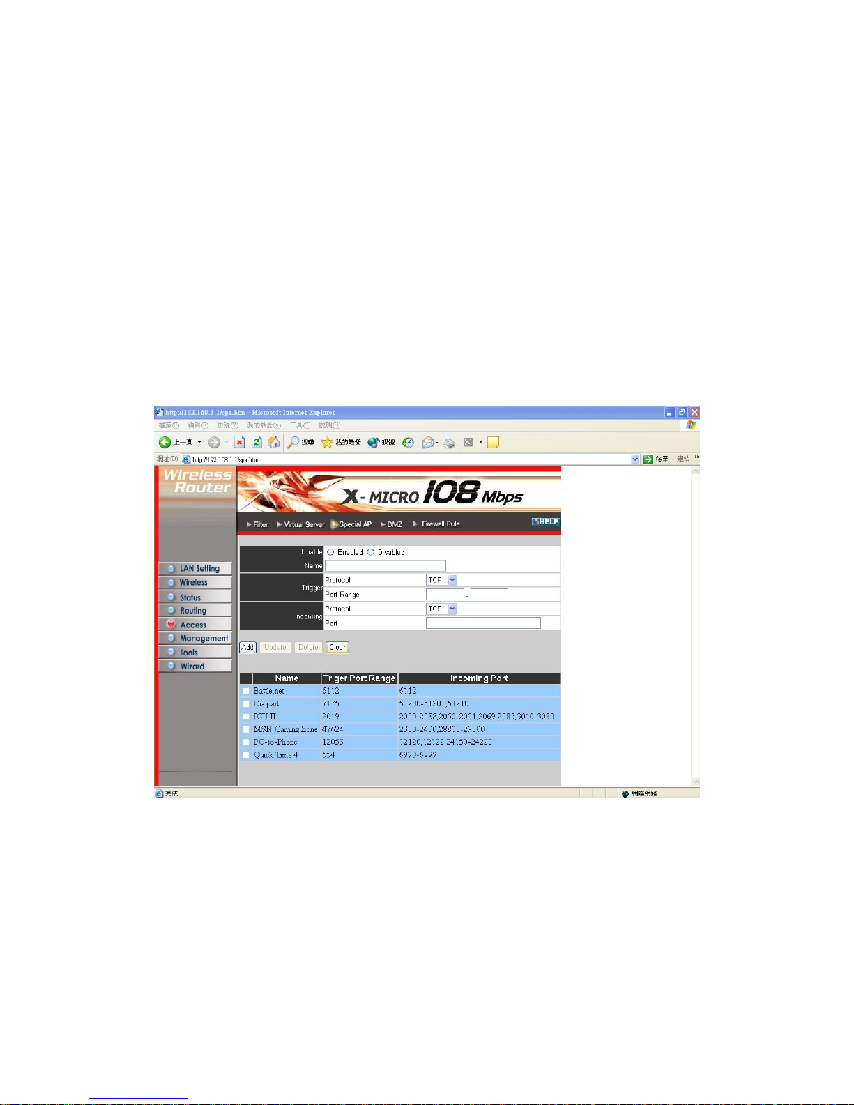
item and have made changes.
Delete: Select a list item and click Delete to remove the item from the list.
e
connections that are inhibited by NAT. The special applications profiles are
table at the bottom, click anywhere in the item. The
h you can
New: Click New to erase all fields and enter new information.
3.5.3 Special AP
This screen enables you to specify special applications, such as games, that requir
multiple
listed in the table at the bottom of the page.
Note: When selecting items in the
line is selected, and the fields automatically load the item's parameters, whic
edit.
Enable: Click to enable or disable the application profile. When enabled, users will
be able to connect to the application via the router WAN connection. Click Disabled
on a profile to prevent users from accessing the application on the WAN.
Name: Type a descriptive name for the application.
Trigger: Defines the outgoing communication that determines whether the user has
legitimate access to the application.
● Protocol: Select the protocol (TCP, UDP, or ICMP) that can be used to access
the application.
42
Page 43
● Port Range: Type the port range that can be used to access the application in the
re permitted to connect
● Protocol: Select the protocol (TCP, UDP, or ICMP) that can be used by the
● Port: Type the port number that can be used for the incoming communication.
ave made changes.
Delete: Select a list item and click Delete to remove the item from the list.
New: Click New to erase all fields and enter new information.
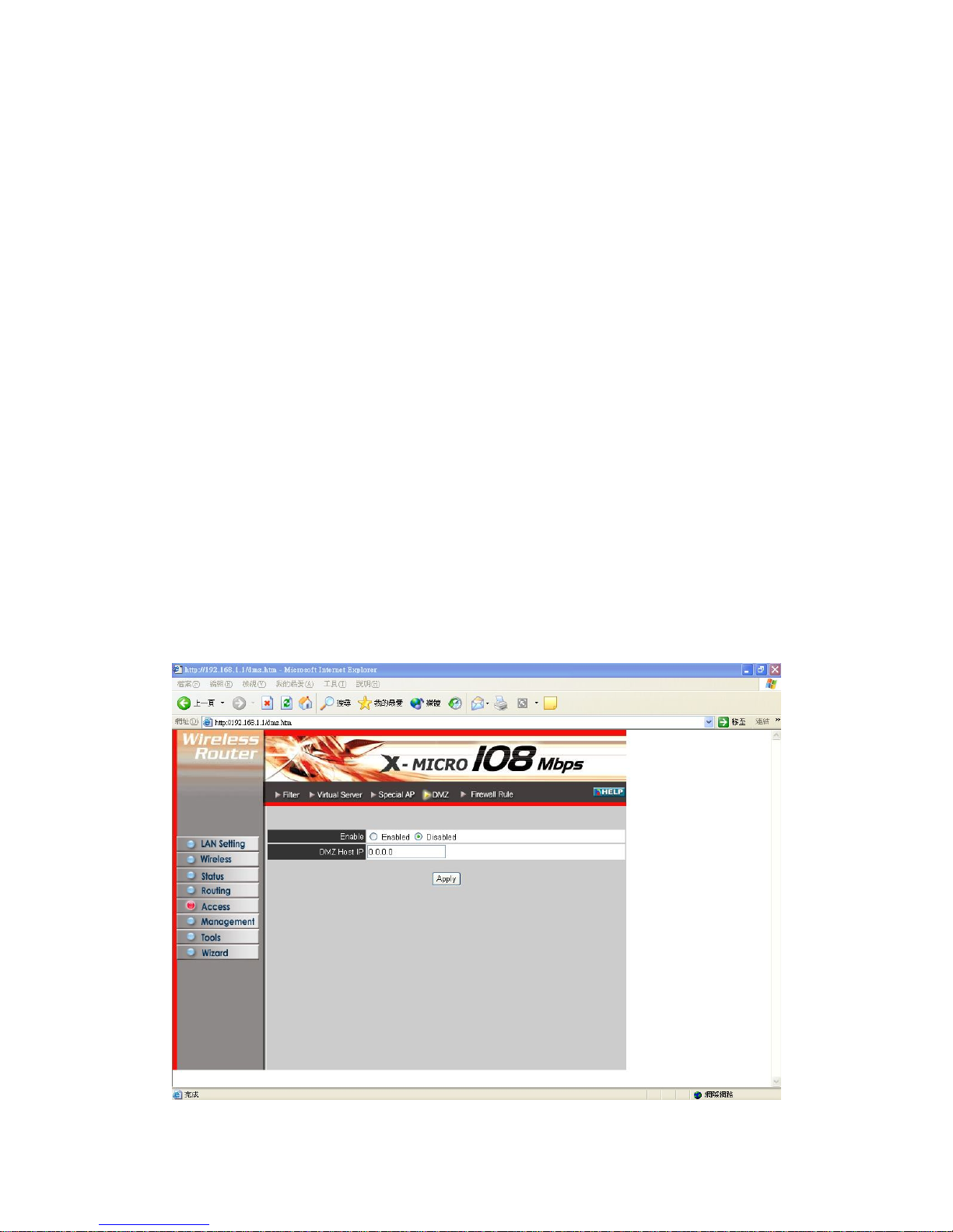
3.5.4 DMZ
This screen enables you to create a DMZ for those computers that cannot access
Internet applications properly through the router and associated security settings.
Note: Any clients added to the DMZ exposes the clients to security risks such as
viruses and unauthorized access.
text boxes.
Incoming: Defines which incoming communications users a
with.
incoming communication.
Add: Click to add the special application profile to the table at the bottom of the
screen.
Update: Click to update information for the special application if you have selected a
list item and h
43
Page 44
Enable: Click to enable or disable the DMZ.
DMZ Host IP: Type a host IP address for the DMZ. The computer with this IP
Apply: Click to save the settings.
sic firewall
e
sequence list--the lower the rule number, the higher the priority
address acts as a DMZ host with unlimited Internet access.
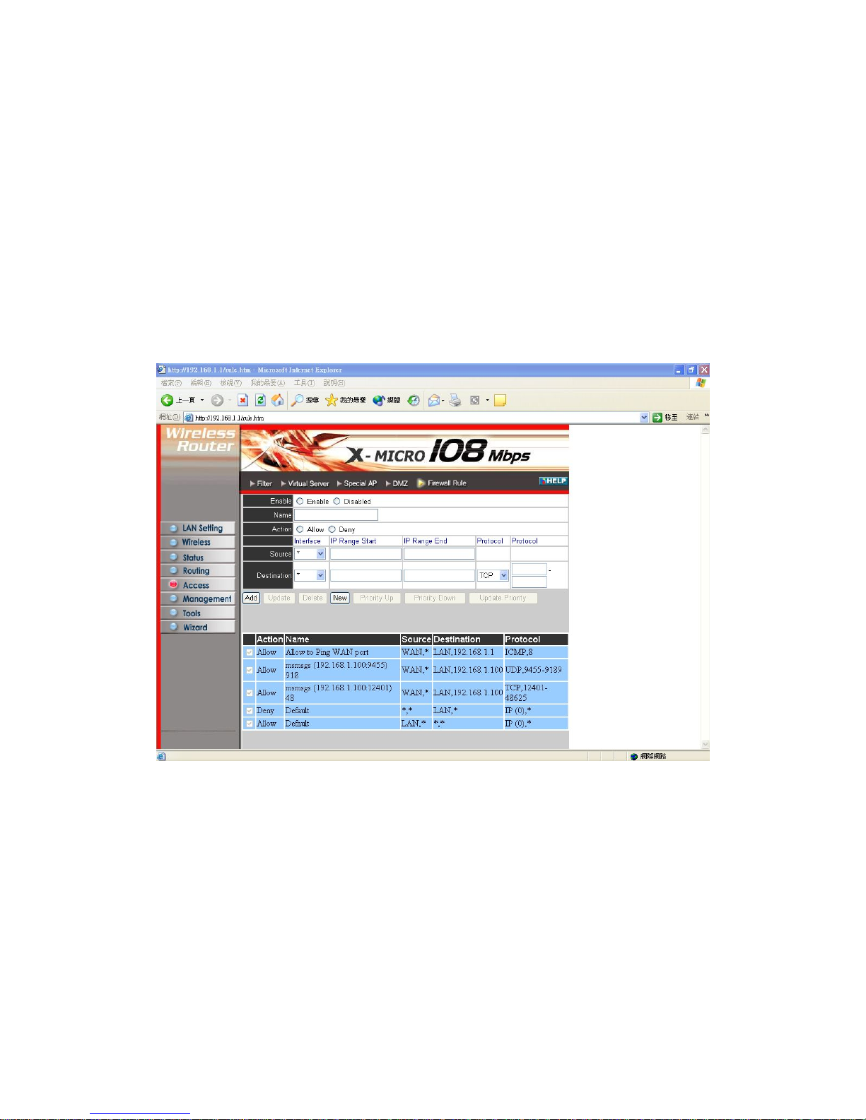
3.5.5 Firewall Rule
This screen enables you to set up the firewall. The router provides ba
functions, by filtering all the packets that enter the router using a set of rules. Th
rules are in an order
the rule has.
Enable: Click to enable or disable the firewall rule profile.
Name: Type a descriptive name for the firewall rule profile.
Action: Select whether to allow or deny packets that conform to the rule.
Inactive Timeout: Type the number of seconds of network inactivity that elapses
before the router refuses the incoming packet.
Source: Defines the source of the incoming packet that the rule is applied to.
● Interface: Select which interface (WAN or LAN) the rule is applied to.
● IP Range Start: Type the start IP address that the rule is applied to.
● IP Range End: Type the end IP address that the rule is applied to.
44
Page 45

Destination: Defines the destination of the incoming packet that the rule is applied to.
h interface (WAN or LAN) the rule is applied to.
● IP Range Start: Type the start IP address that the rule is applied to.
e protocol (TCP, UDP, or ICMP) of the destination.
● Port Range: Select the port range.
at the bottom of the screen.
Update: Click to update information for the rule if you have selected a list item and
have made changes.
Delete: Select a list item and click Delete to remove the item from the list.
New: Click New to erase all fields and enter new information.
Priority Up: Select a rule from the list and click Priority Up to increase the priority
of the rule.
Priority Down: Select a rule from the list and click Priority Down to decrease the
priority of the rule.
Update Priority: After increasing or decreasing the priority of a rule, click Update
Priority to save the changes.
● Interface: Select whic
● IP Range End: Type the end IP address that the rule is applied to.
● Protocol: Select th
Add: Click to add the rule profile to the table
45
Page 46
3.6 Management
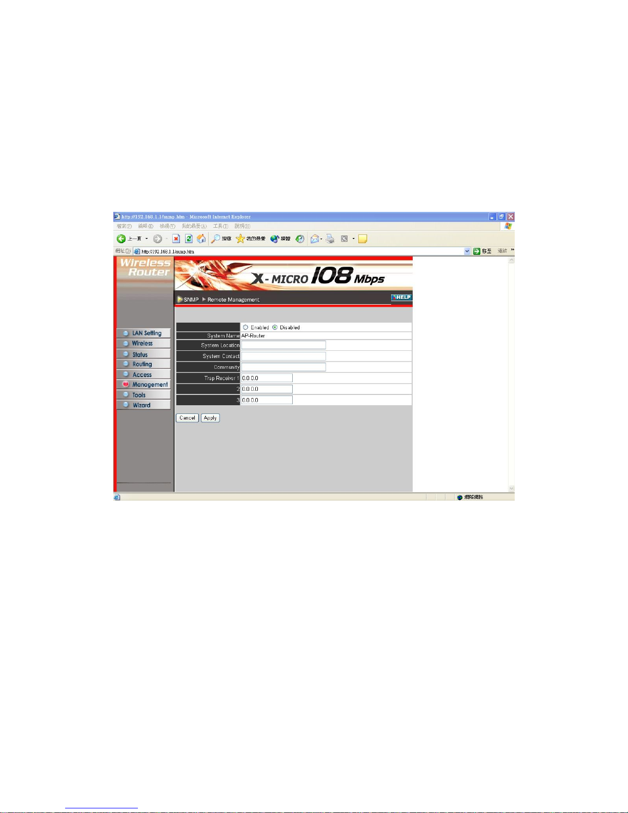
Management enables you to set up SNMP and Remote Management feature.
3.6.1 SNMP
This screen enables you to configure SNMP.
Enabled/Disabled: Click to enable or disable SNMP.
System Name: Displays the name given to the router.
messages passing through the network. The default
System Location: Displays the location of the router (normally, the DNS name).
System Contact: Displays the contact information for the person responsible for the
router.
Community: SNMP system name for exchanging SNMP community messages. The
name can be used to limit SNMP
name is 'public.'
Trap Receiver: Type the name of the destination PC that will receive trap messages.
46
Page 47
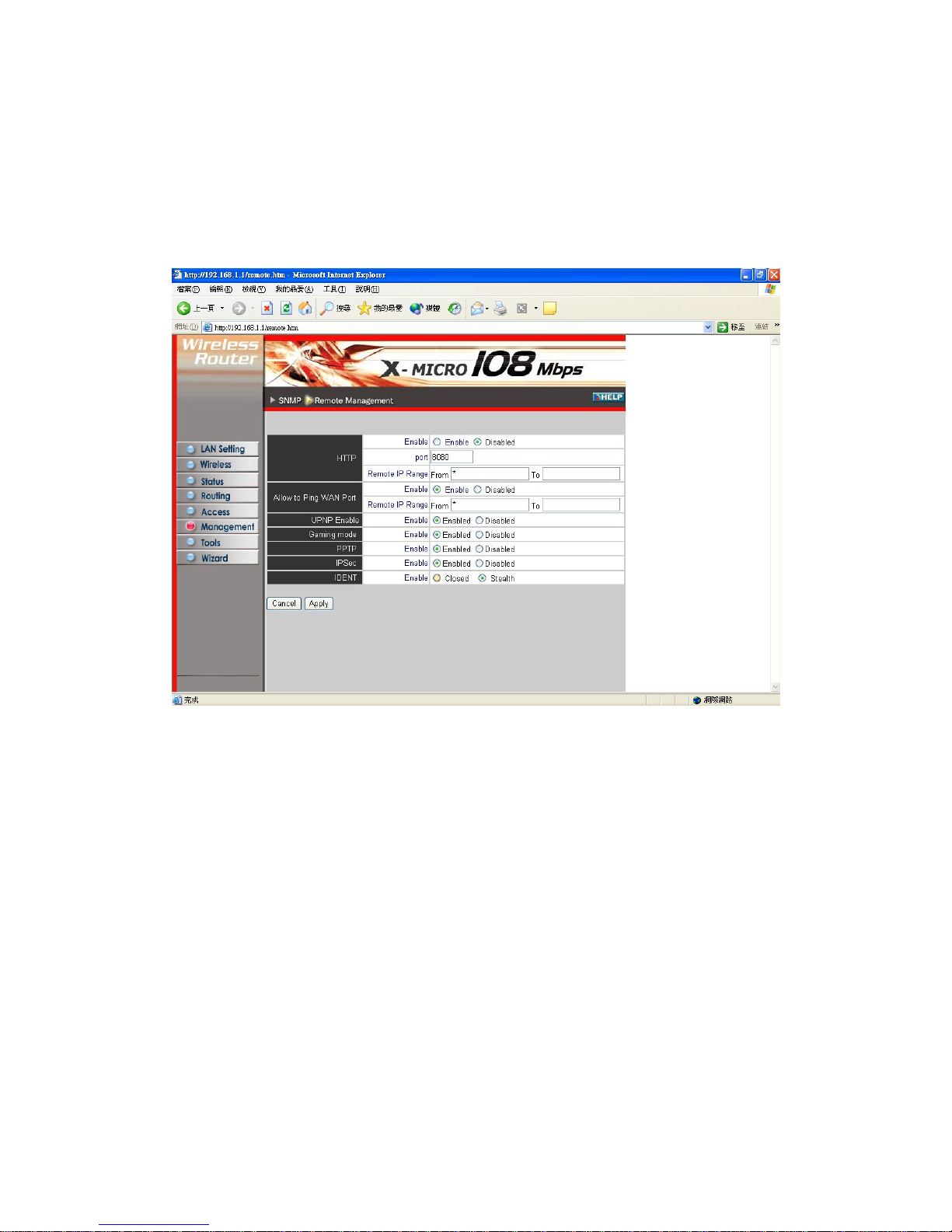
3.6.2 Remote Management
This screen enables you to set up remote management. Using remote management, the
router can be configured through the WAN via a Web browser. A user name and
password are required to perform remote management.
HTTP: Enables you to set up HTTP access for remote management.
● Enable: Click to enable or disable HTTP access for remote management.
Allow to Ping WAN Port: Type a range of router IP addresses that can be pinged
from remote locations
UPNP: UPNP is short for Universal Plug and Play which is a networking architecture
that provides compatibility among networking equipment, software, and peripherals.
The Router is a UPnP enabled router and will only work with other UPnP
devices/softwares. If you do not want to use the UPnP functionality, it can be disabled
by selecting "Disabled".
GAMING MODE: If you are experiencing difficulties when playing online games or
even certain applications that use voice data, you may need to enable Gaming Mode
for these applications to work correctly. When not playing games or using these voice
applications, it is recommended that Gaming Mode is disabled.
PPTP: Enables you to set up PPTP access for remote management.
IPSec: Enables you to set up IPSec access for remote management.
47
Page 48
IDENT: Default is closed. This enables you to set port 113 stealth.
3.7 Tools
configure router settings,
upgrade the firmware, and ping remote IP addresses.
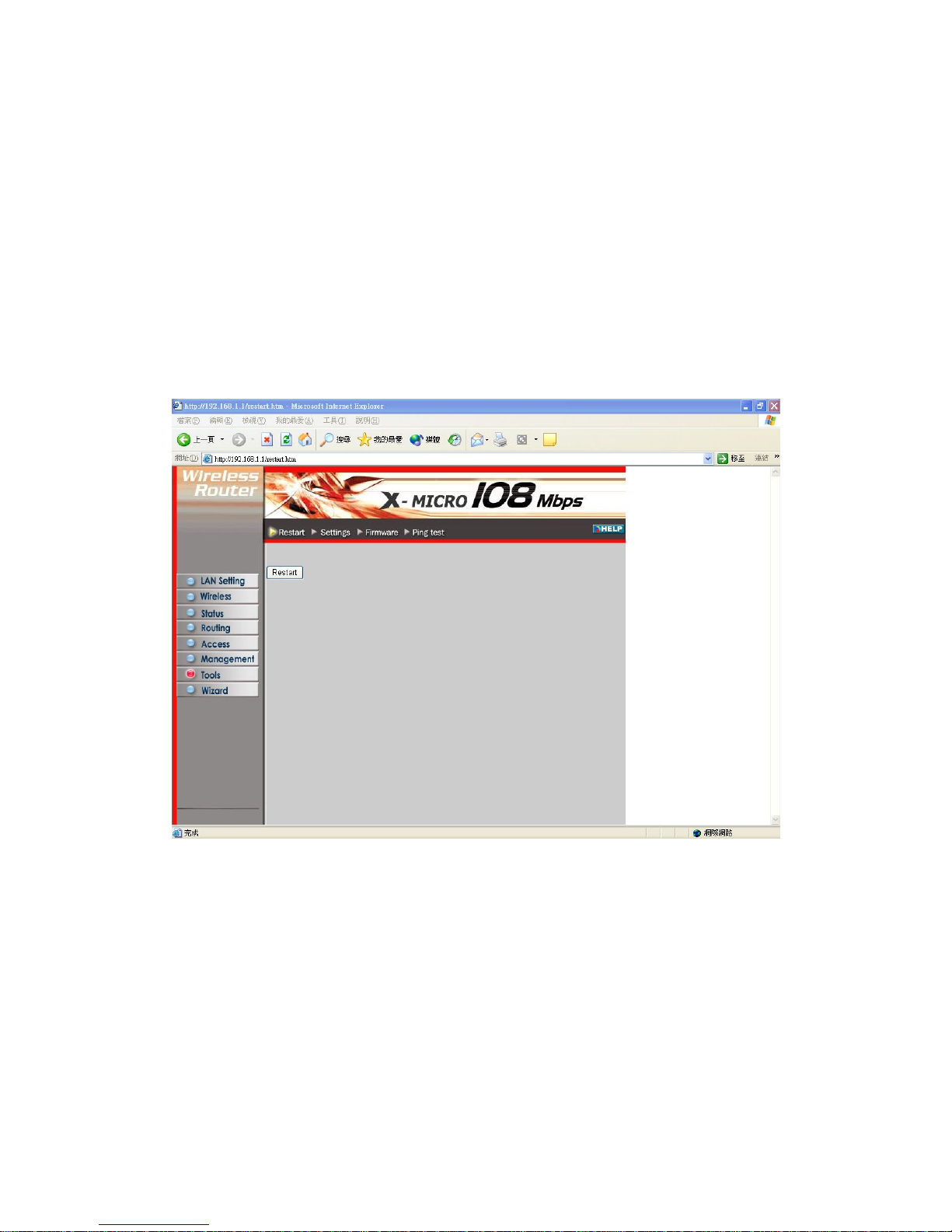
3.7.1 Restart
Click Restart to restart the system in the event the system is not performing correctly.
This page enables you to restart the system, save and load different settings as profiles,
restore factory default settings, run a setup wizard to
48
Page 49
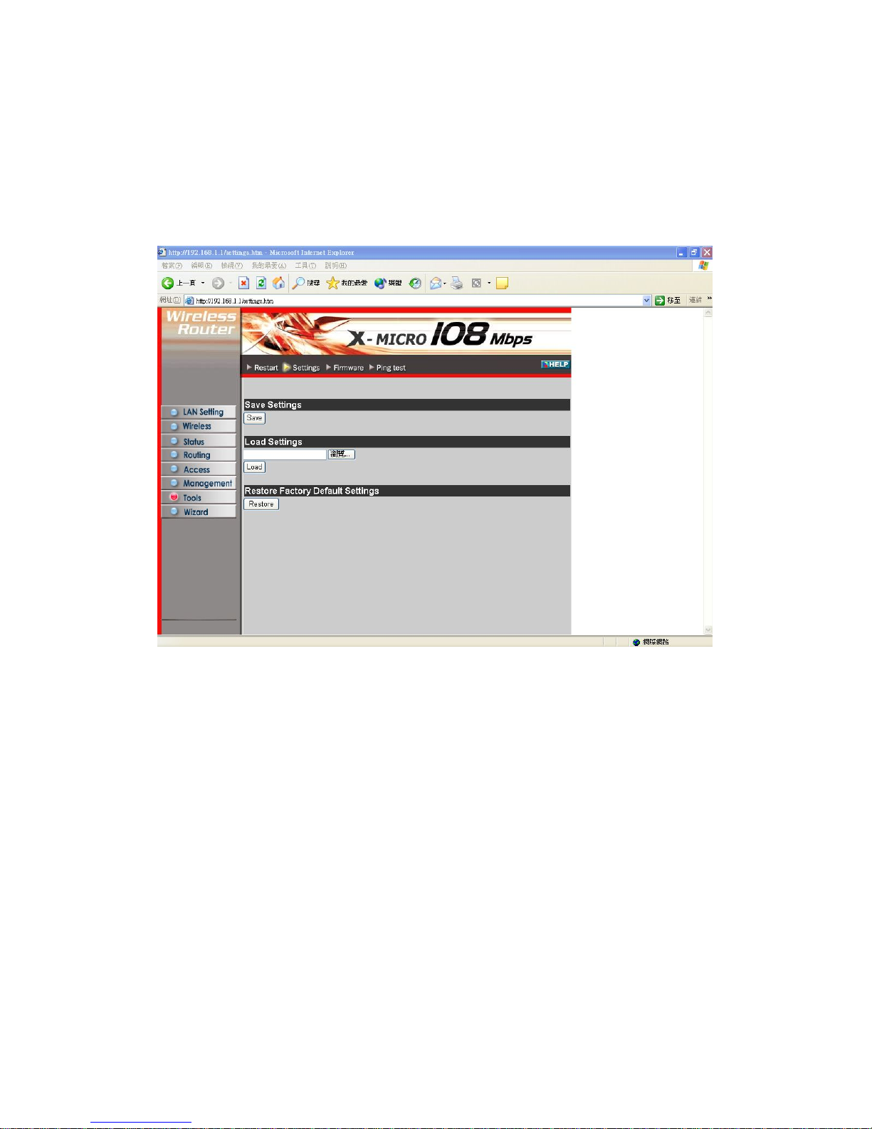
3.7.2 Settings
This screen enables you to save your settings as a profile and load profiles for
different circumstances. You can also load the factory default settings, and run a setup
wizard to configure the router and router interface.
Sav rrent configuration as a profile that you can load
Load to
load the profile's settings.
Restore Factory Default Settings: Click to restore the default settings. All
configuration changes you have made will be lost.
Setup Wizard: click to run a setup wizard that configures the router and interface
e Settings: Click to save the cu
when necessary.
Load Settings: Click Browse and go to the location of a stored profile. Click
49
Page 50
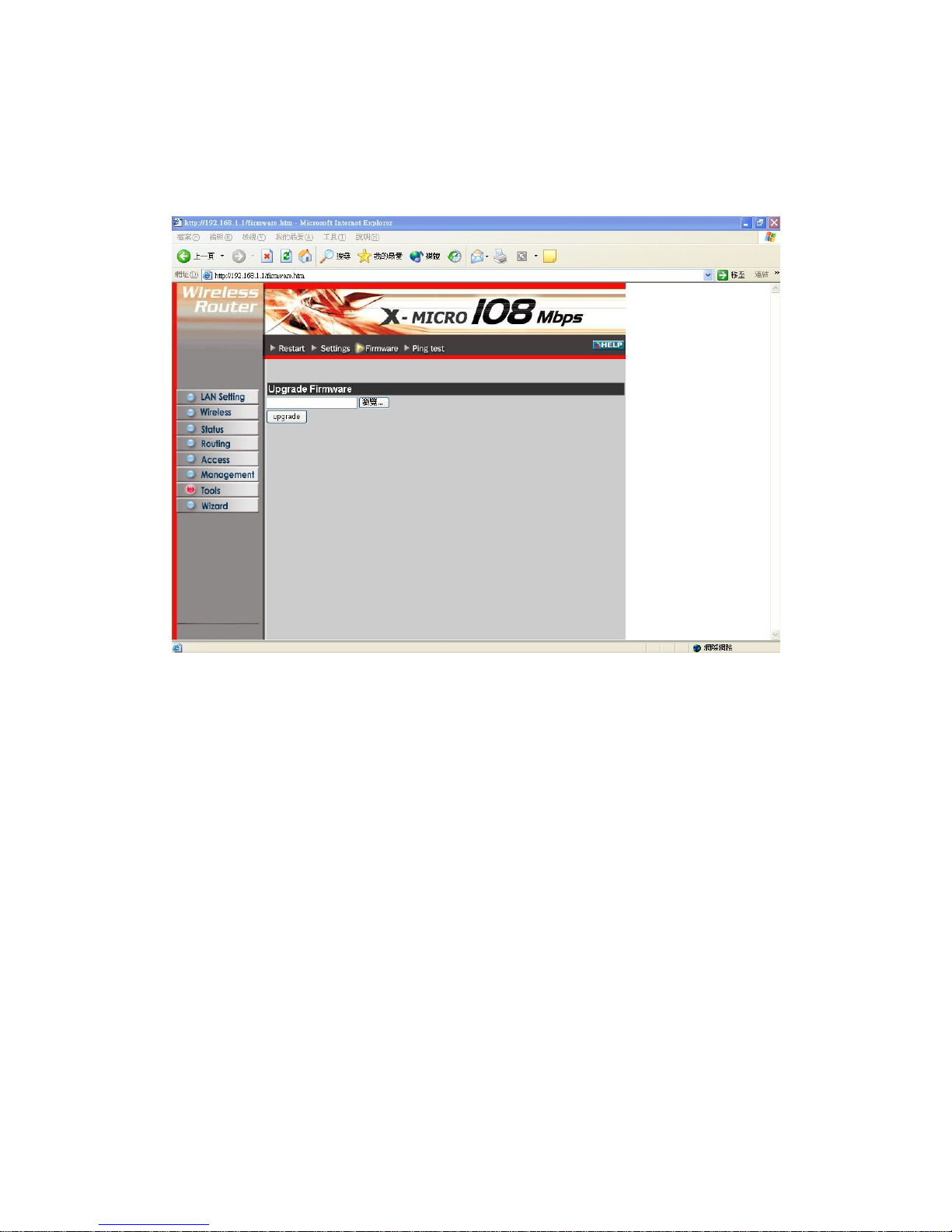
3.7.3 Firmware
This screen enables you to keep the router firmware up to date.
Please follow the below instructions:
. Download the latest firmware from the manufacturer's Web site, and save it to
your disk.
o to the location of the downloaded firmware file.
Upgrade to update the firmware to the latest release
1
2. Click Browse and g
Select the file and click
50
Page 51
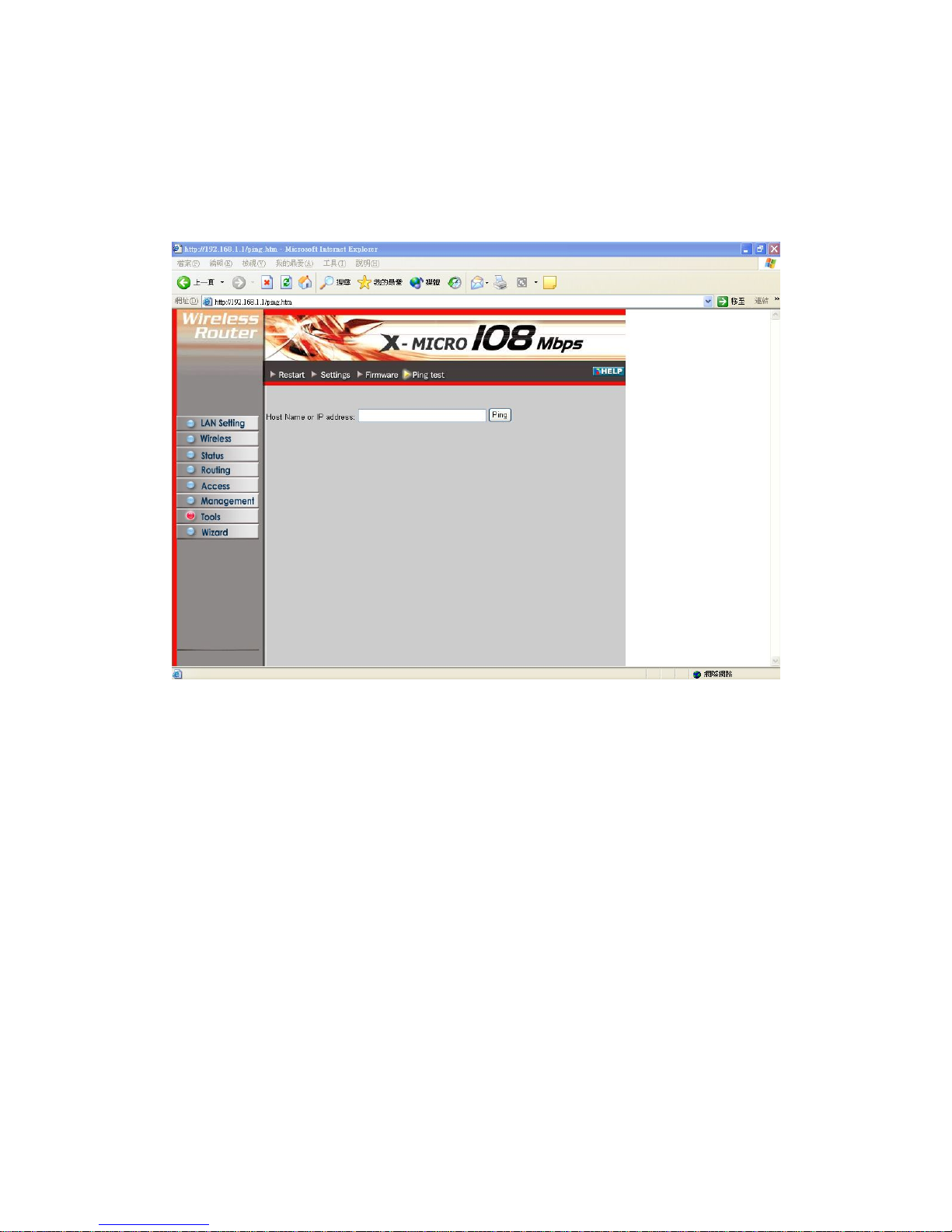
3.7.4 Ping Test
The ping test enables you to determine whether an IP address or host is present o
Internet. Type the host name or IP address in the text box and click Ping.
n the
4. Glossary
Access Point
An interview networking device that seamlessly connects wired and wireless
ge’s integrity.
nsecure WAN. DMZs provide a way for some clients to have
cted access to the Internet.
networks
Authentication
Authentication refers to the verification of a transmitted messa
DMZ
DMZ (DeMilitarized Zone) is a part of a network that is located between a secure
LAN and an i
unrestri
DHCP
DHCP (Dynamic Host Configuration Protocol) software automatically assigns IP
51
Page 52

addresses to client stations logging onto a TCP/IP network, which eliminates the need
to manually assign permanent IP addresses.
DNS
ands for Domain Name System. DNS converts machine names to the IP
domain name typically refers to an Internet site address.
emes which only allow specified data to be transmitted. For example,
se filters to prevent unwanted packets from being
itted. Firewalls are typically used to provide secure access to the Internet while
are refers to memory chips that retain their content without electrical power
interface.
r Protocol) is used to transfer files over a TCP/IP network, and is
y
s,
tions, and operating systems to exchange information.
twork.
DNS st
addresses that all machines on the net have. It translates from name to address and
from address to name.
Domain Name
The
DTIM
DTIM (Delivery Traffic Indication Message) provides client stations with information
on the next opportunity to monitor for broadcast or multicast messages.
Filter
Filters are sch
the router can filter specific IP addresses so that users canno t connect to those
addresses.
Firewall
Firewalls are methods used to keep networks secure from malicious intruders and
unauthorized access. Firewalls u
transm
keeping an organization's public Web server separate from the internal LAN.
Firmware
Firmw
(for example, BIOS ROM). The router firmware stores settings made in the
Fragmentation
Refers to the breaking up of data packets during transmission.
FTP
FTP (File Transfe
typically used for transferring large files or uploading the HTML pages for a Web site
to the Web server.
Gatewa
Gateways are computers that convert protocols enabling different network
applica
Host Name
The name given to a computer or client station that acts as a source for information on
the ne
HTTP
HTTP (HyperText Transport Protocol) is the communications protocol used to
connect to servers on the World Wide Web. HTTP establishes a connection with a
52
Page 53

Web server and transmits HTML pages to client browser (for example Windo
HTTP addresses all begin with the prefix 'http://
ws IE).
' prefix (for example,
and
ge sender that the destination node is not available).
at
a network address and allows messages to be routed to a different network or
owever, IP does not ensure delivery of a complete message—TCP provides
ss refers to the address of a computer attached to a
network. Every client and server station must have a unique IP address.
separated by periods
ample, 211.23.181.189).
cal Area Networks) are networks that serve users within specific
s,
s such as the
aximum Transmission/Transfer Unit) is the largest packet size that can be
network. Messages larger than the MTU are divided into smaller packets.
Address Translation - also known as IP masquerading) enables an
AT
http://www.yahoo.com).
ICMP
ICMP (Internet Control Message Protocol) is a TCP/IP protocol used to send error
control messages over the LAN (for example, it is used by the router to notify a
messa
IP
IP (Internet Protocol) is the protocol in the TCP/IP communications protocol suite th
contains
subnet. H
the function of ensuring delivery.
IP Address
The IP (Internet Protocol) addre
TCP/IP
Clients are assigned either a permanent address or have one dynamically assigned to
them via DHCP. IP addresses are written as four sets of numbers
(for ex
ISP
An ISP is an organization providing Internet access service via modems, ISDN
(Integrated Services Digital Network), and private lines.
LAN
LANs (Lo
geographical areas, such as in a company building. LANs are comprised of server
workstations, a network operating system, and communications link
router.
MAC Address
A MAC address is a unique serial number burned into hardware adapters, giving the
adapter a unique identification.
Metric
A number that indicates how long a packet takes to get to its destination.
MTU
MTU (M
sent over a
NAT
NAT (Network
organization to present itself to the Internet with one address. NAT converts the
address of each LAN node into one IP address for the Internet (and vice versa). N
53
Page 54

also provides a certain amount of security by acting as a firewall by keeping
ual IP addresses hidden from the WAN. individ
(Network) Administrator
The network administrator is the person who manages the LAN within an
ion. The administrator's job includes ensuring network security, keeping
etwork Time Protocol) is used to synchronize the realtime clock in a computer.
tion of data that is transmitted in network communications. Packets
y used to find out if a particular IP address is
is usually used by networks for debugging.
unications pathways in and out of computers and network devices
s and switches). Most PCs have serial and parallel ports, which are external
.
l
ithin
4.
r
orresponds with. No support is essential
ny of the routers or servers within the network the two PCs are connecting
n the smallest number of hops
organizat
software, hardware, and firmware up-to-date, and keeping track of network activity.
NTP
NTP (N
Internet primary and secondary servers synchronize to Coordinated Universal Time
(UTC).
Packet
A packet is a por
are also sometimes called frames and datagrams. Packets contain not only data, but
also the destination IP address.
Ping
Ping (Packet INternet Groper) is a utilit
present online, and
Port
Ports are the comm
(router
sockets for connecting devices such as printers, modems, and mice. All network
adapters use ports to connect to the LAN. Ports are typically numbered
PPPoE
PPPoE (Point-to-Point Protocol Over Ethernet) is used for running PPP protoco
(normally used for dial-up Internet connections) over an Ethernet.
PPTP
Point-to-Point Tunneling Protocol uses TCP to deal data for tunnel maintenance, and
uses PPP for sum up the information carried within the tunnel. The data carried w
the tunnel can be compressed or encrypted. The encryption method used is RSA RC
PPTP can operate when the protocol is supported only on the client and the serve
located on the other end that the client is c
from a
across.
Protocol
A protocol is a rule that governs the communication of data.
RIP
RIP (Routing Information Protocol) is a routing protocol that is integrated in the
TCP/IP protocol. RIP finds a route that is based o
54
Page 55

between the source of a packet and its destination.
o transmit data.
erver
ervers are typically powerful and fast machines that store programs and data. The
programs and data are shared by client machines (workstations) on the network.
SMTP
SMTP (Simple Mail Transfer Protocol) is the standard Internet e-mail protocol. SMTP
is a TCP/IP protocol defining m essage form at and includes a message transfer agent
that stores and forwards mail.
Subnet Mask
Subnet Masks (SUBNETwork masks) are used by IP protocol to direct messages into
a specified network segment (i.e., subnet). A subnet mask is stored in the client
machine, server or router and is compared with an incoming IP address to determine
whether to accept or reject the packet.
SysLog Server
A SysLog server monitors incoming Syslog messages and decodes the messages for
logging purposes.
TCP
(Transmission Control Protocol) is the transport protocol in TCP/IP that ensures
messages over the network are transmitted accurately and completely.
TCP/IP
TCP/IP (Transmission Control Protocol/Internet Protocol) is the main Internet
communications protocol. The TCP part ensures that data is completely sent and
received at the other end. Another part of the TCP/IP protocol set is UDP, which is
used to send data when accuracy and guaranteed packet delivery are not as important
(for example, in real-time video and audio transmission). The IP component of
TCP/IP provides data routability, meaning that data packets contain the destination
station and network addresses, enabling TCP/IP messages to be sent to multiple
networks within the LAN or in the WAN.
UDP
(User Datagram Protocol) is a protocol within TCP/IP that is used to transport
information when accurate delivery isn't necessary (for example, real-time video and
audio where packets can be dumped as there is no time for retransmitting the data).
Virtual Servers
Virtual servers are client servers (such as Web servers) that share resources with other
virtual servers (i.e., it is not a dedicated server).
RTS
RTS (Request To Send) is a signal sent from the transmitting station to the receiving
station requesting permission t
S
S
55
Page 56

WAN
WAN (Wide Area Network) is a communic ns network that covers a wide
geographic area such as a country (contrasted with a LAN, which covers a small area
such as a company building).
atio
56
Page 57

57
www.x-micro.com
 Loading...