

Page 1
Transceiver
Installation Manual
Exciter
Page 2

Warranty
Xmark's products are warranted against defects in materials and workmanship and shall
perform in accordance with published specifications for 1 year.
Xmark's warranty is limited solely to the repair or replacement of the defective part or
product. Xmark reserves the right to change product specifications without notice.
Regulatory Statements
United States - Federal Communication Commission (FCC)
This device complies with Part 15 of the FCC Rules. Operation is subject to the following
two conditions: (1) this device may not cause harmful interference, and (2) this device must
accept any interference received, including interference that may cause undesired
operation.
NOTE: This equipment has been tested and found to comply with the limits for a Class A
digital device, pursuant to Part 15 of the FCC Rules. These limits are designed to provide
reasonable protection against harmful interference when the equipment is operated in a
commercial environment. This equipment generates, uses and can radiate radio frequency
energy and, if not installed and used in accordance with the instruction manual, may cause
harmful interference to radio communications. Operation of this equipment in a residential
area is likely to cause harmful interference in which case the user will be required to correct
the interference at his own expense.
War ning: Any changes or modifications not expressly approved by Xmark could void the
user's authority to operate the equipment.
Canada - Industry Canada
The term "IC:" before the certification/registration number only signifies that Industry
Canada technical specifications were met.
Important Recommendation
Xmark’s systems are designed to assist staff in providing a high degree of safety for people
and assets and therefore should be used as a component of a comprehensive security
program of policies, procedures, and processes. As with every security system, Xmark
highly recommends regular system operational checks to verify functional integrity.
Page 3
Introduction
The exciter is an additional Low Frequency (LF) antenna for a Transceiver. By
using exciters, additional LF Fields can be created and the tag detection zones
can be extended.
Each Transceiver supports a maximum of three transceiver exciters. The
LF Fields of the Transceiver and all exciters will be in phase.
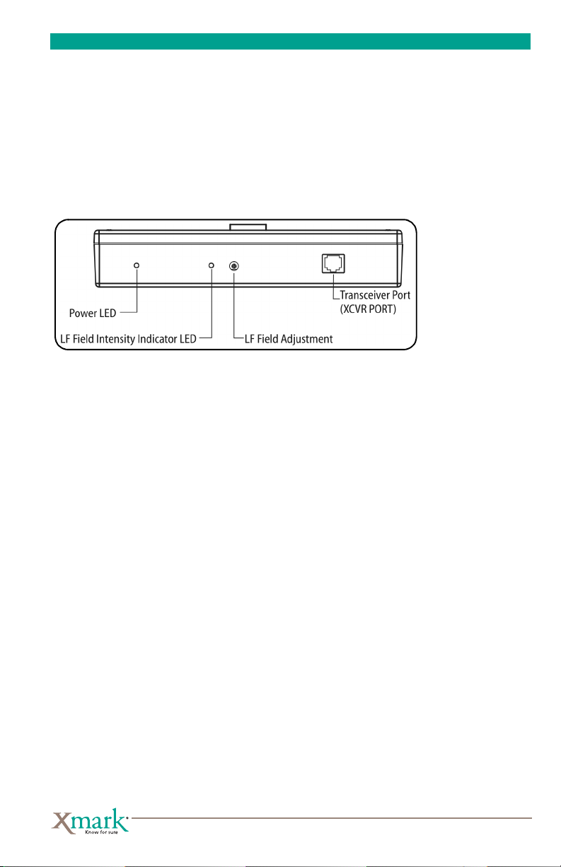
Figure 1: Exciter Front Panel
The exciter is connected to a transceiver (Part Number SR4TX01) from the
exciter’s XCVR PORT to any one of the transceiver’s three SATELLITE
EXCITERS ports using a standard ethernet cable (CAT5, EIA 568A termination). The exciter also draws its power from this connection.
1
Firmware Updates
The exciter does not contain firmware. Its operating features are dependent on
the Transceiver.
Installation Tips
When installing the exciter:
• Use both mounting holes to ensure that the exciter is secure.
• Mount the exciter so that the front panel is easily accessible and visible from the
floor. If mounting above a ceiling, place the exciter so that the front panel is visible
from the floor when a ceiling tile is removed.
• Check that the LF Field radiated by the exciter(s) and the Transceiver is continuous
(no dead spots) and that it covers the correct area. See “Configuration” on page 4.
Location Selection
Any of the following are suitable locations for an exciter:
Transceiver Exciter Installation Guide
Page 4

2
• On the wall above the egress point or monitored area.
•Inside a wall cavity.
• On the sidewall along the hallway mounted flat against the wall.
Location Considerations
When planning the exciter location, consider the following:
• Ceiling Height and Corridor Width — The exciter LF Field should extend to the
floor and from one wall of the corridor to the other. Tags must not be able to pass
under or around the LF Field.
• Any Nearby Metal — Large metal surfaces close to the exciter can distort the
LF Field in unpredictable ways. This effect can increase or decrease the LF Field
strength and even extend the LF Field shape. At times this effect can be used to
advantage but the desired result can only be obtained experimentally. Metal plate,
foil, or mesh must not come between the exciter and the tags to be queried and read.
The exciter top, bottom, and rear panels must be at least 3 in. (7.6 cm) from any
metallic surfaces.
• LF Field Shape — In the absence of large metal objects the LF Field is a sphere with
a 15 ft. (4.5 m) maximum radius centered around the exciter. As a result, the
LF Field range is unaffected by rotating the exciter, or by placing the exciter vertically or horizontally.
• Adjacent Floors — If the LF Field extends into adjacent floors, it will cause tags on
the adjacent floors to be reported as if on the exciter floor.
LF Field Coverage
When the exciter is used to monitor an egress point, such as a door or elevator,
the LF Field(s) should cover all possible approaches. As many as three exciters
can be used with a single Transceiver to modify the LF Field for this application.
Tags must be detected at least 8 ft. (2.4 m) before the door when the Transceiver
is part of a door locking system. This ensures adequate time for the lock to energize before the tag reaches the doorway.
The LF Field should not extend into adjacent areas, including adjacent floors,
containing tags. These tags could cause the Transceiver to activate the lock even
though tags are not approaching the exit.
Exciter Installation
To install the exciter:
1 Mount the exciter with #8 hardware using the two mounting holes.
2 Record the exciter location for later consideration.
3 Route the cable (not supplied) from the exciter to the Transceiver.
Transceiver Exciter Installation Guide
Page 5

3
4 Disconnect the Transceiver from its power supply.
5 Plug the cable into the Transceiver and the exciter.
6 Reconnect the Transceiver power supply.
7 Verify that the exciter power LED and the field intensity LED are on. See
Figure 1 for the location of these indicators. If they are not lit, check that the
Transceiver has power, and that the cable plug is properly inserted.
8 Adjust the exciter LF Field as described in “Configuration” below.
Configuration
The exciter is configured by adjusting the LF Field strength and size.
Before you set the LF Field Strength
Ensure that the Transceiver UHF Threshold is properly set: That is, the red
UHF Rx LED on the Transceiver is lit most of the time but continues to flicker
occasionally. If this is not true, set the UHF Threshold as described in the Transceiver Installation Manual.
The LF Field causes a tag to transmit a UHF message to the Transceiver. When
in test mode, the Transceiver beeps when a tag message is successfully received.
The beeping sound allows you to estimate the LF Field size.
The LF Field should be:
• Strong enough to make the tag respond throughout the desired area. That is, the
Transceiver beeps continually while the tag is anywhere within the desired area.
• Not strong enough to make the tag respond outside of the desired area. That is, the
Transceiver does not beep when the tag is outside of the desired area.
• Not strong enough to bleed onto adjacent floors. That is, the Transceiver does not
beep when the tag is on an adjacent floor.
To s et the LF Fi eld:
1 Set test mode by moving switch 1 down on the transceiver’s MODE DIP swtich
block.
2 Confirm tag operation by holding the tag close to the Transceiver. The Trans-
ceiver should beep continuously.
3 Using the tag, explore the desired coverage area while constantly re-orienting
the tag with respect to the exciter. The Transceiver should beep continuously.
Within the desired coverage area there may be locations with low LF Field
strength called dead spots. The Transceiver will stop beeping when the tag
enters a dead spot. The size and number of dead spots should be minimized.
However, a small number of dead spots may be acceptable.
Transceiver Exciter Installation Guide
Page 6

4
Some dead spots are less important than others. For example, if the aim is to
record the movement of tags through a door, a dead spot far from the door
may be less important than one near the door.
4 If the dead spot size and number is unacceptable, or if the LF field coverage
area is too small, increase the strength of the LF field by turning the LF FIELD
ADJ screw on the exciter clockwise.
The exciter adjustments are delicate. Do not turn the adjustments forcefully
to the limits. Do not needlessly wiggle or turn the adjustments.
As you turn the LF FIELD ADJ screw, the LF FIELD INTENSITY Indicator becomes:
w Brighter as you turn the ADJ screw clockwise and increase the LF Field strength;
—or—
w Dimmer as you turn the ADJ screw counterclockwise and decrease the LF Field strength.
5 If the tag is detected outside of the desired area, decrease the LF Field strength
by turning the adjustment counterclockwise until detection is limited to the
desired area.
Be aware that if the LF field reaches into adjacent floors it may cause tags on
those floors to be reported as if on the exciter floor.
6 Continue moving between steps 4 and 5 to achieve the best compromise
between a minimum number of dead spots, and limited detection.
7 If a suitable compromise cannot be achieved, consider relocating the exciter
and repeating the procedure.
8 When you have successfully set the LF Field strength, turn off test mode on the
transceiver and fix the exciter cables permanently in place.
Tip: If the exciter is above a suspended ceiling, place a colored adhesive dot on the
ceiling tile to mark the exciter location. Consult facility management before placing
the dots.
Transceiver Exciter Installation Guide
Page 7

Specifications
Part Number . . . . . . . . . . . . . . . . . . . . . . . . SR4EX01
Physical Specifications
Operating Temperature . . . . . . . . . . . . . . . . 32º F to 131º F (0º C to 55º C)
Humidity . . . . . . . . . . . . . . . . . . . . . . . . . . . 0 – 90% RH non-condensing
Size including mounting bracket
(W x H x D) . . . . . . . . . . . . . . . . . . . . . . . . 8.62 in. x 1.5 in. x 6.5 in.
(21.9 cm x 3.81 cm x 16.5 cm)
Maximum Cable Length . . . . . . . . . . . . . . . 20 ft. (6 m)
Weight including mounting bracket . . . . . . 19.4 oz. (551 g)
Electrical Specifications
Maximum Power . . . . . . . . . . . . . . . . . . . . . 150 mA @ 24 VDC —
by the Transceiver.
Transmit Frequency . . . . . . . . . . . . . . . . . . 307.2 kHz
LF Detection Zone . . . . . . . . . . . . . . . . . . . . 5 ft. – 15 ft. (1.5 m – 4.6 m), adjustable
The
exciter
is powered
5
Transceiver Exciter Installation Guide
Page 8

© 2005–2007 Xmark Corporation. All Rights Reserved. Xmark is a registered trademark of
309 Legget Drive Ottawa, ON Canada K2K 3A3
Telephone:1.866.55.XMARK
International:+1 (613) 592.6997
Facsimile:(613) 592.4296
Web site:www.xmark.com
E-mail:support@xmark.com
Xmark Corporation in North America. All other company and product names may be
trademarks of their respective companies.
Printed in Canada. October 2007. 981-000305-000 R02.
 Loading...