

Page 1
OPERATOR’S MANUAL
AN APPLIED DIGIT
AL COMPANY
Page 2
Contents: VeriChip H2 Reader Assembly Part Number
600-000515-000 (includes all of the following):
USER INSTRUCTIONS
Description
The VeriChip H2 Reader is hand-held Radio Frequency
Identification (RFID) reader which activates an implanted
VeriMed™ RFID Microtransponder with a low power, low
frequency (LF) electromagnetic field. The Reader
receives a unique 16-digit ID number from the VeriMed
Microtransponder. The ID number is used to provide, with
patient consent, physicians and other health
professionals access to a secure database that will
provide the implanted person’s identity and health
information provided by the patient.
Indications
The VeriChip H2 Reader is indicated for use as a portable
instrument that non-invasively reads the ID number of an
implantable VeriMed Microtransponder that is inserted
into the arm of the patient. When activated, the VeriMed
Microtransponder transmits a unique identification
number that will be displayed by the VeriChip H2 Reader
and may be used to access the patient’s identity and
authorized health information from a secure database.
Contraindications
None.
Description Part Number
VeriChip H2 Reader (1) 600-100313-000
with lanyard and instruction
card attached
Instructions for Use (1) 981-000302-000
Batteries AA (1 set of 4) 303-000014-000
Test Microtransponder (1) 670-000001-000
Bluetooth Receiver (1) 672-000001-000
with related Driver CD (1)
Folder Poster (1) 420-000025-000
Instructional CD (1) 672-000002-000
USB Cable (1) 301-000025-000
VeriChip H2™ Reader Activation with Manufacturer Settings
1. Press Button F1 and release to power on the Reader.
2. The Reader will enter a self diagnostic mode displaying
the following on the LCD screen:
a. “Initializing”
b. “VeriChip H2 Reader”
“BT Master Rev x.xx”
c. All Pixels active on the two line screen display
d. The number “8” will display in all positions
Check for missing segments. If segments are missing, do not
use and r
e. “Battery OK”
f. “BT Connecting - Inquiry Done - Please Wait”
3. Screen will display “PRESS F1 TO SCAN”
4. Press the F1 button and “SCANNING” will be displayed.
5. Perform the scanning process as described on page 3.
When a V
6.
be heard and the VeriMed ID number will be displayed on
the top line of the LCD and on the second line the
truction “PRES
ins
To initiate a new scan session press F1 again.
To scan for a different VeriMed Microtransponder press the F1 button
ear the pr
o cl
t
eturn Reader immediately for repair or replacement.
eriMed ID number is f
S F1 TO SCAN” is displayed.
vious ID number and to restart the scanning mode.
e
ound, an audible chirp will
21
Page 3
Prior to Scanning Patient
Scan test Microtransponder
provided with VeriChip H2 Reader
to verify unit functionality prior
..
anning Procedure for
Sc
ating an Implanted
Loc
to use (photo)
VeriMed Microtransponder
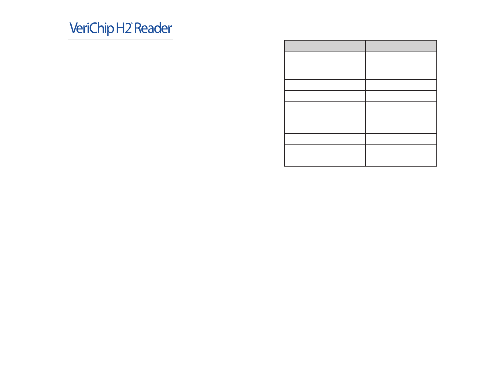
To scan/locate a Microtransponder
first activate the Reader as
described above. Press and release
the F1 button when instructed on the
DO NOT hold down F1 button
LCD.
during scan operation. Place the
Reader next to the skin, parallel and
along side the area to be scanned (see photo). Starting
about 2 inches above the elbow, move the scanner slowly
up the rear part of the arm. The injection site may vary
but it typically will be between the elbow and shoulder of
the triceps area of the upper arm. When a VeriMed
Microtransponder is located, the VeriChip H2 Reader will
emit an audible chirp and display the 16-digit ID number
on the LCD screen.
Depending on which communication configuration is
established, the VeriMed ID number will be entered via
USB or Bluet
web enabled VeriMed Patient Registry. If no
communication is es
used to manually enter the ID number.
ooth int
o the designat
tablished, the PC keyboard can be
3 4
ed entry field in the
Turning the Reader Off
The Reader can be turned off manually at
any time by simultaneously pressing
and holding down the F2 and F3 buttons.
If the Authorization Code is enabled and
an incorrect Authorization Code be entered, the unit will
immediately power-off.
The Reader will automatically power down should it
remain idle for 5 minutes.
Use of VeriMed Reader with Passive
Microtransponders of Different RFID Frequencies
The VeriMed H2 Reader is capable of reading the VeriMed
Microtransponder frequency of 134.2 kHz as well as 125
KHz. Place the Reader within the effective range of the
passive RFID Microtransponder (no more than 2.5 inches)
to obtain the ID number from the Microtransponder.
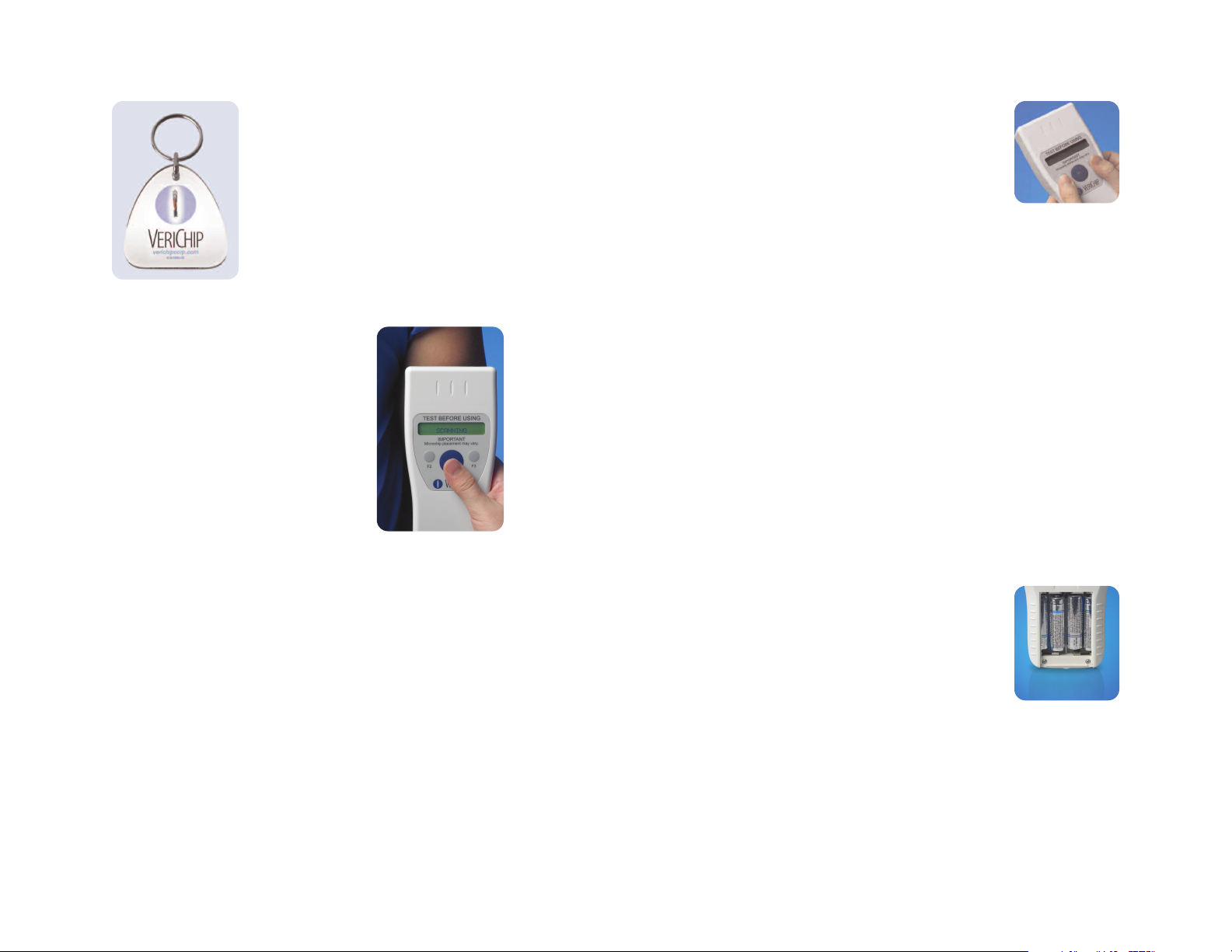
Installing/Replacing the Batteries
Remove the battery compartment door
by pressing the tab and sliding towards
the base of the Reader case. Insert 4 AA
alkaline batteries into the battery
compartment as indicated (see photo).
Replace the battery compartment cover and test the
Reader using the provided test RFID Microtransponder.
When the Reader battery power level drops to a point
insufficient to read a VeriMed Microtransponder the Reader
will automatically shut off. The Reader will display “LOW
BATTERY” followed by “REPLACE BATTERY”. When these
messages appear on the LCD, replace batteries immediately.
Page 4

Authorization Code Option
To provide a means of securing the VeriMed H2 Reader
against unauthorized use, an optional start-up
Authorization Code function is provided. This modality
consists of 8 entries of the two auxiliary buttons, F2 (left)
and F3 (right) in a predefined sequence. The factory
default setting is ‘disabled’, i.e. the unit will not prompt
the user to enter an Authorization Code, but rather will
immediately proceed to scan mode and establishing a
link with the host computer. This feature can be enabled
or disabled through the Configuration Mode (see
configuration mode section below).
If enabled, the Authorization Code is entered after the
Reader is turned on and self-tests are complete. The
user must press the two auxiliary buttons a total of 8
times in predefined sequence. This sequence can be
customized and stored in the EEPROM. The default
sequence (programmed at the time of manufacture) is:
F2,F2,F3,F3,F2,F3,F2,F3
Enabling Authorization Code
To enable authorization process, the user must send
the ‘?’ character from the HyperTerminal to the unit
via a serial link in Configuration Mode.
To disable authorization process, the user must send
the ‘!’ character from the HyperTerminal to the unit
via a serial link in Configuration Mode.
Changing the Authorization Code
Maintain a record of the Authorization Code for
future reference. Loss of Authorization Code
s will r
acces
To change this sequence, the user must power up the
unit and go into Configuration Mode. To enter the new
equire a call to customer service.
sequence, the user must send the ‘#’ character to the
VH2R over the serial link. Immediately after that the
unit will accept exactly 8 characters ‘l’ for F2 and ‘r’
for F1 (“l” for left and “r” for right button locations in
lowercase only) in the user defined sequence and the
new key is stored in the Reader EEPROM.
If the Code becomes lost, call customer service for
assistance.
If the key sequence is entered incorrectly, the unit
displays ‘ACCESS DENIED’ on the LCD and shuts
down after 1 second.
If the sequence is entered correctly, the unit
immediately tries connecting to the host according to
the set communication mode.
Configuration Mode
To operate in this mode the user should perform the
following actions:
• Connect the USB cable from the host computer to the
VH2R Reader.
• Turn on the VH2R Reader by pressing the F1 (large
center) and F2 button. The VH2R Reader will go through
its self-test procedure. Enter the Authorization sequence
as described later in this document if you are prompted
to “Enter Code” by the message on the unit’s LCD.
• Start the appropriate communication program on the
host computer system. For example, the user may
launch the HyperTerminal program and connect to the
serial port created by the USB driver. The VH2R reader
will stay in this idle mode for up to 5 minutes. The user
has two choices – to initiate a scan (normal operation)
er the c
or ent
until the timeout, the unit will po
communication program (HyperTerminal) should be set
to 9600 Baud, 8 data bits, one stop bit, no parity (8-N-1).
onfigur
ation mode. If no choice is made
wer down. The
Page 5

To enter the configuration mode, the user should send a
predetermined command from the host to VH2R (letter ‘c’
in lower case). The power down timer will be extended upon
receiving any character from the host system. When the
timer expires, the unit will power down. All configuration
settings are stored in non-volatile memory immediately
after they are entered. To exit the configuration mode, the
user can either use a special command from PC – letter ‘q’
in lower case (the VH2R will go into Idle mode), or press the
F1 button (the VH2R will enter scan mode).
An example of configuration menu screen:
VeriChip H2 Reader CONFIG MODE
m - BT Master
s - BT Slav
e
u - USB
r - Ricoh G3
@ - BT MAC
# - Unlock Code
? - Unlock Required
! - Unlock Not Requir
ed
q - Quit
VeriMed H2 Reader Communication
The unit has two communication devices – USB and Bluetooth.
Only one communication mode can be used at any time.
Both communication channels are bi-directional. When a
passive VeriMed Microtransponder is acquired by the
VH2R Reader, the ID number is sent to the host computer.
The host computer can also send certain information back
to the VH2R Reader. This feature is used to change current
e a
configurations of the VH2R Reader, including pos
switch between its communication modes (from USB to
BT and back) and utilizing the Authorization Code option.
sibl
VeriChip H2™ Reader Operation in USB Mode
To operate in this mode the user should perform the
following actions:
• Connect the USB cable from the host computer to the
VH2R Reader. The USB port is located in the rear of the
case. Lift the protective cover and insert the cable.
• To perform the scan, the user should press the F1
button once again. The VH2R will turn on the LF (low
frequency) interrogation field and try to acquire a
Microtransponder. The field will stay on for 12 seconds
or until a valid Microtransponder is acquired. If a
Microtransponder has not been acquired, the VH2R will
go into the idle mode. If a Microtransponder has been
acquired, its ID number will be displayed on VH2R LCD
and sent to the host computer via the USB interface.
After this the VH2R will enter its idle mode and be ready
for another scan session or power down after 5
minutes. The unit can be powered down from this state
by pressing the two smaller buttons (F2 and F3)
simultaneously.
Note: Operating in the USB mode, the unit does not monitor
the status of communication link. That is, if the USB cable
becomes disconnected, the user will not be notified. If the
cable was not connected to the host system, the latter may
not be able to open the serial port. Disconnecting the cable
during the communication session may produce an error on
the host system.
VeriChip H2 Reader Operation
in Bluetooth Master Mode
In the Master mode the VH2R performs the discovery and
then dials the host computer system acting as a Bluetooth
(BT) master. As a consequence, no action is required on the
87
Page 6

host computer side. For example, a communication program
(HyperTerminal or “keyboard wedge”) may be open and left
running regardless of the VH2R being powered on or off. The
VH2R stores the host’s BT MAC address in its non-volatile
memory, and will dial only this address no matter how many
devices it discovers performing the inquiry. The MAC address
should be entered into the device by using other communication
modes (such as USB or BT Slave) that does not require
knowledge of this address. When Bluetooth encryption is
desired, it must be enabled on both sides of the link (an identical
passkey word supplied). In this case the passkey should be
entered on the PC side only once, during the ‘pairing’ process. All
subsequent connections between the members of the same pair
will be encrypted automatically, and establishing subsequent
links will not require entering the passkey unless the devices
become ‘unpaired’.
The operation is performed as follows:
To operate in this mode the user should perform the following actions:
• Bring the VH2R and host system within Bluetooth range
(about 10m under most conditions).
• Start the communication program on the host side
(HyperTerminal or keyboard wedge). The exact number of
the serial port to be used for this connection should be
provided by the Bluetooth service. It has been noticed that
although Windows XP has some built-in Bluetooth support
that can be used to establish the connection, it is
significantly slower than a proprietary stack that comes
with particular BT hardware (e.g. BlueSoleil).
• Power up the VH2R by pressing the F1 button and enter the
authorization code if prompted. The device will try to discover
and dial the host. If this is the first time connection, the user
must enter the passkey on the PC side to allow the VH2R
connection to the PC. If this process has been successful, the
user will be prompted to press the F1 button once again to
initiate scanning f
the F1 button without waiting for connection, the VH2R will
abort the attempt and go into standalone mode. If the unit
or a Microtransponder. If the user presses
a priori
cannot discover the host within 20 seconds, it will
automatically abandon the attempt and proceed in
standalone mode.
• The VH2R will turn on the low frequency (LF) interrogation field
and try to acquire a Microtransponder. The field will stay on for
12 seconds or until a valid Microtransponder is acquired. If a
Microtransponder has not been acquired, the VH2R will go into
idle mode producing a corresponding message on the LCD. If a
Microtransponder has been acquired, its ID number will be
displayed on VH2R LCD and sent to the host via the BT
interface (if the connection had been established). After this
the VH2R will enter its idle mode and be ready for another scan
or power down after 5 minutes. To shut the unit down earlier,
the user can press the F2 and F3 buttons simultaneously.
VeriChip H2 Reader Configuration Options
USB Override.
As described above, the normal way of changing the connection
mode is through the established USB (serial) connection.
However, to recover from a situation when the Bluetoothenabled host becomes unavailable for some reason (for
example: The unit had been configured to work as Bluetooth
master and programmed with a particular slave MAC address,
but that host device is not available), an emergency override
procedure exists.
To activate the override, the user should power up the VH2R
while holding down the Left auxiliary button (F2) until the unit
enters the self-test mode. The unit will switch into the USB
connection mode regardless of what had been stored in the
EEPROM, and thus enable the user to connect the Reader to the
host by means of USB cable and perform necessary changes.
This override is not memorized in the EEPROM and so is valid
for this session only, until the unit is powered down. This
an also be used f
e c
edur
oc
pr
the normal Bluetooth-enabled host is unavailable (a different
ocation, etc.) without the need to re-configure the device.
ork l
w
or temporary work in USB mode if
109
Page 7

Cleaning
Wipe the Reader with alcohol wipes. Do not submerge or
spray liquid directly on the Reader.
Table 202: Guidance and manufacturer's declaration-
electromagnetic immunity
The VeriChip H2 Reader is intended for use in the electromagnetic
environment specified below. The customer or the user of the
VeriChip H2 Reader should assure that it is used in such an environment.
Immunity test IEC 60601
test level
Compliance
level
Electromagnetic
environment
guidance
Table 201: Guidance and manufacturer's declaration –
electromagnetic emissions
The VeriChip H2 Reader is intended for use in the electromagnetic
environment specified below. The customer or the user of the
VeriChip H2 Reader should assure that it is used in such an
environment.
Emissions test Compliance Electromagnetic
environment guidance
RF emissions
CISPR 11
Group 1 The VeriChip H2 Reader
uses RF energy only for
its internal function.
Therefore, its RF
emissions are very low
and are not likely to cause
any interference in the
nearby electronic
equipment.
RF emissions
CISPR 11
Class B The VeriChip H2 Reader
is suitable for use in all
establishments, including
Harmonic emissions
IEC 61000-3-2
Not applicable
domestic establishments
and those directly
connected to the public
low-voltage power supply
network that supplies
buildings used for
Voltage
Not applicable
domestic purposes.
Fluctuations/
flicker emission
Electrostatic
discharge
(ESD)
IEC 61000-4-2
Electrical fast
transient/burst
IEC 61000-4-4
Surge
IEC 61000-4-5
Voltage dips,
short
interruptions
and voltage
variations on
power supply
input lines
IEC 61000-4-11
Power
Frequency
(50/60 Hz)
magnetic field
IEC 61000-4-8
±6 KV contact
±8 KV air
±2 KV for power
supply lines
±1 KV for input/
output lines
±1 KV
differential
mode
±2 KV common
mode
<5 % UT(>95%
dip in UT) for 0.5
cycle 40% U
(60 % dip in UT)
for 5 cycles 70%
UT(3 % dip in UT)
for 25 cycles
<5% UT(>95 %
dip in UT) for 5
sec
3 A/m 3 A/m Power
±6KV contact
±8 KV air
Not applicable Not applicable
Not applicable Not applicable
Not applicable Not applicable
T
Floors should
be wood,
concrete or
ceramic tile. If
floors are
covered with
synthetic
material, the
relative humidity
should be at
least 30%.
frequency
magnetic fields
should be at
vels
le
characteristic
of a typical
location in
a typic
commercial
or hospital
environment.
al
11 12
Page 8

Table 204: Guidance and manufacturer’s declaration –
electromagnetic immunity
Table 204: Guidance and manufacturer’s declaration –
electromagnetic immunity (continuation)
The VeriChip H2 Reader is intended for use in the electromagnetic
environment specified below. The customer or the user of the
VeriChip H2 Reader should assure that it is used in such an environment.
Immunity
Tes t
Immunity
Tes t
Conducted
RF IEC
61000-4-6
Radiated
RF IEC
61000-4-3
IEC 60601
test level
IEC 60601
test level
Not
applicable
3 V/m
80 MHz to
2.5 GHz
Compliance
level
Compliance
level
Not
applicable
3 V/m 80 MHz to 800 MHz
Electromagnetic
environment – guidance
Portable and mobile RF
communications equipment
should be used no closer to
any part of the VeriChip H2
Reader, including cables,
than the recommended
separation distance
calculated from the
equation applicable to the
frequency of the transmitter.
Recommended
separation distance
Not applicable since the
VeriChip H2 Reader is not
connected by cabling and
does not use a power cord.
d = 1.2 √ P
800 MHz to 2.5 GHz
d = 2.3 √ P
Where P is the maximum
output power rating of the
transmitter in watts (W)
according to the transmitter
manufacturer and
recommended separation
distance in meters (m).
d is the
Immunity
Tes t
Radiated RF
IEC 61000-4-3
NOTE 1: At 80 MHz and 800 MHz, the higher frequency range
applies.
NOTE 2: These guidelines may not apply in all situations.
Electromagnetic propagation is affected by absorption and reflection
from structures, objects and people.
a
Field strengths from fixed transmitters, such as base stations for
radio (cellular/cordless) telephones and land mobile radios, amateur
radio, AM and FM radio broadcast and TV broadcast cannot be
predicted theoretically with accuracy. To assess the electromagnetic
environment due to fixed RF transmitters, an electromagnetic site
survey should be considered. If the measured field strength in the
location in which the VeriChip H2 Reader is used exceeds the
applicable RF compliance level above, the VeriChip H2 Reader
should be observed to verify normal operation. If abnormal
performance is observed, additional measures may be necessary,
such as reorienting or relocating the VeriChip H2 Reader.
IEC 60601
test level
3 V/m
80 MHz to
2.5 GHz
Compliance
level
3 V/m Field strengths from
Recommended
separation distance
fixed RF transmitters,
as determined by an
electromagnetic site
survey, ashould be less
than the compliance
level in each frequency
range. Interference
may occur in the
vicinity of equipment
marked with the
following symbol:
Table 204: Guidance and manufacturer’s declaration –
electromagnetic immunity (continued on next page)
13 14
Page 9

Table 206: Recommended separation distances between
portable and mobile RF communications equipment and the
VeriMed reader.
The VeriChip H2 Reader is intended for use in an electromagnetic
environment in which radiated RF disturbances are controlled.
The customer or the user of the VeriChip H2 Reader can help prevent
electromagnetic interference by maintaining a minimum distance
between portable and mobile RF communications equipment
(transmitters) and the VeriChip H2 Reader as recommended below,
according to the maximum output power of the communications
equipment.
Rated
maximum
Separation distance according to frequency
of transmitter
output
power of
transmitter
W Not applicable,
0.01 0.12 0.23
0.1 0.38 0.73
1 1.2 2.3
10 3.8 7.3
100 12 23
For transmitters rated at a maximum output power not listed
above, the recommended separation distance d in meters (m) can
be estimated using the equation applicable to the frequency of the
transmitter, where P is the maximum output power rating of the
transmitter in watts (W) according to the transmitter manufacturer.
NOTE 1: At 80 MHz and 800 MHz, the separation distance for
the higher frequency range applies.
NOTE 2: These guidelines may not apply in all situations.
Electromagnetic propagation is affected by absorption and
reflection from structures, objects and people.
150 KHz to 80
MHz
per IEC 610004-6
“Conducted RF”
since no power
cords or cables
are used with
the Reader.
80 MHz to
800 MHz
d = 1.2 √ P d = 2.3 √ P
800 MHz to
2.5 GHz
Physical and Electronic Characteristics
Operating Frequency 134.2 KHz
Frequency Modulation Type Amplitude Shift Keying (ASK)
Bandwidth ± 4KHz
Effective Radiated Power 0.185mW
Radiated Output at 10 meters 28.1 dBuA/m
Case Size 178mm L x 82mm W x 32mm H
Weight 300g +/- 10g (w/o batteries)
Material PC/ABS blend Plastic
Operating Temperature &
Humidity
Storage Temperature &
Humidity
Batteries Quantity 4-AA
Display LCD 32-character, 2 line,
Range 2.5” when optimum
Modulation
32°F to 122°F (0°C to 50°C) and
a maximum relative humidity
of 90%, noncondensing
-4°F to 140°F (-20°C to 60°C)
and a maximum relative
humidity of 90%, noncondensing
Alkaline Batteries
backlit
conditions are met. No
external interference, no
metal near transponder or
reader and new batteries
Sterility: Non-sterile. Do not sterilize.
Usage: Multiuse, battery dependent.
1615
Page 10

Caution: U.S. Federal Law restricts this device to sale by or
on the order of a physician or licensed
practitioner.
Caution: To ensure proper interpretation of VeriChip H2
Reader output, perform display check on unit
prior to use.
Caution: Do not expose VeriChip H2 Reader to excess
moisture or electrostatic discharge.
Caution: If VeriChip H2 Reader is dropped, perform display
check through a power-up cycle (see Reader
Activation) and read functionality check using the
test Microtransponder.
Caution: Not MRI Compatible. Do not attempt to use the
VeriChip H2 Reader to read a Microtransponder
while patient is exposed to active MRI equipment.
NOTES:
______________________________________________
______________________________________________
______________________________________________
______________________________________________
______________________________________________
______________________________________________
______________________________________________
The VeriChip H2 Reader is a Radio
Frequency (RF) device and needs
special precautions regarding
electromagnetic compatibility
(EMC), read these instructions for
EMC information before putting
the device into service.
Warning: VeriChip H2 Reader should not be used adjacent
to or stacked with other equipment. If adjacent or
stacked use is necessary, the VeriChip H2 Reader
should be observed to verify normal operation in
the configuration in which it will be used.
Warning: The VeriChip H2 Reader generates, uses, and can
radiate radio frequency energy and, if not installed
and used in accordance with the instruction
manual, may cause harmful interference to radio
communications. Operation of this equipment in a
residential area is likely to cause harmful
interference in which case the user will be
required to correct the interference at personal
expense.
______________________________________________
______________________________________________
______________________________________________
______________________________________________
______________________________________________
______________________________________________
______________________________________________
______________________________________________
______________________________________________
______________________________________________
______________________________________________
17 18
Page 11

FCC Regulations: This device complies with Part 15 of the FCC
Rules. Operation is subject to the following two conditions:
(1) This Device may not cause harmful interference
(2) This device must accept any interference received, including
interference that may cause undesired operation.
This equipment has been tested and found to comply with the
limits for Class B Digital Device, pursuant to Part 15 of the FCC
Rules. These limits are designed to provide reasonable
protection against harmful interference in a residential
installation. This equipment generates and cause radiate radio
frequency energy and, if not installed and used in accordance
with the instructions, may cause harmful interference to radio
communications. However, there is no guarantee that
interference will not occur in a particular installation.If this
equipment does cause harmful interference to radio or
television reception, which can be determined by turning the
equipment off and on, the user is encouraged to try to correct
the interference by one or more of the following measures.
• Reorient or relocate the receiving antenna
• Increase the separation between the equipment and the receiver
• Consult the dealer or an experienced radio/TV technician for help
Modifications: Any changes or modifications not expressly
approved by VeriChip Corporation for compliance could void
the user’s authority to operate the equipment.
Manufactured by: VeriChip Corporation
Delray Beach, FL 33445
Distributed by: VeriChip Corporation
Delray Beach, FL 33445
Patient Support Line: 1-866-402-CHIP
VeriMed™ is a VeriChip Corporation trademark.
VeriChip H2™ Reader is a VeriChip Corporation trademark.
(US only)
Warranty: The VeriChip H2 Reader is warranted against
defects in materials and workmanship, under normal use and
service for one (1) year from the date of shipment. This
warranty will not apply if adjustment, repair or parts
replacement is required because of accident, neglect,
damage during tr
ansport
ation or c
auses other than ordinary
use. VeriChip Corporation’s sole responsibility under this
warranty shall be, at its option, to either repair or replace any
product which fails during the warranty period. In no event shall
VeriChip Corporation be liable for any indirect or consequential
damages or loss of profit.
eriChip Corpor
© 2006 V
ation VM-137 092806 1 KF
 Loading...