

Page 1
Installation Guide
Access Control Reader
For technical support:
• 1.866.559.6275
• support@verichipcorp.com
www.verichipcorp.com
© 2005 VeriChip Corporation. All rights reserved. Microsoft®, Windows
trademarks of Microsoft Corporation. Specifications and documentation subject to change without notice.
®, and HyperTerminal® are registered
Page 2
Installation Guide for the Access Control
Reader
Installation Guide: Access Control Reader
Contents List
Item Quantity
Access Control Reader 1
which contains the sub-assemblies:
• ACR Controller Module 1
• ACR Panel Antenna module 1
System Verification
VeriChip™ systems are designed to assist staff in providing a high degree of safety for
people and therefore should only be used as a component of a comprehensive
security program of policies, procedures, and processes. As with every security system,
VeriChip highly recommends regular system operational checks to verify
functional integrity.
FCC Regulations
This device complies with Part 15 of the FCC Rules. Operation is subject to the following two conditions:
(1) This device may not cause harmful interference, and (2) This device must accept any interference
received, including interference that may cause undesired operation.
This equipment has been tested and found to comply with the limits for Class B Digital Device, pursuant to
Part 15 of the FCC Rules. These limits are designed to provide reasonable protection against harmful
interference in a residential installation. This equipment generates and can radiate radio frequency energy
and, if not installed and used in accordance with the instructions, may cause harmful interference to radio
communications. However, there is no guarantee that interference will not occur in a particular
installation. If this equipment does cause harmful interference to radio or television reception, which can
be determined by turning the equipment off and on, the user is encouraged to try to correct the
interference by one or more of the following measures.
• Reorient or relocate the receiving antenna
• Increase the separation between the equipment and Receiver
•
Connect the equipment into an outlet on a circuit different from that to which the Receiver is connected
• Consult the dealer or an experienced radio/TV technician for help
Modifications
Any changes or modifications not expressly approved by VeriChip Corporation for compliance could void
the user’s authority to operate the equipment.
Notes
Cautions and Warnings
This product is designed to meet the requirements for Class 2 circuits operating
from a non-hazardous secondary power source limited to 240 VA. Cabling
materials must be selected for the installation environment in accordance with
the applicable jurisdictional codes.
Page 1 PN: 981-000293-000 R1.3
Page 22 PN: 981-000293-000 R1.3
Page 3
Installation Guide: Access Control Reader Installation Guide: Access Control Reader
EU Waste Electrical and Electronic Equipment
Notes
The equipment that you bought has required the extraction and use of natural
resources for its production. It may contain hazardous substances that could
impact health and the environment.
In order to avoid the dissemination of those substances in our environment and to
diminish the pressure on the natural resources, we encourage you to use the
appropriate take-back systems. Those systems will reuse or recycle most of the
materials of your end life equipment in a sound way.
The crossed-out wheeled bin symbol invites you to use those systems.
If you need more information on the collection, reuse and recycling
systems, please contact your local or regional waste administration.
You can also contact us for more information on the environmental performances
of our products.
Functional Description
The VeriChip™ Access Control Reader (ACR) is a wall mounted Antenna and
Controller Module. The ACR detects the VeriChip™ implantable microchip,
and extracts its unique identification. The ACR then sends both the
microchip identification and its own identity number to one or more outputs
depending on the ACR configuration.
The VeriChip ACR can:
Work with new or existing VeriChip installations such as VeriGuard™ by
communicating over the RS485 network
Integrate into third party access control systems
Operate as a stand alone reader
Page 21 PN: 981-000293-000 R1.3
Page 2 PN: 981-000293-000 R1.3
Page 4
Installation Guide: Access Control Reader Installation Guide: Access Control Reader
Controller Module Description
The Controller Module provides power, network, inputs and Antenna connections.
Power is connected to the 12 pin wiring connector which also provides normally
closed (NC) relay inputs and a door contact input. See Table 1.
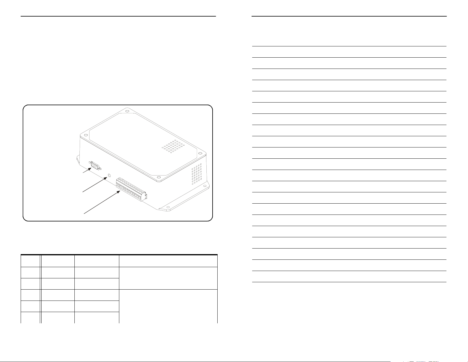
As shown in Figure 1 the Controller Module has a 12 pin and aN RS232 connector.
These provide the following three network connections:
An RS-485 network connection through the 12 pin wiring connector;
A Wiegand output also through the 12 pin connector; and,
An RS232 output.
Figure 1: Controller Module Wiring Connections
RS232 Connector
Notes
LED
12 Pin Wiring Connector
The LED in Figure 1 signals network communication and power status.
Table 1: ACR 12 Pin Wiring Connector
Pin # Label Type Description
1 V in DC Power In 500 mA @ 24 VDC ± 10%
2 GND Power ground
3 RS485+ RS485 Network • RS485 Sub-Network headed by Area
4 Gnd RS485 Ground
5 RS485- RS485 Network
Page 3 PN: 981-000293-000 R1.3
Controller Hub.
• 16 nodes, 230 kBytes/s
Page 20 PN: 981-000293-000 R1.3
Page 5

Installation Guide: Access Control Reader Installation Guide: Access Control Reader
Document Control
Document Number: 981-000293-000
Date Rev # Comments
7 Feb. 06 R1.1 Released for testing.
3 Mar. 06 R1.2 Graphics added. Installation instructions expanded.
9 Mar. 06 R1.3 Antenna tuning instructions added.
Table 1: (Continued) ACR 12 Pin Wiring Connector
Pin # Label Type Description
6 Relay N.O. Relay Normally
Open
7 Relay COM Relay Common
8 Relay N.C. Relay Normally
Closed
9 Wiegand 0 Wiegand Data 0 Standard 26-bit format (24 data bits and
10 Wiegand 1 Wiegand Data 1
11 Input Dry Contacts Pins 11 and 12 form an input for a door
12 GND Dry Contacts
The Antenna cable plugs into the connector shown in Figure 2.
Figure 2: Controller Module Antenna Connection
• 10 A 250 VAC resistive
• Protective diodes are required for an
inductive load.
2 parity bits) Wiegand output.
contact or other device.
Page 19 PN: 981-000293-000 R1.3
Antenna Connector
Antenna Description
The Antenna can be mounted indoors either on a surface or inside a wall.
A 10 ft. (3 m) power/signal cable is permanently attached to the Antenna and mates
with the Controller Module.
Page 4 PN: 981-000293-000 R1.3
Page 6

Installation Guide: Access Control Reader Installation Guide: Access Control Reader
Preferred Practices
Mounting location and positioning are very important to this unit’s correct operation.
Read and understand the information in “Access Control Reader Location” before you
begin the installation.
The Antenna is very sensitive to its mounting location while the Controller Module is
not. Additionally, you cannot extend the cable joining the Controller Module and
Antenna. So, mount the Antenna in the best location; and then install the Controller
Module in the best location within a 10 ft. (3 m) radius.
NOTE: Do not alter the Antenna cable length.
Record the location and serial number of the ACR for later inclusion in the floor plan.
Access Control Reader Location
When mounting the ACR, you must plan the best location for the Antenna and the
Controller Module.
Antenna Location Considerations
The Antenna is a tuned circuit: When selecting a mounting location, consider the
Antenna proximity to metal surfaces.
Optimally, mount the Antenna at least 6 in. away from any metal surface such as: metal
studs in the wall, metal frames around doors, air ducts, or conduit and plumbing inside
the walls.
Mount the Antenna to the right of persons approaching the controlled access point as
the microchip is usually implanted in the right arm.
Antenna Height
The ACR should accommodate people of different heights without requiring them to
stoop or stretch. Mounting the Antenna to suit the widest range of people is very
important.
Figure 3 LF Field Shape and Dimensions, shows a side view of the Antenna and the
extent of the LF Field. The field is greatest at the point labelled “Center of LF Field”.
When mounting the Antenna, the aim is to place the Center of LF Field at the same
height as the implanted microchip.
Specifications
The Access Control Reader (ACR) is a Controller Module and an Antenna joined by a
10 ft. (3 m) cable. The device reads the implantable VeriChip™ microchip. The ACR can
work as: a stand-alone reader, an Integrated access control, or part of a VeriGuard™
system.
Physical Specifications
Operating Temperature. . . . . . . . . . . . . 32° F to 122° F (0° C to 50° C)
Storage Temperature . . . . . . . . . . . . . . . -4° F to 131° F (-20° C to 55° C)
Relative Humidity. . . . . . . . . . . . . . . . . . . 0% to 90% non-condensing
Dimensions (WxHxD): . . . . . . . . . . . . . . Antenna: 7 in. x 5 in. x 1 in.
(17.8 cm x 12.7 cm x 2.5 cm)
Controller Module: 5 in. x 8 in. x 2.5 in.
(12.7 cm x 20.3 cm x 6.4 cm)
Cable Length . . . . . . . . . . . . . . . . . . . . . . . 10 ft. (3 m)
Weight:. . . . . . . . . . . . . . . . . . . . . . . . . . . . . Antenna and Cable: 1 lb. 12.3 oz. (802 g)
Controller Module: 16.3 oz. (463 g)
Electrical Specifications
Power Supply. . . . . . . . . . . . . . . . . . . . . . . 500 mA @ 24 VDC
Operating Frequency . . . . . . . . . . . . . . . 134.2 kHz
SPDT Relay . . . . . . . . . . . . . . . . . . . . . . . . . 10 A @ 250 VAC
Input . . . . . . . . . . . . . . . . . . . . . . . . . . . . . . . Dry Contact Input referenced to system ground
Network Connections
RS485 . . . . . . . . . . . . . . . . . . . . . . . . . . . . . . 230 kBytes/sec, wiring connector
RS232 . . . . . . . . . . . . . . . . . . . . . . . . . . . . . . 19.2 kBytes/sec, DB9 female
Wiegand Interface . . . . . . . . . . . . . . . . . . 24 data and 2 parity bit format, wiring connector
Indicators
Antenna: . . . . . . . . . . . . . . . . . . . . . . . . . . . LED: Green LED for power/microchip detect
indication
Buzzer: Single tone
Controller Module:. . . . . . . . . . . . . . . . . . LED: Green LED for power/network activity
indication
Page 5 PN: 981-000293-000 R1.3
Page 18 PN: 981-000293-000 R1.3
Page 7

Installation Guide: Access Control Reader Installation Guide: Access Control Reader
Wiegand
In Integrated operation and Network operation, the ACR sends microchip information
in standard 26 bit format Wiegand. This is an unacknowledged one-way
communication. Third-party software that receives this data must ensure correct
reception.
RS232
An RS232 port provides connection to a PC running a terminal emulation program
such as HyperTerminal® which is shipped with the Microsoft® Windows® operating
system.
Set the terminal as follows: one stop bit, no parity, baud rate 19200.
This is an unacknowledged one-way communication. Third-party software that
receives this data must ensure correct reception.
System Integration
In network mode, the RS485 network is connected to an Area Controller Hub
Sub-Network. Be sure to record the serial number and location of the Access Control
Reader for node location entry. Refer to the system installation manual for system
installation and commissioning.
Installation and commissioning is completed by the competent contractor or a
competent facility personnel. Following commissioning, no user adjustments are
required at the Access Control Reader during operation.
Figure 3: LF Field Shape and Dimensions
Antenna
The microchip is typically implanted
2"
Extent of
Effective LF Field
in the middle of the upper right
arm. For the best Antenna
sensitivity, align the Center of LF
Center of LF Field
Field with the microchip. This is
shown in Figure 4 Antenna
Mounting Height and Position, where
"
4
the user’s middle upper arm is
aligned with the center of the LF
field.
2"
2" = 5.08 cm
4" = 10.16 cm
Figure 4: Antenna Mounting Height and Position
Page 17 PN: 981-000293-000 R1.3
Page 6 PN: 981-000293-000 R1.3
Page 8

Installation Guide: Access Control Reader Installation Guide: Access Control Reader
Antenna Orientation
The Antenna is most effective when the long axis of the Antenna is parallel to the long
axis of the microchip.
Mount the Antenna so that the longest axis is vertical to the floor as shown in Figure 4
This mounting assumes that:
The person is standing upright; and,
The microchip is inserted with its long axis parallel to the arm.
Controller Module Location Considerations
Place the Controller Module so that it will be out of sight of the facility occupants.
Mount the Controller Module so that the panel with the wiring connector and LED is
accessible during installation.
Ensure that the Controller Module air vents are unobstructed.
Figure 5: Antenna Mounting Holes
Mounting Hole
Cable Entry
Mounting Keyhole
Mounting Keyhole
Table 5: Antenna Tuning Record
DIP Switch Number Current
1234 mA
OFF OFF OFF OFF
OFF OFF OFF ON
OFF OFF ON OFF
OFF OFF ON ON
OFF ON OFF OFF
OFF ON OFF ON
OFF ON ON OFF
OFF ON ON ON
ON OFF OFF OFF
ON OFF OFF ON
ON OFF ON OFF
ON OFF ON ON
Mounting Keyhole
Configuration
The ACR can be configured for either:
Network Mode; or,
Integrated Mode.
Network Mode
When operated in Network Mode, the ACR can work as part of a VeriGuard security
system.
Page 7 PN: 981-000293-000 R1.3
ON ON OFF OFF
ON ON OFF ON
ON ON ON OFF
ON ON ON ON
Communication Overview
The ACR sends microchip identification numbers through the Wiegand and RS232
ports and communicates via an RS485 network.
RS485
As part of a VeriChip RFID system the ACR sends the microchip identification number
to the Hub and to the application server using VeriChip’s proprietary RS485
communication protocol. The VeriChip RFID system issues commands to the ACR and
other components based upon its inputs and configuration.
Page 16 PN: 981-000293-000 R1.3
Page 9

Installation Guide: Access Control Reader Installation Guide: Access Control Reader
Figure 10: Power Supply, Ammeter, and Controller Module in Series
Controller
Module
24 VDC
DC Ammeter
2 Remove the label on the bulge of the Antenna. Behind the label you will find a
small hole that gives access to the tuning DIP switch.
3 Move all the DIP switches to the OFF position as shown in Figure 11.
Figure 11: DIP Switches in Off position
1234
O
N
4 Apply power to the ACR.
5 Notice the current measured by the ammeter. Values may range from 50 mA to
360 mA.
6 Start at the right hand #4 DIP switch. Turn it ON and OFF and record the position
which caused the greatest current and the ammeter reading. Continue to test all
the combinations of switch positions. Table 5, following, has been provided for you
to record your measurements.
7 Select the switch combination that causes the greatest current.
8 If two settings produce the same values, use either setting.
9 You have now tuned the Antenna for the best possible performance in its current
location. You must now re-check its performance using a microchip. If the
detection zone is large enough, replace the label covering the tuning DIP switch.
End of Procedure
All three communication channels are active in Network mode. This allows the ACR to
output microchip identification numbers to third party systems through both the
RS232 and Wiegand ports while continuing to function as part of the VeriGuard
security system on the RS485 network.
In network operation, the ACR is configured through the VeriChip application.
Integrated Mode
When operated in Integrated Mode the ACR can automatically monitor a single access
point. When the ACR reads a VeriChip implantable microchip, it transmits the
microchip identification through the RS-232 and Wiegand ports.
Selecting the operating mode is the first step of the installation procedure below.
Installation
Installation of the ACR consists of several steps. The first step is to select the operating
mode.
Selecting Integrated or Network Mode
The operating mode can be selected using two jumpers: J4 and J5. Both jumpers are
found in the middle of the Controller Module circuit board. Both jumpers have two
pins and a single jumper which can be used to connect the pins.
To select Integrated Mode or Network Mode:
1 Open the Controller Module by removing the four screws in the top of the case.
Locate the jumpers.
2To select Integrated Mode: Connect both J4 and J5 with jumpers.
3To select Network Mode: Remove the jumpers from J4 and J5. Store the jumpers
by placing them on only one pin of each pair.
4 Close the Controller Module.
End of Procedure
Surface Mounting on a Wall
To mount the ACR to a wall surface:
If, after tuning the Antenna, the ACR detection zone is still not adequate, you must
consider modifying the current location; or, selecting another location for the ACR.
Modifying the current location could include:
Moving the Antenna cable further from the Antenna.
Removing any metallic objects near the Antenna.
If you move the Antenna to another location, you may need to retune the Antenna.
Page 15 PN: 981-000293-000 R1.3
1 Once you have chosen a location for the Antenna, use the supplied mounting
template to mark the location of the four mounting holes and one cable entry
hole.
2 Drill the appropriate size holes for #8 screws (4.17 mm) and suitable mounting
hardware for the wall material.
3 Drill the appropriately sized hole for the Antenna cable.
Page 8 PN: 981-000293-000 R1.3
Page 10

Installation Guide: Access Control Reader Installation Guide: Access Control Reader
4 Feed the cable connector through the hole first and draw the cable up to the
Controller Module. Do not connect the Controller Module at this time.
5 Mount the Antenna to the wall using mounting hardware suitable for the wall
material.
NOTE: Do Not allow the cable to hang within 4 in.
(10.2 cm) of the Antenna back.
Figure 6: Incorrect Cabling
Wall
Antenna
Cable
Do Not Do This:
Do Not Do This:
Do Not Do This:Do Not Do This:
Do Not allow cable to hang
within 4 in. (10.2 cm) of the
Antenna back.
Corridor
Wall
Interior
7 The cable may be loosely coiled. Tightly coiling the cable may damage it. Use a
maximum of three turns over the entire cable length.
6 Route the cable away from the Antenna.
Ensure the cable does not kink and does
not contact any electrical wires or sharp
surfaces.
Figure 6 shows an incorrect method of
cable routing. The metal shield of the
cable will detune the Antenna when the
cable and Antenna are within 4 in. of
each other.
Figure 7 shows two correct methods of
routing the cable. The method on the
right is better than the method on the
left as it draws more of the cable further
from the Antenna.
Figure 8 is a variation of Figure 7. In
Figure 8 the cable is led up and then in a
horizontal direction either to the left or
right. This again draws the cable away
from the Antenna.
Use the following procedure to test the detection zone size.
To test the detection zone size:
1 Bring a VeriChip™ implantable microchip slowly towards the surface of the
Antenna. When the microchip signal is first acquired, the Antenna LED will flash
and the Antenna buzzer will beep. When the signal is acquired, note the distance
between the microchip and the Antenna.
2 Move the microchip a few feet away from the Antenna and wait for more than
12 seconds. Repeat Step 1.
Once the microchip signal has been acquired, the ACR will not indicate signal
acquisition again until the microchip is out of range for more than 12 seconds.
3 Repeat the above steps several time to find the size of the LF Field.
End of Procedure
Tools
You will need:
an ammeter capable of reading DC milliamperes
a small tipped tool such as a small screwdriver
a power source for the ACR. This must supply 500 mA @ 24 VDC.
Tuning Overview
Tuning increases Antenna efficiency and creates a larger LF Field. The increase of
Antenna efficiency is measured by the ACR current draw. When the ACR current peaks,
the Antenna is tuned.
Tuning is controlled by four small on-off DIP switches. You must select the switch
combination that causes the greatest current draw.
To Tune the ACR:
1 Mount the Antenna in location. Arrange the Antenna cable in its final position.
Connect the Antenna cable to the controller. Place an ammeter capable of
measuring DC mA in series between the power supply and the Controller Module.
See Figure 10.
8 Wire the Controller Module as described in Table 2.
9 Connect the Antenna cable to the Controller Module.
10 If you have not already done so, record the location and serial number of the ACR
for later inclusion on the floor plan.
End of Procedure
Page 9 PN: 981-000293-000 R1.3
Page 14 PN: 981-000293-000 R1.3
Page 11

Installation Guide: Access Control Reader Installation Guide: Access Control Reader
Verifying Operation
Verify power and network communications by observing the Controller Module LED.
See Table 3.
Table 3: Controller Module LED and Status
LED Status
Slow dim flashing Power on but without network communications
Fast bright flashing Power on with network communications
Verify ACR operation at the Antenna by observing the Antenna LED and buzzer. See
Tab le 4.
Table 4: Antenna LED and Buzzer; and ACR Operation
LED Buzzer ACR Operation
ON ~ ACR power on, normal operation.
Bright Flash Beep A microchip enters the LF field. The ACR signals
that the microchip has arrived in the field and that
the ACR has acquired its unique identification
number.
The microchip must be outside the field for 12
seconds or more before the ACR will again signal
that the microchip has entered the field; and,
acquire the microchip identification number.
Flashing ~ A microchip is within the LF field. The ACR is
maintaining communication with the microchip.
Figure 7: Correct Cabling
Wall
Antenna
Cable
Strap
Keep this
curve
gentle.
Cable
Wall
Antenna
The Better Way The Best Way
Corridor
Wall
Interior
Figure 8: Variation of Correct Cabling
Cable
Wal l
More than 4 in. (15.2 cm)
Corridor
Wall
Interior
Cable
AntennaAntenna
Tuning the ACR
The ACR will work in most installations without tuning. However, tuning features have
been provided to accommodate the widest possible range of installations.
When do you need to tune the ACR?
You need to tune the ACR when it is installed near a metallic object or structure and
the range of the LF Field does not provide a minimal operational microchip detection
zone.
The microchip detection zone is dependent on the size of the LF Field. The largest
possible LF Field extends approximately 3 in. to 4 in. from the Antenna surface
depending on site conditions. If the detection zone is less than this, it is possible that
tuning the Antenna may increase the LF Field size. However, Antennas are shipped
tuned. So, if your LF Field size is adequate, there may not be any advantage to tuning.
Page 13 PN: 981-000293-000 R1.3
A Variation of the
Best Way
Corridor
Wal l
Interior
Side View
Front View
(Wall is not shown.)
Page 10 PN: 981-000293-000 R1.3
Page 12

Installation Guide: Access Control Reader Installation Guide: Access Control Reader
Mounting the Antenna Inside a Wall
When the Antenna must be located inside a wall, consider the following:
The detection zone will be smaller due to the wall thickness. You may not have a
large enough detection zone on both sides of the wall. For example, Figure 9 shows
an Antenna mounted inside a 4 in. (10.16 cm) wall. In the figure, only about 1 in.
(2.54 cm) of the LF field extends into the corridor on the right side of the wall.
The wall material must not contain metal that would block the LF Field.
The Antenna must be mounted vertically to ensure an even detection zone.
You will need to construct a mounting surface inside the wall. Do not suspend the
Antenna by the cable.
Figure 9: ACR Mounted Inside a Wall
Antenna
4
Corridor
To mount the Antenna inside the wall:
Wall
Interior
4
3
Extent of
Effective RF Field
Wall
All dimension s in inches.
4 in. = 10.16 cm
3 in. = 7.62 cm
5 Use Table 2 to wire the Controller Module.
6 Before closing up the wall, test and confirm correct operation of the ACR.
End of Procedure
Wiring the Access Control Reader
Wire the ACR using the 12 pin wiring connector as described in Table 2. (This table
from page 3 has been repeated for your convenience.) See Figure 1 for the location of
the wiring connector.
Table 2: ACR 12 Pin Wiring Connector
Pin # Label Type Description
1 V in DC Power In 500 mA @ 24 VDC ± 10%
2GND Power ground
3 RS485+ RS485 Network • RS485 Sub-Network headed by Area
4 Gnd RS485 Ground
5 RS485- RS485 Network
6 Relay N.O. Relay Normally
Open
7 Relay COM Relay Common
8 Relay N.C. Relay Normally
Closed
9 Wiegand 0 Wiegand Data 0 Standard 26-bit format (24 data bits and
10 Wiegand 1 Wiegand Data 1
11 Input Dry Contacts Pins 11 and 12 form an input for a door
12 GND Dry Contacts
Controller Hub.
• 16 nodes, 230 kBytes/s
• 10 A 250 VAC resistive
• Protective diodes are required for an
inductive load.
2 parity bits) Wiegand output.
contact or other device.
1 Choose locations for the Antenna and the Controller Module. Allow room on
either side of the Antenna for both the Antenna bulge and the cable.
2 Using the supplied mounting template, construct a secure mounting surface
inside the wall for the Antenna.
3 Mount the Antenna using #8 screws (4.17 mm).
4 Follow the instructions in the previous section for cable routing.
Page 11 PN: 981-000293-000 R1.3
Page 12 PN: 981-000293-000 R1.3
 Loading...