


Installation Manual
for
Controllers and Receivers
June, 1999
© Copyright 1999, EXI Wireless Systems Inc. All rights reserved.

EXI HALO Installation Manual Rev 2.0
Revisions
Date Changed by Description
6/9/99 Zahir Abji First Release
6/17/99 Zahir Abji System Wiring section added and Halo
Wiring Diagram corrected
NOTICE: This equipment has been tested and found to comply with the limits of a class B digital device, pursuant to
Part 15 of the FCC rules. These limits are designed to provide reasonable protection against harmful interference in a
residential installation. This equipment generates, uses and can radiate radio frequency energy and, if not installed and
used in accordance with the instructions, may cause harmful interference to radio communications. However, there is
no guarantee that interference will not occur in a particular installation. If this equipment does cause harmful interference to radio or television reception, which can be determined by turning the equipment off and on, the user is encouraged to try and correct the interference by one or more of the following measures. (1) Reorient or locate the receiving antenna. (2) Increase separation between the equipment and the receiver. (3) Connect the equipment into an
outlet on a circuit different from that to which the receiver is connected. (4) Consult the dealer or an experienced
radio/TV technician for help.
NOTICE: Operation is subject to the following two conditions: (1) This device may not cause interference, and
(2) This device must accept any interference, including interference that may cause undesired operation of the
device.
Any changes or modifications not expressly approved by the manufacturer could void the user’s authority to operate the equipment.
EXI Wireless Systems Inc. Page 2 June, 1999

EXI HALO Installation Manual Rev 2.0
LIMITED WARRANTY
EXI Electronic Systems a division of Diversity Products Ltd. (collectively, “EXI”) hereby warrants the product(s) accompanying this limited warranty (the “Product(s)”) to be free of defects in materials and workmanship
for a period of two years (excluding any batteries that may be added to or used in conjunction with the Products(s)) from the date of delivery of the original purchase of the Product(s) subject to the limiting conditions set
forth below, provided that EXI has received notification of such defects no later than 30 days after expiration of
the applicable warranty period and provided further that EXI has received a fully completed registration card
(below) within 30 days from the date of original purchase of the Product(s).
The responsibility of EXI under this warranty is and shall be limited to repairing or replacing the Product(s) or
any part thereof determined by EXI in its sole discretion to be defective in workmanship or material.
The installation of the Product(s) shall be deemed as acceptance by the original purchaser and any subsequent
purchaser of the Product(s) (collectively the “Purchaser”) of the terms set out in this limited warranty including
the following further limiting conditions:
(a) EXI shall not be responsible for any repair or replacement of any Product(s) which has been found, upon
inspection, to have been subjected to abuse, misuse or negligence, or any damage attributable to accident, lightning, power surge, brown-out, leaking, damaged or inoperative batteries or to have been installed, altered or
repaired contrary to factory designated procedures without the prior written consent of EXI;
(b) It is understood, and the Purchaser agrees further to so inform any user of the Product(s) that the Product(s)
is not, nor can it be, infallible in the detection of wandering patients, the prevention of infant abduction, the prevention of theft of assets or any other contemplated use of the Product(s). The Purchaser will warn all users
and acknowledges on it’s own behalf that it has read and understands the above-mentioned limitations of
the Product(s). The Purchaser further acknowledges that the Product(s) are solely intended to provide an addi-
tional safeguard in notifying staff and accordingly do not guarantee the prevention of wandering patients or the
attempted abduction of an infant or the theft of assets;
(c) It is further agreed by the Purchaser that the Purchaser has received no additional promises or statements of
fact from EXI or its agents relative to the Product(s) upon which the Purchaser might have relied in purchasing
the Product(s);
(d) The warranty set out above excludes and is in lieu of all other express or implied warranties, conditions or
obligations, and no person is authorized to give any further representation or warranty or assume any further
obligation on behalf of EXI. Although the Purchaser may have other rights, as they may vary from State to State
or Province to Province, where it is legally possible to do so any statutory warranty is hereby expressly excluded. The warranty is subject to the domestic laws of the Province of Manitoba, Canada and the Purchaser
agrees to attorn to the jurisdiction of the courts of competent jurisdiction in the Province of Manitoba; and
(e) EXI shall not be liable for any damages, whether direct or, indirect, incidental, consequential or arising out
of contact or tort with the sole exception of the warranty set out above and any rights expressly created by applicable statute.
THIS WARRANTY IS VALID ONLY IN THE USA AND CANADA
EXI Wireless Systems Inc. Page 3 June, 1999

EXI HALO Installation Manual Rev 2.0
Table of Contents
1. INTRODUCTION..............................................................................................................................................5
1.1. INTENDED AUDIENCE...................................................................................................................................5
1.2. SYSTEM OPERATION..............................................................................................................................5
2. DECISIONS TO MAKE PRIOR TO INSTALLATION.............................................................................6
2.1. SYSTEM WIRING...................................................................................................................................... 6
2.2. CONTROLLER CONFIGURATIONS...................................................................................................... 7
2.3. LOCATION FOR SRA EXCITER ANTENNAS......................................................................................7
2.4. KEYPAD OR PINPAD? ............................................................................................................................ 9
2.5. LOCATING THE RECEIVER ANTENNA..............................................................................................9
3. INSTALLATION PROCEDURES...............................................................................................................10
3.1. INSTALLING CONTROLLERS..............................................................................................................10
3.1.1. PREPARE CONTROLLER FOR FIELD SET UP.........................................................................10
3.1.2. TEST CONTROLLER AND SET UP FIELDS...............................................................................11
3.1.3. FINALIZE CONTROLLER INSTALLATION.................................................................................12
3.1.4. SET CONTROLLER SWITCHES FOR NORMAL OPERATION.................................................13
INSTALL RECEIVERS........................................................................................................................................15
3.3. TESTING TIC ALARM COVERAGE AROUND THE BUILDING ....................................................15
3.4. CONNECTING TO THE HOST COMPUTER ......................................................................................16
4. WEIGAND OUTPUT SPECIFICATION....................................................................................................19
Figure 1 - Controller Operation...............................................................................................................................5
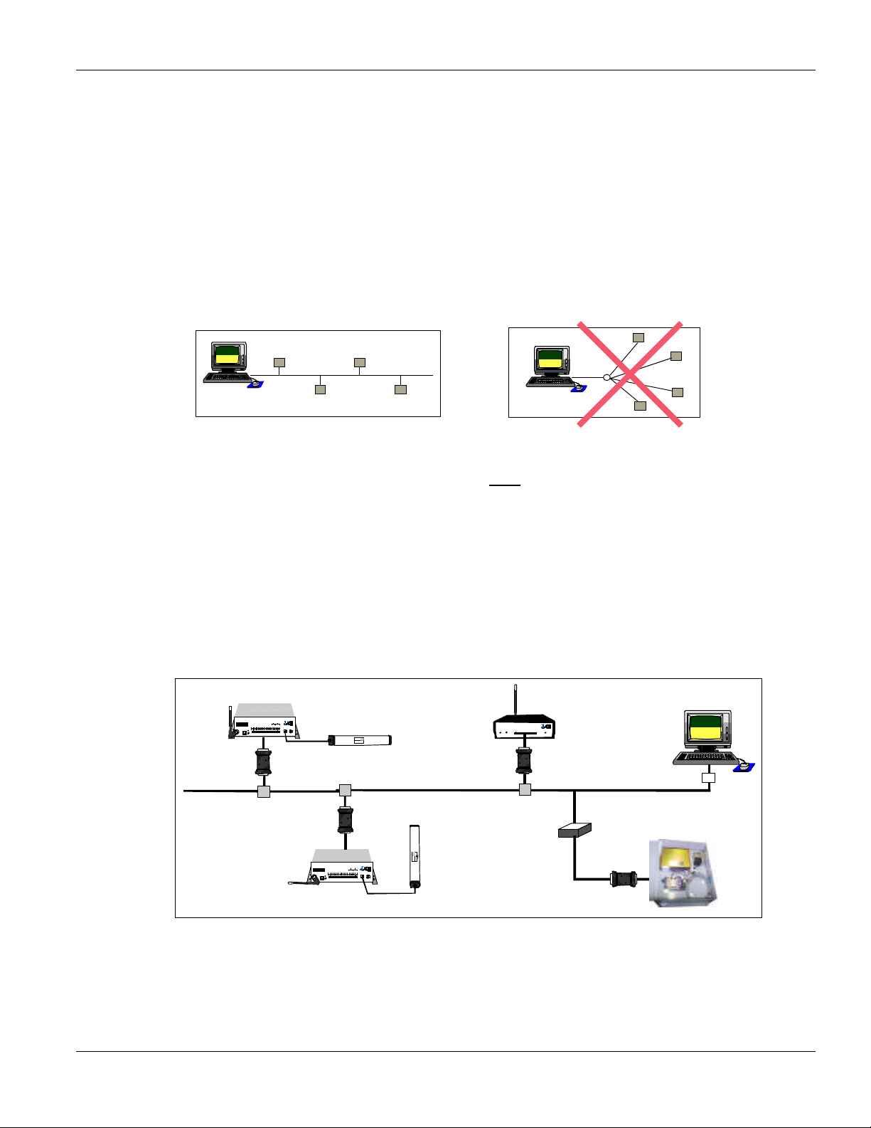
Figure 2 - "Bus" Topology Figure 3 - "Star Topology........................................................................................6
Figure 4 - Typical HALO Configuration..................................................................................................................6
Figure 5 – Antenna Field...........................................................................................................................................8
Figure 6 - HALO Controller Typical Hook-up Diagram......................................................................................10
Figure 7 - Securing the Exciter Antenna Cable .....................................................................................................12
Figure 8 – Controller Switch Identification...........................................................................................................13
Figure 9 – HALO Receiver.......................................................................................................................................15
Figure 10 – HALO Receiver Threshold and Operating Voltage Setting.............................................................15
Figure 11 – HALO Network with Host Computer..................................................................................................16
Figure 12 – Sketch of RIM.......................................................................................................................................16
Figure 13 – HALO System Grounding...................................................................................................................17
Figure 14 - Halo Wiring Diagram..........................................................................................................................18
EXI Wireless Systems Inc. Page 4 June, 1999

EXI HALO Installation Manual Rev 2.0
1. INTRODUCTION
1.1. Intended Audience
This manual serves as a guide for Installers of the HALO system. The major components of the system
are described, as well as the system’s intended functionality, so as to gain familiarity with its operation
prior to installation. In order to successfully install and commission the system, it is absolutely critical
to understand the capabilities of the system and its components prior to installation.
The function of the HALO system is to monitor areas within a building for the presence of HALO
Tags. A Tag is sensed when it either enters an RF Field that is set up using the EXI HALO Controller
(referred to as a Tag in Field or TIF), or when the Tag initiates an alarm signal (referred to as Tag Initiated Communications, or TIC).
1.2. SYSTEM OPERATION
The EXI HALO system uses Radio Frequency waves for communications between the HALO system
components and the Tags. The HALO Controller continuously emits a 307 kHz RF frequency via the
Exciter Antenna, setting up a field in its local area. When a Tag enters this field, a Radio Receiver
within the Tag senses the 307 kHz RF field and transmits its identification information to the HALO
Controller using a low level Radio Signal at frequency of 434 MHz.
RX
Antenna
434 MHz
HALO Controller
FCC ID# HE7MAX
+24V DC Input
System Ground
+12V Ou 200 ma
System Ground
Weigand 0/Data
Weigand 1/Gnd
System Ground
MagOut 24V 200 ma
Door Switch In
System Ground
RECEIVE
ANTENNA
Made in Canada . . with care
Power
RBC
OFF ON
1 2 3 4 5 6 7 8 9 10 11 12 13 14 15 16 17 18 19 20
Alarm In
Transponder
Figure 1 - Controller Operation
Unlock In
Override In
Relay #1 Relay #2
Strobe In
N.O
COM
N.C.
N.O
COM
N.C
TRANSMIT OUTPUT
SEA #1
by
Controller
SEA #2
ROAM II/TAGRRR
SEA-M
1118
Made in Canada
EXI ELECTRONIC SYSTEMS
Winnipeg, Manitoba (204) 788-1696
PRODUCT
MODEL NO.
SERIAL NO>
307 KHz
SRA
Exciter
Antenna
EXI Wireless Systems Inc. Page 5 June, 1999
EXI HALO Installation Manual Rev 2.0
2. DECISIONS TO MAKE PRIOR TO INSTALLATION
2.1. SYSTEM WIRING
The HALO network is based on the RS-485 electrical interface standard, which is 2-wire multi-node
bus. The EXI HALO elements are designed such that many more than the RS-485 limit of 32 Drivers
and 32 Receivers can be co-exist on the same network. The baud rate used in the HALO system is
57,600 bps, and therefore in order to avoid data corruption it is important to ensure that a clean signal
is always present. Using the right type of cable, network topology, and not exceeding total cable length
are critical factors in ensuring that the system will operate reliably.
Figure 2 - "Bus" Topology Figure 3 - "Star Topology
Cable capacitance is a large factor in determining the quality of the signal on the network, and EXI recommends that cables with capacitance of greater than 15 pf per foot should be avoided. The network
should be constructed using a “multi-drop bus” type topology, avoiding any “star” type configuration.
The system is designed to operate with up to 4,000 ft of cable with the recommended topology and cable. The total cable length varies depending upon the cable capacitance and effective resistance, topology, and number of devices on the network. If the estimated total cable length is greater than 4,000 ft, a
RS-485 Repeater will be required to ensure that the system works reliably, or works at all.
It is also recommended that a Repeater be used to isolate HALO Elevator Controllers from the main
system to minimize noise pick-up and loading of the system. Cables used in Elevator shafts should be
stranded and not solid, and should be resilient enough to withstand the continuous flexing that it will
experience for many years in the elevator shaft.
Whip
Antenna
R2 RECEIVER
POWER
Made in Canada . . with care
DATA
COMM.
12/24 VDC
1 2 3 4 5 6 7 8 9 10
TAP
Receiver 1
GROUND
DATA 0
DATA 1
N/O 1
COM 1
N/C 1
N/O 2
COM 2
N/C 2
RELAY
RIM
RS-485
Repeater
HALO Network
Elevator Controller
RIM
PC
Terminator
Whip
Antenna
Controller 1
FCC ID# HE7MAX
Relay #1Relay #2
+24V DC Input
System Ground
+12V Ou 200 ma
System Ground
Weigand 0/Data
Weigand 1/Gnd
System Ground
MagOut 24V 200 ma
Door Switch In
System Ground
Unlock In
Override In
Strobe In
N.O
COM
N.C.
N.O
COM
Alarm In
RECEIVE
ANTENNA RBC
Power
1 2 3 4 5 6 7 8 9 10 11 12 13 14 15 16 17 18 19 20
OFF ON
Made in Canada . . with care Controller
RIM
TAP
Whip
Antenna
by
N.C
TRANSMIT OUTPUT
SEA #1 SEA #2
Exciter
Antenna
TAP
RIM
FCC ID# HE7MAX
Relay #1Relay #2
+24V DC Input
System Ground
+12V Ou 200 ma
System Ground
Weigand 0/Data
Weigand 1/Gnd
System Ground
MagOut 24V 200 ma
Door Switch In
System Ground
Unlock In
Override In
Strobe In
N.O
COM
N.C.
Alarm In
RECEIVE
ANTENNA
RBC
Power
1 2 3 4 5 6 7 8 9 10 11 12 13 14 15 16 17 18 19 20
OFF ON
Made in Canada . . with care Controller
Controller 2
SERIAL NO>
1118
MODEL NO.
SEA-M
PRODUCT
ROAM II/TAGRRR
Made in Canada
Winnipeg, Manitoba (204) 788-1696
EXI ELECTRONIC SYSTEMS
RS485 Bus
Exciter
Antenna
Winnipeg, Manitoba (204) 788-1696
PRODUCT
MODEL NO.SERIAL NO>
Made in Canada
ROAM II/TAGRRR
SEA-M
by
N.O
COM
N.C
TRANSMIT OUTPUT
SEA #1 SEA #2
1118
Figure 4 - Typical HALO Configuration
EXI Wireless Systems Inc. Page 6 June, 1999
 Loading...