

Page 1

User Manual
December 2000
March 2000, Revision 5.0, Added FCC Regulations
December 2000, Revision 6.0, Added new features from HALO™ software version 3.1
© Copyright 2000, EXI Wireless Systems Inc., All rights reserved.
Revision 6.0
Page 2

EXI HALO User Manual 980-000002-000
Table of Contents
ABOUT THIS DOCUMENT..........................................................................................................................3
1. SYSTEM INTRODUCTION..................................................................................................................5
1.1. S
1.2. T
1.3. C
2. USER LEVEL FUNCTIONS..................................................................................................................8
2.1. A
2.2. D
2.3. D
2.4. S
2.5. “N
2.6. I
3. SUPERVISOR LEVEL FUNCTIONS.................................................................................................19
3.1. A
3.2. E
4. ACTIVITY LOG MANAGEMENT.....................................................................................................21
4.1. A
4.2. N
4.3. A
4.4. B
YSTEM COMPONENTS
ERMS USED IN THIS DOCUMENT
OMPUTER DISPLAY CONVENTIONS
DMITTING A PATIENT
ISCHARGING OR EDITING A PATIENT
ISABLING A TAG TEMPORARILY
ILENCING AND ACCEPTING ALARMS
URSE SAVER” AND “LOITERING
MPROPERLY STORED TAGS
CCESSING SUPERVISOR LEVEL
XITING SUPERVISOR LEVEL
CTIVITY LOGS
AVIGATING THE ACTIVITY LOG
DDING A SUPERVISOR ANNOTATION TO AN ALARM
ACKING UP ACTIVITY LOGS
................................................................................................................................21
......................................................................................................................5
........................................................................................................5
..................................................................................................6
.......................................................................................................................8
..............................................................................................11
.....................................................................................................13
..............................................................................................15
EATURES
” F
.................................................................................17
..............................................................................................................17
.......................................................................................................19
............................................................................................................20
.......................................................................................................22
...........................................................................................................23
........................................................................22
5. MANAGING TAGS..............................................................................................................................24
5.1. T
5.2. A
5.3. D
5.4. D
5.5. U
5.6. E
5.7. C
5.8. L
AGS
...............................................................................................................................................24
DDING A NEW
ELETING A
ISABLING A
NASSIGNING A
DITING A
HANGING A TAG’S EXPIRY DATE
OCATE A TAG
P-T
AG TO THE SYSTEM
P-T
AG FROM THE SYSTEM
P-T
............................................................................................25
.............................................................................................26
P-TAG.........................................................................................................................27
P-TAG....................................................................................................................27
AG RECORD
...............................................................................................................28
...................................................................................................28
.................................................................................................................................29
6. MANAGING SYSTEM USERS...........................................................................................................30
6.1. A
6.2. D
6.3. D
6.4. E
DDING A NEW USER TO THE SYSTEM
ELETING A USER FROM THE SYSTEM
ISABLING A SYSTEM USER
DITING A SYSTEM USER’S ACCESS LEVEL
..............................................................................................................32
...............................................................................................31
...............................................................................................32
........................................................................................32
7. PRINTING LOGS................................................................................................................................33
8. MANAGING ALARM ANNOTATIONS............................................................................................34
8.1. A
8.2. D
8.3. E
DDING AN ANNOTATION
ELETING AN ANNOTATION
DITING AN ANNOTATION
...............................................................................................................35
.............................................................................................................35
...............................................................................................................35
9. SHUTTING DOWN AND RESTARTING THE SYSTEM................................................................36
9.1. S
9.2. R
HUTTING DOWN
ESTARTING THE SYSTEM
.............................................................................................................................36
.................................................................................................................36
APPENDIX A - LIMITED WARRANTY....................................................................................................37
APPENDIX B - FCC REGULATIONS .......................................................................................................38
APPENDIX C - SYSTEM MAINTENANCE...............................................................................................39
EXI Wireless Systems Inc. 2 December 2000
Revision 6.0
Page 3

EXI HALO User Manual 980-000002-000
ABOUT THIS DOCUME NT
Intended Audience
This manual is intended for system users (typically duty nurses), team leaders, and supervisory level users who manage the system and the system users.
Scope
This manual will provide step-by-step instructions for users and supervisors who administer the usage of
the system. The HALO™ system features a very simple user interface that guides the user through each
step.
About the Halo Infant Protection System
• HALO™ is a premium infant protection system.
• HALO™ works in conjunction with the EXI P-tag patient transponder that is capable of sensing
if it has been removed from the infant.
• HALO™ is an electronic system, which, in conjunction with staff diligence, creates a secure
perimeter to deter infant abductions.
• HALO™ will detect if an infant is near a controlled exit and invoke countermeasures.
• The system will identify the infant, the location and the time.
• Alarms must be accepted by staff using password access to the system.
• The system maintains a log of all activity.
Access Levels
The HALO™ system has three separate access levels:
• User
• Team Leader
• Supervisor
Level Password
required
User Yes Admit Patients
Discharge Patients
Accept/Silence alarms
Toggle between floor plans
Team Leader Yes All user functions
Temporarily Disable Patient
Functions Access Management
Access controlled by Supervisor level
users
Access controlled by Supervisor level
users
EXI Wireless Systems Inc. 3 December 2000
Revision 6.0
Page 4
EXI HALO User Manual 980-000002-000
Supervisor Yes All team leader functions
Manage user list
Assign usernames and passwords
View and annotate activity logs
Add/Delete tags from fleet
Add alarm annotations
Initiate System Data Backups
Print logs
Exit the
HALO™
System Conventions
Each user in the system has a unique identity (username) and password. The Supervisor assigns both the
username and password. It is suggested that both be kept between 4-8 characters to provide sufficient
security and allow users to easily enter and remember their system access codes. For example: a user
named Barbara Smith would have a username such as bsmith or barbs. Note that that each user must
have a unique name.
The system prompts the user for any text entry such as usernames or infant names, etc. To move from one
field to the next, the user may press Tab key on the keyboard or place the mouse cursor over the field and
Click the left button.
System Support
The first Supervisor is setup by the
installing dealer. This Supervisor may
add more assigned supervisory access.
system
For system service or support contact your installing dealer
Or contact:
EXI Wireless Systems Inc.
Suite 100-13551 Commerce Parkway
Richmond, BC V6V 2L1
Canada
Ph: 1-800-667-9689
Fax: 604-207-7760
Website: www.exi.com
EXI Wireless Systems Inc. 4 December 2000
Revision 6.0
Page 5

EXI HALO User Manual 980-000002-000
1. SYSTEM INTRODUCTION
1.1. System Components
HALO™ Software:
Controllers:
Receivers:
Transponders:
Primary user interface that assists in the assignment and tracking of Transponders,
and displays alarms and other activities in graphical format. It also stores and allows printing of all system events that have been logged.
Controls an egress point and reports any Tag presence at the egress point to the
computer. Depending on sys tem configuration, c ontrollers may control door locks
and local alarms, and allow keypad input for door bypass. They may also provide a
“Nurse Saver” and “Loiter” feature. The “Nurse Saver” feature eliminates nuisance
alarms by not setting off an alarm when the presence of a Tag is detected and the
door is se nsed as closed. In the event that the door is open, or is opened when the
Tag is at the egress point, the system will alarm. The “Loiter” feature sounds an
alarm if a Tag detected at a door rema ins at that door for a peri od of time, regardless of the fact that the door may be sensed as closed.
Controllers will also detect a “Tag off body” condition in its area, as does a Receiver.
Detects “Tag off body” condition when a Tag is removed from a patient, and reports
this activity to the computer.
Also referred to as “Tags”, these devices are attached to the patient. Tags initiate
two different kinds of alarm conditions as follows:
TIC - Tag-initiated-Communications:
This alarm is initiated in the event that a Tag is removed from a patient. This
occurs when the Tag can no longer sense the body of the patient.
TIF - Tag-in-field Communications:
This alarm is initiated when a Tag enters an area protected by a Controller.
The Controller’s antenna(s) emit a constant field of radio waves that is
picked up by the Tag when in the proximity of the Controller. The Tag reports its presence to the Controller, and therefore the system, when it senses
this field of radio waves.
1.2. Terms used i n t hi s document
The following terms are used to help explain user functions in this document:
-
for example, to complete a function place the mouse pointer over the button then
click the left mouse button.
This term is usually used to highlight data, for example when that data is to be changed, or deleted..
- Θ Names of keys are shown as the physical keys on a keyboard.
means to press a key on the keyboard
Press
means click the left mouse button once. This term is usually used for an action button,
Click
means you position the mouse pointer in a data area and click the left mouse button.
Select
EXI Wireless Systems Inc. 5 December 2000
Revision 6.0
Page 6
EXI HALO User Manual 980-000002-000
- Names of dialog boxes, screens, and field titles in forms are bolded or
shown graphically.
- Names of buttons are shown as on screen.
1.3. Computer Display Conventions
The computer displays various types of information, which is color -coded, to differentiate between the
Supervisor and Use r mode s. In addi tion, the “Icons” that displ ay the l ocations of the various system
components such as the Controllers and the Receivers, and the on-screen “buttons” may also change
color to indicate their status.
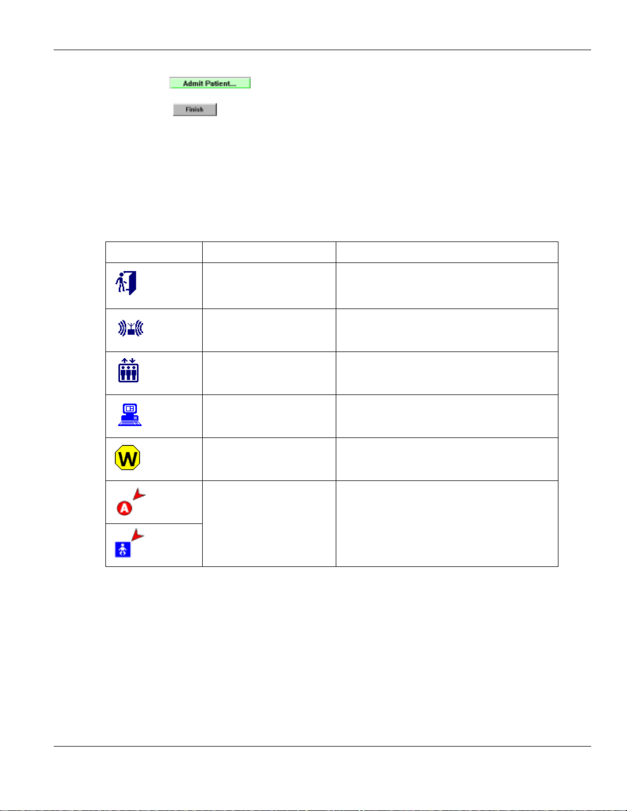
The table below shows the various icons, and alarm conditions.
Icon Name Description
The controllers are located near egress points, such
Controllers
as doors. This icon will flash red if there is a
communication problem.
Receivers
Elevators
Console
Pre-alarm
Alarm Condition
Receivers can be placed anywhere, and will only
detect off-body TIC alarms.
Elevators are controllers which detect TIC or TIF
alarms near an elevator.
The console is the computer that runs the HALO™
softw ar e.
Controllers or Receivers will flash these two icons
when they receive a TIC, a TIF, or a loiter alarm.
EXI Wireless Systems Inc. 6 December 2000
Revision 6.0
Page 7
EXI HALO User Manual 980-000002-000
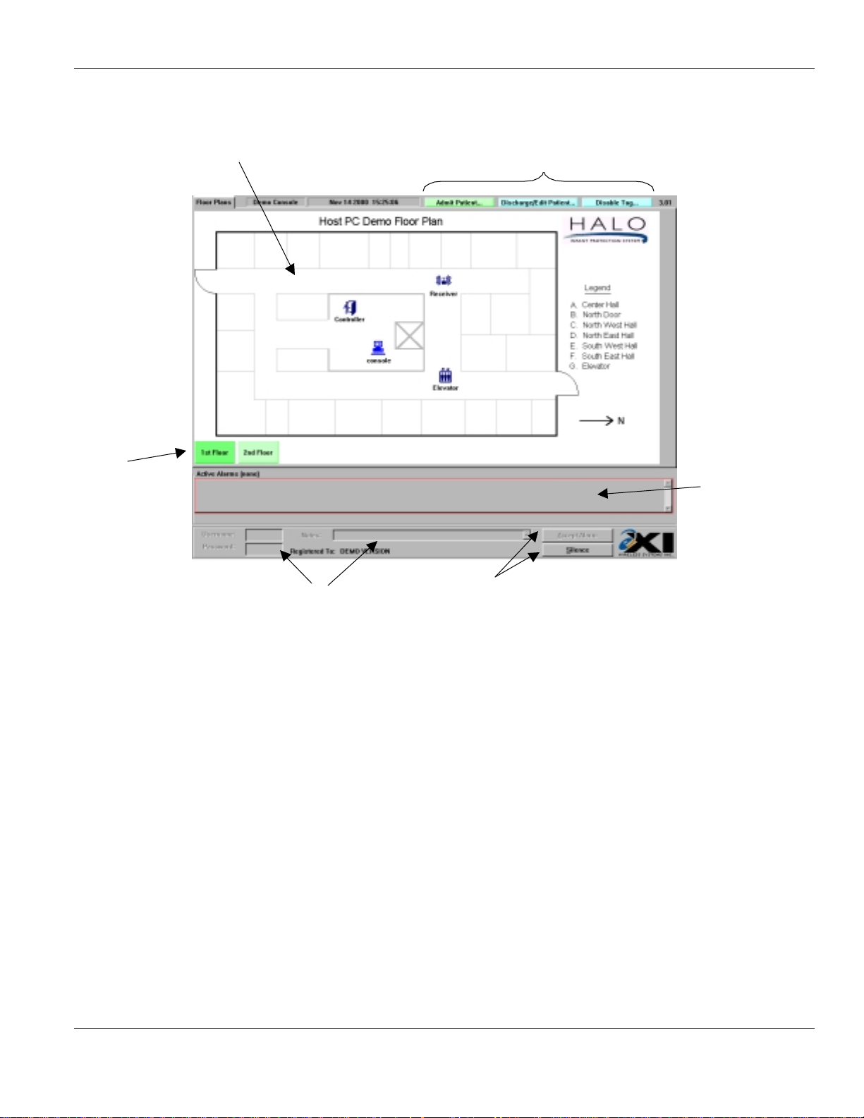
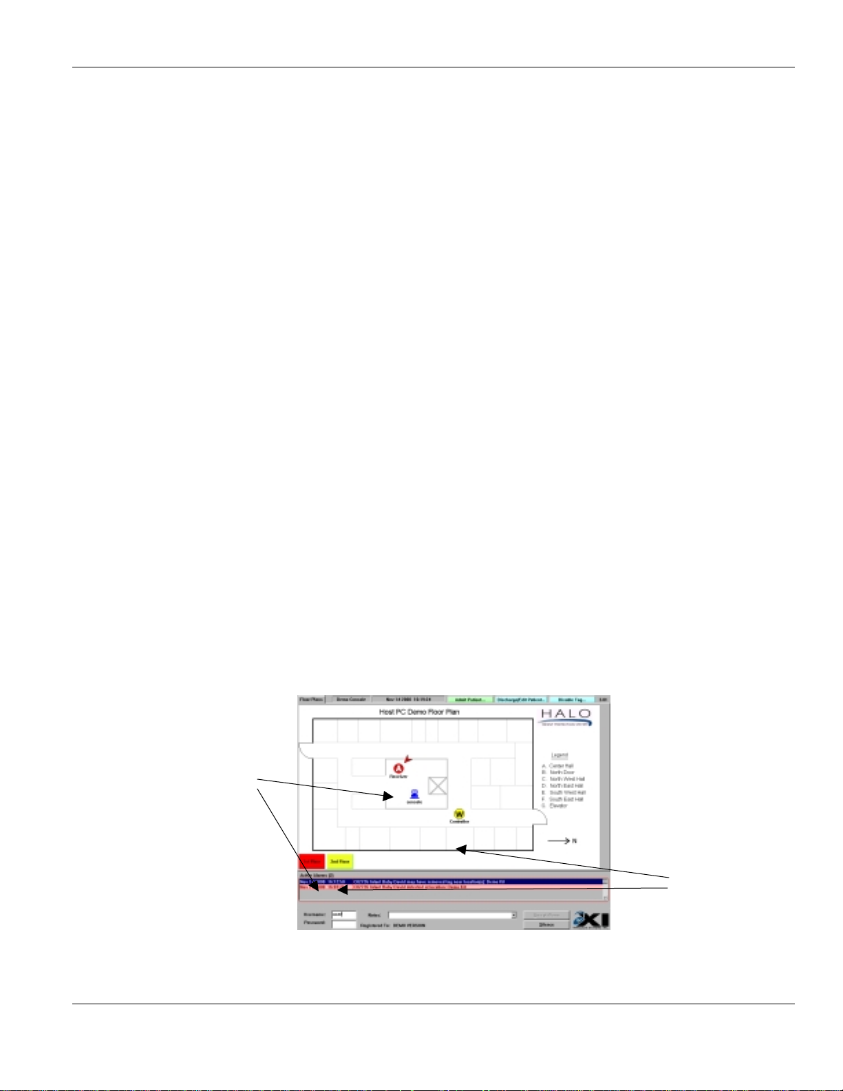
The figure below shows a typical user screen and identifies its components.
1
3
2
4
Walk around:
1.
This is the fl oor plan area. It shows the positions of all control lers, recei vers, elevators, and consoles that are installed in your system.
2.
Floor navigation buttons. Clicking on the desired floor will cause that floor to be displayed on the
screen. The buttons will change color depending on the alarms have occurred on each floor:-
3.
These are the action buttons. From here you can
Team leaders may also
4.
This is the list of
played in this window. In order to
line with alarm, and click the left mouse button to select. When the alarm is selected it will turn
blue.
5.
Once an alarm has been selected from the
fields will become active. In order to accept an alarm, these three fields must be filled in.
6.
These are the
are filled in, the
accept the alarm. The
5
Green:
Blue:
Yellow:
Red:
Normal
Indicates that the cursor is positioned over button
Indicates Pre-alarm condition on floor
Alarm condition on this floor
Disable a Tag
Act ive Ala rms
Accept Alarm
Accept Alarm
Silence
and
button is always available after selecting an alarm from the list.
.
. When an alarm occurs, the description of the alarm will be dis-
Silence
Active Alarms
buttons. Once the
Silence
button will become active. Click on the
6
Admit a Patient
or
Accept the Alarm
list, the
and
Discharge or Edit a Patie nt
, you must po i nt the mouse to the
Usernam e, Password
Usernam e, Password
, and
Accept Alarm
, and
Notes
.
Notes
fie l d s
button to
EXI Wireless Systems Inc. 7 December 2000
Revision 6.0
Page 8
EXI HALO User Manual 980-000002-000
2. USER LEVEL FUNCTIONS
The Halo system provides a simple, intuitive user interface. After each step, the system will automatically take
you to the next step until the task is complete.
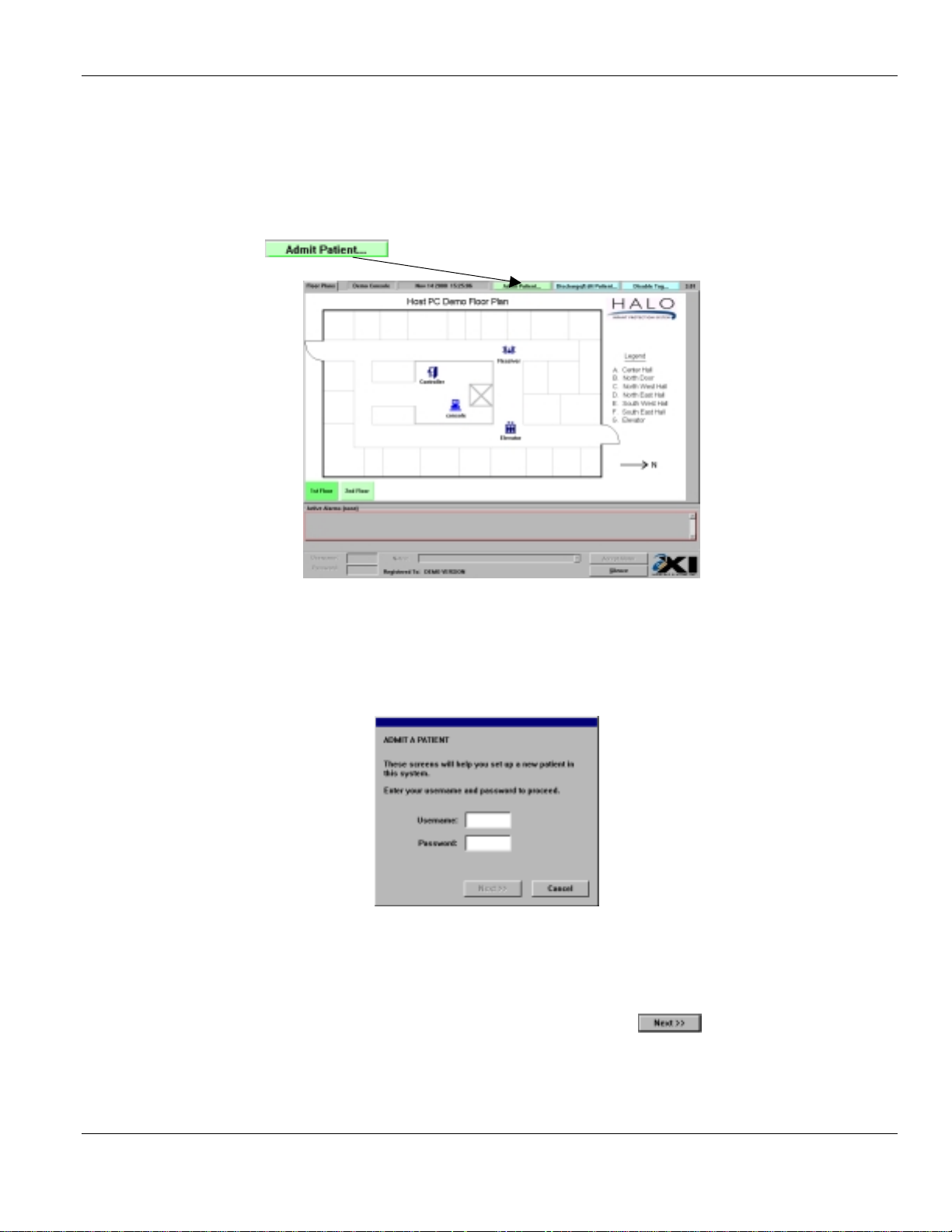
2.1. Admitt i ng a Pat ient
Select the button on the top right of the screen.
Enter Username and Password:
1. Type in your
2. Press the Θ key on the keyboard
3. Type in your
4. Press the ≅key on the keyboard, or click on the button.
5. The
Select a tag
Usernam e
Password
screen will appear.
Main Screen - User Level
as assigned by your supervisor.
EXI Wireless Systems Inc. 8 December 2000
Revision 6.0
Page 9
EXI HALO User Manual 980-000002-000
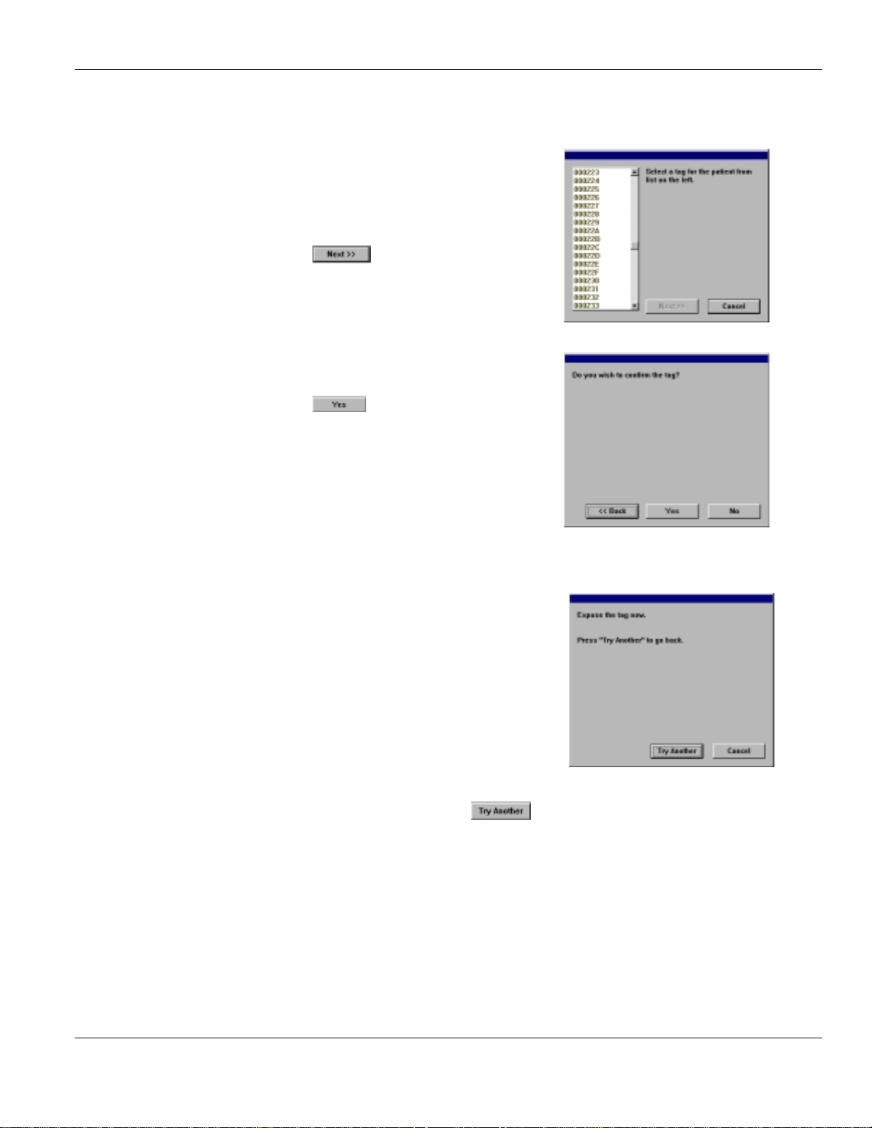
Select a Tag:
1. Select the tag number that corresponds to the serial
number on the side of the tag you wish to use. The
list contains only available tags which have been
registered in the system but not assigned to an
infant.
2. Click on to go to the
.
Confirm Tag:
Click on to begin a test of the tag.
1.
• We recommend that you test each tag before use.
The system will guide you through the process
Test tag
1. Expose the tag, or trigger an off-body TIC alarm
• During this test, the system is
• verifying the tag serial number
Confirm Tag
step
• testing the tag removal alarm
• gene r ati ng an a ct iv it y lo g ent ry t o d oc ument the
test.
If the test is successful, the system will take you to the next step in the admit process.
If the controller cannot detect the tag, select to go back and try another tag.
Ensure the bottom of the tag is held stable on your skin during the test for about 10 seconds prior to
removing.
If the test fails, try it once more on your wrist.
EXI Wireless Systems Inc. 9 December 2000
Revision 6.0
Page 10
EXI HALO User Manual 980-000002-000
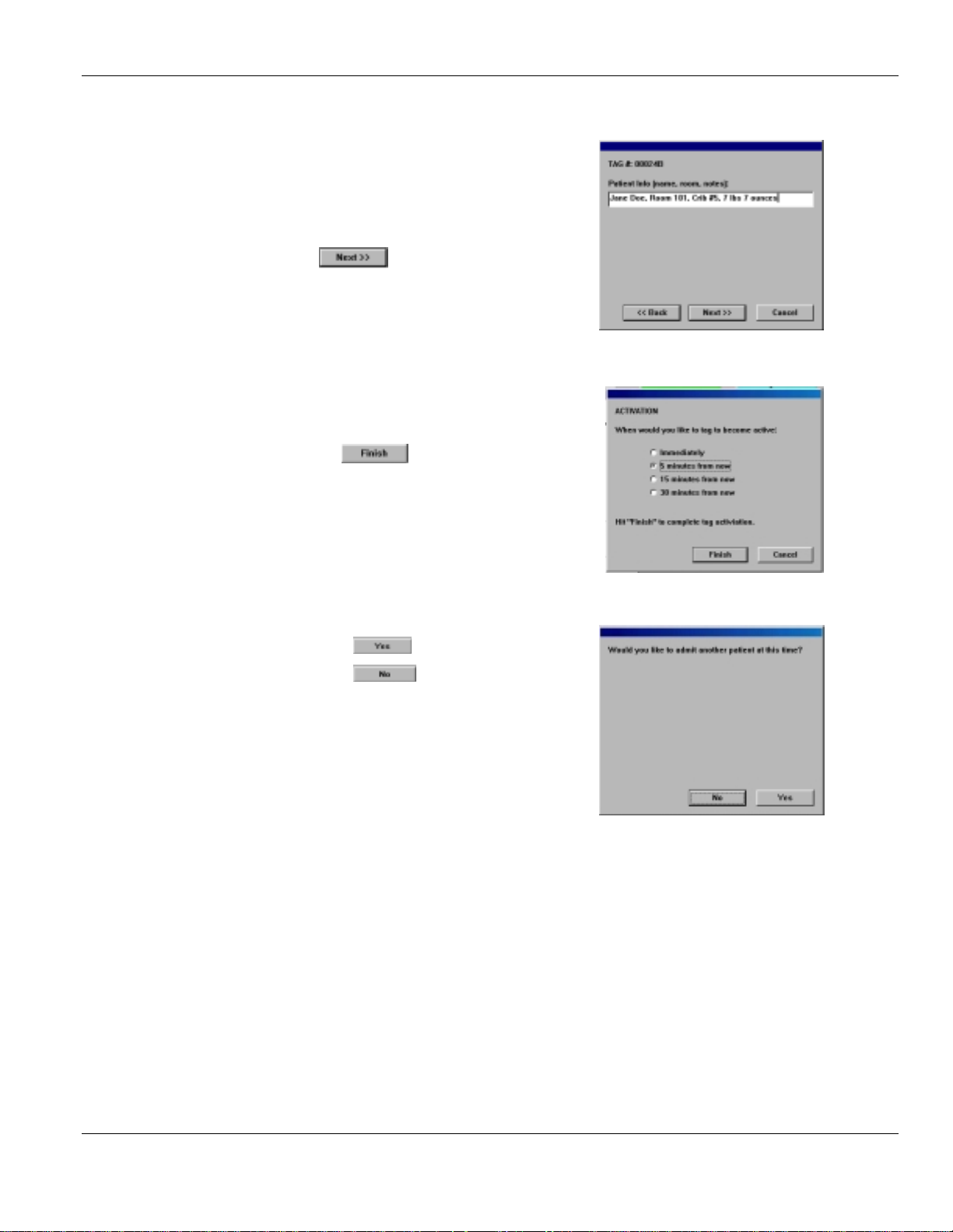
Enter Patient Information:
1. Verify that the
number on the Tag you have just selected
2. Type the
3. Click when done.
Choose Activation Delay:
1. Select the required
2. Click on to complete the admission
3. NOTE that Delays apply to sensing “off- body” or
TIC alarms only. Tag will still initiate alarms at
egress points.
Patient info
shown matches the serial
Tag #
Activation
delay
1. Click on to admit another patient
2. Click on to return to the main screen
EXI Wireless Systems Inc. 10 December 2000
Revision 6.0
Page 11
EXI HALO User Manual 980-000002-000
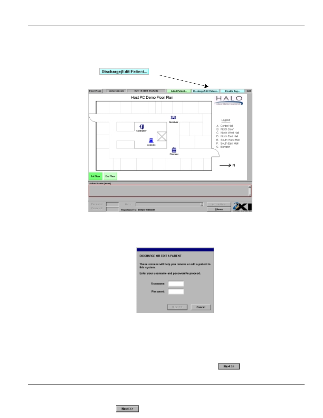
2.2. Di scharging or Editing a Patient
Select the button on the top right of the screen.
Enter Username and Password:
1. Type in your
2. Press the Θ key on the keyboard
3. Type in your
4. Press the ≅ key on the keyboard, or click on the button.
Usernam e
Password
Main Screen - User Level
as assigned by your supervisor.
Select Option
EXI Wireless Systems Inc. 11 December 2000
Revision 6.0
Page 12
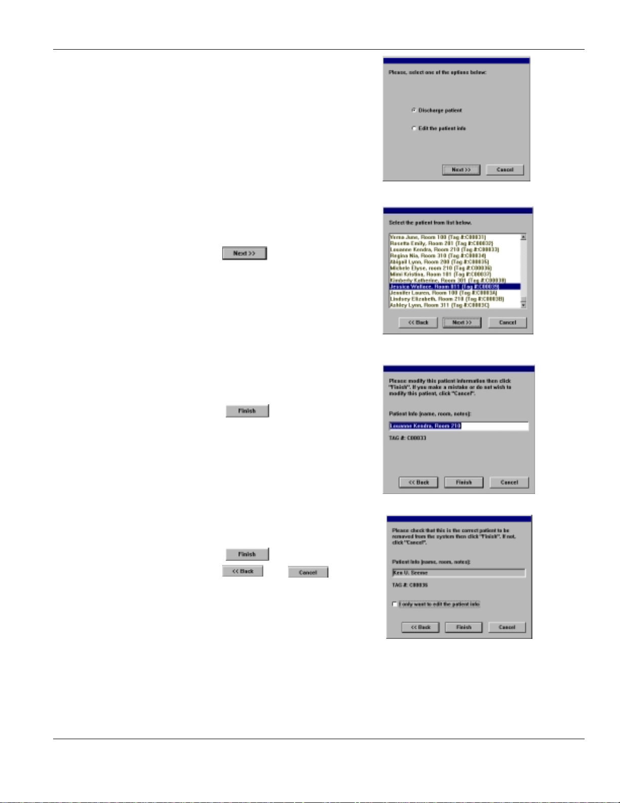
EXI HALO User Manual 980-000002-000
1. Select the option require.
2. Click on
Select Patient:
1. Select the
either discharge or edit
2. Click on .
Editing a Patient’s Info:
1. Type the changes to the existing information
2. Click on
Patient Name/Tag
that you wish to
Discharging a Patient:
1. Verify the
2. Click on to discharge the infant
3. Click on or if the infant
is not to be discharged.
4. Note: The system will continue to respond to a
tag detected at an egress point, such as a
doorway or elevator, and control that egress
point even after the tag has been discharged.
EXI Wireless Systems Inc. 12 December 2000
Infant Name
Revision 6.0
Page 13

EXI HALO User Manual 980-000002-000
2.3. Disabli ng a Tag Temporar i l y
The newest version of the HALO™ software allows a user with
temporarily disable a tag for a period of 5, 10 or 15 minutes.
To temporarily disable a P-Tag from the console:
Select the button on the top-right hand corner of the console.
Main Screen - User Level
Te am Leade r
or
Supervisor
access to
Enter username and password:
1. Type in your
2. Press the Θ key on the keyboard
3. Type in your
4. Press the ≅ key on the keyboard, or click on the button.
Usernam e
Password
as assigned by your supervisor.
EXI Wireless Systems Inc. 13 December 2000
Revision 6.0
Page 14

EXI HALO User Manual 980-000002-000
Select patient:
1. Select the patient whose tag you wish to disable
2. Click on press the button.
Choose time delay:
1. Select the length of time the tag is to be disabled for
2. Click on
• Choose the minimum time that you think is necessary
• The Disable Tag feature accessible from the Control
Panel only
• Only off-body (TIC) alarms are delayed for the
selected amount of time.
• TIF alarms, created when a tag is near an egress point can still be triggered during this pe-
riod.
Click on to disable another tag
Click on to return to the main screen
EXI Wireless Systems Inc. 14 December 2000
Revision 6.0
Page 15

EXI HALO User Manual 980-000002-000
2.4. Silencing and A ccepting Alarms
The HALO™ system will cause an alarm when:
• An assigned infant tag has been removed from an infant (off-body or TIC).
• When an infant tag is detected near a controlled egress area (in-field or TIF).
When an alarm occurs, the Alarm Acceptance Area will appear and the system will:
• Identify the infant associated with the detected tag.
• Identify the location by flashing an icon and expressing the location name.
• Identify the alarm type as a tag removal or egress area detection.
• Sound an audible alarm at the computer.
When multiple system devices see the same tag in alarm, the system will condense them into one incident. However, each alarm must be Accepted individually.
Alarm
Acceptance
Area
Main Screen - User Level
EXI Wireless Systems Inc. 15 December 2000
Revision 6.0
Page 16

EXI HALO User Manual 980-000002-000
Silencing an alarm
1. Click on
• After the alarm has been investigated you must Accept it.
Accepting an alarm
• Select the alarm condition in the
automatically be selected.
1. Type in your
2. Press the Θ key.
3. Type in your
4. Press the ≅ key.
5. Enter a note in the
• by typing from the keyboard
or
• selecting a pre-defined note from the drop down list. Use the up and down arrows to
find the note you want, and then select that note
Click on
6.
Usernam e
Password
Notes
field You may not proceed until a Note has been entered
Active Alarms
field. If only one alarm exists, it will
The system will log the following incident details:
EXI Wireless Systems Inc. 16 December 2000
Revision 6.0
Page 17
EXI HALO User Manual 980-000002-000
• Alarm type (tag removal or egress alarm)
• Infant name
• Tag number
• Time
• ID of staff member accepting the alarm
• Staff member notes on alarm incident
2.5. “Nurse Saver” and “Loitering” Feat ur es
• If the system is installed with the “Nurse Saver” feature, Tags detected at egress points that
are secured will not set off nuisance alarms.
• A Tag detected near a door that is closed will result in the appropriate floor button on the
computer screen turning yellow (pre-alarm), and the icon associated with that door also
turning yellow.
• If a bypass keypad is installed at the door, it will flash a light and emit periodic “beeps” to
indicate the presence of the Tag. This event is logged into the computer as “Tag detected
at location xxx”, but will not create an alarm condition.
• If the door is opened while the Tag is still near the door an alarm will be initiated. This
feature can only operate if the door is equipped with a magnetic switch to sense whether it
is open or closed.
• If the tag remains near the door for a period of one minute or more, an egress alarm will be
initiated and the button and the icon on the screen will both turn to red. This is the “Loitering” feature.
Alarm (Red)
Pre-Alarm
(Yellow )
EXI Wireless Systems Inc. 17 December 2000
Revision 6.0
Page 18

EXI HALO User Manual 980-000002-000
2.6. Improperl y Stor ed Tags
• When a tag generates 20 or more off-body (TIC) alarms in a 24-hour period this usually means that the
tag is improperly stored.
• When this occurs, a warning message will be displayed on the screen.
1. Note the Tag number
2. Follow the Instructions in the Warning Message
3. When you have read the message, click the button.
• It is recommended that you attempt to locate the tag after the above message is given.
• Improperly storing a tag will void the tag warranty
EXI Wireless Systems Inc. 18 December 2000
Revision 6.0
Page 19

EXI HALO User Manual 980-000002-000
3. SUPERVISOR LEVEL FUNCTIONS
3.1. Accessing Supervisor Level
1. Hold the Ξ down, and press the Θ key.
2. Enter your
3. Press the Θ key on the keyboard
4. Enter your
5. Click on the Supervisor screen will appear - as shown below.
Supervisor Tabs
Usernam e
Password
Supervisor’s Screen
EXI Wireless Systems Inc. 19 December 2000
Revision 6.0
Page 20

EXI HALO User Manual 980-000002-000
Supervisor mode has four different functions, each of which can be accessed from one of the four supervisor tabs shown in the figure above. There are:
• Activity
• Tags
• Users
• Annotations
Supervisor Level Functions
Supervisor tab Access Functions
Activity Supervisor only View activity logs
Annotate activity logs
Print logs
Tags Supervisor only Add or delete tags
View registered tag list
Disable a tag
Unassign a tag
Edit patient information for tag
View current infant population
Change expiry date of tags
Locate a tag
Print list of tags
Users Supervisor only Add or delete a user
Disable or Activate a user
Change user passwords
Annotations Supervisor only Add or delete alarm annotations
Edit an annotation
3.2. Exiti ng Super visor Level
Click on the button at the bottom of the screen.
EXI Wireless Systems Inc. 20 December 2000
Revision 6.0
Page 21

EXI HALO User Manual 980-000002-000
4. ACTIVIT Y LOG MANAGE MENT
4.1. Activity Logs
The system gives supervisors the ability to search the historical activity log. The system will record:
• Patient admission and discharge
• Alarm events including acceptance parameters
• System diagnostics
• Entry and Deletion of new tags and users
• Warning of unassigned tags or tags not in the database
• Door bypass activity
From the Supervisor Screen
Click on the Supervisor function tab
Activity Screen - Supervisor Level
The activity log screen will display:
• The time and day of activity
• The type of activity
• Description of the activity
• The user name associated with the activity
• The user notes.
EXI Wireless Systems Inc. 21 December 2000
Revision 6.0
Page 22

EXI HALO User Manual 980-000002-000
4.2. Navigating the activity l og
To look at an activity event on a specific day find the day using the “Day” buttons.
To step one day back, click on
To step one day forward, click on
The date you are viewing will appear in the leftmost column.
4.3. Addi ng a Supervisor annotation to an alar m
1. Select the particular alarm you wish to annotate.
2. .Click on the Supervisor tab labeled
3. Enter the note
4. Select to accept, or to
cancel
EXI Wireless Systems Inc. 22 December 2000
Revision 6.0
Page 23

EXI HALO User Manual 980-000002-000
4.4. Backing up Activity Logs
For security and audit purpose we recommend that you copy the Activity Logs on a r egular basis. The
system is ca pable of storing 14,000 events in the Activity Logs. After the 14,000 events are captured,
subsequent events displace the fi rst log in the list. That is, events ar e purged on a first-in first-out basis
after the 14,000 limit is reached.
Reme mber that all system activi ties, including a larm conditions , pre-a larm conditions, door acces s and
bypass activities are logged.
To make a copy, or back-up, file of an Activity Log on the computer Hard Drive
1. you must be in Supervisor mode — see section 3.
2. Simultaneously press the Ξ and β keys on the Keyboard.
3. A window will appear, asking you to specify the filename and directory for the backup file
storage. This window contains the default directory “Backup” and the default file name of
the year, month, date, hour, minutes, and seconds when the backup was initiated. You can
type in your own file name, or use the default. Click on the button to save the
backup file to the hard drive, or press to cancel the backup operation.
4. To access the back-up file look in the HALO™ directory using Windows Explorer
To make copies of these files for archiving, you w ill need to exit the HALO™ Console application and
manually copy the back-up file to the removable back-up media (such as a ZIP Disk) using the Windows
Explorer program.
EXI Wireless Systems Inc. 23 December 2000
Revision 6.0
Page 24

EXI HALO User Manual 980-000002-000
5. MANAGING TAGS
5.1. Tags
Your system requires each infant to wear a P-Tag. You should have a fleet of tags on hand that exceeds
your peak demand. Each tag has a unique serial number that is on the side of the tag.
The tag management tab allows a Supervisor to:
• Add new tags to the system.
• Delete tags from the system.
• View the existing tag fleet and edit the properties of each.
• Disable or Unassign a tag.
• Edit patient information for an assigned tag.
• Print the list of tags in the fleet.
• Change a tag’s expiry date.
• Locate a tag.
• Print the tag listing.
To manage tags, you must be in the Supervisor mode – see Section 3.
• Click on the Supervisor tab labeled
Tags Management Screen - Supervisor Level
EXI Wireless Systems Inc. 24 December 2000
Revision 6.0
Page 25

EXI HALO User Manual 980-000002-000
5.2. Adding a new P-Tag to the system
To add a new P-Tag to the system, you must be at the
P-Tags may be added to the system manually from the console, or by using the HALO™ network to read
them.
When a number of Tags are to be added we suggest that you use the HALO™ network
To add manually:
1. Click on on
2. Click on
3. Enter the serial number in the
4. If you wish to enter a Range of tags, click the
button, if not skip to step 6.
5. Enter the
6. Enter the ta g
the month and year or selecting from the
menus using the drop-down arrows.
7. Select
To use the HALO™ network to read the tags in:
Starting ID
Tag Management Screen
Tag ID (Start)
and the
Expiry Date
End ID
ei ther by keying
Tags Management Screen
field.
.
1. Select
2. Select the device you wish to use to
read the tags
3. Click on
• The device will be
• Note – a device in Reader Mode is
not available for normal alarms
4. Enter the tag expiry date either by
keying the month a nd yea r o r se l e c t i ng f r o m the
menus using the drop-down arrows.
5. Wave the tag in the air ensuring you are not
contacting the bottom of the tag. The HALO™
software will read the tag in to the system
automatically.
6. Exit Reader Mode by clicking on the button.
• It is important to
to report alarms.
Reader Mode
Clear Reader Mode
to ensure that the device comes back on line and is ready
EXI Wireless Systems Inc. 25 December 2000
Revision 6.0
Page 26

EXI HALO User Manual 980-000002-000
5.3. Dele t i ng a P- Tag f r om the system
To delete a P-Tag, you must be at the
Tags Management Screen
To delete a tag:
Select the tag to be deleted
1.
Click on button.
2.
Tags Management Screen - Supervisor Level
EXI Wireless Systems Inc. 26 December 2000
Revision 6.0
Page 27

EXI HALO User Manual 980-000002-000
5.4. Disabli ng a P- Tag
• Disabling a tag can now be done from the console screen or from the supervisor level.
• Tag disabling allows for removal of the tag from the infant without triggering an alarm. The infant is
not discharged from the system.
• Once you have disabled the tag you are responsible to enable it again or remove the infant from the
system.
• This event is captured in the Activity log.
To disable a P-Tag
1. Select the tag to be disabled
2. Click on
5.5. Unassi gni ng a P- Tag
• P-Tags can only be unassigned from the
• The patient’s name will be removed from the system when the tag is unassigned.
To unassign a tag:
1. Select the tag to unassign
2. Click on
Tags Management Screen
EXI Wireless Systems Inc. 27 December 2000
Revision 6.0
Page 28

EXI HALO User Manual 980-000002-000
5.6. Editi ng a P- Tag Record
• P-Tags can only be edited from the
• Only P-Tags assigned to a patient may be edited.
• The edit function allows a Supervisor to edit the
To edit a P-Tag record
1. Select the tag to be edited
2. Click on
3. Enter the r eq ui re d de ta i l s i n the
field
4. Click on to accept changes,
or to undo changes.
5.7. Changing a Tag’s Expiry D ate
• P-Tags Expiry dates can only be changed from the
• This feature should be used with extreme caution
Tags Management Screen
Tag info
Tag inf o
Tags Management Screen
in Supervisor level.
associated with the tag serial number
• The tag’s expiry date is an important safety feature, which is meant to prevent tags which have
old batteries from being used in the field.
To change a tag’s expiry date
1. Select the tag on the
2. Click on.
3. Enter the tag
month and year or selecting from the menus using the drop-down arrows.
4. Click on to accept change,
to abandon change.
Tags Management Screen
Expiry Date
either by keying the
EXI Wireless Systems Inc. 28 December 2000
Revision 6.0
Page 29

EXI HALO User Manual 980-000002-000
5.8. Locate a Tag
! This feature allows you to see the last ten detections of a certain tag.
! If an infant has been abducted, this is an easy way to determine the route that the sus-
pected kidnapper may have taken.
To locate a tag:
1. Select the tag by highlighting the appropriate line on the
2. Click on
• A screen will appear showing the last ten detections for the selected tag.
3. Click on when you are finished viewing.
Tags Management Screen
.
EXI Wireless Systems Inc. 29 December 2000
Revision 6.0
Page 30

EXI HALO User Manual 980-000002-000
6. MANAGING SYSTEM USERS
• Only supervisors can give a user access to the system, and assign their level of access.
A supervisor can assign, delete, and edit another supervisor’s access level.
• Every system user requires a username and password, and these can only be assigned
and entered into the system by a supervisor.
• The installer/administrator will assign access to the first supervisor. The default ad-
ministrator user name is “dealer” and password is “dealer”.
• After assigning access it is important that the first administrator change the default
password
To access the
User Management Screen
• Click on the tab on the Supervisor’s Screen
User Management Screen - Supervisor Level
The user management screen displays:
• The current authorized users
• The usernames
• Status (Active or Disabled)
• The identity of the Supervisor assigning the user
• The last date of user file edit or entry
• The access level of the user
EXI Wireless Systems Inc. 30 December 2000
Revision 6.0
Page 31

EXI HALO User Manual 980-000002-000
6.1. Adding a new user to the system
• New users can only be added from the
Click on
1.
2. Enter the
3. Enter the
4. Enter the
5. Select an
6. Choose the user’s Access Level
•
•
•
Usernam e
Password
Real Name
Access Level
level gives access to the console to accept
User
alarms, silence alarms, admit and discharge
patients.
Team Leader
functions plus the
Supervisor
described in Section 3.1.
followed by the Θ key
followed by the Θ key
.
level gives access to the
Disable Tag
level gives access to all functions as
feature.
User Management Screen
User
7. Click on
EXI Wireless Systems Inc. 31 December 2000
Revision 6.0
Page 32

EXI HALO User Manual 980-000002-000
6.2. Dele t i ng a user fr om the system
• Users can only be deleted from the
1. Select the user you wish to delete
2. Check that you have selected the required user — this step cannot be undone.
Click on
3.
6.3. Disabli ng / Enabling a system user
• This function allows a supervisor to temporarily disable the access of a particular user;
and re-enable them later.
• This may be useful when a nurse is away for a short period but is expected to return.
• Instead of deleting and re-entering all of the nurses’ information, the user’s data remains in
the system when the user is Disabled and is quickly restored with the Enable function.
• Users can only be Disabled / Enabled from the
1. Select the user you wish to Disable / Enable
User Management Screen
User Management Screen
.
2. Click on the
read
Disabled or Enabled
6.4 . Editing a syst em u ser ’s a ccess l eve l
• A supervisor may change a user’s password, “real name”, and access.
• The system user name may not be changed — the user name must be Deleted and the new
one Added.
• User details can only be Edited from the
1. Select the user you wish to edit
2. Click on
3. Enter the changes
Disable
button or the
as appropriate
button as required. The user’s status field will
Enabl e
User Management Screen
.
EXI Wireless Systems Inc. 32 December 2000
Revision 6.0
Page 33

EXI HALO User Manual 980-000002-000
7. PRINTING LOGS
You can print the following logs:-
• activity log
• tag listing
• user listing.
To initiate printing, click on the button. A preview of the printout will appear as
shown below.
Click on to proceed with printing, or on to cancel.
EXI Wireless Systems Inc. 33 December 2000
Revision 6.0
Page 34

EXI HALO User Manual 980-000002-000
8. MANAGING ALARM ANNOTATIONS
• When a user Accepts an alarm (see Section 2.4) they have the option either to enter a Note
or to select a Note from a menu which a supervisor has created. The Notes are entered in
the Alarm Acceptance Area of the screen.
• Supervisors may add a new note, or change an existing note in the
• Click the
• You will see the list of Notes already available to users when Accepting an Alarm
tab on the Supervisor Screen
Notes
list
Annotation Management Screen – Supervisor Level
EXI Wireless Systems Inc. 34 December 2000
Revision 6.0
Page 35

EXI HALO User Manual 980-000002-000
8.1. Addi ng an A nnot ation
1. Click on
2. Type in your annotation in the window that appears
3. Click to accept changes or to cancel .
8.2. Del et i ng an Annotati on
1. Select the Annotation you want to delete
2. Click on
• The annotation will be deleted.
8.3. Editi ng an Annotati on
1. Select the Annotation you want to
change
2. Click on
3. Edit the Annotation and select
to accept or to
undo changes.
EXI Wireless Systems Inc. 35 December 2000
Revision 6.0
Page 36

EXI HALO User Manual 980-000002-000
9. SHUT TING DOW N AND RE S TARTING THE SYST E M
9.1. Shutting down
• The system can only be shut down from the Supervisor Level.
• We recommended that the system is shut down only for servicing because once it is shut
down events will not be logged.
• Door units will remain active and the exit doors will be locked if your system is designed
to do so.
• To shut down the system:
1. Press the Ξ and θ keys on the keyboard simultaneously.
Re sta rting th e sy ste m —
9.2.
if this is required more than once a week, contact your dealer
To restart the system either
1. Turn off the computer, then turn it on again. (HALO™ will automatically launch).
2. From the Windows 98 desktop, either
1. double-click on the “Halo Console” icon
or
2. select Start Menu, Programs, Halo, and click on
EXI Wireless Systems Inc. 36 December 2000
Revision 6.0
Page 37

EXI HALO User Manual 980-000002-000
APPENDI X A - LIMIT E D WARRANTY
1.
Warranty:
uct, other than t r ansponders (th e “Transponders”), accompanying this warranty (the “Product”), will be free of defects in materials and
workmanship for a period (the “Product Warran t y Period” ) of two years after the date of the original sale by EXI of th e Pr oduct; and (b)
each Transponder accompany ing t his warra nty will be free of defects and workmanship for a period (the “Transponder Warranty Period”) of, i n the case of a WTX-INF/WS Transponder, fou r years, and in the case of all other Transponders, three years, after the date of
the original sale by EXI of the Transponder.
2.
Notification:
may be, discovers a def ect in materials or workmanship of a Pr oduct wit hin t he Product Warr anty Period, or a Transponder withi n the
applicable T r ansponder Warranty Peri od, the Purchas er must, w ithin 30 days after the date of such discovery, notif y EXI of such defect,
and at EXI’s request, return th e defectiv e Pr oduct or Transponder, as case the may be, to EXI.
3.
Repair or Replacem ent:
in the case of a Product, either replace the Product, or provide the Purchaser with replacement parts for, or repair, the same; and (b) in
the case of a Transponder, replace th e Transponder at a discoun ted pr ice equal t o t he product of : (i) the nearest whole number of months
remaining in the applicable Transponder Warranty Peri od; and (ii) th e amount of t he then monthly credi t available from EX I f or the applicable Transponder. EXI’s warranty in respect of any replacement Product, part t hereof, or Transponder, as the case may be, will be fo r
the unexpired portion of the or igi nal warr anty period applicable to the relev ant Product or Transponder.
4.
Exclusion:
makes no other warranty or representation, express or implied, and hereby disclaims any implied warranty of merchantability or fitne s s fo r
a particular purpose, statutory or otherwise, concerning its Products and Transponders. In addition, the warranty will not apply if EXI has
not received a fully completed warranty registration card in respect of the P roduct or Transponder, as the case may be, within 30 days
aft er t he date of the ori ginal purch as e from EXI of the same, or the Product or Transponder, as th e case may be, or any part ther eof: (a) is
damaged by misuse, accident, negligence, lightning, power surge, brown-out, or leaking, damaged or inoperative batteries, or failure t o
mai ntain t he Product or T ransponder as specified or r equired by EXI; (b) i s damaged by modifications, alterations or attachments thereto
wh ich are not authorized by EXI; (c) is installed, operated or repai red contrary to the instructions of EXI; (d) is opened, modified or disassembled in any way wit hout EXI’s consent; or ( d) is used in combination with items, articles or materials not authorized by EXI.
5.
Limitation:
the total amount of the purchase price actually paid by the Purchaser to EXI for the Product or Transponder, as the case may be. Specifica lly, EXI will not be liab le fo r : (a ) any s pe c ial, indir e ct o r c o n s eq uent ia l da ma ge, includ ing lo st p ro fit s , lo st r eve nu e s , fa ilu r e to r e alize
ex p ec t ed sa v ings, or o the r co mmer cia l or e co nomic losse s of a ny k in d , e ven if EX I has be e n ad vise d of t he p o ss ib ility o f suc h dam ag e;
(b) any loss or damage to an y property or for any personal i njury or economic loss or damage caused by the con nection of the Product or
Transponder, as applicable, to oth er devices or systems; (c) any damage or inju ry arising from or as a result of , misuse, abu s e or incorrect
installation, integr at ion or operation of the Product or T r ansponder, as appl icable, by person s not aut horiz ed by EXI; or (d) any de fe c t in
any batteries added to or used in conjunct ion with th e Pr oduct or Tran s ponder.
Subject t o the li miting conditi ons set forth below, EXI Wireless Systems Inc. (“EXI” ) hereby warrants that: ( a) each prod-
If t he orig inal or any subsequent purchaser (collecti vely, the “Purchaser”) of the Product or Tr ansponder, as the case
Subject t o §4, upon acceptance by EX I of responsibilit y for the de fe ct, EX I w ill, in it s so le dis c re t ion, (a )
The warranty referred to in §1 is the sole warranty made by EXI with respect to its Products and Transponders. EXI
E XI will o nly be lia ble t o th e Pur c h a se r for d irect d amages s u ffe re d by t he P ur cha se r up t o a maximum a mo unt eq ual to
6.
Product Limitation:
teed to prevent wandering patients, infant abductions, theft or any other event for which they were purchased, (ii) the Products and
Transponders are only intended to provide additional safeguards to assist in the prevention of events such as those described in §(i), a nd
(b) understands fully the foregoing limitations concerning the Products and Transponders, including EXI’s limitation on liability described i n
§5, and agrees to warn, and obtain acknowledgem ents from, all users thereof of the same.
7.
No Additional Warranties:
ucts and Transponders and supersede all previous negotiations, understandings, communications, representations, warranties and
agreements, w hether ver bal or wri t ten, concerning the Products and Transponders.
8.
Deem ed Accep t ance:
an acceptance by the Purchaser of t he terms hereof.
9.
Governing Law :
Pu r cha s er here b y at to r ns t o the exc lusive j u r is dic t ion o f the laws of Br itish Co lumb ia. Th e pr o v is ions of th e U nite d Na t ions Convention
on Contracts for the Internat ional Sale of Goods is hereby excluded.
EXI Wireless Systems Inc. 37 December 2000
The Purchaser (a) acknowledges that (i) the Products and the Transponders are not, nor can they be, guaran-
The terms and conditions herein contain all the warranties and representations concerning EXI’s Prod-
The installation or use of the Product or Transponder by or at the direction of the Purchaser will be deemed as
The w a rrant y h e re in w ill b e go ver ned b y t he d omes tic la w s of t he P r ovince o f Brit is h C olumbia, C a n a da and th e
Revision 6.0
Page 38

EXI HALO User Manual 980-000002-000
APPENDI X B - FCC REGULATIONS
This device complies with Part 15 of the FCC Rules. Operation is subject to the following two conditions:
(1) This device may not cause harmful interference, and (2) This device must accept any interference received, including interference that may cause undesired operation.
This equipment has been tested and found to comply with the limits for Class B Digital Device, pursuant to
Part 15 of the FCC Rules. These limits are designed to provide reasonable protection against harmful interference in a residential installation. This equipment generates and can radiate radio frequency energy and, if
not installed and used in accordance with the instructions, may cause harmful interference to radio communications. However, there is no guarantee that interference will not occur in a particular installation. If this
equipment does cause harmful interference to radio or television reception, which can be determined by
turning the equipment off and on, the user is encouraged to try to correct the interference by one or more of the
following measures:
• Reorient or relocate the receiving antenna
• Increase the separation between the equipment and receiver
• Connect the equipment into an outlet on a circuit different from that to which the receiver is
connected
• Consult the dealer or an experienced radio/TV technician for help
Any changes or modifications not expressly approved by the party responsible for compliance could void the
user’s authority to operate the equipment.
EXI Wireless Systems Model No.: Patient Tag
CANADA: 287710217261A FCC ID: HE7 PTG
This device complies with Part 15 of the FCC Rules. Operation is
*
subject to the following two rules: ( 1) This device may not cause harmful
interference, and (2) This device must accept any interference recei ved,
including interference that may cause undesired operation.
Made in Canada
EXI Wireless Systems Model No.: Halo Infant/ECO tag
CANADA: 28771031940 FCC ID: HE7 ETG
This device complies with Part 15 of the FCC Rules. Operation is
*
subject to the following two rules: ( 1) This device may not cause harmful
interference, and (2) This device must accept any interference recei ved,
including interference that may cause undesired operation.
Made in Canada
EXI Wireless Systems Model No.: Halo Asset tag
CANADA: 28771032080 FCC ID: HE7 ATG
This device complies with Part 15 of the FCC Rules. Operation is
*
subject to the following two rules: ( 1) This device may not cause harmful
interference, and (2) This device must accept any interference recei ved,
including interference that may cause undesired operation.
Made in Canada
EXI Wireless Systems Inc. 38 December 2000
Revision 6.0
Page 39

EXI HALO User Manual 980-000002-000
APPENDI X C - S YST E M MAINT E NANCE
HALO™ is designed to assist staff in providing a higher degree of safety for patients. It is not intended as
the sole means of protection in preventing a wanderer or infant from leaving the premises. Regular checks to
verify that your HALO™ system is operational are highly recommended.
SYSTEM MAINTENANCE SHOULD INCLUDE THE FOLLOWING STEPS:
• All Tags should be checked for physical damage after each cleaning, disinfecting or steriliza-
tion procedure.
• Each Tag should be tested for correct operation before being attached to an infant. The
HALO™ software pr ompts for testing of Tags prior to thei r depl oyment. Please refer to the
appropriate section in this manual for the instructions.
• The warranty on Tags is 2 years, and the batteries within the Tags are expected to last in ex-
cess of the warranty period, depending on the usage pattern. Do not leave Tags in the
detection fi eld for long periods of time, a nd store them in the foil bags supplied. Fai lure to
do so will result in false alarms, and will reduce battery life.
• Set up a regular system check schedul e to verify that the Controllers, Receivers and Tags are
operational. Controllers should have the “Ready” light illuminated to show that they are
powered. Check the operation of the Controller dai ly by starting a bypa ss or triggering an
alarm using a Tag to ensure that it is fully operational and protecting the egress point where it
is located.
• Check each Recei ver on a regular basi s to ensure that i t can receive signals from Tags in the
“Off Body” condition. Failure to regularly check for this operation may lead to failure to detect a Tag that is removed from an infant, and therefore compromising protection for the
infant.
• Whenever you see a known wandering patient, look for the Tag on their person to verify they
are still wearing it. This may require special knowledge as to the placement of the Tag.
• Conduct frequent back-ups of Activity Logs for future reference.
EXI Wireless Systems Inc. 39 December 2000
Revision 6.0
 Loading...