

Page 1
eLink PCMCIA Card: User Guide
FUNCTION
1
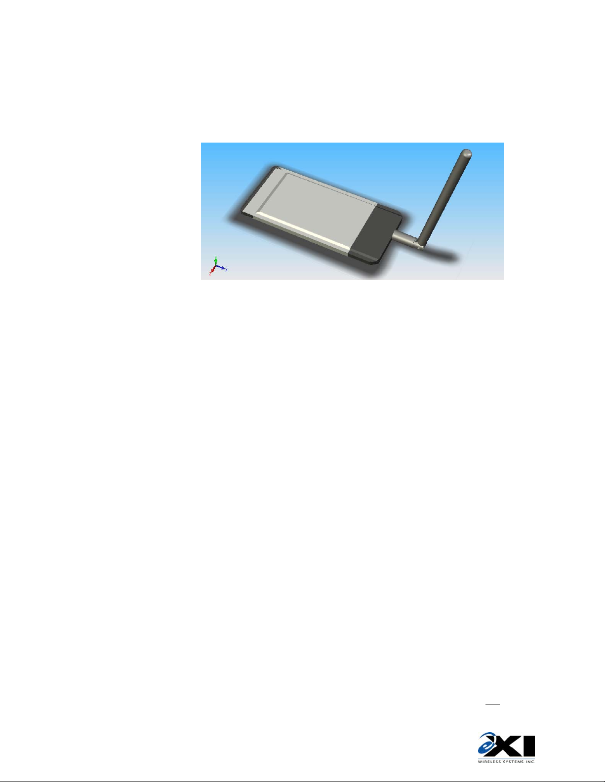
The purpose of this product is to provide a truly mobile e-Link tag reader device that detects and
displays information giving relative proximity of the Tags it is receiving messages from.
It is designed to plug into the PCMCIA card slot of a Windows CE based off the shelf device running
“eLink Mobile ReaderWare” (eMR) executable software.
INSTALLATION & POWER UP
2
Insert the eLink PCMCIA Card (ePC) in the device (e.g. Hewlet Packard I-PAQ 5500 pocket PC) and
power up the unit. Launch eMR (eLink Mobile ReaderWare) from the keypboard or touchscreen. The
ePC will not power up until initiated through eMR.
The antenna position is not critical but will generally give best reception if extended away from the
host device. There are no user adjustments required for the receiver.
OPERATION
3
Refer to eAC HUB network installation instructions for network cabling requirements.
‘Start’ Screen
• At the start screen, select either SHOW ALL TAGS or SEARCH FOR TAGS.
• eMR tries to establish communication to the “eLink PCMCIA Card”. If the card is detected the
software enters Active Mode and proceeds to the selected screen.
• If the card is not detected, the software returns to Passive Mode and shows an error message.
• While in Active Mode, if no user input is detected for more then 5 minutes and
option is selected in “PCMCIA Settings” screen, the Active Mode reverts to Passive Mode
automatically
“Power Saver”
980-000039-000R1.00
Page 2

EAC Transceiver: Installation Guide
‘Show All Tags’ Screen
• All acquired Tags are shown (Tag ID numbers) on the screen with corresponding bar graph,
• This screen is used to search for a specific Tag that was either selected from list of Tags in
• Hardware RF sensitivity can be set in this screen. There are 4 available levels of receiver
which indicates strength of received RF signal (RSSI). (The screen may be scrolled.)
• The bar-graph length is proportional to received RSSI value.
• On a top of the tag list there is a slider which allows user to set Receiver RF sensitivity. “FAR”
means high sensitivity (low RSSI threshold) and “CLOSE” means low sensitivity (high RSSI
threshold). By default this sensitivity is set to maximum (“FAR” setting). This sensitivity sets
RSSI threshold, and only messages with RSSI higher
• Refer to eMR application User Guide for additional operations on received and displayed tag
information.
than threshold are shown on the screen.
‘Search For Tag’ Screen
some other screen or has been entered in this screen.
• On screen keyboard is available in this screen that enables user to enter Tag ID number. Tag
ID must start with letters A-F and must be 6 characters in total (e.g. B12345).
• On the top of the screen there is a slider which allows user to set RF sensitivity. By default
this sensitivity is set to maximum.
• When Tag is detected bar-graph is shown, indicating received signal strength. (Bar-graph is
updated with every location message received.)
‘PCMCIA Card Settings’ Screen
sensitivity..
• “Power Saver” radio button is available. When this button is selected (default setting), and no
user activity is detected for 5 minutes, Active Mode will be interrupted, PCMCIA card powered
down and eMR will enter Passive Mode.
FCC Regulations
981-000046-000R1.00
This device complies with Part 15 of the FCC Rules. Operation is subject to the following two
conditions: (1) This device may not cause harmful interference, and (2) This device must accept any
interference received, including interference that may cause undesired operation.
This equipment has been tested and found to comply with the limits for Class B Digital Device,
pursuant to Part 15 of the FCC Rules. These limits are designed to provide reasonable protection
against harmful interference in a residential installation. This equipment generates and can radiate
radio frequency energy and, if not installed and used in accordance with the instructions, may cause
harmful interference to radio communications. However, there is no guarantee that interference will
not occur in a particular installation. If this equipment does cause harmful interference to radio or
television reception, which can be determined by turning the equipment off and on, the user is
encouraged to try to correct the interference by one or more of the following measures.
• Reorient or relocate the receiving antenna
• Increase the separation between the equipment and Receiver
• Connect the equipment into an outlet on a circuit different from that to which the Receiver is
connected
• Consult the dealer or an experienced radio/TV technician for help
Any changes or modifications not expressly approved by the party responsible for compliance could
void the user’s authority to operate the equipment.
 Loading...