

XLT Ovens 3240-AE-B, 3255-AE-B, 3270-AE-B, 3270S-AE-B, 3855-AE-B Installation & Operation Manual
...
XD-9010B-GA
Rev 03 04/07/2011
XLT Oven & AVI Hood
Installation & Operation Manual
This appliance is for professional use by qualified personnel. This appliance must be installed
by qualified persons in accordance with the regulations in force. This appliance must be installed with
sufficient ventilation to prevent the occurrence of unacceptable concentrations of substances harmful
to health in the room in which it is installed. This appliance needs an unobstructed flow of fresh air for
CAUTION
An electronic copy of this manual & warranty policy is available at: www.xltovens.com
For use with the following XLT GAS Oven Versions:
Australian (AE) B
Standard (S) B
World (W) B
satisfactory combustion and must be installed in a suitably ventilated room in accordance with current
regulations. This appliance should be serviced by qualified personnel at least every 12 months or
sooner if heavy use is expected.
For use with the following AVI Hood Versions:
Standard (S) A
World (W) A
2000887
TEL: 888-443-2751 FAX: 316-943-2769 WEB SITE: www.xltovens.com
XLT Ovens
PO Box 9090
Wichita, Kansas 67277
2
WARNING & SAFETY INFORMATION
SAFETY DEPENDS ON YOU
Improper installation, adjustment, alteration, service or maintenance can cause property damage, injury, or death. Read the installation, operating and maintenance in-
WARNING
Post in a prominent location instructions to be followed in the event you smell gas. This infor-
mation can be obtained by consulting your local gas supplier.
WARNING
In the event a gas odor is detected, shut off the gas at the main shutoff valve immediately.
Contact your local Gas Company or supplier.
Do not restrict the flow of combustion and/or ventilation air to the unit. Provide adequate
clearance for operating, cleaning, and maintaining the unit and adequate clearance for operating the gas shutoff valve when the unit is in the installed position.
structions thoroughly before installing, using, or servicing this equipment.
FOR YOUR SAFETY
Do not store or use gasoline or other flammable
liquids or vapors in the vicinity of this or any other appliance.
Keep the area free and clear of combustible material. DO NOT SPRAY AEROSOLS IN THE
VICINITY OF THIS APPLIANCE WHILE IT IS IN OPERATION.
Ovens are certified for installation on combustible floors.
Electrical schematics are located inside the control box of the oven and at the end of this man-
ual. Disconnect input power to the unit before performing any maintenance.
This unit requires a Type I ventilation hood, which requires make-up and exhaust air to ensure
adequate air supply. The installation should conform to local codes.
This unit may be operated with either natural gas or LP fuel as designated on the nameplate
label located on the side of the unit.
This unit must be operated by the same voltage, phase, and frequency of electrical power as
designated on the nameplate label located on the side of the unit.
Minimum clearances must be maintained from combustible and non-combustible construction
materials.
Follow all local codes when installing this unit.
Follow all local codes to electrically ground the unit.
Appliance is not to be cleaned with high pressure water.
Ovens are certified for use in stacks of up to three (3) units of XLT products. Integration of
other manufacturer’s products into an oven stack is not recommended, and will void any war-
ranties. XLT Ovens assumes no liability for mixed product applications.
PLEASE RETAIN THIS MANUAL FOR FUTURE REFERENCE.
SAFETY MESSAGES
For the best results with the XLT Oven and AVI Hood, carefully read this manual and all
of the warning labels attached to the products before installing and operating them, and follow the
instructions exactly. Keep this manual handy for quick reference.
Definitions and Symbols
A safety instruction (message) includes a “Safety Alert Symbol” and a signal word or
phrase such as WARNING or CAUTION. Each signal word has the following meaning:
This symbol indicates high voltage. It calls your attention to items or operations
that could be dangerous to you and other persons operating this equipment. Read
HIGH
VOLTAGE
WARNING
the message and follow the instructions carefully.
Indicates a potentially hazardous situation that, if not avoided, can result in serious
injury or death.
3
Indicates a potentially hazardous situation, that if not avoided, can result in minor to
moderate injury or serious damage to the product. The situation described in the
CAUTION may, if not avoided, lead to serious results. Important safety measures are
CAUTION
described in CAUTION (as well as WARNING), so be sure to observe them.
Notes indicates an area or subject of special merit, emphasizing either the product’s
NOTE
capability or common errors in operation or maintenance.
Tips give a special instruction that can save time or provide other benefits while installing or
using the product. The tip calls attention to an idea that may not be obvious to first-time users of the product.
TIP
Purchaser’s Responsibility
It is the responsibility of the purchaser:
To unload, uncrate, assemble, and move the ovens to their intended location.
To ensure that the gas and electric utilities are installed on site in accordance with local build-
ing codes and with the specifications in this manual.
To see that the gas and electric utilities are connected properly by a qualified installer using the
proper hardware.
To ensure a qualified installer has performed an initial start-up procedure.
In Australia, install oven in accordance with the latest version of AS5601 Gas Installation.
4
Your new oven and hood system is the result of our dedication to help you produce the finest quality baked goods. XLT Ovens has made a substantial and growing investment in capital
equipment and facilities, including state of the art CAD/CAM designing and fabricating software
and machine tools. The company has also developed ways to build quality into its products at each
stage of the manufacturing process, both through extensive use of automation and, most importantly, through an awareness that people are the central element in quality control.
XLT Ovens wants you to be totally satisfied with every aspect of owning and using your
oven and hood. Your feedback, both positive and negative, is very important to us as it helps us
understand how to improve our products and our company. Our goal is to provide you, our customer, with equipment that we can be proud to build and you can be proud to own.
To receive technical support for the oven or hood you purchased, contact the designated
representative from whom you purchased the unit, or XLT Ovens at 888-443-2751 anytime day or
night, 365 days per year. Please be prepared to provide the Model and Serial Number.
Receiving and Inspection
NOTIFY CARRIER OF DAMAGE AT ONCE
Upon receiving of all goods shipped by a Common Carrier, check for any exterior damage
that may indicate interior damage. If conditions permit, open all crates and do a full inspection for
any damage while the delivery driver is still there. If there is damage please note on the delivery
receipt and call the carrier to make a freight damage claim within 24 hours of receipt. Failure to
make a damage claim within the first 24 hours may void the opportunity to have the claim resolved.
Installation of all gas appliances and ventilation exhaust hoods should only be performed by a qualified professional who has read and understands these instructions
WARNING
and is familiar with proper safety precautions. Read this manual thoroughly before
installing or servicing this equipment.
Save this Manual
This document is the property of the owner of this equipment. Please make sure to leave
this copy with the store owner or “on site” manager, so it can be incorporated in the owners “on
site” book of manuals for future use.
XLT Ovens reserves the right to make changes in design and specifications, and/or make
additions to or improvements to its product without imposing any obligations upon itself to install
them in products previously manufactured.
All Right and Left Hand designations in this manual are from the point of view as if standing directly in front of the ovens.
TABLE OF CONTENTS
Warning & Safety Information..................................................................................................... 2
Safety Messages ........................................................................................................................... 3
Oven Description .......................................................................................................................... 6
Oven Dimensions ......................................................................................................................... 8
Gas & Electrical Connection Dimensions .................................................................................. 10
Oven Electrical Requirements .................................................................................................... 12
Oven Gas Requirements ............................................................................................................. 13
Oven Only Rough-In Specifications .......................................................................................... 15
Oven Assembly .......................................................................................................................... 17
Oven Installation ........................................................................................................................ 23
Oven Ventilation Requirements & Guidelines ........................................................................... 27
Oven Initial Start-Up .................................................................................................................. 29
Oven Operator Controls ............................................................................................................. 33
Oven Operation .......................................................................................................................... 35
Oven Cleaning ............................................................................................................................ 36
Oven Maintenance ...................................................................................................................... 40
Oven Troubleshooting ................................................................................................................ 41
Hood Description ....................................................................................................................... 44
Hood Dimensions ....................................................................................................................... 45
Hood Electrical Requirements................................................................................................... 47
Hood Ventilation Requirements ................................................................................................. 64
Hood Rough-In Specifications ................................................................................................... 65
Hood Installation ........................................................................................................................ 66
Variable Frequency Drive Adjustments ..................................................................................... 85
Hood Operator Controls ............................................................................................................. 86
Hood Initial Start-Up .................................................................................................................. 87
Hood Valance Kit ....................................................................................................................... 89
Hood Cleaning ............................................................................................................................ 92
Hood Troubleshooting ................................................................................................................ 94
International Distributors ........................................................................................................... 94
Electrical Schematics ................................................................................................................. 95
5
Revision History Table
Revision Comments Date
01 Initial Release 1/19/2011
02 Updated Hood Installation Dimensions page 45 3/8/2011
03 Revised MJ/hr 04/07/2011
6
Oven Description
This manual covers the following XLT Series Ovens and AVI Hood models:
1832-AE-B
2440-AE-B
3240-AE-B
3255-AE-B
3270-AE-B
3270S-AE-B
3855-AE-B
3870-AE-B
1832B-S
2440B-S
3240B-S
3255B-S
3270B-S
3270SB-S
3855B-S
3870B-S
1832B-W
2440B-W
3240B-W
3255B-W
3270B-W
3270SB-W
3855B-W
3870B-W
AVI-1832A-S AVI-1832A-W
AVI-2440A-S AVI-2440A-W
AVI-3240A-S AVI-3240A-W
AVI-3255A-S AVI-3255A-W
AVI-3270A-S AVI-3270A-W
AVI-3855A-S AVI-3855A-W
AVI-3870A-S AVI-3870A-W
XLT Ovens are certified to the following Standards:
“-AE” indicates Australian Export configuration, certified to AGA AS 4563.
“-S” indicates Standard configuration, certified to ANSI Z83.11/CSA 1.8 & ANSI/NSF 4.
“-W” indicates World configuration, certified to CE GAD 90/396/EEC & BS EN 203-1.
AVI Hoods are certified to the following Standards:
“-S” indicates Standard configuration, certified to UL 710, ULC-S646, NFPA 96, and ANSI/NSF 2.
“-W” indicates World configuration, certified to UL 710, ULC-S646, NFPA 96, and ANSI/NSF 2.
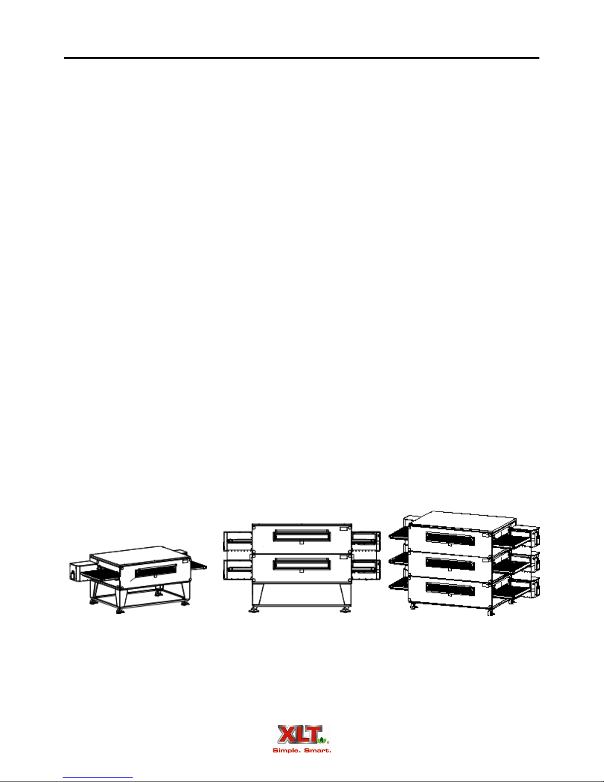
The first 2 digits of the model number represent the conveyor width and the last two digits
indicate the bake chamber length. The ovens may be used in a single, double, or triple oven stack
configuration. A single or double configuration can be upgraded by adding additional decks up to
the maximum of three. All ovens are gas-fired and are available in Natural gas or LP gas models
(Electric ovens are also available). The 3270 and 3870 models have two burners, one on each side,
and have two control boxes. All other models have only a single burner with a single control box
that can be supplied on either end. All models can be configured for a split belt conveyor.
Food product is placed on the stainless steel wire conveyor belt on one side of the oven.
The conveyor then transports the food through the bake chamber at a user-controlled speed. This
provides repeatable and uniform food cooking. The conveyors can be easily configured to move
either left-to-right or right-to-left. A large center sandwich door allows the introduction or removal of food items for cooking at shorter times. Temperatures up to 550º F or 288º C inside the
oven are achieved by means of a user-adjustable digital control.

Oven Description
An easily removable front panel allows the full cleaning of the oven interior. All exposed
oven surfaces both exterior and interior are stainless steel. The conveyor is a one piece design and
is removed from the side which has the control box. No tools are required for disassembly and
cleaning of the conveyor or oven interior. The oven itself is mounted on lockable swivel casters
for easy moving and maintenance.
Accessories such as extended conveyor shelves and perforated crumb trays are available
from XLT. In addition, moving equipment such as carts and lifting jacks are available to help install and move ovens and hoods. Please contact XLT or your designated representative for more
information.
Control Box (LH)
(3270/3870 Only)
Sandwich Door
Oven Lid
Control Box (RH)
7
Crumb Tray
Front Panel Knob
Single/Double Stack
Base Assembly
Control Box Lid
Control
Panel
(LH)
Front Panel
Product Stop
Conveyor
Swivel Caster
Data Plate
Chain Guard
Control
Box Lid
Control
Panel
(RH)
Switch Control
Models 3270 & 3870
All Models
8
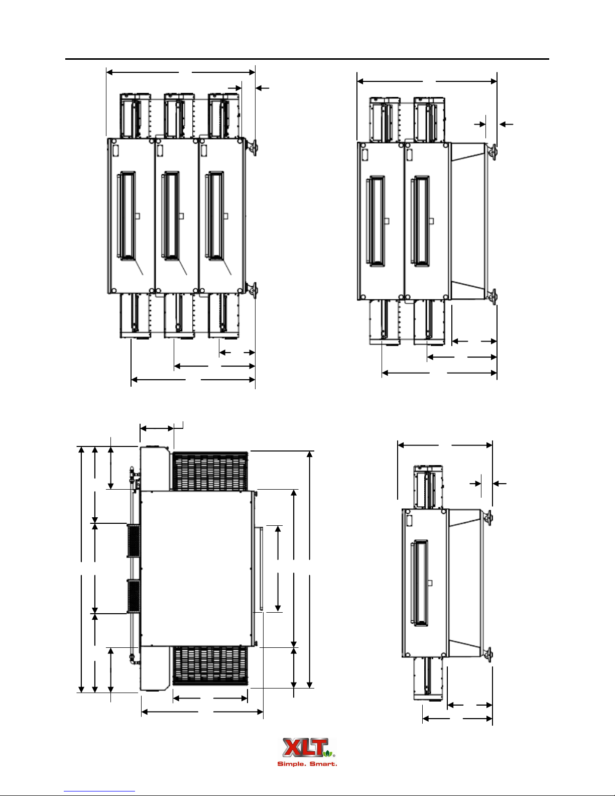
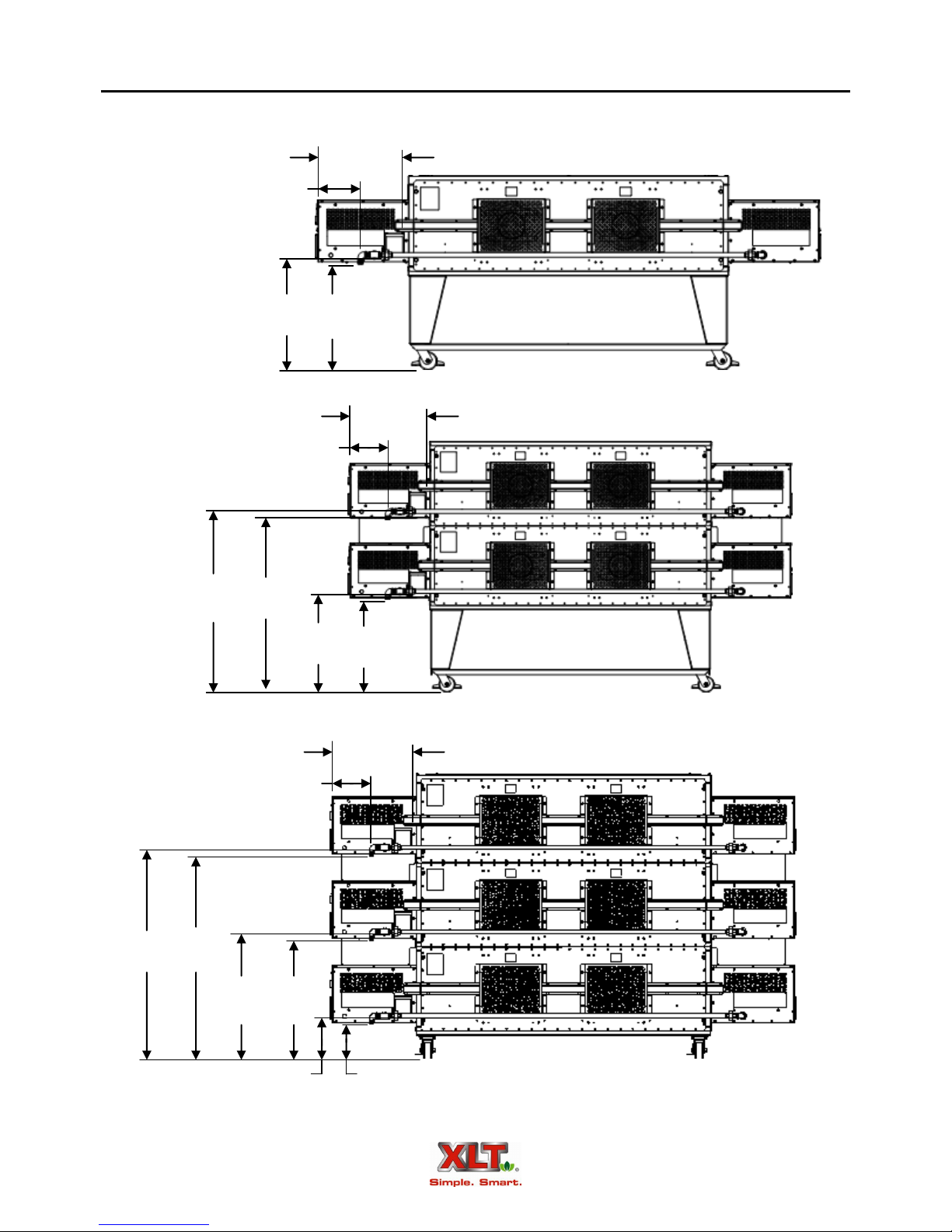
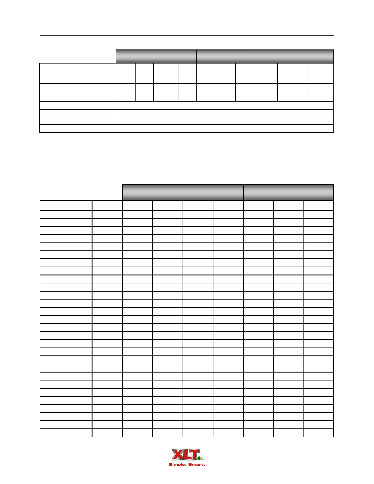
Oven Dimensions
L
K
L
K
M
N
P
Q
[530]
20.87
[502]
19.77
H
J G F
B C D
N
P
L
NOTE: All dimensions in inches [mm].
K
[502]
* 19.77
A
E
[446]
17.55
M
N
SINGLE
STACK
1832
2440
3240
3255
3270
3855
3870
DOUBLE
STACK
1832
2440
3240
3255
3270
3855
3870
Oven Dimensions
A B C D E F G H J K L M N P Q WEIGHT
19.41
32.13
67.25
19.72
47.23
[493]
[816]
[1708]
[501]
25.41
40.13
75.25
[645]
[1019]
33.41
40.13
[849]
[1019]
33.41
55.13
[849]
[1400]
33.41
70.13
[849]
[1781]
39.41
[1001]
[1001]
[1001]
[1001]
55.13
[1400]
39.41
70.13
[1781]
A B C D E F G H J K L M N P Q WEIGHT
19.41
32.13
[493]
[816]
25.41
40.13
[645]
[1019]
33.41
40.13
[849]
[1019]
33.41
55.13
[849]
[1400]
33.41
70.13
[849]
[1781]
39.41
55.13
[1400]
39.41
70.13
[1781]
[1911]
75.25
[1911]
90.25
[2292]
105.25
[2673]
90.25
[2292]
105.25
[2673]
67.25
[1708]
75.25
[1911]
75.25
[1911]
90.25
[2292]
105.25
[2673]
90.25
[2292]
105.25
[2673]
19.72
[501]
19.72
[501]
37.72
[958]
37.72
[958]
37.72
[958]
37.72
[958]
19.72
[501]
19.72
[501]
19.72
[501]
37.72
[958]
37.72
[958]
37.72
[958]
37.72
[958]
[1200]
53.23
[1352]
61.23
[1555]
61.23
[1555]
61.23
[1555]
67.23
[1708]
67.23
[1708]
47.23
[1200]
53.23
[1352]
61.23
[1555]
61.23
[1555]
61.23
[1555]
67.23
[1708]
67.23
[1708]
N/A* N/A*
N/A* N/A*
N/A* N/A*
N/A* N/A*
109.72
[2787]
N/A* N/A*
109.72
[2787]
N/A* N/A*
N/A* N/A*
N/A* N/A*
N/A* N/A*
109.72
[2787]
N/A* N/A*
109.72
[2787]
34.94
[887]
34.94
[887]
34.94
[887]
34.94
[887]
39.92
[1014]
39.92
[1014]
39.92
[1014]
39.92
[1014]
34.94
[887]
39.92
[1014]
34.94
[887]
39.92
[1014]
39.92
[1014]
39.92
[1014]
39.92
[1014]
34.94
[887]
39.92
[1014]
34.94
[887]
14.85
[377]
14.85
[377]
14.85
[377]
14.85
[377]
39.85
[1012]
14.85
[377]
39.85
[1012]
14.85
[377]
14.85
[377]
14.85
[377]
14.85
[377]
39.85
[1012]
14.85
[377]
39.85
[1012]
5.70
[145]
5.70
[145]
5.70
[145]
5.70
[145]
5.70
[145]
5.70
[145]
5.70
[145]
5.70
[145]
5.70
[145]
5.70
[145]
5.70
[145]
5.70
[145]
5.70
[145]
5.70
[145]
42.73
[1085]
42.73
[1085]
42.73
[1085]
42.73
[1085]
42.73
[1085]
42.73
[1085]
42.73
[1085]
62.72
[1593]
62.72
[1593]
62.72
[1593]
62.72
[1593]
62.72
[1593]
62.72
[1593]
62.72
[1593]
20.66
[525]
20.66
[525]
20.66
[525]
20.66
[525]
20.66
[525]
20.66
[525]
20.66
[525]
20.66
[525]
20.66
[525]
20.66
[525]
20.66
[525]
20.66
[525]
20.66
[525]
20.66
[525]
31.78
[807]
31.78
[807]
31.78
[807]
31.78
[807]
31.78
[807]
31.78
[807]
31.78
[807]
31.78
[807]
31.78
[807]
31.78
[807]
31.78
[807]
31.78
[807]
31.78
[807]
31.78
[807]
N/A N/A
N/A N/A
N/A N/A
N/A N/A
N/A N/A
N/A N/A
N/A N/A
51.77
[1315]
51.77
[1315]
51.77
[1315]
51.77
[1315]
51.77
[1315]
51.77
[1315]
51.77
[1315]
N/A
N/A
N/A
N/A
N/A
N/A
N/A
[227]
[272]
[327]
[386]
1100
[500]
1050
[476]
1300
[590]
[404]
1060
[481]
1300
[590]
1500
[680]
2000
[907]
1800
[816]
2300
[1043]
9
500
600
720
850
890
TRIPLE
STACK
1832
2440
3240
3255
3270
3855
3870
A B C D E F G H J K L M N P Q WEIGHT
19.41
32.13
67.25
[493]
25.41
[645]
33.41
[849]
33.41
[849]
33.41
[849]
39.41
[1001]
39.41
[1001]
[816]
40.13
[1019]
40.13
[1019]
55.13
[1400]
70.13
[1781]
55.13
[1400]
70.13
[1781]
[1708]
75.25
[1911]
75.25
[1911]
90.25
[2292]
105.25
[2673]
90.25
[2292]
105.25
[2673]
19.72
[501]
19.72
[501]
19.72
[501]
37.72
[958]
37.72
[958]
37.72
[958]
37.72
[958]
* Oven does not have left hand control box.
NOTE: All dimensions in inches [mm]. All weights in pounds [kg].
47.23
[1200]
53.23
[1352]
61.23
[1555]
61.23
[1555]
61.23
[1555]
67.23
[1708]
67.23
[1708]
N/A* N/A*
N/A* N/A*
N/A* N/A*
N/A* N/A*
109.72
34.94
[2787]
[887]
N/A* N/A*
109.72
34.94
[2787]
[887]
39.92
[1014]
39.92
[1014]
39.92
[1014]
39.92
[1014]
34.94
[887]
39.92
[1014]
34.94
[887]
14.85
[377]
14.85
[377]
14.85
[377]
14.85
[377]
39.85
[1012]
14.85
[377]
39.85
[1012]
5.63
67.69
20.66
16.75
36.73
[143]
5.63
[143]
5.63
[143]
5.63
[143]
5.63
[143]
5.63
[143]
5.63
[143]
[1726]
67.69
[1726]
67.69
[1726]
67.69
[1726]
67.69
[1726]
67.69
[1726]
67.69
[1726]
[525]
20.66
[525]
20.66
[525]
20.66
[525]
20.66
[525]
20.66
[525]
20.66
[525]
[425]
16.75
[425]
16.75
[425]
16.75
[425]
16.75
[425]
16.75
[425]
16.75
[425]
[933]
36.73
[933]
36.73
[933]
36.73
[933]
36.73
[933]
36.73
[933]
36.73
[933]
56.72
[1441]
56.72
[1441]
56.72
[1441]
56.72
[1441]
56.72
[1441]
56.72
[1441]
56.72
[1441]
1240
[562]
1500
[680]
1830
[830]
2100
[953]
2850
[1293]
2550
[1157]
3300
[1497]
10
Gas & Electrical Connection Dimensions - Australian & World Ovens
For Models 3270 & 3870
18.91
[480]
9.30
[236]
44.87
[1140]
24.88
[632]
43.23
[1098]
9.30
[236]
24.88
[632]
9.30
[236]
23.24
[590]
18.91
[480]
23.24
[590]
18.91
[480]
49.82
[1265]
48.18
[1224]
29.83
[758]
28.19
[716]
9.85
[250]
8.21
[208]
NOTE: All dimensions in inches [mm].
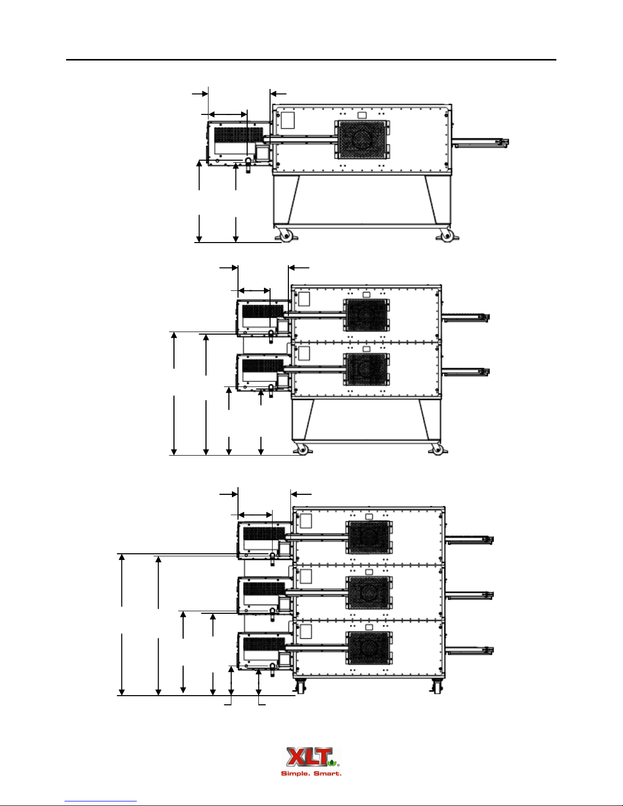
Gas & Electrical Connection Dimensions - Australian & World Ovens
For Models 1832, 2440, 3240, 3255 & 3855
18.91
[480]
12.35
[314]
24.88
[632]
25.24
[641]
18.91
[480]
12.35
[314]
11
49.82
[1265]
44.87
[1140]
50.18
[1275]
29.83
[758]
45.23
[1149]
12.35
[314]
30.19
[767]
24.88
[632]
25.24
[641]
18.91
[480]
9.85
[250]
10.21
[259]
NOTE: All dimensions in inches [mm].
12
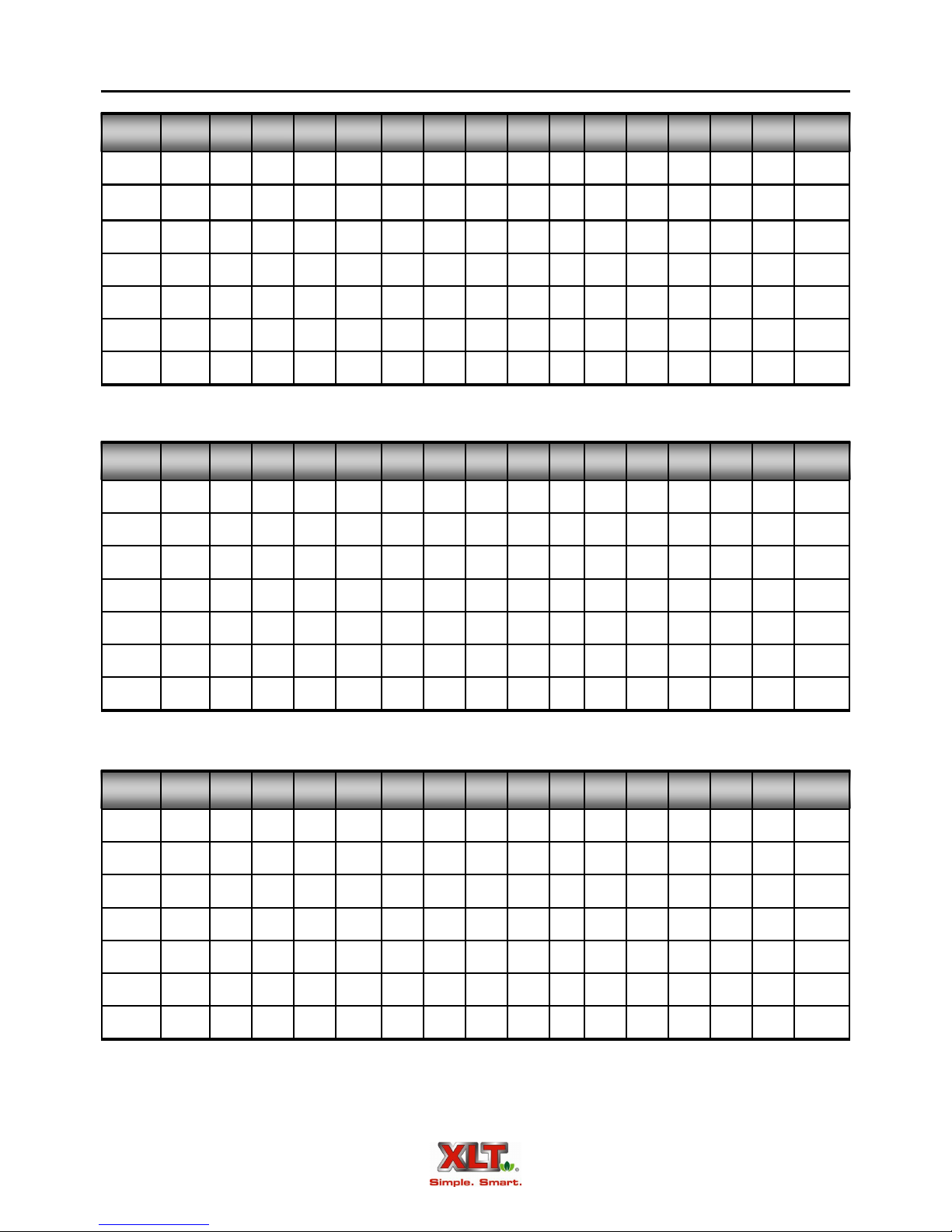
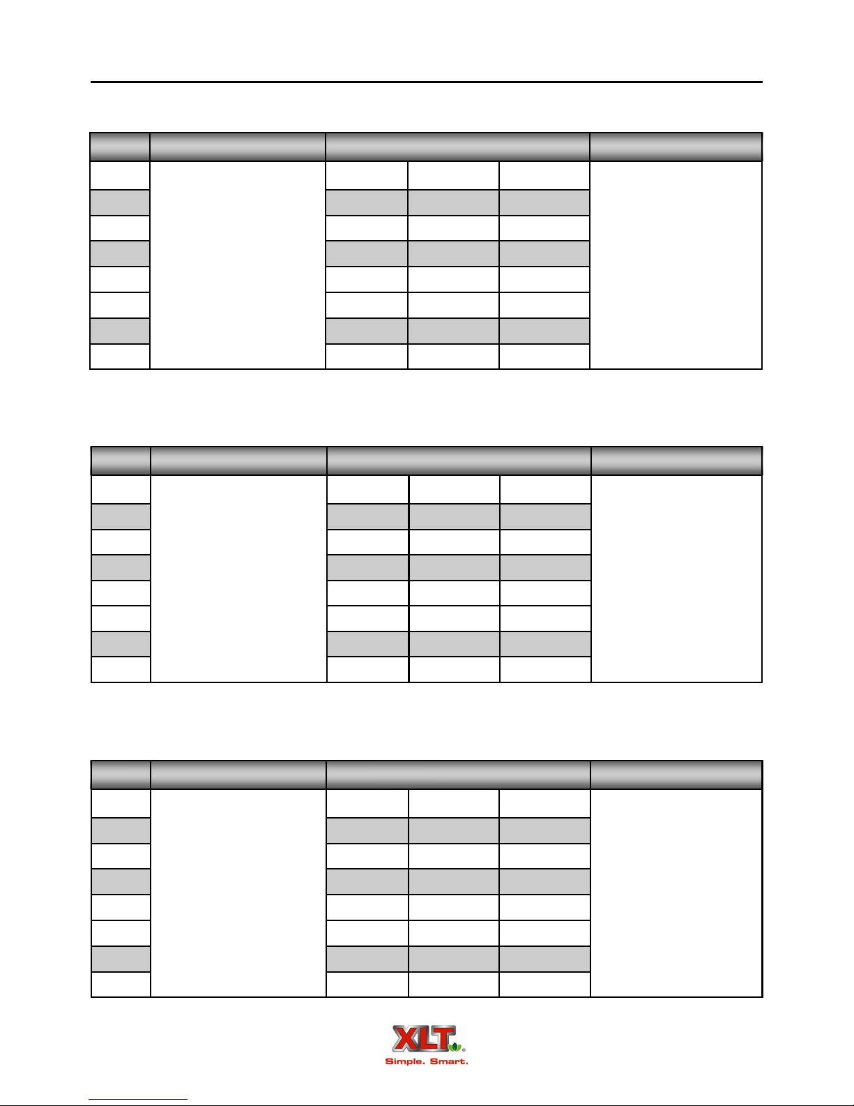
Oven Electrical Requirements
Australian Ovens
OVEN VOLTS AMPS FREQUENCY
Size
1832 3 6 9
2440 3 6 9
3240 3 6 9
220/230/240 VAC
3255 3 6 9
3270 6 12 18
3855 3 6 9
3870 6 12 18
Single Double Triple
50 Hz
Standard Ovens
OVEN VOLTS AMPS FREQUENCY
Size
1832 6 12 18
2440 6 12 18
3240 6 12 18
120 VAC
3255 6 12 18
3270 12 24 36
3855 6 12 18
3870 12 24 36
Single Double Triple
60 Hz
World Ovens
OVEN VOLTS AMPS FREQUENCY
Size
1832 3 6 9
2440 3 6 9
3240 3 6 9
220/230/240 VAC
3255 3 6 9
Single Double Triple
50 / 60 Hz
3270 6 12 18
3855 3 6 9
3870 6 12 18
Gas Requirements Australian, Standard. & World
Oven Burner Max. Capacity NAT Gas LP Gas
Size BTU/HR KW/HR MJ/HR W/C mbar kPa W/C mbar kPa
1832 52,000 15.24 63 6-14 15-35 1.5-3.5 11.5-14 27.5-35 2.75-3.5
2440 65,000 19.05 79 6-14 15-35 1.5-3.5 11.5-14 27.5-35 2.75-3.5
3240 90,000 26.37 105 6-14 15-35 1.5-3.5 11.5-14 27.5-35 2.75-3.5
3255 150,000 43.95 169 6-14 15-35 1.5-3.5 11.5-14 27.5-35 2.75-3.5
3270 160,000 46.88 190 6-14 15-35 1.5-3.5 11.5-14 27.5-35 2.75-3.5
3855 150,000 43.95 169 6-14 15-35 1.5-3.5 11.5-14 27.5-35 2.75-3.5
3870 160,000 46.88 190 6-14 15-35 1.5-3.5 11.5-14 27.5-35 2.75-3.5
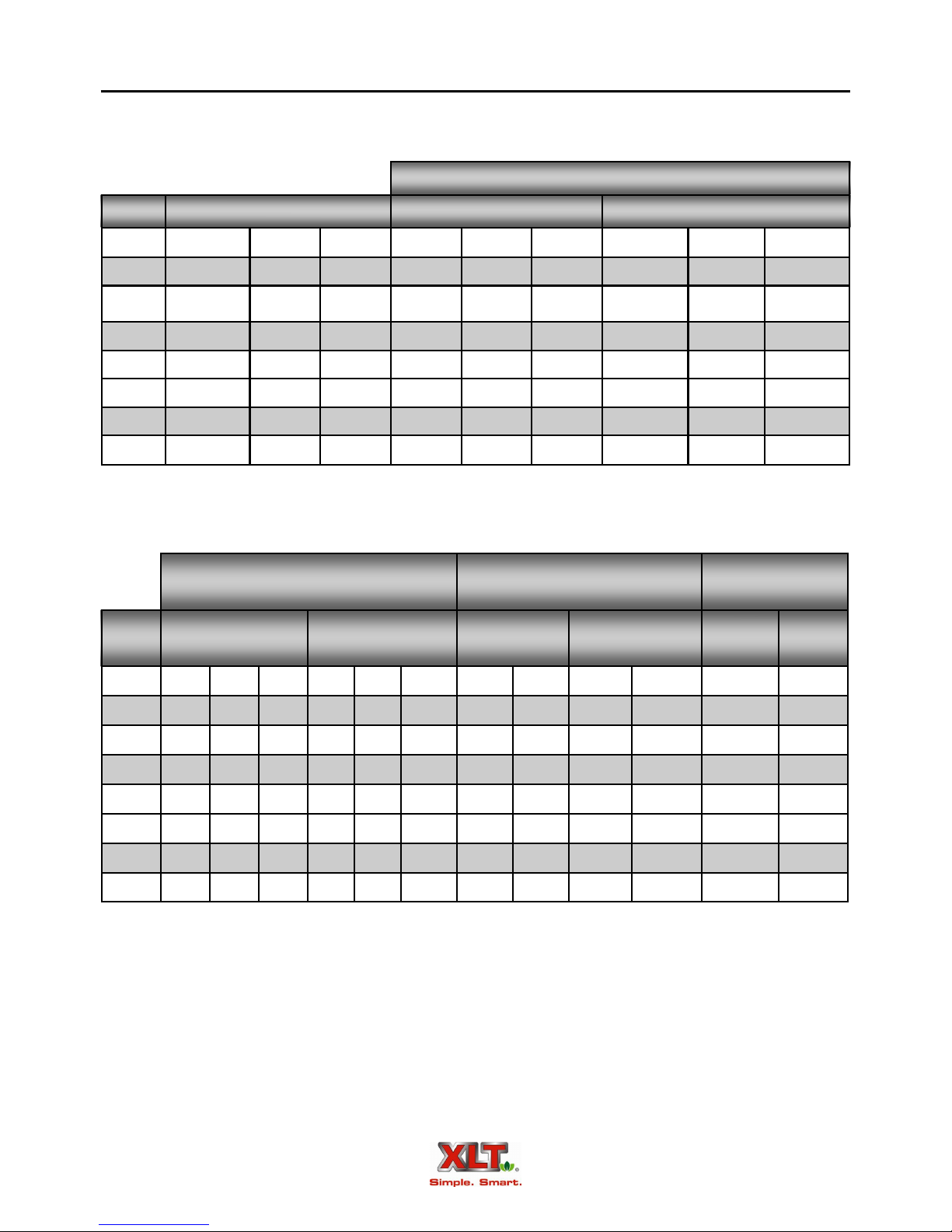
Inlet Pressure
13
Manifold Pressure
Orifice Sizes
Standard & World
Oven Natural Gas LP Gas Natural Gas LP Gas Natural
Size W/C mbar kPa W/C mbar kPa Inches MM Inches MM MM MM
1832 3.5 8.75 .875 10 25 2.5 .1285 3.26 .0820 2.08 3.56 2.24
2440 3.5 8.75 .875 10 25 2.5 .144 3.66 .0890 2.26 3.96 2.44
3240 3.5 8.75 .875 10 25 2.5 .1695 4.3 .1040 2.64 4.62 2.79
3255 3.5 8.75 .875 10 25 2.5 .219 5.56 .1285 3.26 5.94 3.66
3270 3.5 8.75 .875 10 25 2.5 .147 3.73 .0980 2.49 4.39 2.64
3855 3.5 8.75 .875 10 25 2.5 .219 5.56 .1285 3.26 5.94 3.66
3870 3.5 8.75 .875 10 25 2.5 .147 3.73 .0980 2.49 4.39 2.64
Orifice Size
Australia
LP
Gas
Gas
All values shown this page are per each oven
14
Gas Group I2H I2E I
World Oven Gas Group
Natural Gas Propane Gas
I2L I3+ I
2E+
3B/P (30)
I
3P
(30/37/50)
I
Inlet pressure (mbar) 20 20 20/25 25 28/30/37/50 28-30/37/50 30/37/50 37
Number of injectors (1) per burner
Main burner opening size Fixed
Ignition Electric Direct Spark Igniter
Inlet connection
BSP 3/4" male thread
Gas Matrix by Country
Natural Gas (8.75 mbar manifold) LP Gas (25 mbar manifold)
3B (37)
Country Symbol
I2H I2L I2E I
I
2E+
I3+ I3P
3B/P
Germany DE X X X
Austria AT X X
Belgium BE X X
Denmark DK X X
Spain ES X X X
Finland FI X X
France FR X X X X
Greece GR X
Ireland IE X X X
Iceland IS
Italy IT X X
Luxembourg LU
Norway NO X
Netherlands NL X X X
Portugal PT X X X
United Kingdom GB X X X
Sweden SE X X
Switzerland CH X X X X
Slovenia SI X
Slovakia SK X
Cyprus CY X X X
Estonia EE X
Latvia LT X
Lithuania LV
Malta MT X X
Hungary HU X X
Poland PL X
Czech Republic CZ X X
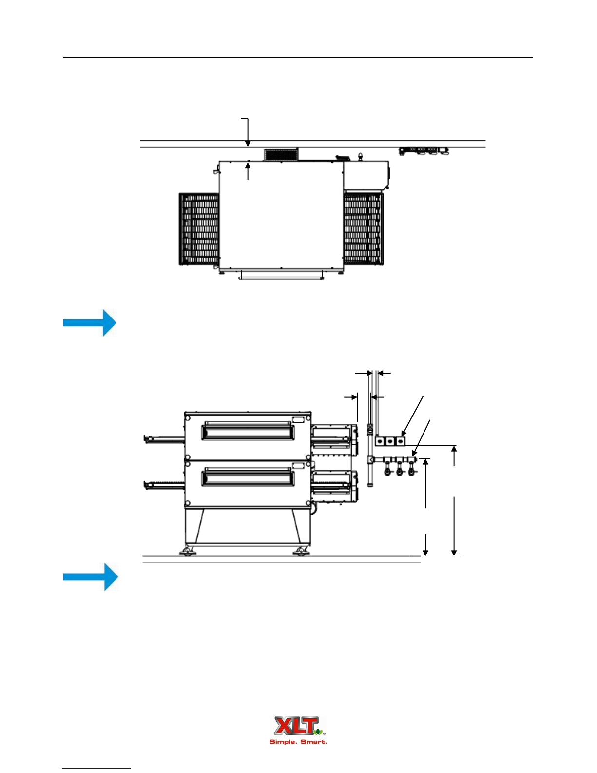
Oven Only Rough-In Specifications
The gas supply and the electrical supply are to be provided by the customer prior to installation. The picture shows a typical utility rough-in for a triple stack oven. Preparing the utilities
this way allows for an easy third deck addition if a double stack oven is initially installed.
6.00 [152]
From back of oven to wall
Utilities must be easily accessible when the ovens are in the installed position. Do not install utilities
behind the ovens.
NOTE
15
3.00
6.00
[76]
[152]
1. All dimensions in inches [mm].
2. All dimensions on this page are recommended.
Electrical Supply
Gas Manifold
48.00
[1219]
42.00
[1067]
NOTE
All installations must conform to local building and mechanical codes. It is required that
the ovens be placed under a ventilation hood. The gas supply should have a gas meter and regulator large enough to handle all of the gas appliances, such as the furnace, hot water heater, and ovens, in operation at the same time. Add up all of the BTU / kw / MJ ratings to determine the total
load. (See Oven Specifications page for supply requirements).
16
Oven Only Rough-In Specifications
FOR EACH OVEN:
Electrical service for Standard Ovens must be 120VAC, 20 A, 60 Hz single phase circuits
with ground.
Electrical service for World Ovens must be 220/230/240VAC, 10 A, 50/60 Hz single phase
circuits with ground.
Electrical service for Australian Ovens must be 220/230/240 VAC, 10 A, 50Hz single
phase and installed in accordance with the latest version of AS/NZS 3000 wiring rules.
A separate circuit breaker must be provided for each oven deck.
Gas and electric connections must be accessible when the ovens are in the installed position.
Electrical plugs and cords must meet all local code requirements.
Do not use Teflon tape on gas line connections as this can possibly cause gas valve
malfunction or plugging of orifices from shreds of tape. Use of Teflon tape may af-
CAUTION
fect warranty.
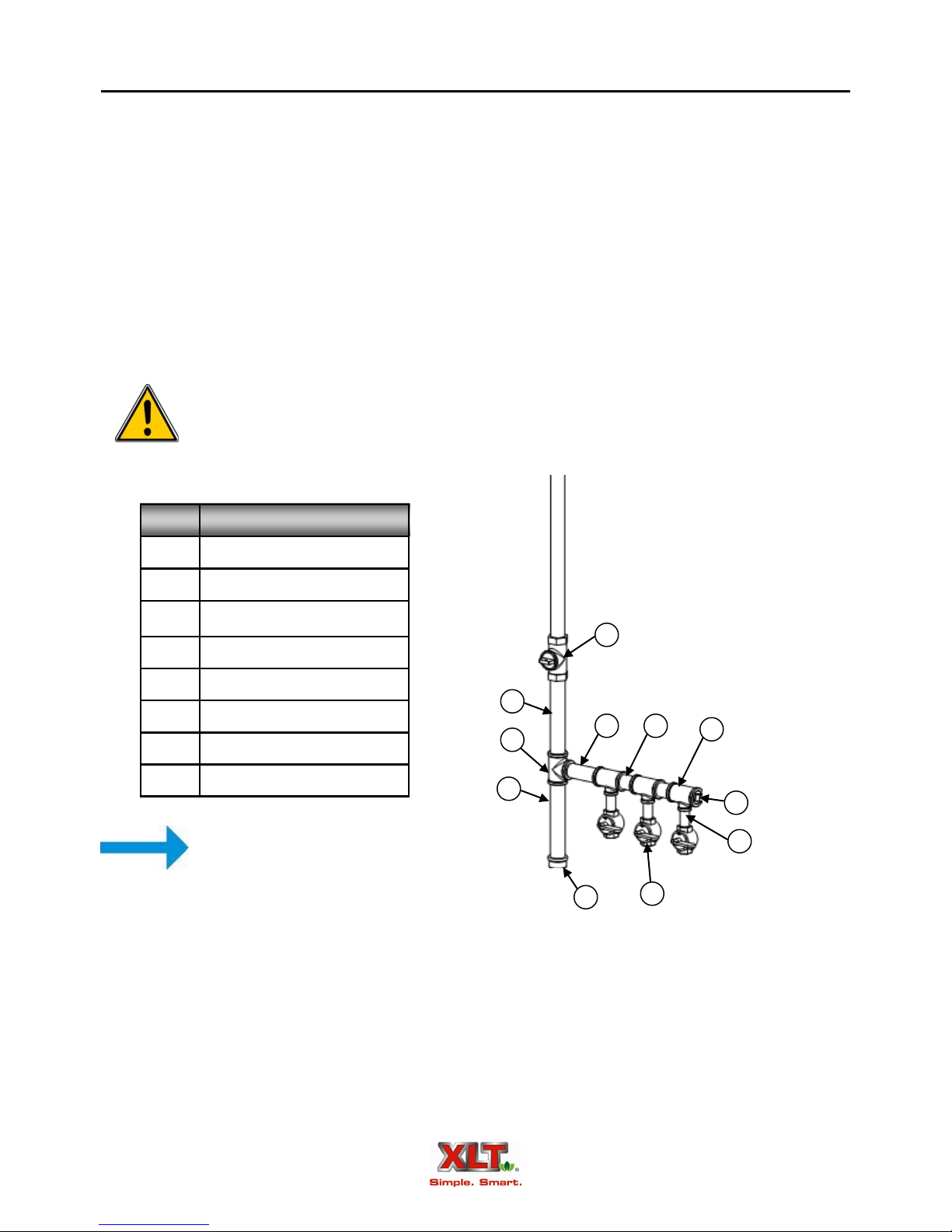
Item # Description
1 1-½ [40] Shut-Off Valve
2 ¾ [20] Shut-Off Valve
3 6 [150] Nipple
1
4 ¾ [20] Nipple
5 Reducing Tee
3
6 Tee
7 Cap
8 Plug
6
3
3
4
5
8
All pipe fittings to be 1-½ [40] minimum
4
unless noted. NPT & BSP
NOTE
7
2
Gas hose assemblies with quick disconnects for each oven deck will be installed at each valve.
NOTE: All dimensions in inches [mm].
Oven Assembly
17
WARNING & SAFETY INFORMATION
XLT ovens can easily be moved and stacked with the proper lifting equipment. The use of
lifting equipment is highly recommended.
These ovens are heavy and can tip or fall causing bodily injury.
NEVER place any part of your body beneath any oven that is suspended by the
lifting jacks. A crush hazard exists if the oven falls or slips.
DO NOT place your hands on the lifting jack vertical pole beneath the jack’s
WARNING
CAUTION
winch. As the jack’s winch descends when you turn the jack handle, a pinch
point is created between the winch and the pole.
BE CAREFUL when rolling the oven on the cart, especially when going up or down
ramps and over bumps. Leave the straps/banding on until the oven is near the assembly area.
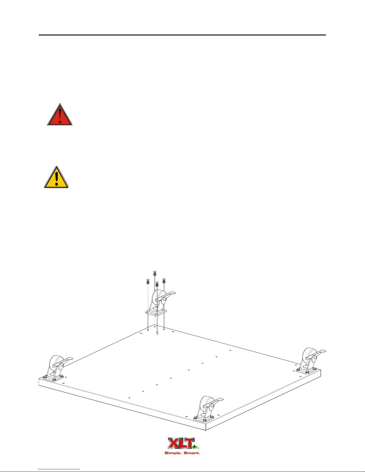
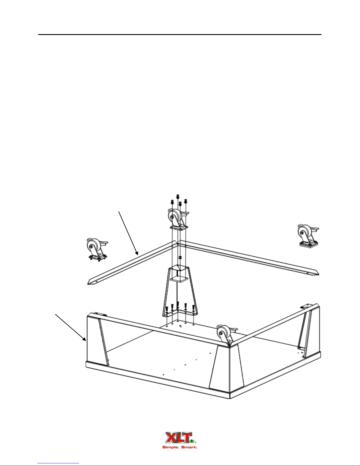
Base Assembly - Triple Stack
1. Flip the oven base upside down on the floor.
2. For triple-stack configurations, attach the four casters directly to the base with the supplied
3/8" x 1" hex bolts, washers, and lock-washers.
3. Flip the base assembly over and ensure the insulation is placed properly.
18
Oven Assembly
Base Assembly - Single & Double Stack
1. Flip the oven base upside down on the floor.
2. For single and double-stack configurations, attach the four legs to the bottom of the base with
the supplied 3/8" x 1" hex bolts, washers, and lock-washers. Do not fully tighten them at this
time. Leave them slightly loose so that the rest of the components can be more easily assembled.
3. Place the four leg angles on top of the legs as shown. All of the leg angle holes should line up
with the holes in the bottom of the legs. Place two (2) washers on each leg at the inner corner
holes. These 2 washers are approximately the same thickness as the leg angles, and will keep
the caster level.
4. Attach the four casters to the legs as shown. The leg angles and washers are sandwiched between the casters and the leg base plates.
5. Tighten all fasteners.
6. Flip the base assembly over and ensure the insulation is placed properly.
Leg
Leg Angle
Oven Assembly
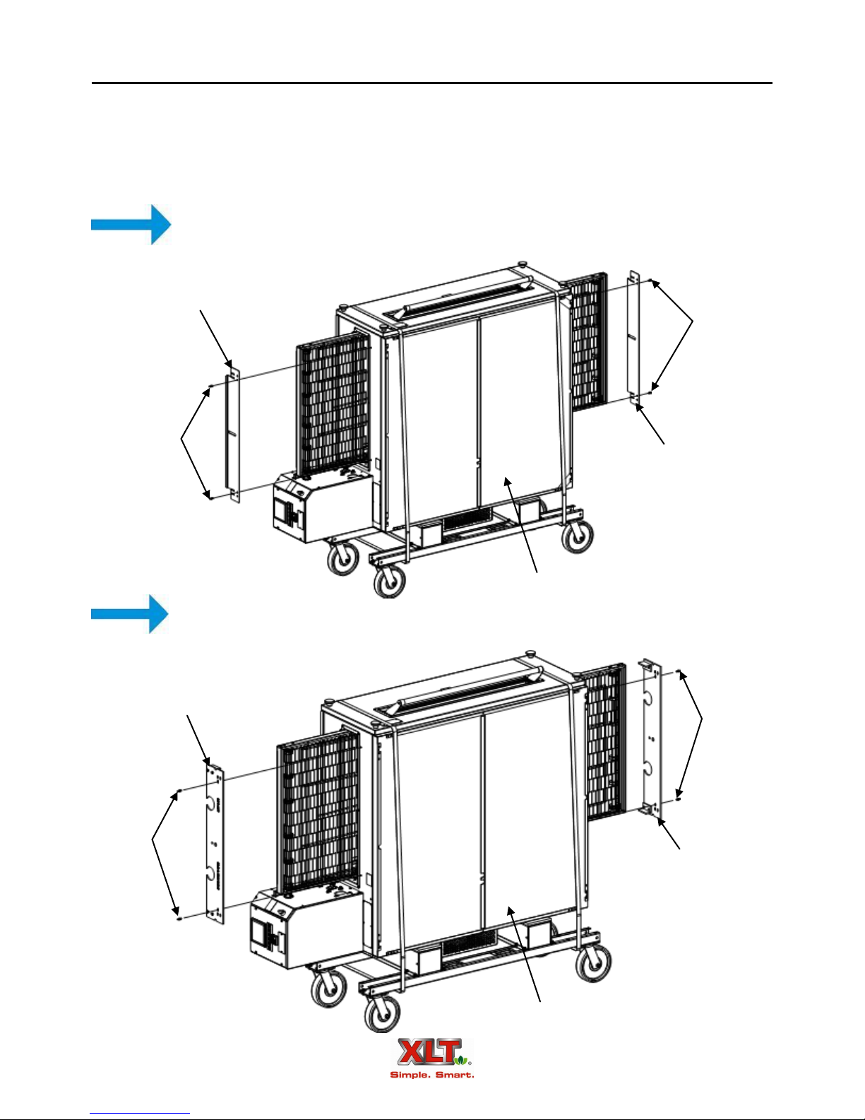
Prepare the Oven for Lifting
1. Remove the two conveyor opening flaps and thumbscrews from the oven. Set them aside for
reinstallation later.
2. Install the lifting plates in place of the conveyor opening flaps using the same thumbscrews.
If using an AVI Hood System, conveyor flaps are not needed.
NOTE
Conveyor
Opening Flap
Thumb
Screws
Thumb
Screws
Conveyor
Opening Flap
19
NOTE
Right Hand
Lifting Plate
Thumb
Screws
Top of Oven
The Lifting Pipe hole, marked for the appropriate oven size, must be installed closest
to the control box.
Thumb
Screws
Left Hand
Lifting Plate
Top of Oven

20
Oven Assembly
Lifting Jack Setup
Each lifting jack consists of two (2) parts; the pole/winch assembly, and the tripod base.
1. Place the bottom of the pole into the socket of the tripod base.
Make sure that the notch on tube of the winch assembly is aligned with the pin
in the tripod base as shown. These alignments are important and keep the jack
aligned properly.
WARNING
2. Insert the lifting pipe through the oven bake chamber. Make sure the pipe is centered.
Check for smooth operation. The cable should not be pinched and should pass
smoothly over the pulley on top of the pole assembly.
Inspect cable prior to each use.
If cable is frayed or shows signs of excessive wear and tear, DO NO USE until
cable is replaced.
At a minimum replace the cable annually with wire rope that meets or exceeds
the jack manufacturer’s specifications.
Do not exceed the stated capacity of the jack.
Jack
Top of Oven
Front of Oven
Lifting Pipe
Cart
Bands
Illustrations shown with XLT Oven on Cart, instructions also apply when oven is crate shipped.
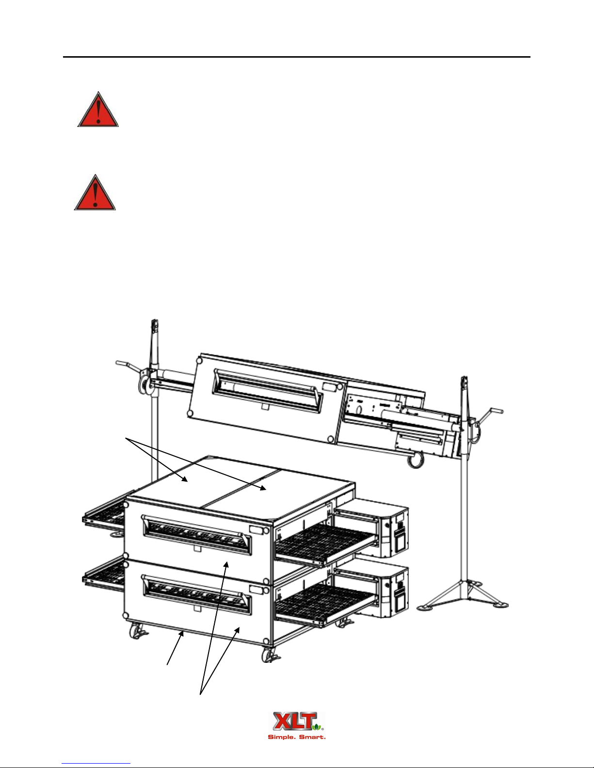
Oven Assembly
Stacking the Ovens
1. Fully insert the lifting jacks into the lifting pipe.
Failure to engage properly can result in damage, injury, or death from a falling
oven.
WARNING
2. Raise the oven high enough to clear the cart or the skid.
Both jacks should be raised in unison, otherwise they may bind and a dangerous
situation may develop.
Do not put any part of yourself under the oven at any time.
WARNING
3. Remove the cart or skid.
4. Rotate the oven as shown.
5. Roll the appropriate oven base underneath the oven.
6. Lower the oven onto the base.
7. Repeat as necessary
The oven is top heavy. Be careful!
21
Insulation
Base Assembly
Installed Oven Decks

22
Oven Assembly
Stacking the Ovens
8. Reinstall the conveyor opening flaps in each oven deck. A series of holes in the flaps allow
adjustment for different heights of food product.
9. Control box heat shields need to be installed on any multi-deck installation. For xx70 models,
they are required on both ends. To install, remove the four (4) control box screws under the
conveyor. Place the panel with the notch towards the bake chamber. Line up the slots with the
existing holes and replace the screws.
Conveyor Opening Flap
Thumb Screws
Lower Control Box Plate Notch
Lower Control Box Plate
Control Box Screws
Oven Installation
Electric Supply Requirements for Australian, Standard. & World Ovens
Australian Ovens
In Australia, the electrical service must be installed in accordance with the latest
CAUTION
HIGH
VOLTAGE
version of AS/NZS 3000 wiring rules.
Standard Ovens
Electrical Grounding Instructions
This appliance is equipped with a three-prong (grounding) plug for your protection against shock hazard and should be plugged into a properly grounded
three-prong receptacle. Do not cut or remove the grounding prong from this
plug.
When installed, the appliance must be electrically grounded in accordance with
local codes, or in the absence of local codes, with the National Electrical Code,
ANSI/NFPA 70, or the Canadian Electrical Code, CSA C22.2, as applicable.
World Ovens
23
This appliance is equipped with a ground lug for your protection against shock
hazard and must be properly grounded.
When installed, the appliance must be electrically grounded in accordance with
local codes.
Physical Location & Spacing Requirements
XLT Ovens are suitable for installation on either combustible or non-combustible floors,
and adjacent to either combustible or non-combustible walls. The motor cover is designed to provide the proper clearance to the back of the oven. The minimum side clearances are 6in. / 150mm,
measured from the end of the conveyor.
All installations must conform to local building and mechanical codes.
NOTE
24
Oven Installation
Gas Supply Requirements for Australian, Standard. & World Ovens
The gas supply shall have a gas meter and regulator large enough to handle all of the gas
appliances, such as the furnace, water heater, and ovens in operation at the same time. Add up all
of the Btu/kw/MJ ratings to determine the total load. The installation must conform to local building codes.
1. The appliance and its individual shutoff valve must be disconnected from the gas supply piping system during any pressure testing of that system at test pressures in excess of 3.5 kPa or
½-psi.
2. The appliance must be isolated from the gas supply piping system by closing its individual
manual shutoff valve during any pressure testing of the gas supply piping system at test pressures equal to or less than 3.45 kPa or ½-psi.
Minimum and maximum inlet pressures are as follows:
Gas Type Min kPa Max kPa Min “WC Max “WC
Natural 1.5 3.5 6.0 14
LP 2.75 3.5 11.5 14
For Australia, if installing with a flexible hose assembly, the assembly must be certified to
AS/NZS 1869, and be Class B or D.
For Standard Ovens, if installing with a flexible gas hose, the installation must comply with
either ANSI Z21.69 or CAN/CGA-6.16 and a disconnect device complying with either ANSI
Z21.41 or CAN-6.9.
The installation must conform with local building codes, or in the absence of local codes, with
the National Fuel Gas Code, ANSI Z223.1, latest version, Natural Gas Installation Code, CAN/
CGA-B149.1, or the Propane Installation Code, CAN/CGA-B149.2, as applicable.
All installations must conform to local building and mechanical codes.
NOTE
Oven Installation
25
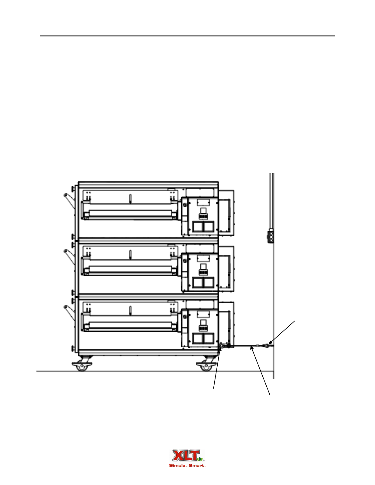
Restraint
Because all ovens are equipped with casters, all installations must be configured with a restraint to limit the movement of the oven without depending on the gas connector and quickdisconnect device or its associated piping, and the electric power supply cord to limit the oven
movement. One (1) restraint kit, which includes two (2) eye bolts and a cable, is required for each
oven stack, regardless if used on a single, double, or triple configuration. The machine eye bolt
should be installed in the lowest hole of the back wall on the control end of the lowest oven in the
stack. The lag eye bolt must be installed into a structural member of a wall.
Upon completion of performing any service or cleaning functions that require removal of
the restraint, insure that it is correctly re-attached to the oven. In Australia, install the restraint cable in accordance with AS 5601, latest version.
Lag Eye Bolt
Machine Eye Bolt
Restraint Cable
(shown fully extended)
26
Oven Installation
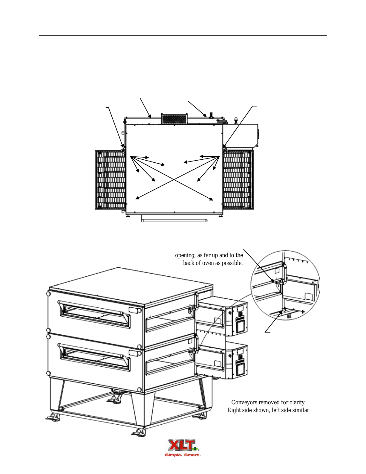
Fire Suppression
The requirement for fire suppression systems vary by location and the authority having jurisdiction. Contact XLT Ovens for fire suppression kit availability. Crumb trays and chain guards
must be removable without disturbing fire suppression piping.
Supply Line
Aim nozzles at
center of oven
Supply Inlet
Aim nozzles at
center of oven
Place nozzles into conveyor
opening, as far up and to the
back of oven as possible.
Conveyors removed for clarity
Right side shown, left side similar
Connect supply lines
under lower control
box and across back
of ovens

Ventilation Requirements & Guidelines
27
Ventilation Requirements
Most gas burning appliances produce CO (carbon monoxide), a poison. CO and heat must
be vented to the outside. A powered ventilation hood is required to remove these. The hood and
HVAC installation must meet local building and mechanical codes. In Australia, a ventilation
hood should be installed in accordance with AS5601 Gas Installation. Requirements vary through-
out the country depending on the location by city. Proper ventilation is the oven owner’s responsi-
bility. The AVI Hood system is designed to meet all requirements on XLT ovens and it is our recommendation that this system be used.
Ventilation Guidelines
Obtain information from the authority having jurisdiction to determine the requirements for
your installation. Your ventilation hood supplier and HVAC contractor should be contacted to
provide guidance. An air balance test is highly recommended, performed by a licensed contractor.
A properly engineered and installed ventilation hood and HVAC system will expedite approval,
reduce oven maintenance cost, and provide a more comfortable working environment.
Ventilation Performance Test
After the oven and ventilation hood have been installed and are operating, a smoke candle
can be used to “see” if the heat and products of combustion are being properly exhausted. Smoke
candles can be purchased through HVAC contractors. The test procedure is outlined below.
The oven must be operating at 450º-500ºF / 232º-260ºC.
The conveyor must be turned off.
The ventilation hood exhaust fan must be turned on.
Put a smoke candle in a pan on the conveyor belt at the center of the oven.
Observe the smoke pattern coming out of the oven.
The ventilation hood must capture all of the smoke from the oven. An air balance test can
help determine the proper amount of exhaust and make-up air flow rates.
Oven & Hood Interlock
An interlock system between the oven and hood is highly recommended and is required in
some jurisdictions. AVI hoods have this feature.
28
Ventilation Requirements & Guidelines
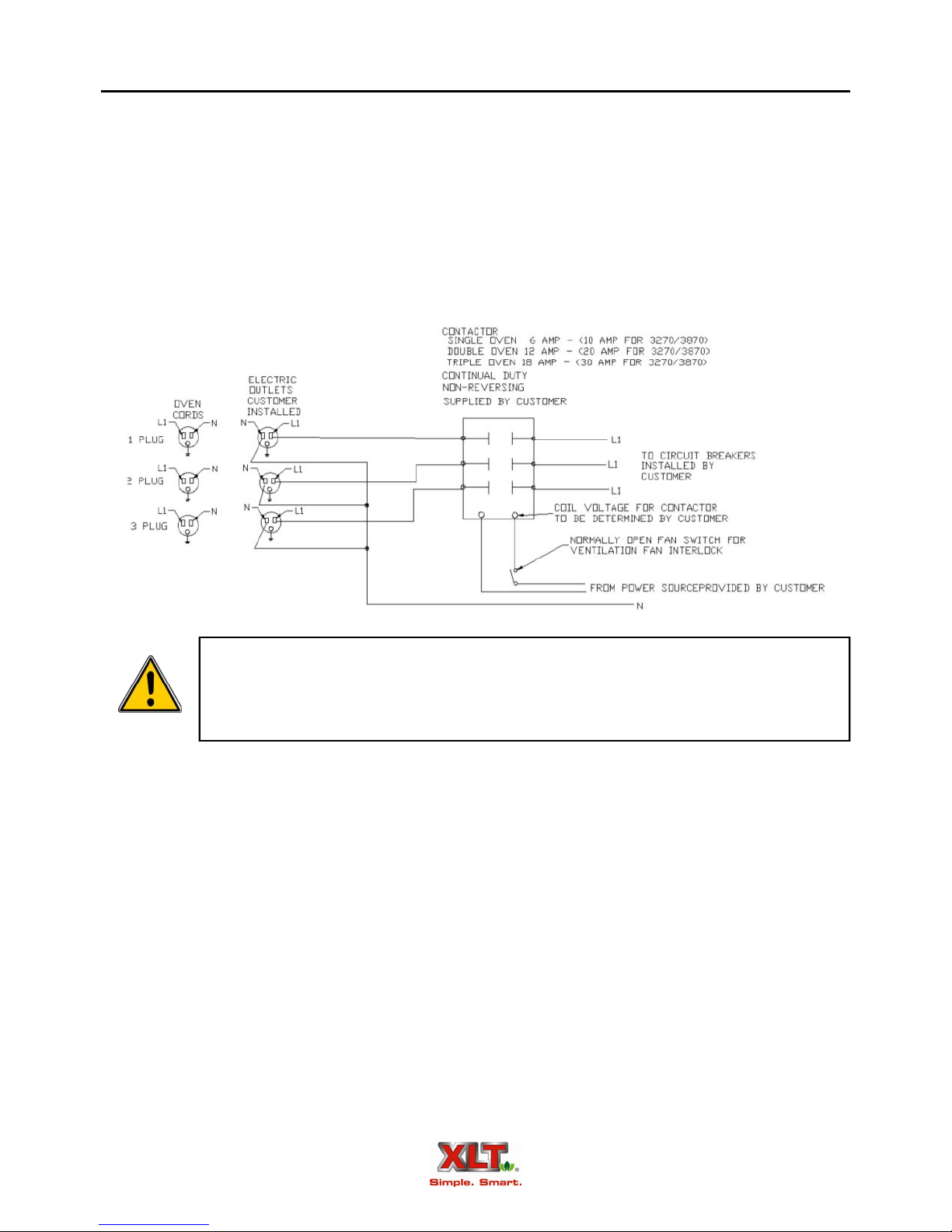
Non-AVI Hood Interlock
The following is a recommended method of providing an interlock system (if required),
between the exhaust fan and ovens. The circuit shown will stop the ovens from operating if the
exhaust fan fails and also prevent the ovens from starting if the exhaust fan is not first operating. It
is recommended that the fan interlock switch be located on the exhaust fan itself rather than the
motor to prevent a false run signal in the case of a broken fan drive belt. It is the customer’s re-
sponsibility to have the interlock system installed by a licensed electrician and that it meets all required local codes.
Always use the proper oven shut down procedure for turning ovens off. Do not
turn off the exhaust fan until cool down sequence on oven is completed. The use
of the exhaust fan control to shut off ovens manually may void the warranty on
CAUTION
ovens.
Oven Initial Start-Up
All XLT ovens are test-fired at the factory. Operation is verified, and adjustments are
made to ensure proper function. However, field conditions are sometimes different than factory
conditions, such as voltage and fuel pressure. These variables make it necessary to have an authorized service technician verify operation and make field adjustments if needed. The following
items must be checked and verified to meet the specifications and requirements stated in this manual prior to the oven being commissioned:
Fuel line pipe size
Fuel pressure (static)
Fuel pressure (dynamic)
Proper electrical connections
Proper ventilation
The following Initial Start-Up Checklist must be completed (both sides) at time of installation,
signed by the Customer and returned to XLT Ovens to initiate Warranty Policy.

Oven Initial Start-up Checklist - Remove & Return to XLT Ovens
Date of installation: ______________________________
Installed by: XLT installer: ______________________
Other: Company:____________________
Installer: ____________________
Phone #: ____________________
Facility Information
Store Name: ___________________________________
Physical Address: ______________________________
City: ____________________ State: _____ Zip:_______
Phone #: ______________________________________
E-mail: _______________________________________
Contact Person: ________________________________
Freestanding Strip Mall New construction
Electrical
Electrical supply accessible after installation: YesNo
Separate electrical circuit per oven: Yes No
Electrical Supply (per oven): _______ Volt _____ Amp
_______Hz _____ Phase
Gas N/A
Inlet Pressures: Static: _________________ ” W/C
Dynamic (full burn): _________________ ” W/C
Existing location Remodel
Gas Line Size: ___________ Teflon Tape: Yes No
Oven Location: Against wall In corner Island
I&O Manual presented to store operator: Yes No
Utilities present at installation: Electric Gas
On-Site dough prep: Yes No
Air-born contaminates: Flour Cornmeal Grease
Other _________________________________
HVAC/Contractor Contact:_______________________
Address: ______________________________________
City: ____________________ State: _____ Zip:_______
Phone #: _______________ Cell: __________________
E-mail: _______________________________________
Restraint Cable Installed (bottom oven): Yes No
Customer or store operator shown how to disassemble and
clean ovens and hood: Yes No ________________
Test cook performed: Yes No ________________
Ovens ran for 20 min. Yes No ________________
All features explained: Yes No ________________
Damage to ovens or hood during shipment or installation:
______________________________________________
Missing parts: __________________________________
Customer Signature: _____________________________
List all gas appliances in store (with gas requirements)
XLT Oven #1 __________________________________
XLT Oven #2 __________________________________
XLT Oven #3 __________________________________
______________________________________________
______________________________________________
______________________________________________
______________________________________________
Total gas requirements for store: ___________________
Regulator Capacity: _____________________________
Meter Capacity: ________________________________
Shut off valve accessible after installation: Yes No
One shut off valve per oven: Yes No
Gas line purged of air prior to installation: Yes No
Fittings tested for gas leaks: Yes No
Results: _______________________________________
Ventilation
Hood manufacturerAVI Other (specify)
_____________________________________________
Interlock system for non-AVI hood: Yes No
Air balance test performed: Yes No
Smoke test preformed: Yes No
Return to: XLT Ovens
PO Box 9090
Wichita, KS 67277
FAX: 316-943-2769
Oven Size: 1832 2440 3240 3255
3270 3855 3870
Heat Source: Natural Gas LP Electric

Oven Initial Start-up Checklist - Remove & Return to XLT Ovens
Bottom Oven N/A
Model #: __________________________________
Serial #: __________________________________
Thin Crust Thick Crust Pan Screen
Other Product: ____________________________
Front Belt Speed: _______min ______sec
Back Belt Speed: _______min ______sec N/A
Good Belt Tension: Yes No
Conveyor Belt Direction: L to R R to L
Set Point Temp: Left ________ Right _________
Fingers in proper location: Yes No
Crumb Trays: Solid Perforated None
Fire Suppression Installed: Yes No
Right Burner: Square Round
Main Shutter Setting: _______________________
Secondary Shutter Setting: ___________________
Low flame after temperature drop: Yes No
Was Combination Valve adjusted: Yes No
High Bias: ___________ Low Bias: ___________
Left Burner: N/A
Main Shutter Setting: _______________________
Secondary Shutter Setting: ___________________
Low flame after temperature drop: Yes No
Was Combination Valve adjusted: Yes No
High Bias: ___________ Low Bias: ___________
Middle Oven N/A
Model #: __________________________________
Serial #: __________________________________
Thin Crust Thick Crust Pan Screen
Other Product: ____________________________
Front Belt Speed: _______min ______sec
Back Belt Speed: _______min ______sec N/A
Top Oven
Model #: __________________________________
Serial #: __________________________________
Thin Crust Thick Crust Pan Screen
Other Product: ____________________________
Front Belt Speed: _______min ______sec
Back Belt Speed: _______min ______sec N/A
Good Belt Tension: Yes No
Conveyor Belt Direction: L to R R to L
Set Point Temp: Left ________ Right _________
Fingers in proper location: Yes No
Crumb Trays: Solid Perforated None
Fire Suppression Installed: Yes No
Right Burner: Square Round
Main Shutter Setting: _______________________
Secondary Shutter Setting: ___________________
Low flame after temperature drop: Yes No
Was Combination Valve adjusted: Yes No
High Bias: ___________ Low Bias: ___________
Left Burner: N/A
Main Shutter Setting: _______________________
Secondary Shutter Setting: ___________________
Low flame after temperature drop: Yes No
Was Combination Valve adjusted: Yes No
High Bias: ___________ Low Bias: ___________

Low Flame Bias
Adjustment (5mm)
Combination Gas Valve
Manifold Pressure
Adjustment (High
Flame Bias Screw
(Brass Nut– 8mm)
Oven Initial Start-Up
Inlet Pressure Tap
Manifold
Pressure Tap
31
Secondary
Shutter
Main Shutter
Low Flame Bias
Adjustment (5mm)
Manifold Pressure Adjustment High
Flame Bias Screw (Brass Nut 8mm)
Combination
Gas Valve
Quiet Fire
Direct Ignition Burner
Inlet Pressure Tap
Manifold
Pressure Tap
Contact XLT Ovens or your designated representative to make all gas pressure adjustments.
Direct Ignition Burner

32
Manifold Pressure
Regulator (under
cap screw)
Oven Initial Start-Up
Manifold
Pressure Tap
Combination
Gas Valve
Inlet Pressure Tap
Direct Ignition Burner - Australia
Contact XLT Ovens or your designated representative to make all gas pressure adjustments.

Left
Oven Operator Controls
Models 1832, 2440, 3240, 3255 & 3855
Single oven shown, Double and Triple Stack similar
Right
Front
Conveyor Speed
Control
33
Oven
Switch
Circuit Breakers
Fan & Filter
Control Panel
Standard Belt
Back
Left Right
Temperature
Control
Back Conveyor
Speed Control
Front
Conveyor
Speed
Control
Front
Control Panel
Split Belt

34
Left
Oven Operator Controls
Models 3270 & 3870
Single oven shown, Double and Triple Stack similar
Right
Front
Circuit Breakers
Oven
Switch
Fan & Filter
Left Side Control Panel
(Standard & Split Belt)
Back
Left Right
Front
Left Side
Temperature
Control
Front
Conveyor
Speed
Control
Right Side
Temperature
Control
Right Side Control Panel
Standard Belt
Back
Conveyor
Speed
Control
Right Side Control Panel
Split Belt

Oven Operation
35
This oven is not capable of being safely placed in operation in the event of a
power failure. No attempt should be made to operate this oven during power
failure.
CAUTION
1. Turn the switch on. The fan(s) will energize, the temperature and conveyor control will light
up, and the conveyor will start to move.
2. Adjust the temperature controller set-point to the desired temperature. To change the oven setpoint temperature, press and hold either the UP or DOWN key. The keys needs to be depressed for at least 2 seconds. After UP or DOWN key inactivity, the display will blink once
indicating that the set point temperature has been set. The FUNC and MAN keys are used at
the factory to program the variables in the controller. It is recommended that the FUNC and
MAN keys be left alone. If either of these keys has been pressed, simply press them again until the display matches the Figure shown. It may take several key-presses to cycle through all
the variables.
3. Adjust the conveyor control to the desired belt time. To change the belt time, press and hold
either the UP or DOWN key.
4. To turn the conveyor ON or OFF, push both arrow keys simultaneously.
5. Allow about 30-45 seconds for the burner to ignite. You should hear combustion and see the
indicated temperature rise.
6. If the burner does not ignite, turn the switch off, wait five (5) minutes, and repeat step 1. If it
does not light after three (3) attempts, please see the troubleshooting section of this manual.
7. Allow about 30 minutes for the oven to reach the desired temperature.
8. To turn the oven off, turn the switch to the off position. Do not unplug the oven from electrical
power. The oven is equipped with an automatic cool down feature that allows the fan to run
until the oven is cooled to a safe level (approximately 30 minutes).
NOTE
Belt Time
(MIN: SEC)
Up and Down
Arrow Buttons
Up Key
Down Key
Temperature Control
Actual
Temperature
Set Point
Temperature
6:30
Conveyor Control
The Conveyor Control is factory preset at 1:30 minute minimum and 17:00 minutes
maximum. If a belt time is desired that is outside these limits, contact XLT Ovens for
proper service procedures.

36
Oven Cleaning
As with any appliance, periodic cleaning and maintenance is required. Many factors affect
this schedule such as product mix and hours of usage. An example schedule is included.
Your XLT oven is constructed of stainless steel. Most commercial cleaning agents may be
used safely on all stainless steel surfaces. Check application restrictions on product label prior to
usage. Observe recommended precautionary and safety measures as dictated by the product manufacturer.
Do not use abrasive cleaners or abrasive pads as they can scratch stainless steel surfaces.
Example Cleaning Schedule for XLT Ovens
Task Daily Weekly Monthly Semi- annual
Wipe down front
Clean sandwich window
Wipe down sides
Wipe down top
Wipe down control box
Wipe down motor cover
Empty Crumb Trays
Remove large debris from conveyor
Clean / replace cooling fan filters
Clean finger covers
Clean bake chamber floor
Clean bake chamber walls
Clean bake chamber top
Clean inside of face panel
Clean control box sides and top
Clean control box face and switches
Clean conveyor
Clean finger bodies
Deep clean oven chamber
Clean Main Fan Motor/Motor Cover
Oven must be cool and the electric cord unplugged before any cleaning is done.
WARNING

Oven Cleaning
37
1. Remove and clean crumb trays, product stops, and conveyor opening flaps.
Product Stop
Conveyor
Opening
Flap
Crumb Tray
Thumb Screws
2. Hold the front panel in place while removing the four (4) front panel knobs. Then remove and
clean the front panel.
TIP
CAUTION
Opening the sandwich door will provide a grip location for removing the front panel.
Front panels can weigh up to 75 lbs. or 34 kg. Use caution when lifting.
Front Panel Knob
DO NOT immerse front panel as it contains insulation that could become saturated.
NOTE

38
Oven Cleaning
3. To remove and clean the lower finger outer panels and lower finger body assemblies, raise the
front of the conveyor and insert two (2) front panel knobs, one (1) each side, as shown.
Front Panel Knobs
4. Raise the front of the lower finger bodies, one at a time, approximately one inch, [25 cm], and
slide the finger outer panels out towards the front.
Finger Bodies
Prior to the removal of the finger covers, note the location and configuration to ensure
proper reassembly. Typically, upper finger bodies are approximately 2” [50 mm] thin-
NOTE
ner than lower finger bodies. The finger outer panels are the same dimensions.

Oven Cleaning
Finger Covers
5. Raise the front of the upper finger bodies, one at a time, approximately 1” [25 cm], and slide
the finger assembly out towards the front.
39
Upper Finger Bodies
Lower Finger Bodies
6. Wipe down and clean all interior and exterior surfaces.
DO NOT spray liquid cleaning agents in the slots and holes in the following locations:
Back of Control Box
CAUTION
Underneath Control Box
Main Fan Motor Cover
7. After all components are clean and dry, re-assemble the oven in the reverse order.

40
Oven Maintenance
The most critical item to be maintained is the filter on the Flow Path Pressure Generating
fan. The filter is held in place by the stainless steel fan guard/filter mount and can be washed several times. Regular cleaning of the Flow Path Pressure Generating Fan filter is important to provide combustion air and to maintain air circulation within the control box. Depending upon store
conditions, this filter should be cleaned weekly or as it gets clogged with dust. After several cleanings the filter will need to be replaced.
Filter
Filter Holder
Contact a factory representative or a local service company to perform all other maintenance and repairs.
NOTICE: If the oven is to be removed from its installed location for cleaning or
servicing, the following procedure is to be implemented:
1. Shut off main manual gas valve.
2. Unplug electric cord.
3. Unplug gas line.
4. Unlock casters.
5. Disconnect restraint.
6. When servicing or cleaning is complete, move oven to original location.
7. Connect restraint.
8. Lock casters.
9. Plug in electric cord.
10. Plug in gas line.
11. Turn manual gas valve on.
12. Follow normal lighting instructions.

Oven Troubleshooting
Oven Problems
Before trouble-shooting the oven;
1. Make sure that the oven is connected to the proper voltage.
2. Check to see that the breaker in the service panel is not disengaged.
3. Check to see that all circuit breakers on the oven are not disengaged.
4. Check to see if the gas supply is adequate.
5. The gas hose must be connected to the oven and the manual shutoff valve fully opened.
6. Check to see that the oven is fully assembled. All of the fingers must be properly installed.
XLT Ovens has qualified customer service personnel that can provide assistance on any
type of issue that you may experience. Customer Service can be contacted at 888-443-2751, 24
hours per day, 7 days per week. For Australian and World Ovens, contact your designated representative.
41

42
Oven Troubleshooting
Proper Cooking
Experimentation is about the only way to determine proper time and temperature settings.
While a pizza may look perfectly cooked on the outside, the inside may be undercooked. A thermometer is necessary to determine if food items are being properly cooked. Most health departments have rules and regulations that establish minimum temperatures for internal food temperatures. Most operators want to cook foods as fast as possible in order to serve more customers per
hour. However, cooking foods slower is the only way to achieve a proper internal temperature. If
your food product look acceptable on the outside, but has an internal temperature that is too low,
then lowering the temperature and decreasing the belt speed (thereby increasing the cook time),
will be necessary.
Several factors may affect the cooking performance and characteristics:
1. Oven temperature (generally affects color)
2. Conveyor speed (generally affects doneness)
3. Finger arrangement
4. Altitude
5. Pans versus screens
6. Dough thickness
7. Cheese type
8. Raw ingredient temperature (frozen?)
9. Quantity of toppings
XLT ovens can be configured to cook a wide variety of food items. This is accomplished
by arranging the fingers to control the baking characteristics. Generally speaking, most cooking is
a “bottom up” process. The hot air from the bottom row of fingers has to go through the conveyor
(a distance of about 2” / 50.8mm), heat the pan or screen, and then actually cook raw dough. The
hot air from the top, on the other hand, basically only has to melt cheese and re-heat precooked
toppings. Consequently, most operators will use the oven with the fingers arranged so that a lot
more air is directed to the bottom of the pizza than to the top. There are places for an equal number of fingers above and below the conveyor. Available are finger cover plates that have six rows
of holes, four rows of holes, two rows of holes, and no holes (or blank cover plates). A typical fin-
ger arrangement might have most or all fingers on the bottom “full open”, that is fingers with all
six rows of holes, and only two or three fingers on top with four or six rows of holes. The top fingers can be arranged in a symmetrical pattern or can be shifted asymmetrically to either the entrance or exit end of the conveyor. We encourage you to experiment by trying different finger arrangements, temperatures and belt speeds. XLT Ovens can assist you with your oven/product configurations.

This page intentionally left blank.
43

44
Main Canopy
End Shroud Panel
(size specific)
AVI Exhaust Hood
Hood Description
Duct Collar
Oven & Hood
Switches
VFD Control Box
Product Take-Off
Front Shroud Panel
Shelves (optional)
The AVI Hood System consists of three (3) major parts, the main canopy, the shrouds, and
the Variable Frequency Drive (VFD) exhaust fan controller.
The main canopy serves to collect heat and products of combustion and transmits the effluents to the exhaust fan. It houses filters, lights, and switches. The switches control both the hood
and ovens. The main canopy size is dependent upon oven size.
The shrouds assist the efficiency of the main canopy by entrapping heat and products of
combustion. They are configurable for either side or end loading or unloading, and are easily removable for cleaning and maintenance.
The VFD control box operates at 208/230 VAC single phase, 50/60 Hz. All electric utilities for the hood, oven(s), and exhaust fan connect to the VFD control box. The control box
houses a variable frequency drive, fuses, receptacles, and relays. The VFD converts the singlephase input power to adjustable three-phase output power to vary the speed of the exhaust fan.
The oven(s) plug in to the receptacles to provide a safety interlock. The optional relays provide
fire suppression interlocks and interlocks for up to three (3) HVAC dampers.
All AVI hoods are available pre-piped for fire suppression, allowing for simple, in-field
installations..
Most illustrations in this manual show the ovens and hood in a double stack configuration. All instructions apply to single and triple stack configurations unless noted other-
NOTE
wise.

C
Hood Dimensions
+1/2 +13
13 1/2 [343 ]
-0 -0
Critical Dimension needed to maintain
proper clearances for installed ovens
F
12 [305]
28 7/8
[733]
E
12 [305]
(24 [610])
45
B
A
D
“A”
“B”
“C”
“D”
“E”
“F”
AVI 1832 AVI 2440 AVI 3240 AVI 3255 AVI 3270 AVI 3855 AVI 3870
34-11/32
[872]
18-11/16
[474]
30-11/16
[779]
88-19/32
[2250]
44-5/16
[1125]
30
[762]
40-11/32
[1025]
21-11/16
[550]
33-11/16
[856]
96-19/32
[2454]
48-5/16
[1227]
38
[965]
Model Numbers
48-11/32
[1228]
25-11/16
[652]
37-11/16
[957]
96-19/32
[2454]
48-5/16
[1227]
38
[965]
48-11/32
[1228]
25-11/16
[652]
37-11/16
[957]
111-19/32
[2835]
55-13/16
[1417]
53
[1346]
48-11/32
[1228]
25-11/16
[652]
37-11/16
[957]
126-19/32
[3216]
63-5/16
[1608]
68
[1727]
54-11/32
[1380]
28-11/16
[728]
40-11/16
[1033]
111-19/32
[2454]
55-13/16
[1417]
53
[1346]
54-11/32
[1380]
28-11/16
[728]
40-11/16
[1033]
126-19/32
[3216]
63-5/16
[1608]
68
[1727]
NOTE: All dimensions in inches [mm] unless otherwise noted.

46
(90 [2286])
Hood Dimensions
Front of Hood Canopy
Switches to be on
Front of the Hood
69 1/2 ±1/8
[1765 ±3.2]
Single Stack
Double Stack
Finished Floor
NOTE: All dimensions in inches [mm] unless otherwise noted.
Hood Weight (Does not include ovens)
AVI
1832
560.39
[254]
513.78
[233]
AVI
2440
644.84
[292]
576.72
[262]
AVI
3240
708.73
[321]
640.25
[290]
AVI
3255
757.05
[343]
681.29
[309]
AVI
3270
790.12
[358]
704.08
[319]
AVI
3855
812.03
[368]
728.01
[330]
AVI
3870
845.32
[383]
750.23
[340]
Triple Stack
594.64
[270]
593.48
[269]
657.82
[298]
698.99
[317]
709.52
[322]
NOTE: All weights in pounds [kg].
840.39
[381]
754.55
[342]

Hood Electrical Requirements
47
Inputs into VFD Box
The AVI Hood system requires two (2) separate electrical inputs and has provision for one
(1) optional input. All inputs and input connection points are located on the top of the VFD control box, as well as the connection to the exhaust fan. All optional outputs (fire suppression,
HVAC dampers), are also located on the top of the VFD control box. Inputs are:
One (1), 230 VAC, 10 Amp, 50/60 Hz, single phase connection to power the VFD (Variable
Frequency Drive), which powers the ventilation fan.
Standard - Three (3), 120 VAC, 20 Amp, 60 Hz, single phase connections to power each indi-
vidual XLT oven.
World - Three (3), 230 VAC, 10 Amp, 50/60 Hz, single phase connections to power each indi-
vidual XLT oven.
One (1) optional Normally Closed (N/C) input from the fire suppression system.
VFD Box
Oven Control Cords
Double Stack configuration shown, Single and Triple stack configurations wire similarly.
Oven Power Cords
Outputs from VFD Box
The AVI Hood system provides three (3) power and signal outputs. The power outputs for
the ovens are on the bottom of the box, while the signal outputs for fire suppression and HVAC
dampers are on the top of the box. Outputs are:
One (1) 230 VAC, 10 Amp, variable frequency, three phase output for the ventilation exhaust
fan.
Standard - Three (3), 120 VAC, 20 Amp, 60 Hz, single phase power outputs for each individ-
ual XLT oven.
World - Three (3), 230 VAC, 10 Amp, 50/60 Hz, single phase connections to power each indi-
vidual XLT oven.
Three (3) optional Normally Open (N/O) outputs for HVAC dampers.

48
Hood Electrical Requirements
VFD Control Box - Standard
Electrical supply, MUA and fire
suppression controls are wired
through top of VFD control box
Terminal Block (TB)
Grounding Block
Fuses
VFD Controller
MUA Damper
Relays (optional)
Fire Suppression
Relay (optional)
Oven/hood interface and power cords
connect to bottom of VFD control box
Wiring removed for clarity. See schematic for wiring details.

Hot
TB Positions 1&2
Neutral
TB Position 3
Hood Electrical Requirements
Power to VFD Controller - Standard
230V 1 Phase 10 Amp
Ground
49
Conduit and breaker panel shown for reference only
Terminal Block (TB)
Top of Variable Frequency Drive (VFD) Box

50
Hood Electrical Requirements
Power for Ovens - Standard
Three (3) 120V 1 Phase 20 Amp Circuits
Hot
TB Positions 7, 9 & 11
Neutral
TB Positions 8, 10 & 12
Conduit and breaker panel shown for reference only

Hood Electrical Requirements
Power from VFD to Exhaust Fan - Standard
Exhaust Fan (not to scale)
51
All wiring below the terminal
block to be done by XLT Ovens
and is removed for clarity. See
schematic for wiring details.
Red TB Position 4
Blue TB Position 5
Black TB Position 6
Conduit shown for reference only
Ground (green)

52
Hood Electrical Requirements
Fire Alarm Relay - Standard (optional)
120VAC
Supply
Fire
Alarm
Switch
Oven power in
Signal in from fire suppression panel
TB Position 17
All wiring below the terminal
block to be done by XLT Ovens
and is shown for reference only.
See schematic for wiring details.
Neutral
A1
A2
T3
L3
T2
L2
T1
L1
Oven power out
Conduit, breaker panel and fire suppression panel shown for reference only.

MUA Damper Relays - Single Output Configuration - Standard (optional)
All wiring below the terminal
block to be done by XLT Ovens
and is shown for reference only.
Some wiring removed for clarity.
See schematic for wiring details.
(Up to 10Amps - Determined by MUA)
Hood Electrical Requirements
MUA Unit Relay
(shown for reference only)
Power In
A1 A2
Supply from Breaker Panel
53
Power Out
Neutral
R3 R2 R1
Relays located in VFD box

54
MUA Damper Relays - Multiple Output Configuration - Standard (optional)
MUA Unit 3 Relay
Power
In
A1
Hood Electrical Requirements
MUA Unit 2 Relay
Power
Out
A2
Neutral
(Up to 10 Amps - Determined by MUA)
Power
In
A1
Supply from Breaker Panel
A2
Neutral
Power
Out
MUA Unit 1 Relay
Power
In
A1
All wiring below the terminal block to be done by XLT
Ovens and is shown for reference only. Some wiring
removed for clarity. See
schematic for wiring details.
Power
Out
A2
Neutral
R3 R2 R1
Relays located in VFD box

Terminal Block (TB)
Fuses
Hood Electrical Requirements
VFD Control Box - World
Grounding Block
55
Electrical supply, MUA and fire
suppression controls are wired
through top of VFD control box
Terminal Block (TB)
24V Transformer
VFD Controller
MUA Damper
Relays (optional)
Fire Suppression
Relays (optional)
Oven/hood interface and power cords
connect to bottom of VFD control box
Wiring removed for clarity. See schematic for wiring details.

56
Hood Electrical Requirements
Power to VFD Controller - World
230V 1 Phase 10 Amp
Hot TB Positions 1&2
Ground
Conduit and breaker panel shown for reference only
Terminal Block (TB)
Terminal Block (TB)
Top of Variable Frequency Drive (VFD) Box

Hood Electrical Requirements
Power for Ovens - World
Three (3) 230V 1 Phase 20 Amp Circuits
Hot TB Positions 7 &8
Hot TB Positions 9 &10
Hot TB Positions 10 & 11
57
Conduit and breaker panel shown for reference only

58
Hood Electrical Requirements
Power from VFD to Exhaust Fan - World
Exhaust Fan (not to scale)
Red TB Position 4
Blue TB Position 5
Black TB Position 6
Conduit shown for reference only
Ground (green)

Hood Electrical Requirements
Fire Alarm Relay - World (optional)
Signal in from fire suppression panel
TB Positions 13 & 14
59
120VAC Supply
To TB Position 13
Fire Alarm Switch
to TB Position 14
All wiring below the terminal
blocks to be done by XLT Ovens.
Some wiring has been removed for
clarity. See schematic for wiring
details.
B
B
A
B
A
B
A
B
A
Conduit, breaker panel and fire suppression panel shown for reference only.

60
Hood Electrical Requirements
MUA Damper Relays - Single Output Configuration - World (optional)
MUA Unit Relay
Power In Power Out
A1 A2
R4 R3 R2
Supply from
breaker panel
(up to 10 Amps
Determined by
MUA)
All wiring below the terminal block to be done by XLT Ovens and is shown for reference only.
Some wiring removed for clarity. See schematic for wiring details.
Relays located in VFD box

MUA Unit 3 Relay
Power
In
A1
Hood Electrical Requirements
MUA Damper Relays - Multiple Output Configuration - World (optional)
MUA Unit 1 Relay MUA Unit 2 Relay
Power
In
A1
A2
Power
Out
Power
In
A1
Power
Out
A2
61
Power
Out
A2
Supply from
breaker panel
(up to 10 Amps
Determined by
MUA)
R4 R3 R2
Relays located in VFD box
All wiring below the terminal block to be done by XLT Ovens and is shown for reference only.
Some wiring removed for clarity. See schematic for wiring details.

62
Terminal Block (TB)
Hood Electrical Requirements
Without VFD Controller
Electrical is wired through
top of control box
Grounding Block
Wiring removed for clarity. See schematic for wiring details.
Oven/hood interface cords connect
to bottom of control box

Hood Electrical Requirements
Without VFD Controller Standard
120V 1 Phase 10 Amp Circuit
Hot TB Position 11
Neutral TB Position 12
Ground
63
Some wiring removed for clarity. See schematic for wiring details.
Without VFD Controller World
2300V 1 Phase 10 Amp Circuit
Hot TB Positions 11 & 12
Ground
Some wiring removed for clarity. See schematic for wiring details.

64
Single
Double Stack
Triple Stack
Hood Ventilation Requirements
Exhaust Flow Rates (min. recommended)
AVI
1832
246
[6.97]
506
[14.33]
766
[21.69]
AVI
2440
313
[8.86]
644
[18.24]
975
[27.61]
NOTE: All flow rates are CFM (M3/Min)
AVI
3240
402
[11.38]
828
[23.45]
1254
[35.51]
AVI
3255
402
[11.38]
828
[23.45]
1254
[35.51]
AVI
3270
469
[13.28]
966
[27.35]
1463
[41.43]
AVI
3855
402
[11.38]
828
[23.45]
1254
[35.51]
AVI
3870
469
[13.28]
966
[27.35]
1463
[41.43]
In accordance with mechanical codes, make up air must be supplied. For commercial
kitchen make up air, the amount is determined by the exhaust hood flow rate requirements and all
other exhaust flow rate requirements in the kitchen.
At a minimum, smoke candles must be used for a Capture and Containment (C&C) test.
Refer to the Ventilation Requirements disclosed in the Oven section in this manual.
A Test and Balance (TAB) report is recommended after installation has been completed.
Below are the minimum items to be included is this report:
Total airflow on all A/C, Make-Up Air (MUA), and exhaust systems.
Airflow on each supply and exhaust grille.
Airflows on exhaust hoods compared to design specifications.
A final air balance report, with any corrections of issues found in the report, will help to
insure that your building systems are functioning properly and efficiently.

Roof
1/2” All-thread Supported
by Unistrut (4 Locations)
Signal Wire for Fire Alarm
Ceiling Joist
Hood Rough-In Specifications
Exhaust Fan
Fan Curb
Welded Duct
HVAC Unit
3 Phase Power
from VFD Box
Signal Wires for
HVAC Dampers
AVI Hood
65
(3) 120V
Power to
VFD Box
for Ovens
Drop Ceiling
Single Phase
Power to
VFD Box
Fire Suppression
Regulator Panel
Fire Suppression
Supply Lines
Gas Manifold
XLT Ovens
Finished Floor
Electrical
Panel
All structural members, electrical, gas & fire suppression equipment shown for reference only.

66
Hood Installation
Check all local codes prior to installation. Special requirements may be necessary
depending upon building material construction. It is the installing contractor’s re-
sponsibly to ensure that the structure the hood is to be hung from meets all codes
WARNING
and can carry the hood weight.
Purchaser’s Responsibility
It is the responsibility of the purchaser:
Thoroughly review the floor plans and specifications. The exact location of the oven must be
determined before installing the hood.
To unload, uncrate, assemble, and install the hood to it’s intended location.
To ensure that electric utilities are installed on site in accordance with local building codes and
with the specifications in this manual.
To see that electric utilities are connected properly by a qualified installer using the proper
hardware.
To ensure a qualified installer has performed an initial start-up procedure.
Location should minimize long and twisted duct runs. Make efforts to have a straight clear path
to the roof fan curb.
All Hood supporting structures must be strong enough to support the weight of the hood and
shrouds. Refer to the Specifications page for weight.
Maintain the proper clearances from combustible materials according to International Me-
chanical code (IMC), and National Fire Protection Agency (NFPA) 96, and local mechanical
codes.
Prepare Ovens
Remove two (2) screws from the oven lid. Save for re-use.

67
Hood Installation
Prepare Ovens—Front Shroud Brackets
Install one (1) right and one (1) left front shroud bracket on each oven using the two (2) screws
already installed in conveyor opening bezel. Orientate brackets with square hole towards bottom
and flange toward center of oven.
Front of
Oven
Right Hand Shroud Bracket
Right Side
Conveyor Opening
Screws
Front of
Oven
Conveyor Opening
Screws
Left Side
Left Hand Shroud Bracket

68
Hood Installation
Prepare Ovens - Right Hand Control Box Closeout Bracket
Install one (1) control box closeout bracket on top oven using the two (2) screws already installed
in conveyor opening bezel. Orientate bracket with flange toward center of conveyor.
Control Box Closeout Bracket
Conveyor Opening Screws
Conveyor and chain guard removed for clarity
Prepare Ovens - Right Side Bottom Rail Bracket
Install one (1) bottom rail bracket on bottom oven using two (2) center screws already installed in
control box. Orientate bracket with square hole down and flange toward oven.
Control Box Screws
Bottom Rail Bracket

Hood Installation
Prepare Ovens - Left Side Back Shroud Brackets
For Models 1832, 2440, 3240, 3255 & 3855
Install one (1) Left Back Shroud Bracket for each oven. The bottom oven will receive the bracket
with a square hole, orientate this bracket with the square hole toward the floor. The other ovens
will receive one(1) bracket each without the square hole.
69
Left Back
Shroud Bracket
Conveyor Opening
Screws
Conveyor removed for clarity.

Hood Installation
70
Prepare Ovens - Left Hand Control Box Closeout Bracket
For Models 3270 & 3870
Install one (1) control box closeout bracket on top oven using the two (2) screws already installed
in conveyor opening bezel. Orientate bracket with flange toward center of conveyor.
Control Box Closeout Bracket
Conveyor Opening
Screws
Conveyor removed for clarity
Prepare Ovens - Left Side Bottom Rail Bracket
For Models 3270 & 3870
Install one (1) bottom rail bracket on bottom oven using two (2) center screws already installed in
control box. Orientate bracket with square hole down and flange toward oven.
Bottom Rail Bracket
Control Box Screws

Hood Installation
71
Prepare Ovens - Control Box Side Closeout
Right Hand - For All Models
Install right hand control box side closeout using screws already installed on control boxes, at locations shown with arrows. Upper flange of closeout to face front of oven. (double stack shown,
brackets for single and triple will look slightly different)
Right Hand Control
Box Side Closeout
Install left hand control box side closeout by same method as right side.
Left Hand - For Models 3270 & 3870
Left Hand Control
Box Side Closeout

72
Hood Installation
Prepare Hood
Attach inside filler panels using eight (8) 10-24 x 1/4” screws (provided). Tighten screws in ad-
justment slots with panels pushed as far as possible toward hood.
Attach back panel stiffener to inside filler panels using 10-24 x 1/2” Screws and Nuts, two (2) each
end (provided). Install so that the screw heads are inside filter areas.
10-24 Nuts
10-24 x 1/2” Screws
Adjustment Slots
10-24 x 1/4”
Screws
Inside Filler Panels
Back Panel Stiffener
Illustrations shown with AVI hood on cart, same instructions apply when AVI hood is crate
shipped.

Hood Installation
Lifting Gear Setup
Saddle
End Beam
Bracket
Locking Pin
73
Lifting Hook
24xx 38xx
32xx
1. Insert end of each threaded rod into the small holes located on bracket so that ends are to the inside of bracket.
2. Thread nuts about 1/2” (12.7mm) onto threaded rod ends.
3. Slide saddle pin through appropriate hole located on End Beam, see placement diagram above.
4. Slide bracket and lifting hook assembly onto saddle pin with bracket resting flat on end beam.
5. Insert locking pin in hole located near end of saddle pin.
6. Place lifting gear assembly against end of hood with saddle pads against vertical surface.
7. Insert each lifting hook into notch located at corner of fascia end.
8. Tighten nuts on threaded rods until End Beam can not be moved.
Threaded Rod
Left end shown, right end similar
Nuts
End Beam
Saddle placement
24xx 38xx
18xx
32xx 18xx

74
Hood Installation
Lifting Jack Setup
Each lifting jack consists of three (3) parts; the pole/winch assembly, extension tube, and tripod
base.
1. Place the smaller end of extension tube into tripod base.
2. Place bottom of the pole into the top of the extension tube and tighten knob.
Check for smooth operation. The cable should not be pinched and should pass
smoothly over the pulley on top of the pole assembly.
Inspect cable prior to each use.
If cable is frayed or shows signs of excessive wear and tear, DO NO USE until
WARNING
cable is replaced.
At a minimum replace the cable annually with wire rope that meets or exceeds
the jack manufacturer’s specifications.
Do not exceed the stated capacity of the jack.
Back of Hood
Bottom of Hood
Pole/Winch Assembly
Lifting Gear
Cart
Extension Tube
Illustrations shown with AVI hood on cart, same instructions apply when hood is crate shipped.
Tripod Base

Hood Installation
75
Stacking Hood on the Ovens
1. Fully insert the lifting jacks into the lifting gear assemblies attached to each end of the hood.
Failure to engage properly can result in damage, injury, or death from a falling
Hood.
WARNING
2. Raise the hood high enough to clear the cart or skid.
Both jacks should be raised in unison, otherwise they may bind and a dangerous
situation may develop.
Do not put any part of yourself under the hood at any time.
WARNING
3. Remove the cart or skid.
4. Rotate the hood as shown.
5. Raise the hood high enough to clear top oven.
6. Roll the oven stack underneath the hood.
7. Lower the hood onto the ovens lining up the two (2) front screw holes in the inside filler panels
with the screw holes on oven lid.
8. Reinsert screws saved from previous step.
9. Remove lifting jacks and lifting gear from ends of hood
10. Move oven/hood stack into position.
The hood is top heavy. Be careful!
NOTE
Switches MUST face front of ovens.
Reinsert screws
Lifting Gear
Switches
Front of Ovens
Lifting Jack

76
Hood Installation
Hang Hood From Ceiling Joists
After the AVI Hood has been installed on top of the ovens and moved into position, it must
be hung from the building structure to relieve the weight from the ovens and to allow the ovens to
be moved for maintenance and cleaning. XLT Ovens supplies two (2), 24” [610mm] long pieces
of Unistrut for installation under the horizontal air duct located in the center of the hood. Shown
below is a typical installation using four (4) pieces of Unistrut and four (4) lengths of 1/2”-13 allthread. It is recommended that a flat washer and two (2) nuts be placed under the bottom piece of
Unistrut and over the top piece to prevent the hood from moving after installation is complete.
Please note the final distance from the finished floor to the bottom of the hood must be 69 1/2” +/1/8” [1765mm +/-3.2], measured at all four (4) corners.
Welded Duct
1/2-13 All-thread (4 places)
Unistrut
Flat Washer
1/2-13 Nuts (2)
Horizontal Duct
Ceiling Joist (shown
for reference only)
69 1/2 ±1/8
[1765 ±3.2]
Finished Floor
Front fascia panel removed for clarity

Install Grease Trays, Light Bulbs & Light Bulb Covers
Light Bulb
Clear Light Bulb Cover
Left end shown - Repeat for right end
Install Grease Filters & Filler Panels
Upper Filter Bracket
Hood Installation
Light Fixture
77
Handle
Grease Tray
Grease Tray
Grease Filter
Lower Filter Bracket
Left End Shown - Repeat for Right End
Installed Grease Filters and Filler Panel
1. Insert bottom of grease filter filler panel behind lower filter bracket.
2. Slide top of grease filter/filler panel into upper filter bracket.
3. Raise grease filter/filler panel up until bottom clears back of lower filter bracket.
4. Rest bottom of grease filter/filler panel into lower filter bracket.
Filler Panel to be
over Grease Tray
Grease Filters
Grease Tray
As viewed from end. Some parts removed for clarity.
Front of Hood

78
Hood Installation
Install Shroud Hanging Brackets
Install the end and front/back shroud hanging brackets with acorn nuts (provided). End brackets
require three (3) acorn nuts and front/back brackets require (2) acorn nuts. Flange with keyholes
should protrude into filter area.
Keyhole
Front/Back Shroud Hanging Bracket
(Back right shown, both front brackets similar)
Left Back Shroud Hanging Bracket
Note: Keyholes are offset for this bracket only
Left end shown, right end similar. Some parts removed for clarity
End Shroud
Hanging Bracket

Hood Installation
Install Corner Posts & Bottom Rails
Install corner post onto threaded stud located in between shroud hanging brackets. Secure with
one (1) acorn nut. (4 locations)
79
Corner Post
Bottom Rail
Front/Back
Bottom Rail
Left & right ends similar
Threaded
Stud
Acorn Nut
Corner Post
Cage Nut
Corner Post
Slide tabs on bottom rails into square holes in bottom of corner posts and brackets. Install with
cage nuts facing away from ovens.

80
Hood Installation
Install Control Box Upper Closeout
1. Install one (1) Control Box Upper Closeout Panel above upper Control Box.
2. Line up shoulder bolts located near top of panel with keyholes in bracket, allow panel to drop into place.
3. Install thumb screws from conveyor side through previously installed bracket, thread into Control Box Upper
Closeout Panel.
4. Repeat for left side if ovens have left hand control boxes.
Fire Suppression Piping (optional)
Keyholes
Control Box Upper
Closeout Panel
Thumb screws
Some components removed for clarity. Right side shown, left side similar if applicable.

Hood Installation
81
Install Shroud Panels - Front and Ends
End load/end unload shown. Other configurations available.
Line up shoulder bolts with keyholes in bracket. Allow panel to drop into place. Secure bottom of
Shroud Panel to bottom rail with two (2) thumb screws.
Crumb Tray
Open crumb tray doors located in front
shroud panels & verify crumb trays are
easily removable.
Adjust All-thread supporting hood from
ceiling joists as needed for best fit.
Crumb Tray Door
Front
Shoulder Bolt
Top inside of Shroud Panel
(applies to all Shroud Panels)
Size Specific
Shroud Panel
Front Shroud Panels (with Crumb Tray Doors)
Keyhole
Thumb Screw
Bottom Rail
Bottom Outside of Shroud Panel
(applies to all Shroud Panels)

82
Hood Installation
Install Back Shroud Panel
For models 1832, 2440, 3240, 3255 & 3855
Line up shoulder bolts with keyholes in bracket. Allow panel to drop into place. Secure bottom of
Shroud Panel to bottom rail with two (2) thumb screws.
Shoulder Bolt
Top Inside of Back Shroud Panel
Back Shroud Panel
Back
Keyhole
Thumb Screw
Bottom Rail
Bottom Outside of Back Shroud Panel

Hood Installation
83
Oven Power Cord Modification
Replace the straight-blade plug with a twist-lock plug. Follow the plug manufacturer’s instruc-
tions.
Black wire to Gold terminal
Strain Relief Screws #6 Blue Fork Terminal
Twist-Lock Plug Housing
White wire to Silver terminal
Green wire to Center terminal
Hood Control Cord Assembly
The Oven ON/OFF switch must be bypassed when used with an AVI Hood. To bypass the
switch, a control cord assembly must be installed from the back of the control box to the VFD box.
1. Remove the control box lid.
2. Move the Control Panel to the service position.
3. Remove the knock-out located on the lower right hand corner of the control box back panel.
4. Install the cord connector through the knock-out hole.
5. Insert male Molex pins on the ends of the cord into the Molex connector, following the diagram below.
6. Unplug the Molex connector going to the main switch assembly located in the control box.
7. Plug the control cord assembly into the Molex connector that goes to the oven switch.
Molex
Connector
Note: Some components removed for clarity.
Cord Connector
Control Cord
Assembly
Green
White
Black
Molex Connector

84
Hood Installation
Connect Oven Power and Controls to Hood
After appropriate connections have been made, the oven power and control cords must be
connected to the VFD box located on the right back corner of the AVI Hood. All VFD boxes are
outfitted with three (3) power outlets and three (3) control cord outlets, regardless of how many
XLT Ovens are installed. For a single oven use “Top” location. For a double stack use “Top” lo-
cation for upper oven and “Bottom” location for lower oven, leaving “Middle” location open
.
1. Insert and twist each oven power cord into the designated location on the bottom of the VFD
box.
2. Insert and lock each oven control cord into the designated location on the bottom of the VFD
box.
Twist-Lock Power Outlets
TOP
OVEN
MIDDLE
OVEN
BOTTOM
OVEN
Control Cords
Control Cord Outlets
Bottom of VFD Box
VFD Box
Power Cords
Double stack shown, setup for single and triple stacks is similar.
Back of Oven & Hood unit

VFD Adjustments
At initial start up, the VFD controller must be set to ensure proper exhaust fan operation.
1. Set F001 (Main profile parameters). This will set the output frequency for the exhaust fan.
a. Press & hold the function key until d001 displays.
b. Use the up / down arrows to reach the F001.
c. Press the function key one time.
d. With all of the switches in the off position the display should read 0.0
e. Turn on the oven switches to be set.
f. Press the Up/Down arrows until you reach the desired initial settings.
1832 & 2440
(1) Oven = 20 Hz
(2) Ovens = 30 Hz
(3) Ovens = 40 Hz
3240, 3255, & 3270
(1) Oven = 25 Hz
(2) Ovens= 35 Hz
(3) Ovens = 45 Hz
3855 & 3870
(1) Oven = 30 Hz
(2) Ovens = 40 Hz
(3) Ovens = 50 Hz
g. Press the store button once to store the new setting.
2. Repeat steps d – g for additional settings.
3. When finished turn all of the switches to the off position.
4. Next press the function key & hold until d001 (Display Mode) appears on the display.
a. Press the function one more time 0.0 should display.
b. Press the store button one time to store display mode as the default.
85
Function
Store
VFD Controller Display

86
Hood Operator Controls
The control switches are located on the front of the hood.
When XLT Ovens are outfitted with AVI Hoods, the main switch on the oven is disabled and no longer operates. The switch on the AVI Hood overrides the oven switch.
NOTE
Hood Operation
1. Turn the light switch on.
2. Turn the desired oven switch on. Refer to the Oven start-up section for instructions on how to
adjust temperature and conveyor speed. The oven(s), exhaust fan, and make-up air unit will be
activated by this switch.
3. When additional oven switches are turned on, the VFD will automatically increase the exhaust
fan speed.
4. When shutting down the ovens, turn the desired switch off. Refer to the Oven shutdown section for instructions.
All AVI Hoods are function tested at the factory. Operation is verified, and adjustments
are made to ensure proper operation. However, field conditions are sometimes different than factory conditions, such as voltage and CFM pressure. These variables make it necessary to have an
authorized service technician verify operation and make field adjustments if needed. The following items must be checked and verified to meet the specifications and requirements stated in this
manual prior to the hood being commissioned:
Length of duct run.
Number of bends in duct.
Correct fan rotation.
Balanced make-up air.
The following Initial Start-Up Checklist must be completed at time of installation, signed by the
Customer and returned to XLT Ovens to initiate Warranty Policy.
Hood Initial Start-Up

Hood Initial Start-up Checklist - Remove & Return to XLT Ovens
AVI Hood
Model #: ______________________________________
Serial #: _______________________________________
Hood hung prior to oven installation: Yes No
Height from bottom of hood to finished floor: _________
Hood hung to local & state codes: Yes No
Switches face front of ovens: Yes No
VFD box cover replaced after installation: Yes No
All shroud panels properly installed: Yes No
Grease filters installed (note top and front markings):
Yes No
Drip trays installed: Yes No
Crumb trays easily removable: Yes No
Oven power cords connected to VFD box: Yes No
Electric Oven N/A
Oven switch cords connected to VFD box: Yes No
Lights operate with switch: Yes No
Light globes installed over bulbs: Yes No
VFD power supplied: _______ Volt _____ Amp
Exhaust fan purchased from XLT: Yes No
Rating of exhaust fan: _____________ CFM
Exhaust fan operates with hood switches: Yes No
Correct fan rotation: Yes No
Length of duct run (from top of hood to fan): __________
Number of bends in duct run: ________45º ________ 90º
VFD to exhaust fan controller set-up:
Top Switch: _______Hz
Middle Switch: _______Hz
Bottom Switch: _______Hz
Fire suppression relay in VFD box utilized: Yes No
Number of MUA relays in VFD box utilized: _________
Valance Kit: Yes Ceiling Height: __________ No
Duct Valance Kit: Yes Height: ____________ No
Customer Signature: ____________________________
_______Hz _____ Phase
Notes: _________________________________________________________________________________________
_______________________________________________________________________________________________
_______________________________________________________________________________________________
_______________________________________________________________________________________________
_______________________________________________________________________________________________
_______________________________________________________________________________________________
Return with Oven Initial Start-up form to: XLT Ovens
PO Box 9090
Wichita, KS 67277
FAX: 316-943-2769

This page intentionally left blank.

Hood Valance Kit (Optional)
89
The valance kit size is determined by AVI Hood size and distance from the finished floor
to the installed drop ceiling height. The valance kit screws directly to the AVI Hood and does not
require any structural support. All kits have provisions for hood fire suppression piping to pass
through without modification. The plastic coating must be removed from all parts prior to installation.
Installed Valance Kit
Drop Ceiling
Finished Floor
AVI hood valance kits are available for different floor to ceiling heights. Contact XLT
Ovens or your designated representative for more information.

90
Left Corner
Front of Hood
Hood Valance Kit (Optional)
Install Valance Brackets
10-24 Screws
Internal Tooth Lock Washers
Right Corner Bracket
End Bracket
Left Corner Bracket
Bracket
Front/Back Brackets End Bracket
Right Corner Bracket
Install all brackets with through holes down and vertical flange facing away from center of hood.
Fasten to top of hood with screws & washers provided.
Install Front & Back Panels
Back Panel
Fire Suppression Slot
Ovens & Shrouds
removed for clarity
Front Panel
10-24 Screws
Install front & back panels with flanges toward center of hood. Fasten to brackets with screws &
washers provided.
Internal Tooth Lock Washers

Fire Suppression Slot
Left Back
Corner Panel
Hood Valance Kit (Optional)
Install Corner Panels
Internal Tooth Lock Washers
91
10-24 Screws
Corner Panels
Front Of Hood
Install corner panels with flanges toward center of hood. Fasten to brackets, front, and back panels
with screws & washers provided.
Install End Panels
End Panel
End Panel
Install end panels with flanges toward center of hood. Fasten to brackets and corner panels with
screws & washers provided.
10-24 Screws
Internal Tooth Lock
Washers

92
Hood Cleaning
Example Maintenance & Cleaning Schedule for AVI Hoods
Task Daily Weekly Monthly Semi- annual
Wipe down Exterior
Clean Exterior
Clean Light Globe
Replace Light Bulbs
Empty Grease Tray
Check Filters
Clean Filters
Clean Duct Work / Fan As per manufacturer’s recommendation
Ovens must be cool and the oven power cord must be unplugged from the VFD
WARNING
before any cleaning is done.
As needed
1. Remove and wipe clean front and end shroud panels.
2. Remove and clean product take-off shelves (if installed) and crumb trays.
Shroud Panels
Crumb Trays
Shroud Panels can weight up to 60 lbs [27 kg]. Use caution when lifting.
Product Take-Off
Shelves (optional)
CAUTION

Hood Cleaning
3. Remove and clean grease filters, filler panel and grease tray.
To remove grease filters and filler panels.
a. Slide the filter or filler panel up.
b. Tilt bottom into duct area until filter clears lower filter mount as shown and remove.
Grease Filters &
Filler Panels
93
As viewed from front. Some parts removed for clarity.
Filler Panel to be
over Grease Tray
Grease Tray
As viewed from end. Some parts removed for clarity.
Left end shown, repeat for right end of hood.
4. Wipe clean all interior and exterior surfaces.
DO NOT spray liquid cleaning agents in the slots and holes of the following locations:
VFD Box
Back of control box
CAUTION
Underneath control box
Grease Filters
Front of Hood

94
Before trouble-shooting the hood;
1. Make sure that the hood is connected to the proper voltage.
2. Check to see that the breaker in the service panel is not disengaged.
3. Check to see that all fuses in the hood control box are not blown.
4. Check to see that the filters are clean and installed properly.
5. Check to see if the exhaust fan is rotating in the correct direction.
6. Check to see if the VFD Controller is in Run Mode.
XLT Ovens has qualified customer service personnel that can provide assistance on any
type of issue that you may experience. Customer Service can be contacted at 888-443-2751, 24
hours per day, 7 days per week. For Australian and World Ovens or AVI Exhaust Hoods, contact
your designated representative.
Hood Troubleshooting
International Distributors
For service and spare parts in Australia, please contact your XLT Australian Distributor:
J. L. Lennard Food Equipment PTY LTD.
Service hotline: 1800 777 440
Spare parts hotline: (during office hours 8:00 am – 4:30 pm, Mon-Fri)
1800 777 144
After Hours service:
1800 077 081
For service and spare parts in New Zealand, please contact your XLT New Zealand Distributor:
J. L. Lennard Ltd.
2/ 25 Allright Place
Mt Wellington, Auckland
New Zealand
Phone: 0800 850 085
Web: www.jllennard.co.nz

Oven Schematic
1832, 2440, 3240, 3255 & 3855 - Square Burner - Standard
95

96
Oven Schematic
1832, 2440, 3240, 3255 & 3855 - Square Burner - World

Oven Schematic
1832, 2440, 3240, 3255 & 3855 - Round Burner - Australia
97

98
Oven Schematic
3270 & 3870 - Square Burner - Standard - RH Control Box

Oven Schematic
3270 & 3870 - Square Burner - Standard - LH Control Box
99

100
Oven Schematic
3270 & 3870 - Square Burner - World - RH Control Box
 Loading...