

Page 1
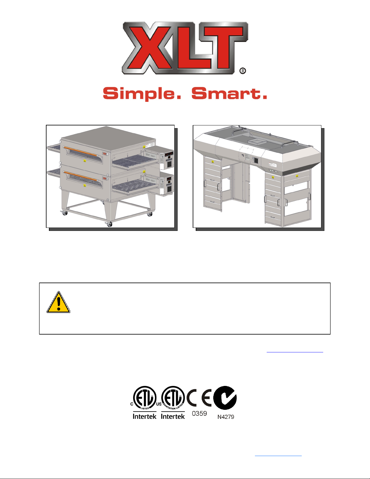
XD-9002B
GA-ASWD-HC
02/20/2013
XLT Oven & AVI Hood
Technical/Rough-In Specifications
for Gas & Electric Ovens & Hoods
This appliance is for professional use by qualified personnel. This appliance must be installed
by qualified persons in accordance with the regulations in force. This appliance must be installed with
sufficient ventilation to prevent the occurrence of unacceptable concentrations of substances harmful
to health in the room in which it is installed. This appliance needs an unobstructed flow of fresh air for
CAUTION
Electronic copies of the Installation & Operation Manual, Parts & Service Manual, Architectural
Drawings, & a list of International Authorized Distributors are available at: www.xltovens.com
For use with the following XLT Gas & Electric Oven Versions:
Australian (AE) D
Standard (S) D
World (W) D
satisfactory combustion & must be installed in a suitably ventilated room in accordance with current
regulations. This appliance should be serviced by qualified personnel at least every 12 months or
sooner if heavy use is expected.
For use with the following AVI Hood Versions:
Standard (S) C
World (W) C
2000887
XLT Ovens
PO Box 9090
Wichita, Kansas 67277
US: 888-443-2751 FAX: 316-943-2769 INTL: 316-943-2751 WEB: www.xltovens.com
Page 2
2
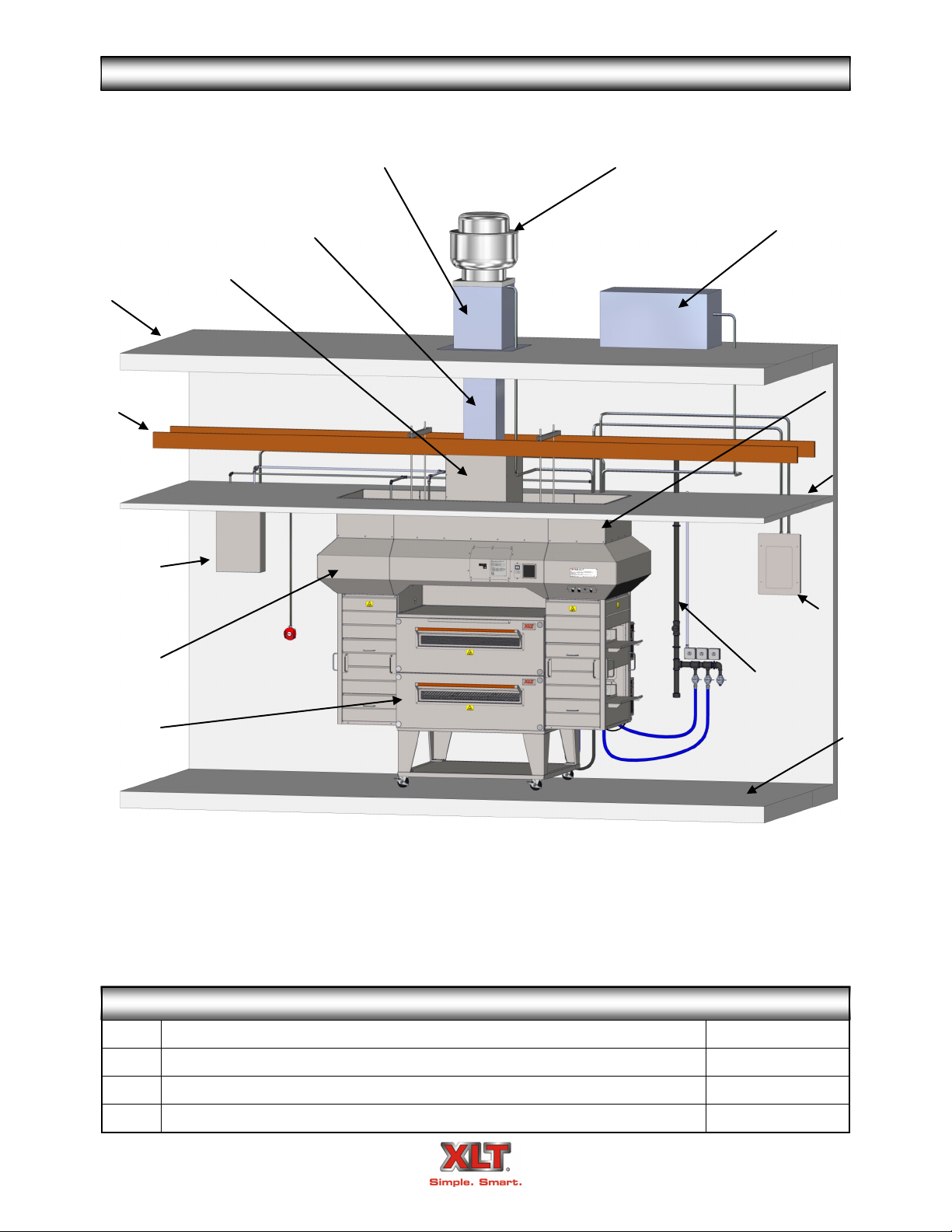
TYPICAL STORE INSTALLATION
Roof
Roof Joist
Fire
Suppression
Box
Duct Wrapper
Roof Curb
Welded Duct
Exhaust Fan
Roof Top Unit (RTU)
Valance
Ceiling
AVI Hood
XLT Oven
Typical Store Installation
Revision History Table
Revision Comments Date
A Initial Release 02/20/2013
Service Panel
Gas Service
Floor
Technical Support US: 888-443-2751 Technical Support INTL: 316-943-2751
Page 3

TABLE OF CONTENTS
Typical Store Installation ............................................................................................................. 2
Warning & Safety Information..................................................................................................... 4
Descriptions .................................................................................................................................. 5
Oven Electrical Requirements ...................................................................................................... 6
Hood Electrical Requirements...................................................................................................... 7
Gas Requirements......................................................................................................................... 8
Fire Suppression ......................................................................................................................... 10
Oven Dimensions ....................................................................................................................... 12
Hood Dimensions ....................................................................................................................... 14
Ventilation Requirements ........................................................................................................... 16
Pre-Installation Checklist ........................................................................................................... 17
Exhaust Fan Specifications ........................................................................................................ 17
This document is intended for use by general contractors, architects, sub-contractors and
store owners to provide information during the planning & pre-installation phases of installing
XLT Ovens & AVI Hoods. Please refer to the XLT Installation & Operation Manual for instructions on the assembly and utility hook-up phase of the project.
The process of getting a facility configured to owners’ expectations can be difficult and
frustrating, or it can be accomplished smoothly and on time. The information presented here can
help move the “D” portion of the image below towards “on time” and “under budget”.
3
The end goal is to obtain an occupancy permit from the Authority Having Jurisdiction
(AHJ). A thorough understanding of the prevailing local codes can expedite this process and prevent unexpected surprises. Proper planning and execution will allow the successful installation of
new ovens and hood in an existing store overnight with NO downtime.
The purpose of building codes is to provide minimum standards for the protection of life,
limb, property, environment, the safety and welfare of the consumer, general public, and the owners and occupants of structures regulated by codes. Building codes are constantly changing and
they can vary by state, county, city , town, and/or borough. While some states like California,
Florida, Massachusetts, Michigan, and New York have their own set of building codes, most states
have adopted the International Code Council (ICC) series of codes. Always check with your local
building code department in order to learn which codes are being used and how they will affect
you and your construction project. You may want to start by contacting your local inspection department, office of planning and zoning, and/or department of permits.
The information presented here has been proven to satisfy the latest code requirements.
Technical Support US: 888-443-2751 Technical Support INTL: 316-943-2751
Page 4
4
WARNING & SAFETY INFORMATION
The information contained in this manual should be distributed and read by all parties involved in procuring and installing this equipment prior to any work being performed.
To ensure an smooth installation the pre-installation checklist found in the back of this
manual must be reviewed before the XLT equipment is scheduled to arrive.
It is also advisable that a schedule be developed by the general contractor to ensure all activities are completed in the proper sequence and performed by the proper personnel.
XLT will assist in the coordination of disseminating information and scheduling the delivery of equipment. Please contact XLT or your distributor for additional assistance.
XLT wants you to be totally satisfied with every aspect of owning & using your oven &
hood. Your feedback, both positive & negative, is very important to us as it helps us understand
how to improve our products & our company. Our goal is to provide you, our customer, with
equipment that we can be proud to build & you can be proud to own.
To receive technical support for the oven or hood you purchased, contact XLT anytime day
or night, 365 days per year. Please be prepared to provide the Model & Serial Number.
Installation of all gas appliances & ventilation exhaust hoods should only be performed by a qualified professional who has read & understands these instructions &
is familiar with proper safety precautions. Read this manual thoroughly before in-
WARNING
All electrical connections must be made by a qualified electrician in accordance with NEC,
stalling or servicing this equipment.
OSHA, and all applicable national, state, and local codes.
All plumbing connections must be made by a qualified plumber in accordance with all applica-
ble national, state, and local codes.
All HVAC components must be made by a qualified mechanical contractor in accordance with
national, state, and local codes.
All ovens must have their own separate electrical circuit.
All systems in the AVI Hood must have their own separate electrical circuit.
Each XLT Oven must have it’s own gas shut-off valve.
XLT Ovens reserves the right to make changes in design & specifications, and/or make additions to or improvements to its product without imposing any obligations upon itself to install
them in products previously manufactured.
Technical Support US: 888-443-2751 Technical Support INTL: 316-943-2751
Page 5
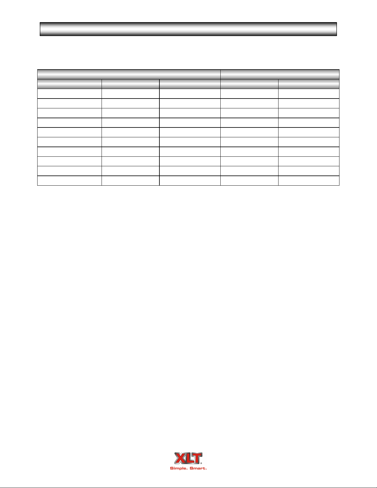
DESCRIPTIONS
Australia Standard World Standard World
XLT-1832D-AE XLT-1832D-S XLT-1832D-W AVI-1832C-S AVI-1832C-W
XLT-1855D-AE XLT-1855D-S XLT-1855D-W AVI-1855C-S AVI-1855C-W
XLT-2440D-AE XLT-2440D-S XLT-2440D-W AVI-2440C-S AVI-2440C-W
XLT-3240D-AE XLT-3240D-S XLT-3240D-W AVI-3240C-S AVI-3240C-W
XLT-3255D-AE XLT-3255D-S XLT-3255D-W AVI-3255C-S AVI-3255C-W
XLT-3270D-AE XLT-3270D-S XLT-3270D-W AVI-3270C-S AVI-3270C-W
XLT-3270D-2B-AE XLT-3270D-2B-S XLT-3270D-2B-W AVI-3270C-2B-S AVI-3270C-2B-W
XLT-3855D-AE XLT-3855D-S XLT-3855D-W AVI-3855C-S AVI-3855C-W
XLT-3870D-AE XLT-3870D-S XLT-3870D-W AVI-3870C-S AVI-3870C-W
XLT-3870D-2B-AE XLT-3870D-2B-S XLT-3870D-2B-W AVI-3870C-2B-S AVI-3870C-2B-W
Hoods
Ovens
This manual covers the following XLT GAS Oven & AVI Hood models:
The first 2 digits of the model number represent the conveyor width & the last two digits
indicate the bake chamber length. The ovens may be used as a single, double, or triple oven stack
configuration. All ovens are available in (NAT) Natural Gas or (LP) Liquid Petroleum gas.
(Electric ovens are also available). The 3270-2B & 3870-2B models have two burners, one on
each side, & have two control boxes. All other models have only a single burner with a single
control box that can be supplied on either end. All models can be configured for a split belt conveyor.
5
All installations must conform to local building & mechanical codes.
Utilities must be easily accessible when the ovens are in the installed position. Do not in-
stall utilities directly behind the ovens.
In Australia follow AS/NZS 3000 Wiring and AS5601 Gas Installation.
Additional restrictions apply. Please see the XLT Installation & Operation Manual for more details.
CERTIFICATIONS
For a complete list of Certifications, please see the XLT Installation & Operation Manual.
Technical Support US: 888-443-2751 Technical Support INTL: 316-943-2751
Page 6
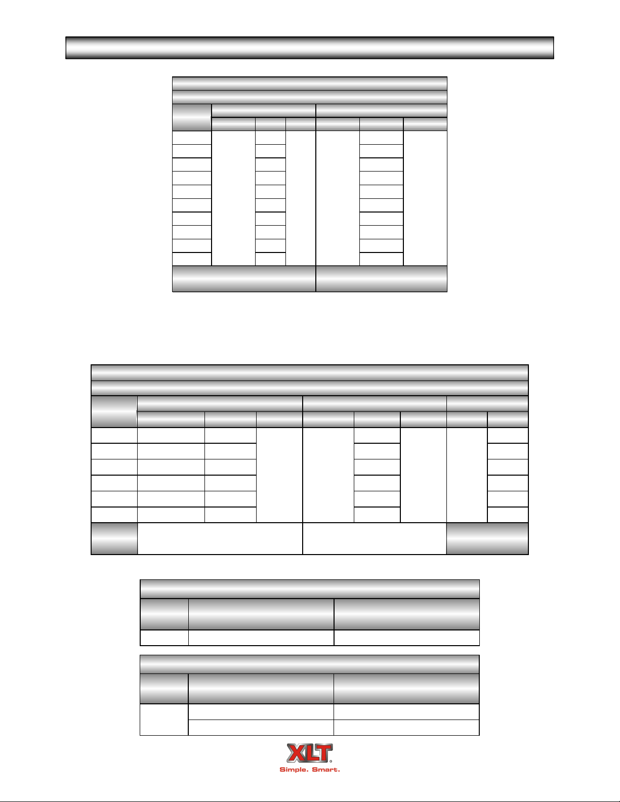
6
Volts AC Amps Hertz Volts AC Amps Hertz
1832 6 3
1855 6 3
2440 6 3
3240 6 3
3255 6 3
3270
6 3
3270-2B
12 6
3855 6 3
3870 6 3
3870-2B 12 6
Install in accordance with AS/NZS
3000 Wiring
50
Gas Oven Electrical Require ments
Per EACH Oven
Oven
Model
AUSTRALIA & WORLD
STANDARD
120 VAC
1Φ
60
220/230/
240 VAC
1Φ
Volts AC Amps Hertz Volts AC Amps Hertz Phase KW
1832 208/240 44/38 24 16
1855 208/240/480 88/77/38 48 32
2440 208/240/480 75/65/33 41 27
3240 208/240/480 75/65/33 41 27
3255 208/240/480 88/77/38 48 32
3855 208/240/480 88/77/38 48 32
Electric Oven Electrical Requirements
Per EACH Oven
Oven
Model
STANDARD
WORLD
ALL
60
380503
4 Wire Service - L1, L2, L3
5 Wire Service - L1, L2, L3
N +2 Grounds (per oven)
+1 Ground (per oven)
All
Conveyor Belt Times
Oven
Models
MINIMUM
MAXIMUM
1:30
17:00
Oven Operating Temperature Range
Oven
Models
MINIMUM
MAXIMUM
400° F
590° F
All
205° C
310° C
OVEN ELECTRICAL REQUIREMENTS
FOR EACH GAS OVEN:
A separate 20 amp circuit breaker must be provided for each oven deck.
Electrical connections must be accessible when the ovens are in the installed position.
Electrical connections must meet all local code requirements.
A DISCONNECT MUST BE INSTALLED IN ACCORDANCE TO LOCAL BUILDING CODES:
Technical Support US: 888-443-2751 Technical Support INTL: 316-943-2751
Page 7
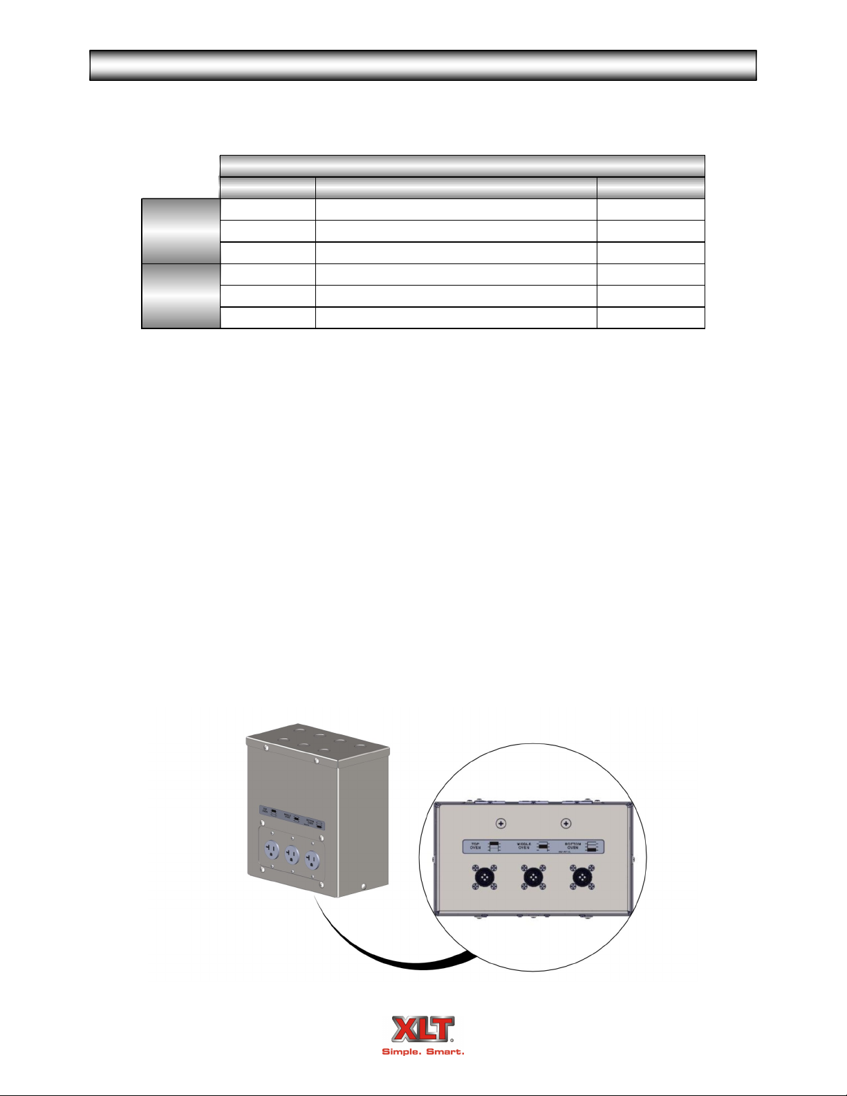
# of Circuits Rating Purpose
1 208/240 VAC, 1 Phase, 60 Hz, 6 Amp VFD Controller
up to 3 120 VAC, 1 Phase, 60 Hz, 20 Amp Ovens
1 120 VAC, 1 Phase, 60 Hz, 1 Amp System Power
1 230 VAC, 1 Phase, 50 Hz, 6 Amp VFD Controller
up to 3 230 VAC, 1 Phase, 50 Hz, 10 Amp Ovens
1 230 VAC, 1 Phase, 50 Hz, 1 Amp System Power
Standard
World
AVI Hood Electric Utility Specifications
HOOD ELECTRICAL REQUIREMENTS
Inputs into VFD Box
Outputs from Junction Box
The AVI Hood system provides:
Three (3) switching outputs for HVAC dampers and dedicated units
One (1) 230 VAC, 10 Amp, variable frequency, three phase power output for the ventilation
exhaust fan.
Up to Three (3) receptacles for ovens.
One (1) 120 VAC fire alarm signal for Standard hoods, or one (1) 24 VAC fire alarm signal for
World Hoods
7
For Oven & Hood installations with the VFD option, all electrical connections are made in
the junction box located on the right rear corner of the upper portion of the hood. Power for the
exhaust fan is provided from the VFD controller. Optional fire suppression & MUA damper relay
connections may also be made in the junction box.
For Oven & Hood installations without the VFD option only the lighting and oven receptacle connections are made in the junction box. Ovens without a AVI hood are plugged into the receptacles on the wall.
Technical Support US: 888-443-2751 Technical Support INTL: 316-943-2751
Page 8
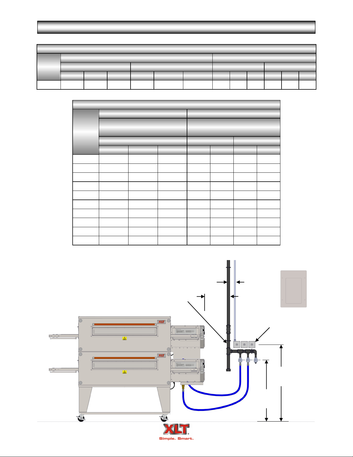
8
W/C mbar kPa W/C mbar kPa W/C mbar kPa W/C mbar kPa
All 6-14 15-35 1.5-3.5 11.5-14 27.5-35.0 2.75-3.50 3.5 8.75 0.875 10 25 2.5
Natural Gas
LP Gas
Natural Gas
LP Gas
Ove n
Models
Gas Oven Fuel Pressure Requirements
Inlet Pressure Range
Manifold Pressure
BTU/HR KW/HR MJ/HR Inches MM Inches MM
1832 47,700 13.97 50.32 0.125 3.18 0.081 2.06
1855 76,500 22.42 80.71 0.156 3.96 0.096 2.44
2440 67,200 19.69 70.89 0.144 3.66 0.089 2.26
3240 96,100 28.14 101.39 0.170 4.31 0.111 2.82
3255 119,900 35.11 126.5 0.191 4.82 0.116 2.95
3270 150,000 43.96 158.25 0.221 5.61 0.136 3.45
3270-2B 140,800 41.23 148.55 0.144 3.66 0.096 2.44
3855 142,200 41.64 150.02 0.209 5.31 0.125 3.18
3870 150,000 43.69 158.25 0.221 5.61 0.136 3.45
3870-2B 137,900 40.38 145.49 0.144 3.66 0.096 2.44
Gas Oven Heating Values & Orifice Sizes
NATLPAll Fuels
Standard, World & Australia
Standard, World & Australia
Oven
Model
Heating Values
Orifice Sizes
GAS REQUIREMENTS
Utilities must be easily accessible when the ovens
are in the installed position. Do not install utilities behind the ovens.
Gas Manifold
6.00
[152]
3.00
[76]
Technical Support US: 888-443-2751 Technical Support INTL: 316-943-2751
Electrical Supply
48.00
[1219]
42.00
[1067]
Page 9
GAS REQUIREMENTS
The gas supply should have a gas meter & regulator large enough to handle all of the gas
appliances, such as the furnace, water heater, & ovens, in operation at the same time. Add up all
of the BTU / kw / MJ ratings to determine the total load. Gas hose assemblies with quick disconnects for each oven deck will be installed at each valve during oven installation when purchased.
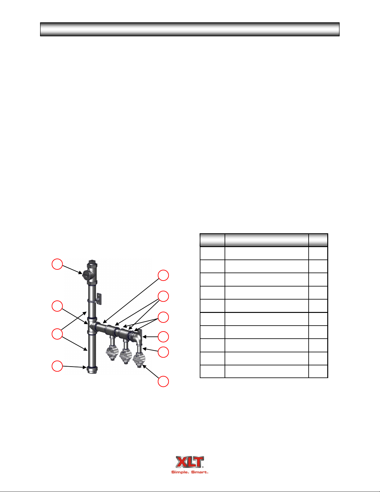
GAS MANIFOLD WITH SEDIMENT TRAP
A sediment trap must be installed by the owner and/or General Contractor as close as practical to the inlet of the oven at the time of installation. This requirement is in keeping with ANSI
Z223.1-2012/NFPA 54-2012, section 9.6.7. The design shown below will effectively keep all contaminates from getting into the gas valves in the ovens. The cost to construct the gas manifold is
extremely inexpensive compared to the costs associated with oven failure, such as downtime, replacement parts, and service call labor. Failure to install a sediment trap will void the product warranty. The Gas Supply manifold is available from XLT upon request.
A minimum of a 1 1/2 supply line is required.
9
Item # Description Qty
1 ¾ Manual Gas Valve 3
2
7
2 1-½ Ball Valve 1
3 ¾ x 3 Nipple 3
4 1-½ Pipe Cap 1
9
8
5
4
6
10
3
5 1-½ x 10 Nipple 2
6 1-½ x 3 Nipple 2
7 1-½ x 5 Nipple 1
8 1-½ Tee 1
9 1-½ x ¾ x 1-½ Reducing Tee 2
10 1-½ x ¾ Reducing Elbow 1
1
Do not use Teflon tape on gas line connections as this can possibly cause gas valve mal-
function or plugging of orifices from shreds of tape. Use of Teflon tape WILL VOID
warranty.
Technical Support US: 888-443-2751 Technical Support INTL: 316-943-2751
Page 10
10
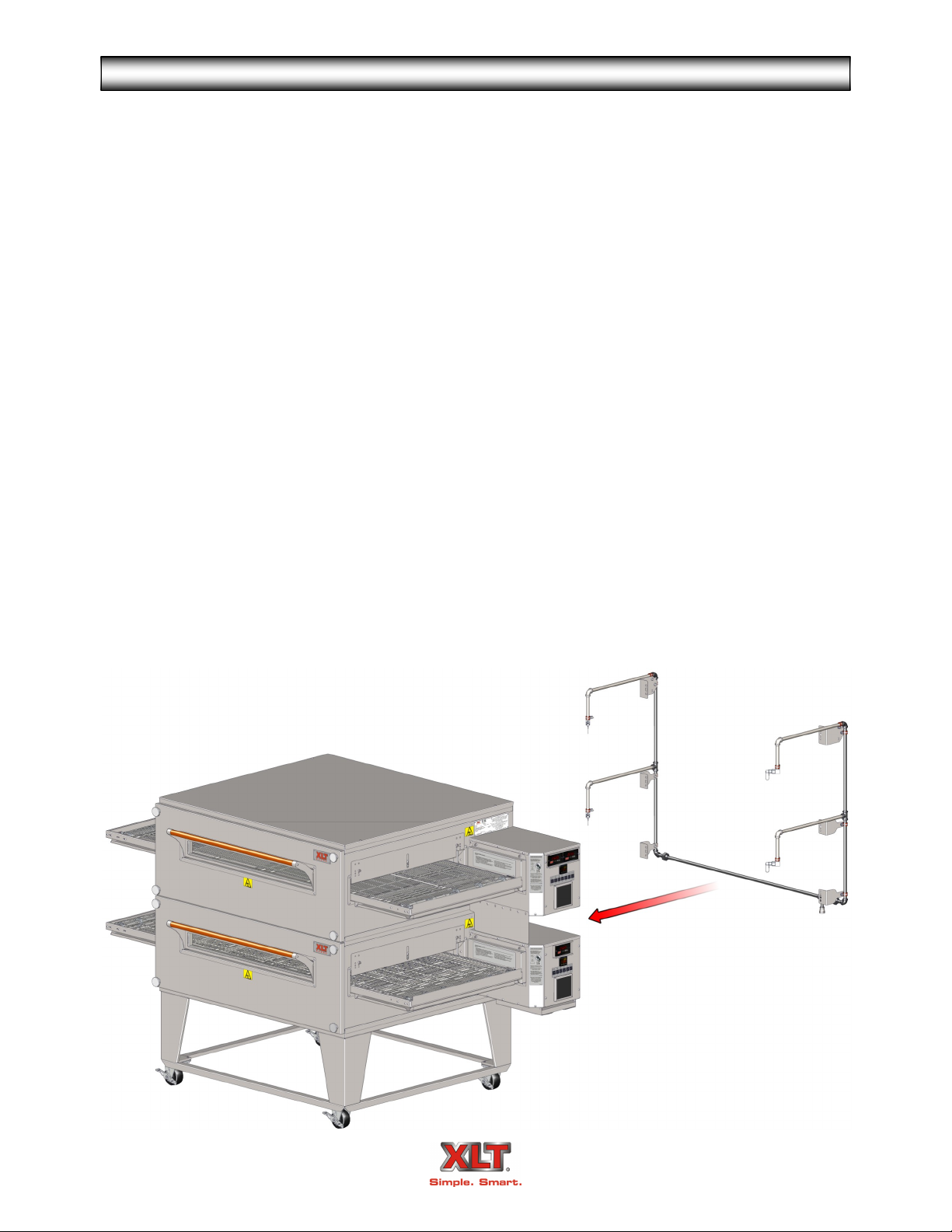
In the event you are required to install fire suppression, XLT offers an accessory kit for ovens, and also fire suppression piping for the AVI hood as an option. The Engineers at XLT have
designed the fire suppression system for XLT ovens and AVI hoods to meet ICC and NFPA codes.
Field installations can be more expensive, less effective, and can interfere with daily operations
and maintenance.
A fire suppression system consists of five (5) main components:
Manual Pull Station
Main Cabinet that houses the tank and valve
Mechanical Gas Valve
Oven Piping & Nozzles
Hood Piping & Nozzles
All of these elements need to be interconnected mechanically with wire rope cables, and a
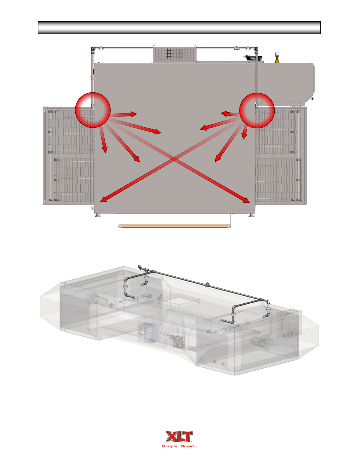
piping system must connect the tank with fire agent to the nozzles in both the oven and hood.
The fire suppression system can be activated by either manually pulling down on the handle, or whenever the temperature rises high enough to melt a link in the hood. When the link melts
or the handle is pulled, spring tension opens the valve which releases the agent contained in the
tank and then sprays through nozzles mounted in both the oven and hood.
FIRE SUPPRESSION
EXPLODED VIEW OF OVEN FIRE SUPPRESSION
Technical Support US: 888-443-2751 Technical Support INTL: 316-943-2751
Page 11
FIRE SUPPRESSION
11
TRANSPARENT VIEW OF HOOD FIRE SUPPRESSION
Technical Support US: 888-443-2751 Technical Support INTL: 316-943-2751
Page 12
12
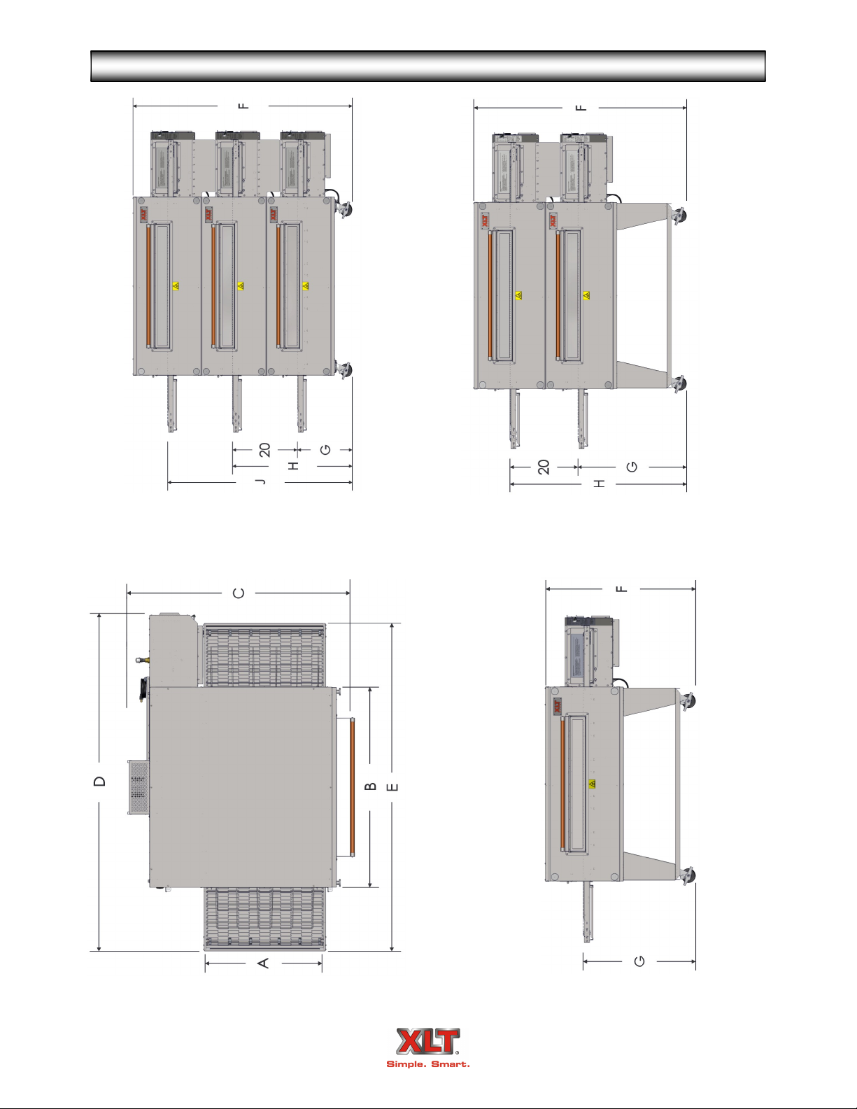
OVEN DIMENSIONS
Technical Support US: 888-443-2751 Technical Support INTL: 316-943-2751
Page 13
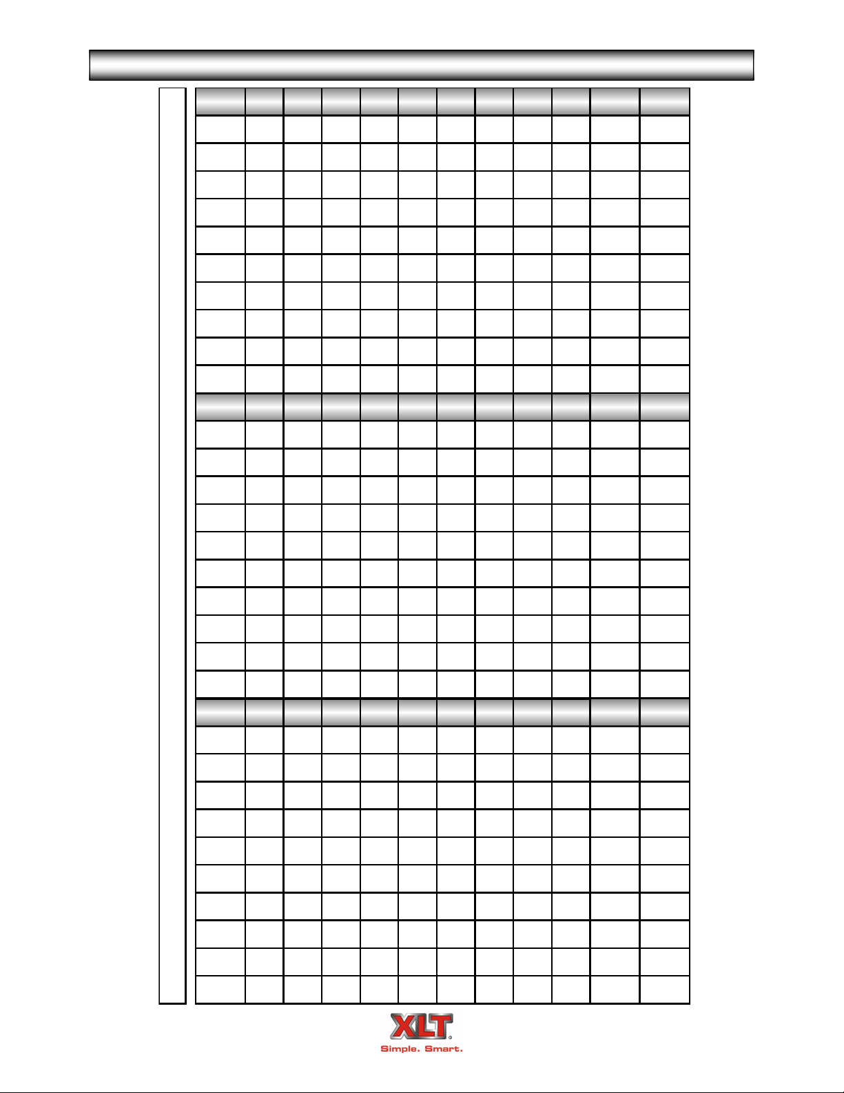
OVEN DIMENSIONS
18 32 48 3/8 70 1/4 67 1/4 42 3/4 32
477 612
[457] [813] [1229] [1784] [1708] [1086] [813] [216] [278]
18 55 48 3/8 93 1/4 90 1/4 42 3/4 32
624 802
[457] [1397] [1229] [2369] [2292] [1086] [813] [283] [364]
24 40 54 3/8 78 1/4 75 1/4 42 3/4 32
543 698
[610] [1016] [1381] [1988] [1911] [1086] [813] [246] [317]
32 40 62 3/8 78 1/4 75 1/4 42 3/4 32
629 787
[813] [1016] [1584] [1988] [1911] [1086] [813] [285] [357]
32 55 62 3/8 93 1/4 90 1/4 42 3/4 32
757 935
[813] [1397] [1584] [2369] [2292] [1086] [813] [343] [424]
32 70 62 3/8 108 1/4 105 1/4 42 3/4 32
879 1071
[813] [1778] [1584] [2750] [2673] [1086] [813] [399] [486]
32 70 62 3/8 111 105 1/4 42 3/4 32
985 1168
[813] [1778] [1584] [2819] [2673] [1086] [813] [447] [530]
38 55 68 3/8 93 1/4 90 1/4 42 3/4 32
829 1012
[965] [1397] [1737] [2369] [2292] [1086] [813] [376] [459]
38 70 68 3/8 108 1/4 105 1/4 42 3/4 32
956 1139
[965] [1778] [1737] [2750] [2673] [1086] [813] [434] [517]
38 70 68 3/8 111 105 1/4 42 3/4 32
1077 1274
[965] [1778] [1737] [2819] [2673] [1086] [813] [489] [578]
18 32 48 3/8 70 1/4 67 1/4 62 3/4 32 52
863 1133
[457] [813] [1229] [1784] [1708] [1594] [813] [1321] [391] [514]
18 55 48 3/8 93 1/4 90 1/4 62 3/4 32 52
1141 1497
[457] [1397] [1229] [2369] [2292] [1594] [813] [1321] [518] [679]
24 40 54 3/8 78 1/4 75 1/4 62 3/4 32 52
981 1291
[610] [1016] [1381] [1988] [1911] [1594] [813] [1321] [445] [586]
32 40 62 3/8 78 1/4 75 1/4 62 3/4 32 52
1142 1458
[813] [1016] [1584] [1988] [1911] [1594] [813] [1321] [518] [661]
32 55 62 3/8 93 1/4 90 1/4 62 3/4 32 52
1380 1736
[813] [1397] [1584] [2369] [2292] [1594] [813] [1321] [626] [787]
32 70 62 3/8 108 1/4 105 1/4 62 3/4 32 52
1605 1961
[813] [1778] [1584] [2750] [2673] [1594] [813] [1321] [728] [889]
32 70 62 3/8 111 105 1/4 62 3/4 32 52
1817 2201
[813] [1778] [1584] [2819] [2673] [1594] [813] [1321] [824] [998]
38 55 68 3/8 93 1/4 90 1/4 62 3/4 32 52
1513 1879
[965] [1397] [1737] [2369] [2292] [1594] [813] [1321] [686] [852]
38 70 68 3/8 108 1/4 105 1/4 62 3/4 32 52
1742 2108
[965] [1778] [1737] [2750] [2673] [1594] [813] [1321] [790] [956]
38 70 68 3/8 111 105 1/4 62 3/4 32 52
1984 2378
[965] [1778] [1737] [2819] [2673] [1594] [813] [1321] [900] [1079]
18 32 48 3/8 70 1/4 67 1/4 67 3/4 17 37 57
1216 1621
[457] [813] [1229] [1784] [1708] [1721] [432] [940] [1448] [552] [735]
18 55 48 3/8 93 1/4 90 1/4 67 3/4 17 37 57
1624 2158
[457] [1397] [1229] [2369] [2292] [1721] [432] [940] [1448] [737] [979]
24 40 54 3/8 78 1/4 75 1/4 67 3/4 17 37 57
1386 1851
[610] [1016] [1381] [1988] [1911] [1721] [432] [940] [1448] [629] [840]
32 40 62 3/8 78 1/4 75 1/4 67 3/4 17 37 57
1617 2091
[813] [1016] [1584] [1988] [1911] [1721] [432] [940] [1448] [733] [948]
32 55 62 3/8 93 1/4 90 1/4 67 3/4 17 37 57
1964 2498
[813] [1397] [1584] [2369] [2292] [1721] [433] [941] [1448] [891] [1133]
32 70 62 3/8 108 1/4 105 1/4 67 3/4 17 37 57
2292 2826
[813] [1778] [1584] [2750] [2673] [1721] [433] [941] [1448] [1040] [1282]
32 70 62 3/8 111 105 1/4 67 3/4 17 37 57
2610 3186
[813] [1778] [1584] [2819] [2673] [1721] [433] [941] [1448] [1184] [1445]
38 55 68 3/8 93 1/4 90 1/4 67 3/4 17 37 57
2156 2705
[965] [1397] [1737] [2369] [2292] [1721] [433] [941] [1448] [978] [1227]
38 70 68 3/8 108 1/4 105 1/4 67 3/4 17 37 57
2483 3032
[965] [1778] [1737] [2750] [2673] [1721] [433] [941] [1448] [1126] [1375]
38 70 68 3/8 111 105 1/4 67 3/4 17 37 57
2846 3437
[965] [1778] [1737] [2819] [2673] [1721] [433] [941] [1448] [1291] [1559]
3870
NOTE: All dimensions in inch es [millimeters], ± 1/4 [6], unless otherwise no ted. All weig hts in pou nds [kilog rams] unless otherwise noted.
3270
N/A
3870
N/A
3270ABCD
2440
N/A
N/A
3240
N/A
CRATED
WEIGHT
CRATED
WEIGHT
CRATED
WEIGHT
OVEN
WEIGHT
1832
N/A
N/A
1855
N/A
N/A
EFGHJ
SINGLE
OVEN
N/A
3270
N/A
N/A
3870-2B
N/A
N/A
3270-2B
N/A
N/A
3870
N/A
N/A
OVEN
WEIGHT
1832
N/A
1855
N/A
EFGHJ
DOUBLE
STACK
ABC
D
2440
N/A
3240
N/A
3255
N/A
N/A
TRIPLE
STACK
ABCDEFGHJ
1832
1855
2440
3240
3870-2B
3255
3870-2B
3255
N/A
N/A
3855
N/A
N/A
3270-2B
N/A
3855
N/A
3270-2B
3855
OVEN
WEIGHT
13
Technical Support US: 888-443-2751 Technical Support INTL: 316-943-2751
Page 14
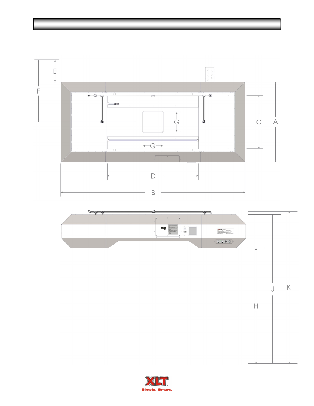
14
HOOD DIMENSIONS
ALL DIMENSIONS ARE FROM FINISHED FLOOR
Technical Support US: 888-443-2751 Technical Support INTL: 316-943-2751
Page 15
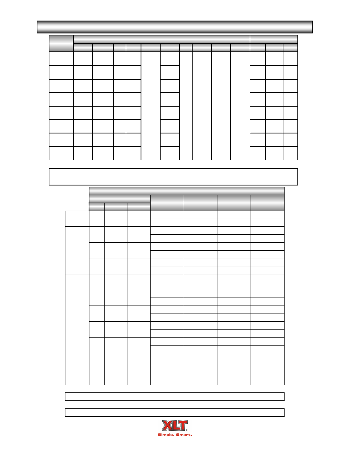
HOOD DIMENSIONS
A B C D E F G H J K Single Double Triple
34 3/8 88 5/8 18 32 30 5/8 540 500 525
[873] [2251] [457] [813] [778]
[245] [227] [238]
34 3/8 88 5/8 18 55 30 5/8
620 560 585
[873] 111.375 [457] [1397] [778]
[281] [254] [265]
40 3/8 96 5/8 24 40 33 5/8 620 570 595
[1026] [2454] [610] [1016] [854]
[281] [259] [270]
48 3/8 96 5/8 32 40 37 5/8 680 630 655
[1229] [2454] [813] [1016] [956]
[308] [286] [297]
48 3/8 111 5/8 32 55 37 5/8 740 670 695
[1229] [2835] [813] [1397] [956]
[336] [304] [315]
48 3/8 126 5/8 32 70 37 5/8
780 705 720
[1229] [3216] [813] [1778] [956]
[354] [320] [327]
54 3/8 111 5/8 38 55 40 5/8 795 720 745
[1381] [2835] [965] [1397] [1032]
[361] [327] [338]
54 3/8 126 5/8 38 70 40 5/8
825 750 770
[1381] [3216] [965] [1778] [1032]
[374] [340] [349]
Hood Dimensions
13 1/2
[343]
12
[305]
1855
NOTE: All dimens ions in inches [millimeters], ± 1/4 [6], unless otherwise noted.
All weights in pounds [kilograms] unless otherwise noted.
Hood Weights
69 5/8
89 7/8
91 3/4
[1768]
[2283]
[2330]
3870
3870-2B
Oven
Model
1832
2440
3240
3255
3270
3270-2B
3855
Top Middle Bottom
500 500 500 500
[14.16] [14.16] [14.16] [14.16]
500 500 500 500
[14.16] [14.16] [14.16] [14.16]
506 644 828 966
[14.33] [18.24] [23.45] [27.35]
506 644 828 966
[14.33] [18.24] [23.45] [27.35]
500 500 500 500
[14.16] [14.16] [14.16] [14.16]
506 644 828 966
[14.33] [18.24] [23.45] [27.35]
766 975 1254 1463
[21.69] [27.61] [35.51] [41.43]
506 644 828 966
[14.33] [18.24] [23.45] [27.35]
766 975 1254 1463
[21.69] [27.61] [35.51] [41.43]
766 975 1254 1463
[21.69] [27.61] [35.51] [41.43]
766 975 1254 1463
[21.69] [27.61] [35.51] [41.43]
Exhaust Flow Rates VOLUME (min. recommended)
Switches On
18xx
32xx
38xx
24xx
Double
Triple
X
Single
X
X
XXXXXXXXXXX
XXX
NOTE: All values are CFM [M3/Min] unless otherwise noted.
NOTE: Figures represent TOTAL VOLUME measured at the duct.
15
Technical Support US: 888-443-2751 Technical Support INTL: 316-943-2751
Page 16

16
VENTILATION REQUIREMENTS
Ventilation Requirements
A powered ventilation hood is required to remove heat and vapors. Some provision must
be made to replenish the amount of air that is extracted from the building. The hood and HVAC
installation must meet local building and mechanical codes. Requirements vary throughout the
country depending upon location. Proper ventilation is the oven owner’s responsibility. The AVI
Hood system is designed to meet all requirements for XLT ovens and it is our recommendation
that this system be used.
Ventilation Guidelines
Obtain information from the authority having jurisdiction to determine the requirements for
your installation. Your ventilation hood supplier and HVAC contractor should be contacted to
provide guidance. An air balance test is highly recommended, performed by a licensed contractor.
A properly engineered and installed ventilation hood and HVAC system will expedite approval,
reduce all maintenance costs, and provide a more comfortable working environment. XLT also
recommends that the operator switches for the ovens and the operator switch for the exhaust fan be
interlocked so that the exhaust fan gets energized whenever the ovens are turned on. For more information, see the following links at xltovens.com:
Kitchen Ventilation Design Guide 1
Kitchen Ventilation Design Guide 2
Kitchen Ventilation Design Guide 3
Kitchen Ventilation Design Guide 4
Ventilation Performance Test
After the oven and ventilation hood have been installed and are operating, a smoke candle
can be used to “see” if the heat and vapors are being completely extracted. The test procedure is
outlined below:
The oven must be operating at 450º-500ºF / 232º-260ºC.
The conveyor must be turned off.
The ventilation hood exhaust fan must be turned on.
Put a smoke candle in a pan on the conveyor belt at the center of the oven.
Observe the smoke pattern coming out of the oven.
Repeat the smoke candle test for each oven, as well as when all ovens are operating.
The ventilation hood must capture all of the smoke from the oven.
After the exhaust fan has been adjusted to completely capture and contain the heat, there
needs to be a corresponding amount of make up air (MUA) introduced into the building to offset
the amount of air volume being removed. An air balance test can determine the proper amount of
make-up air flow rates.
Technical Support US: 888-443-2751 Technical Support INTL: 316-943-2751
Page 17

PRE-INSTALLATION CHECKLIST
17
There are many things that will help with the installation of XLT equipment, and make for a
smooth installation. The following list outlines the tasks necessary for successful installation of
ovens and/or hoods, whether the installation occurs in a new store or for the remodel of an existing
store. This list is to be used as a checklist to verify all aspects of XLT equipment is installed properly. If any additional information is required please refer to the I&O Manual. Manuals can be
found at xltovens.com:
Yes No
Yes No
Yes No
Yes No
Yes No
Yes No
Yes No
Yes No
Yes No
Yes No
Yes No
Yes No
Yes No
Gas Requirements:
Install adequate size gas lines (2” preferred 1 1/2” minimum)
Install shutoff gas valve for each oven
Install gas meter & regulator (Individual regulator for each oven is pre-
ferred)
Verify adequate gas pressure for all equipment in store (Minimum 6”
W.C. supplied to ovens with all other equipment running at full load)
Sediment trap must be installed, refer to local code for proper require-
ments
Electrical Requirements:
Dedicated 20 Amp breaker installed for each oven
All applicable dedicated circuits are installed for the AVI
All circuits are the correct Phase for each piece of equipment
Hood Requirements: (If Applicable)
Proper ceiling support is in place for hood installation
Proper ceiling clearance for the AVI
Install Roof Curb
Install Exhaust Fan (Adequate Fan for installation)
Install Duct
Technical Support US: 888-443-2751 Technical Support INTL: 316-943-2751
Page 18
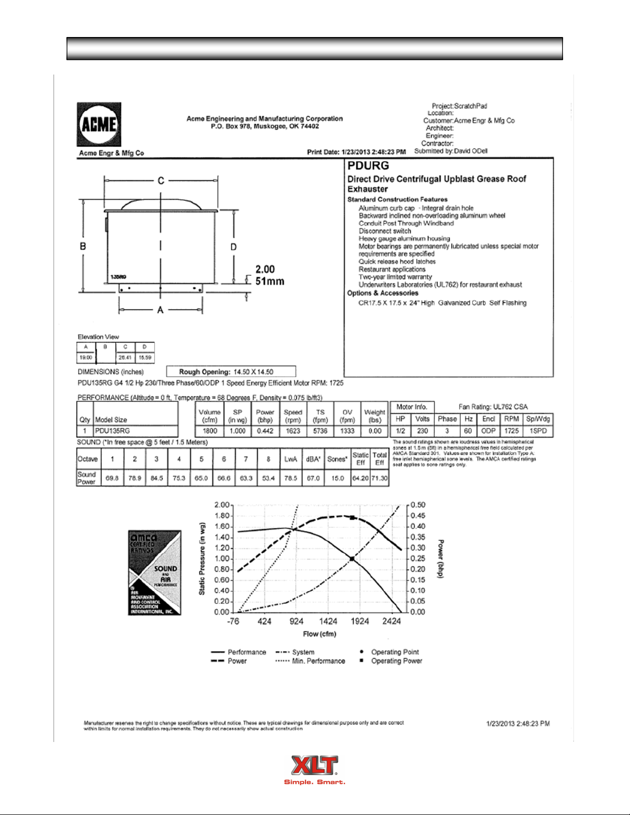
18
EXHAUST FAN SPECIFICATIONS
Technical Support US: 888-443-2751 Technical Support INTL: 316-943-2751
Page 19
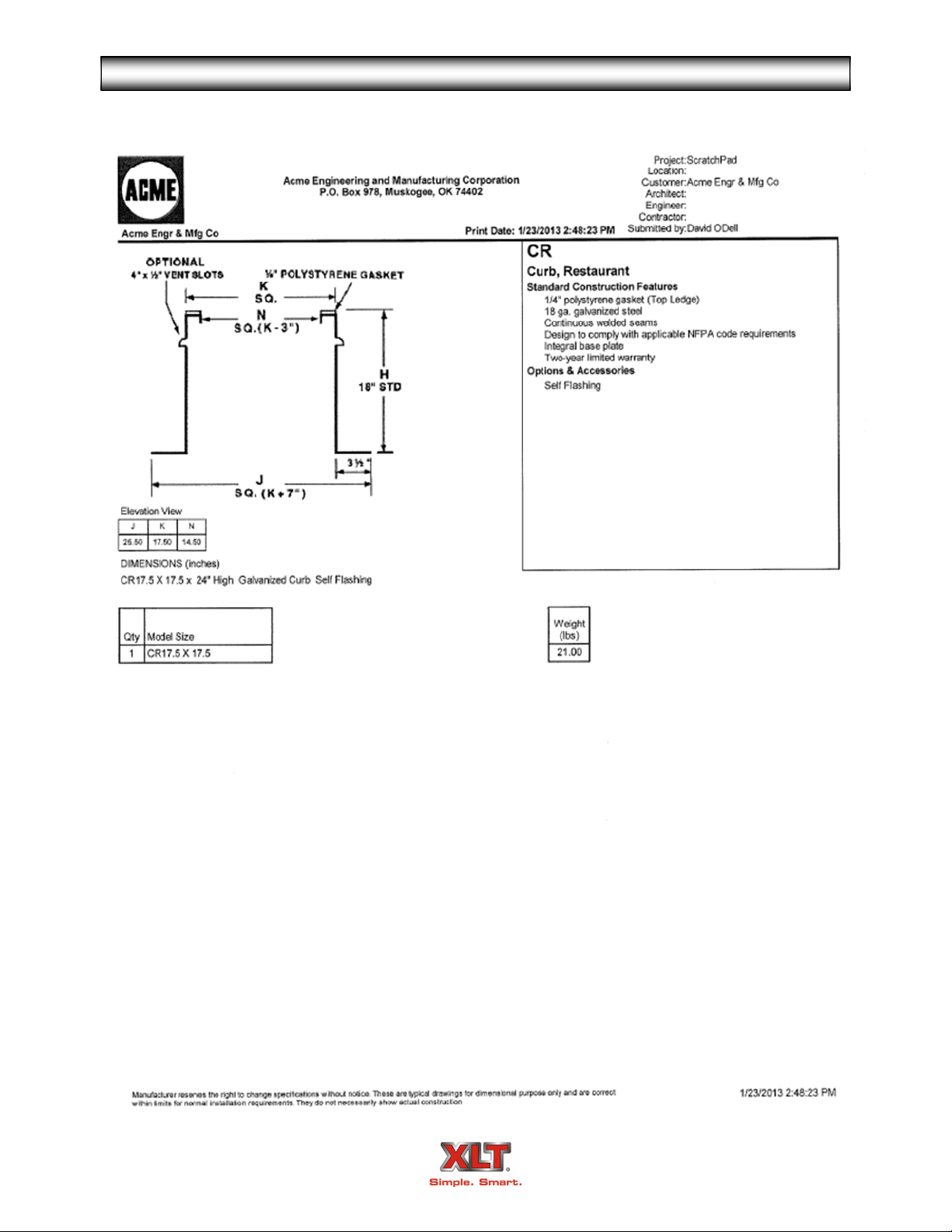
EXHAUST FAN SPECIFICATIONS
19
Technical Support US: 888-443-2751 Technical Support INTL: 316-943-2751
Page 20

XLT Ovens
PO Box 9090
Wichita, Kansas 67277
US: 888-443-2751 FAX: 316-943-2769 INTL: 316-943-2751 WEB: www.xltovens.com
 Loading...