


USER MANUAL NS6/NS12P/NS12PF
USER MANUAL
XLNT
DataMotion
NS6
NS12P
NS12PF
ETHERNET SWITCHES

3
USER MANUAL NS6/NS12P/NS12PF
Declaration of Conformity
Manufacturer's name:
XLNT Advanced Technologies
Address:
Proostwetering 50
35432 AH Utrecht
The Netherlands
Declares that the product:
Name: NS6 Ethernet switch
Conforms to the following EEC Directives
89/336/EEC Electromechanical Contamination Directive
2006/95/EEC Low Voltage Directive
IEC 60950-1:2005, mod: Safety of Information Technology Equipment,
including Electrical Business Equipment
EN55022 (1998) +A1(2000) +A2(2003): Information technology equipment. Radio disturbance characteristics.
EN 55024 (1998) +A1 (2000) +A2(2003): Information technology equipment. Immunity characteristics.
Utrecht, August 8th, 2007
XLNT Advanced Technologies
Declaration of Conformity

4
USER MANUAL NS6/NS12P/NS12PF
Declaration of Conformity
Declaration of Conformity
Manufacturer's name:
XLNT Advanced Technologies
Address:
Zonnebaan 42
3542 EG Utrecht
The Netherlands
Declares that the products:
Name: NS12P Ethernet switch
Name: NS12PF Ethernet switch
Conform to the following EEC Directives
89/336/EEC Electromechanical Contamination Directive
2006/95/EEC Low Voltage Directive
IEC 60950-1:2005, mod: Safety of Information Technology Equipment,
including Electrical Business Equipment
EN55022 (1998) +A1(2000) +A2(2003): Information technology equipment. Radio disturbance characteristics.
EN61000-3-2 (2000): Limits for harmonic current emissions
EN61000-3-3 (1995) +A1(2001): Limitation of voltage fluctuations and
flicker in low-voltage supply systems
EN 55024 (1998) +A1 (2000) +A2(2003): Information technology equipment. Immunity characteristics.
Utrecht, August 8th, 2007
XLNT Advanced Technologies

5
USER MANUAL NS6/NS12P/NS12PF
Important Safety Instructions
It is extremely important to read ALL safety information and instructions provided in this manual and any accompanying documentation before installing and operating the products described
herein.
Heed all cautions and warnings during installation and use of this
product.
Keep this instruction manual for future reference
This unit does not contain any user serviceable parts.
Do not open this unit. Doing so will void warranty and might present a risk. Servicing must be performed by qualified personnel
only. Servicing is required when the apparatus has been damaged
in any way, such as power-supply cord or plug being damaged,
liquid has been spilled or objects have fallen into the apparatus,
the apparatus has been exposed to rain or moisture, does not
operate normally, or has been dropped.
This unit is designed for indoor use. Do not use this unit in a wet
or damp environment or near to water.
Do not install near any heat sources such as radiators, heat
registers, stoves, or other apparatus (including amplifiers) that
produce heat.
This unit is not designed for residential use.
Do not block any ventilation openings. Install in accordance with
the manufacturer’s instructions.
Do not defeat the safety purpose of the polarized or groundingtype plug. If the provided plug does not fit into your outlet, consult
an electrician for replacement of the obsolete connector.
Important safety instructions

6
USER MANUAL NS6/NS12P/NS12PF
Do not connect or disconnect the PowerCon® connector under load.
Protect the power lead from being walked on or pinched particularly
at plugs, convenience receptacles, and the point where they exit from
the apparatus. When damaged, replace the power lead.
Unplug this apparatus during lightning storms or when unused for
long periods of time.
The NS12PF Ethernet switch contains two Class 1 laser devices. When
unconnected, the covers in the connector should block light emitted
by these devices. However, as additional safety measure, do not look
directly into this connector at any time.
The used laser-based transceivers are classified as AEL Class I (U.S.
21 CFR(J) and AEL Class 1 per EN 60825-1 (+A11). They are eye safe
under normal operating conditions and under all reasonably forseeable single fault conditions per EN60825-1. TUV Rheinland has
granted certification to these transceivers for laser eye safety and
use in EN 60950 and EN 60825-2 applications.
Disclaimer
All rights reserved. Although the information in this manual has been
compiled with care, individual items may vary in size, ratings and
functionality from what is included in this manual.
XLNT disclaims any liability for damage, losses or other consequences suffered or incurred in connection with the use of the measurements, data or information contained in this manual. XLNT may
change this product without prior notice.
EtherCon®, OpticalCon® and PowerCon® are trademarks of Neutrik®
A.G.
Important safety instructions

7
USER MANUAL NS6/NS12P/NS12PF
Contents
Contents
Declaration of Conformity...................................................................
Declaration of Conformity...................................................................
Important Safety Instructions.............................................................
Disclaimer...........................................................................................
Table of Contents................................................................................
About this Manual...............................................................................
Additional resources...........................................................................
Customer Service and Warranty.........................................................
Recycling and hazardous substances...............................................
Chapter 1: Description.......................................................................
Application...........................................................................................
Features..............................................................................................
Products..............................................................................................
Power over Ethernet............................................................................
Copper Ethernet cabling.....................................................................
Fiberoptic Ethernet Cabling................................................................
Chapter 2: Using the NS6...................................................................
Included Items....................................................................................
Front Panel layout...............................................................................
Installation requirements...................................................................
Connecting Ethernet...........................................................................
Power Requirements..........................................................................
LED-signals.........................................................................................
Chapter 3: Using the NS12P..............................................................
Included Items....................................................................................
Front Panel layout...............................................................................
Rear Panel layout................................................................................
Installation requirements...................................................................
Connecting Ethernet...........................................................................
Power Requirements..........................................................................
LED-signals.........................................................................................
3
4
5
6
7
9
9
9
9
10
10
10
11
13
14
14
15
15
15
16
17
17
17
19
19
19
20
20
21
21
21

8
USER MANUAL NS6/NS12P/NS12PF
Chapter 4: Using the NS12PF............................................................
Included Items....................................................................................
Front Panel layout...............................................................................
Rear Panel layout................................................................................
Installation requirements...................................................................
Connecting Ethernet...........................................................................
Power Requirements..........................................................................
LED-signals.........................................................................................
Chapter 5: Troubleshooting..............................................................
Power..................................................................................................
Data.....................................................................................................
Hardware Failure Diagnostic (NS12P/NS12PF Only).......................
Appendix 1: Maintenance...................................................................
Appendix 2: Specifications.................................................................
23
23
23
24
24
25
25
26
27
27
27
28
29
30
Table of Contents

9
USER MANUAL NS6/NS12P/NS12PF
Service and warranty
About this Manual
This manual provides basic information explaining the functionality, installation, operation and maintenance of the XLNT DataMotion
NS6,NS12P and NS12PF 10/100Mb Ethernet switches.
This manual serves as a first reference for the use of this product.
Additional resources
For additional resources and documentation please visit
www.xlnt-at.com.
Customer Service and Warranty
This product is supplied with a limited warranty for 12 months following purchase.
To obtain warranty service, please contact your local XLNT dealer
Please do not send equipment to XLNT without authorisation. If
asked to do so, please add a copy of the original invoice, together
with the faulty device in a secure shipping container.
Recycling and hazardous substances
This product complies to the EU RoHS Reduction of Hazardous
Substances directive (2002/96/EC) and WEEE Waste Electrical and
Electronic Equipment directive (2002/95/EC).
The selection of hazardous substances in all components and parts
has been reviewed with care in order to comply with or exceed the
RoHS directive.
If this product, when purchased and used in the EU, has reached the
end of its useful life it may be returned to the original dealer at no
cost, or to XLNT Advanced Technologies with a proof of ownership.

10
USER MANUAL NS6/NS12P/NS12PF
Chapter 1 Description
Chapter 1: Description
Application
Ethernet is commonly used as the main communication standard
in computer networks. Standard network switches are typically
designed for installation purposes, and not specifically for the rigours
of entertainment touring.
Unlike DMX, Ethernet can only be designed as a star network, with
every device only having a single in/output port, so if multiple devices
are used on a single location, an Ethernet switch must be used to
connect these to eachother.
Features
The DataMotion Ethernet switch product line comprises 3 models.
All of these feature:
- 10/100Mb IEEE 802.3 10BASE-T, 100BASE-TX on all RJ45
ports
- 1Gb IEEE 802.3 1000BASE-SX Multimode on Neutrik
OpticalCon® fiber optic ports (NS12PF Ethernet switch only)
- IEEE 802.3AF Power over Ethernet capability (NS12P and
NS12PF Ethernet switch only)
- Auto Crossover
- Auto Polarity
- Auto Negotiation
- Internal failure diagnostic (NS12PF/NS12P Ethernet switch
only)
For software updates please visit www.xlnt-at.com
11
USER MANUAL NS6/NS12P/NS12PF
Products
The DataMotion Ethernet switch productline comprises 3 models.
NS6 Ethernet switch
6-way 10/100 Mb Ethernet Switch. Power and data input via separate
Power over LAN port, according to 802.3AF.
Trussmountable housing, Ethernet ports are fitted with Neutrik
EtherCon® connectors.
It has a bracket to mount it onto a truss.
Chapter 1 Description

12
USER MANUAL NS6/NS12P/NS12PF
NS12P Ethernet switch
12-way 10/100 Mb Power Over LAN switch, 100-240V input
Housing is 19” rack mounted, 1HE, Ethernet ports are fitted with Neutrik EtherCon® connectors.
NS12PF Ethernet switch
12-way 10/100 Mb Power Over LAN switch,100- 240V input, with 2 1Gb
fiberoptic ports
Housing is 19” rack mounted, 1HE, Ethernet ports are fitted with
Neutrik EtherCon® connectors. Fiberoptic ports are fitted with Neutrik OpticalCon® connectors.
Chapter 1 Description

13
USER MANUAL NS6/NS12P/NS12PF
Power over Ethernet
The IEEE 802.3AF Ethernet Protocol allows the XLNT NS-product
range to transport both power and Ethernet data on a single CAT5,
CAT5E or CAT6 compliant Ethernetcable.
An IEEE 802.3AF compliant Power over Ethernet device uses a negotiation procedure to establish if and how much power should be
allocated. The implementation of this negotiation procedure allows
powered and unpowered devices to be interconnected, without any
risk of damage.
The IEEE 802.3AF Ethernet protocol states that power will be provided on 2 unused datapairs in Ethernet cables. This protocol also
allows the use of Midspan power injection.
Since these wires are thin, a limit has been set in order to avoid any
risk of overcurrent or loss of electrical power due to wire resistance.
During the negotiation procedure a PoE classification will be sent.
This classification determines how much power will be required and
allocated. The output power per port is higher than the maximum
consumption to allow for energy loss in Ethernet cables.
When all of the available power of an Ethernet Switch (like the NS12P
Ethernet switch) is allocated, a protection mode will be activated,
which will stop the allocation of power to newly connected devices.
Example:
When connecting 11 Class 2 devices to an NS12P Ethernet switch
(maximum allocatable power is 100 Watts) the total amount of allocated power is 11x 7 Watt = 77 Watt.
When connecting 6 Class 3 devices to an NS12P Ethernet switch the
total of allocated power is 6x 15 Watt = 90 Watt.
Chapter 1 Description
IEEE
802.3AF
Max.
output power
Max.
consumption
Class description
Class 0 15,4 Watt 12,95 Watt Unknown Power
Class 1 4 Watt 3,84 Watt Low Power
Class 2 7 Watt 6,49 Watt Medium Power
class 3 15,4 Watt 12,95 Watt High or Full Power
class 4 15,4 watt 12,95 watt Reserved (power as Class 0)

14
USER MANUAL NS6/NS12P/NS12PF
Connecting another Class 3 device (15 Watt) would lead to an allocated power of 105 Watts, exceeding the maximum of 100 Watts. This
port will therefore not be enabled.
Disconnecting one of the other Class 3 devices will result in enough
unallocated power to enable this newly connected device.
When an 802.3AF compliant Ethernet Switch allocates power to an
attached device, it will use pins 4/5 and 7/8 as positive and negative
conductors. These pairs are unused in other standards and reserved
for this use. Please note that an RJ45 connector needs to be completely wired to allow for this functionality.
Copper Ethernet cabling
Ethernet is typically transported on a 4-twisted pair cable. Multiple
types of cable are available these days, conforming to various standards, with and without shielding.
For 100 Mbit Ethernet a CAT5 cable is a minimum requirement.
Maximum operational cable lenghts are typically 95 metres with
UTP (unschielded twisted pair) cables, 50m with SFTP (shielded foil
twisted pair), FTP (foil twisted pair) or STP (shielded twisted pair)
cables.
In industrial and office environments the use of a RJ45 connector
is common. The XLNT Ethernet switches are fitted with compatible
Neutrik EtherCon® connectors. Please note that the use of certain
Ethernet devices may imply a specific ethernet system layout. Always
refer to that devices' manual for details.
Fiberoptic Ethernet Cabling (NS12PF Ethernet Switch Only)
The NS12PF Ethernet switch is supplied with 2 Fiberoptic Ports.
These ports are to be used with Neutrik OpticalCon® cabling only.
The 4 metal pins in this connector are left unused in the NS12PF
Ethernet switch.
The transceivers used in the NS12PF Ethernet switch are emitting
data in multimode, 125/50 mm.
The maximum operational cable length is typically 550 metres without couplers. Observe proper handling instructions from Neutrik at
all times.
Chapter 1 Description

15
USER MANUAL NS6/NS12P/NS12PF
4.1
4.2
4.3
Chapter 2: Using the NS6
Included Items
In the box containing this manual, the following items should be present:
1 XLNT NS6 Ethernet switch, with integral bracket and safety.
1 Manual (this manual)
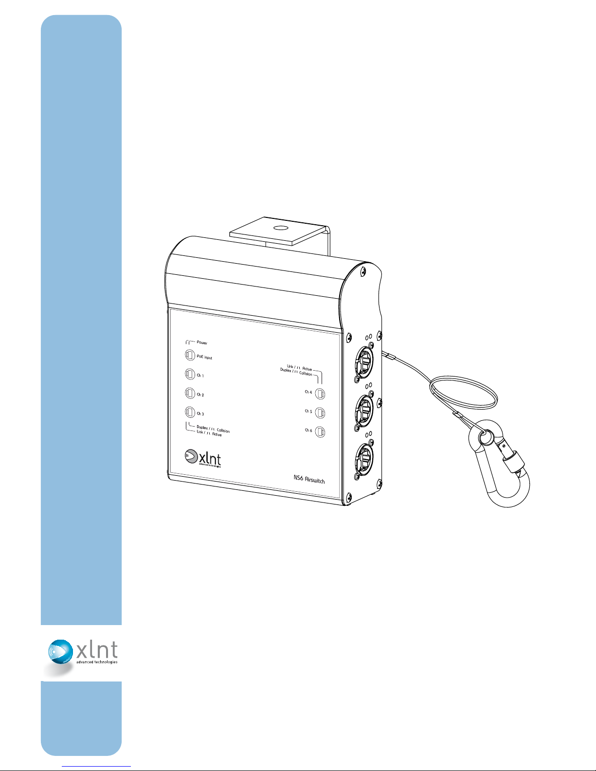
Front Panel layout
Chapter 2 Using the NS6
1 Power LED 1
2 Power LED 2
3 10/100 Mbit Power over Ethernet input port
4 10/100 Mbit Ethernet ports (6 x)
4.1 Ethernet ports
4.2 LED 1 -Link/Active
4.3 LED 2 -Duplex/Collision

16
USER MANUAL NS6/NS12P/NS12PF
Installation requirements
The NS6 Ethernet switch is designed for use with a hookclamp (not
included)
Use a clamp that is appropriate both for the object it is attached to
and the weight of the NS6 Ethernet switch.
Mount this clamp onto the bracket which is attached to the NS6
Ethernet switch with M10 Nylock nuts and M10 bolts. It may be
required to remove the bracket. Please observe the position of the
nylon and metal rings.
After attaching a NS6 Ethernet switch to a truss, secure the NS6
Ethernet switch with the supplied safety attachment.
DO NOT use a NS6 Ethernet switch in a wet/damp environment.
Chapter 2 Using the NS6

17
USER MANUAL NS6/NS12P/NS12PF
Connecting Ethernet
Use only certified Cat5, Cat5e or Cat6 cabling.
Acceptable lenghts are 95 metres with UTP cables, 50 metres with
SFTP, FTP or STP cables.
Power Requirements
The NS6 Ethernet switch is designed to receive input power via the
Ethernet connector marked as PoE Input.
The NS6 Ethernet switch needs to be connected to either an 802.3AF
compliant Power Over Lan Ethernet Switch or to be connected to a
Midspan Power Inserter. The NS6 Ethernet switch is a Class2 PoE
device. See table on page 13 for specifications.
LED signals
Power LED 1
The upper LED shows the status of the 5V power supply to the control circuits.
Power LED 2
The upper LED shows the status of the 3,3V power supply to the
control circuits.
Link/Active (per port)
When a valid network connection is established this LED will be lit.
This LED will blink when data is being transmitted.
Duplex/Collision (per port)
When a full duplex network connection is negotiated this LED will be
lit. This LED will blink when a network collision is detected on that
port.
Chapter 2 Using the NS6

18
USER MANUAL NS6/NS12P/NS12PF
(This page intentionally blank)

19
USER MANUAL NS6/NS12P/NS12PF
Chapter 3: Using the NS12P
Included Items
In the box containing this manual, the following items should be
present:
1 XLNT NS12P Ethernet switch
1 Manual (this manual)
1 Power lead
Front Panel layout
1 Power LED 1
2 Power LED 2
3 10/100 Mbit Power over Ethernet port
3.1 Ethernet port
3.2 LED 1 -Power over Ethernet active
3.2 LED 2 -Duplex/ Collision
3.4 LED 3 -Link/Active
Chapter 3 Using the NS12P

20
USER MANUAL NS6/NS12P/NS12PF
Rear Panel layout
Installation requirements
The NS12PF Ethernet switch is designed for 19” rack-mount use.
Mount the NS12PF Ethernet switch with racking screws in a 19”
cabinet. Use support strips as necessary to support the rear of the
device.
Adequate ventilation and rear-support must be provided. Allow for
enough ventilation into the 19” cabinet in which the NS12PF Ethernet
switch is mounted. Observe the environmental specifications at all
times.
When mounting a NS12PF Ethernet switch in a touring rack, a touring
rack with shock-absorbing racking strips should always be used.
Always install the NS12PF Ethernet switch on a flat surface. A maximum allowable angle of 10 degrees is acceptable.
Do not use a NS12PF Ethernet switch in a wet/damp environment.
Do not block any ventilation slot at any time.
1
2
1 Fuse holder
2 Main power input
Chapter 3 Using the NS12P

21
USER MANUAL NS6/NS12P/NS12PF
Connecting Ethernet
Ports 1 thru 12
Use only certified Cat5, Cat5e or Cat6 cabling. The connectors on the
NS12PF Ethernet switch accept both Neutrik EtherCon® and standard
RJ45 connectors
Maximum operational cable lenghts are typically 95 metres with UTP
cables, 50 metres with SFTP, FTP or STP cables.
These ports also support Power over Ethernet, with a maximum of
100 Watt allocatable power.
Power Requirements
The NS12PF Ethernet switch must be connected to a 100-240V
50-60Hz electrical power supply, with a single phase, neutral and
ground connection. For safety reasons the NS12PF Ethernet switch
must be connected to a properly grounded power outlet.
Always use the Neutrik PowerCon® power lead supplied with the
NS12PF Ethernet switch.
The power input fuse is located next to the PowerCon® input. Do not
use a different type of fuse, always replace a blown fuse by a compatible fuse.
LED signals
Power LED 1
The upper LED shows the status of the isolated 5V power supply to
the PoE control circuits.
Power LED 2
The lower LED shows the status of the 5V power supply to all other
circuits.
Chapter 3 Using the NS12P

22
USER MANUAL NS6/NS12P/NS12PF
PoE (per port)
Will be lit when a PoE compliant device is detected and connected.
When a short circuit or overload is detected this LED will be blinking
intermittendly with one pulse. When an overload is detected (maximum allocatable power reached) this LED will blink intermittendly
with 2 pulses.
Duplex/Collision (per port)
When a full duplex network connection is negotiated this LED will be
lit. This LED will blink when a network collision is detected on that
port.
Link/Active (per port)
When a valid network connection is established this LED will be lit.
This LED will blink when data is being transmitted.
Chapter 3 Using the NS12P

23
USER MANUAL NS6/NS12P/NS12PF
Chapter 4: Using the NS12PF
Included Items
In the box containing this manual, the following items should be
present:
1 XLNT NS12PF Ethernet switch
1 Manual (this manual)
1 Power lead
Front Panel layout
1 Power LED 1
2 Power LED 2
3 10/100 Mb Power over Ethernet port
3.1 Ethernet port
3.2 LED 1 -Power over Ethernet active
3.3 LED 2 -Duplex / Collision
3.4 LED 3 -Link / Active
4 1 Gbit Fiber optic port
4.1 Neutrik OpticalCon connector
4.2 LED 1 -Duplex / Collision
4.3 LED 2 -Link / Active
Chapter 4 Using the NS12PF

24
USER MANUAL NS6/NS12P/NS12PF
Rear Panel layout
Installation requirements
The NS12PF Ethernet switch is designed for 19” rack-mount use.
Mount the NS12PF Ethernet switch with racking screws in a 19”
cabinet. Use support strips as necessary to support the rear of the
device.
Adequate ventilation and rear-support must be provided. Allow for
enough ventilation into the 19” cabinet in which the NS12PF Ethernet
switch is mounted. Observe the environmental specifications at all
times.
When mounting a NS12PF Ethernet switch in a touring rack, a touring
rack with shock-absorbing racking strips should always be used.
Always install the NS12PF Ethernet switch on a flat surface. A maximum allowable angle of 10 degrees is acceptable.
Do not use a NS12PF Ethernet switch in a wet/damp environment.
Do not block any ventilation slot at any time.
1
2
1 Fuse holder
2 Main power input
Chapter 4 Using the NS12PF

25
USER MANUAL NS6/NS12P/NS12PF
Connecting Ethernet
Ports 1 thru 12
Use only certified Cat5, Cat5e or Cat6 cabling. The connectors on the
NS12PF Ethernet switch accept both Neutrik EtherCon® and standard
RJ45 connectors
Maximum operational cable lenghts are typically 95 metres with UTP
cables, 50 metres with SFTP, FTP or STP cables.
These ports also support Power over Ethernet, with a maximum of
100 Watt allocatable power.
Ports 13 and 14
Use only Neutrik supplied fiberoptic cable, with Neutrik OpticalCon®
2-pole connectors.
This cable supports Multimode 125/50 mm.
Maximum operational cable length is typically 550 metres without
couplers (1000BASE-SX Multimode)
Please use caution when bending fiberoptic cable. This type of
cabling is very sensitive to excessive bends and kinks in the glass
fiberoptic strands.
Power Requirements
The NS12PF Ethernet switch must be connected to a 100-240V
50-60Hz electrical power supply, with a single phase, neutral and
ground connection. For safety reasons the NS12PF Ethernet switch
must be connected to a properly grounded power outlet.
Always use the Powercon power lead supplied with the NS12PF Ethernet switch.
The power input fuse is located next to the PowerCon® input. Do
not use a different type of fuse, always replace a blown fuse by a
compatible fuse.
Chapter 4 Using the NS12PF

26
USER MANUAL NS6/NS12P/NS12PF
LED signals
Power LED 1
The upper LED shows the status of the isolated 5V power supply to
the PoE control circuits.
Power LED 2
The lower LED shows the status of the 5V power supply to all other
circuits.
PoE (per port)
Will be lit when a PoE compliant device is detected and connected.
When a short circuit or overload is detected this LED will be blinking
intermittendly with one pulse. When an overload is detected (maximum allocatable power reached) this LED will blink intermittendly
with 2 pulses.
Duplex/Collision (per port)
When a full duplex network connection is negotiated this LED will be
lit. This LED will blink when a network collision is detected on that
port.
Link/Active (per port)
When a valid network connection is established this LED will be lit.
This LED will blink when data is being transmitted.
Chapter 4 Using the NS12PF

27
USER MANUAL NS6/NS12P/NS12PF
Chapter 5: Troubleshooting
Power
If an NS12P or NS12PF Ethernet switch shows no power:
- Check that the power source is functional, and ground,
neutral and live connections are properly seated
- Check the power lead for damage
- Check the NS12P’s or NS12PF’s fuse
If an NS6 Ethernetswitch shows no power:
- Disconnect the NS6 Ethernet switch. Wait for 10 seconds and
apply power again
- Check that the Ethernetswitch the device is connected to
conforms to 802.3AF and that this feature is enabled (check
PoE power availability and management software)
- Check that the RJ45 Network cable coming from an 802.3 AF
compliant Ethernet Switch is seated in the port marked as
PoE Input
- Check that this cable is properly wired (all pins connected, in
the proper order) and undamaged
- Use a different cable
- Connect the NS6 Ethernet switch to a different port or a dif
ferent switch
- If no LED’s are lit contact your local XLNT service point
Data
If an NS6, NS12P or NS12PF Ethernet switch is powered, but appears not to transmit or receive data:
- Check that the Link LED of the connected port is lit. If not,
check that the cable has no shorts or broken wires, or that
the connected Ethernet device’s power source is functional,
and ground, neutral and live connections are properly
seated. Also check that this device is operational. Try
replacing the Ethernet cable, or see if another device does
communicate on the same port
- Check that the Link LED is blinking. If not, no communication
is available. Check that the connected Ethernet device is
operational and is sending data across Ethernet
Chapter 5 Troubleshooting

28
USER MANUAL NS6/NS12P/NS12PF
If an NS6, NS12P or NS12PF Ethernet switch is operational, but the
Ethernet transmission appears to be unstable:
- Check maximum operational cable lengths
- Check that the connectors of the cables have no faults
- Check that the Link/Active LED is not blinking on all ports
If so, there may be an overload of networking
communication. Try to separate signals on multiple
Ethernetswitches
- Check that the NS12P and NS12PF’s internal fan is
operational and the device is functioning within operational
environmental specifications
Hardware Failure Diagnostic
(NS12P/NS12PF Ethernet switch Only)
- Unpower the NS12P/NS12PF Ethernet switch, wait 10
seconds and apply power again. Immediately all LED’s
should be lit for 1 second.
- If a single (or more) LED is lit for 5 seconds one (or more) of
the following faults may occur:
If any of the above failures are detected the NS12P/NS12PF Ethernet
switch may be used, but should be serviced by a local XLNT service
point.
LED lit Cause Fault
PoE LED Port 1 Thermal sensor fault Fan will run at 75% speed.
If not, do not use this switch!
PoE LED Port 2 PoE IC1 failure No PoE allocation on port 1 thru 4
PoE LED Port 3 PoE IC2 failure No PoE allocation on port 5 thru 8
PoE LED Port 4 PoE IC3 failure No PoE allocation on port 9 thru 12
PoE LED Port 5 NS12 IC1 failure No Ethernet capabilities for port 1 thru 6
and (NS12PF) ports 13 and 14
PoE LED Port 6 NS12 IC2 failure No Ethernet capabilities for port 7 thru 12
Chapter 5 Troubleshooting

29
USER MANUAL NS6/NS12P/NS12PF
Appendix 1: Maintenance
Housing
Clean the exterior housing with a slightly moist, lintfree, cloth.
Do not use abrasive cleaning agents.
If a product is used in a dusty environment (or in combination with
smoke-machine oil) regular cleaning of the internal fan by qualified
personnel may be required.
Fiber optic connections
Ensure these are always kept clean. If a cable is not being used,
always use the cover to protect the connector against dirt and moisture.
Servicing
Do not open this unit.
Doing so will void warranty and might present a risk. Servicing must
be performed by qualified personnel only. Servicing is required when
the apparatus has been damaged in any way, such as power-supply
cord or plug being damaged, liquid has been spilled or objects have
fallen into the apparatus, the apparatus has been exposed to rain or
moisture, does not operate normally, or has been dropped.
Always contact your local XLNT dealer for instructions to obtain
service.
Appendix 1 Maintenance

30
USER MANUAL NS6/NS12P/NS12PF
Appendix 2: Specifications
NS6 Mechanical
Size (physical), WxHxD 140 x 170 x 60 mm
Weight (physical) 0,9 Kg
Ingress protection rating IP50
NS6 Electrical
Input voltage, frequency According to IEEE 802.3AF
Power rating 6 Watt max (Class 2)
NS12P & NS12PF Mechanical
Size (physical), WxHxD 480 x 44 x 210 mm
Weight (physical) (NS12P) 3,0 Kg
Weight (physical) (NS12PF) 3,2 Kg
Ingress protection rating IP20
NS12P & NS12PF Electrical
Input voltage, frequency 100-240V AC 50-60Hz
Power rating 120 Watt (max)
Fuse 2,5 A SlowBlow, 20 x 5mm
Environmental specifications
Operational Temperature 0-45 deg. C
Storage Temperature -10 – +60 deg. C
Humidity 10-90% (non condensing)
Operational Altitude 2400m max
Storage Altitude 6000m max
Acoustic (NS12P & NS12PF only)
Sound level, full load,
at t-ambient 25ºC 44dB(A) at 1 metre
Sound level, full load,
at t-ambient 45ºC 50dB(A) at 1 metre
Appendix 2 : Specifications


USER MANUAL NS6/NS12P/NS12PF
International Sales office:
XLNT Advanced Technologies
Tel +31 30 247 99 99
Fax +31 30 247 99 98
info@xlnt-at.com
www.xlnt-at.com
Manual rev. 2.0, Jan 2008
 Loading...