

XLifter X1 User Manual

World’s first
Air-suspension controller with self-levelling feature
for the D3, D4 and RRS Land Rover vehicles
User manual
(Installation & user guide)

Table of contents:
1. Legal disclaimer 2
2. General description 2
3. Safety information 3
4. Installation 4
4.1. Package Contents 4
4.2. Installation - general description and overview 4
4.3. EAS Unit Installation 5
4.4. Control Module Installation 8
4.5. Vehicle type and calibration settings 9
4.6. Dismantling XLifter from vehicle 9
5. Instruction for use 10
5.1. Function Lifter: Height adjustment in predefined programs. 10
5.2. Function Lifter – free: Adjustment from -40 to +75 mm in 5 mm steps. 11
5.3. Function levelling: self-level the vehicle. 12
5.4. Menu “Settings”: User settings. 14
6. Calibration 15
7. Service menu 16
7.1. Entering the Service menu 16
7.2. Service menu items description 17
8. Firmware update 18
9. Technical specifications 20
10. FAQ & Troubleshooting 21
11. Warranty conditions 23
12. Contacts and support 23
Quick orientation in this manual:
Congratulations, you are actually reading the manual! I'm so glad you decided to read the
instructions to your new XLifter. Many users casually dismiss instructions and seek to
figure it out on their own – which is perfectly possible, we all do! But, even then I’ve built
the product as simple and intuitive as possible, there are some useful tricks, hints,
warnings and “behind the scenes” info, which I’ve collected over the years for you into this
manual. It’s worth to read it. Dig in, mark it up, cut out your favourite sections. It's going to
be a wild ride.
Chapter 4 is all about installation, skip it if the XLifter is already installed. The most
important is the chapter 5 - Instruction for use, where the XLifter daily-use functions are
described. Please consider reading it again after a few days of hands-on experience.
XLifter model X1, user guide, ver. 1.41, firmware ver. 0.98
Reco, spol. s.r.o., Na hlinach 6, 18200 Prague, Czech Rep., https//www.xlifter.com, info@xlifter.com Page 1

1. Legal disclaimer
You are hereby provided with an air-suspension controller for Land Rover vehicles – product named
XLifter (hereinafter as the „device” or „XLifter“).
XLifter is an additional device able to change the air-suspension adjustment and able to change
other parts of your car set-up by the car´s manufacturer.
XLifter is not a device approved and designed for installation into vehicles intended to be operated
on public roads namely pursuant to Act. no. 361/2000 Coll, as amended. The manufacturer does not
assume any liability deriving from technical requirements for operation of vehicles on public roads
in case you decide to use this product in traffic on public roads or anywhere else, where operation
of this device may be considered as unauthorized, whether in the Czech Republic or in any other
jurisdiction. The end-user assumes all liability connected to use of the device on public roads,
derived namely from the mandatory technical requirements for operation of vehicles on public
roads provided by Act. No. 56/2001 Coll and regulation no. 341/2014 Coll.
By installation of the device the end-user discharges the manufacturer from any liability connected
to any influence or damage (whether financial or immaterial) of the provided product on other
systems, parts or components of the vehicle (whether mechanical or electronical). By installation of
this product the end-user also acknowledges that this product is meant to be used in controlled
conditions, namely at low speeds and with increased caution.
The end-user undertakes to inform about installation of the device any prospective future owner of
the respective vehicle equipped with the device.
By installation of the device you acknowledge the above-mentioned and agree with the abovementioned terms. Please use the XLifter only in off-road conditions and not on public roads.
2. General description
XLifter is an advanced air-suspension controller for the Land Rover vehicles. XLifter allows
you to take the air suspension capabilities of your Land Rover to the maximum, making
your off-roading or expedition travelling greater experience.
XLifter gives you more detailed control over the vehicle height settings. Raising the
vehicle, even above the „Off-road“ height, helps you to tackle difficult terrain. XLifter is not
limited by the 40 Km/h speed limit, so travelling over long stripes of sand, green lanes or
dirty roads will be fun more fun. Also, XLifter keeps selected lift settings permanently, you
can fit bigger tires easily. Lowering the vehicle slightly improves cornering stability and
aerodynamics. Lowering below the original access height makes possible the entering of
low-clearance garages or ferries and makes cargo loading easier.
XLifter unique self-levelling feature makes your in-car or in a roof top tent sleeping more
comfortable while expedition travelling.
XLifter controls are intuitive and comfortable. The control module with graphical OLED
display and physical buttons was optimized for off-road handling.
XLifter EAS unit communicates with the control module wirelessly. Installation to your
vehicle is simple and XLifter is fully removable. No drilling, soldering, or in-car wiring is
required.
XLifter is designed for Land Rover Discovery 3 (LR3), Discovery 4 (LR4) and Range Rover
Sport (model L320) vehicles.
XLifter model X1, user guide, ver. 1.41, firmware ver. 0.98
Reco, spol. s.r.o., Na hlinach 6, 18200 Prague, Czech Rep., https//www.xlifter.com, info@xlifter.com Page 2

3. Safety information
This manual contains important information on the installation (in the installation guide) and use of
the XLifter. Please take some time to read this manual to take full advantage of the XLifter features
and to ensure that you know how to operate them safely. Use the XLifter only for its intended
purpose as described in this user manual.
What the safety symbols in this user manual mean:
This symbol represents potential general warnings, hazards or unsafe practices that may
result in possible damage to vehicle or vehicle systems. Please read texts marked by this
symbol carefully and proceed according to provided instructions to avoid risks.
Warning: This symbol, with the word "warning" attached above or next to the symbol,
indicates situations where non-compliance may result in serious injury or damage to the
equipment or vehicle.
Safety instructions are described on a continuous basis in the description of each XLifter function.
However, below is an overview of the most important ones:
General warnings:
Warning: Ensure that the XLifter is operated only by a person familiar with this manual. If
another person is driving, please activate the Keylock function before, as a safety measure.
(see chapter 5.4)
Warning: If an XLifter is left installed in the vehicle when it is sold, notify the new acquirer
and familiarize him with this manual. Please keep this manual permanently in the vehicle
in an accessible location for a future reference.
Warning: Do not use XLifter while driving on the public roads. Do not lower or raise the
vehicle at high speeds.
Warnings for the lifter and lifer-free functions:
Warning: when in extreme lifts - “Sky Rocket” (+75 mm) or any lift program while the
“original” vehicle height is Off Road, please be gentle with the accelerator pedal in case,
when you have low-range engaged and you are steering hard to the left or right. The
driveshafts to CV joints angle is very high. Don’t overstress the CV joints.
Warning: In the original “Off Road” vehicle height, it is not recommended to lift the vehicle
with XLifter by more than +25 mm permanently due to possible increase wear of the airsprings.
Be gentle to the vehicle compressor! The compressor will overheat when the vehicle is
lowered/raised several times (3x is usually enough) in a row. When overheated, the Land
Rover EAS unit inhibit further operation until cooled. Cooling takes about 10 minutes.
Warning for the levelling function:
Warning: NEVER EVER start the levelling function while driving!!! The wheels height will
be set differently, which results to potentially dangerous situation. Start levelling only when
the vehicle is stationary!
When active, the levelling function must be exited before driving! Otherwise you start
driving with unbalanced wheel heights, exposing yourself to potentially dangerous
situations and you may even damage your vehicle! NEVER leave the camping place with
levelling still active!
Do not engage electronic park break (EPB) before or during levelling. It will cause
unnecessary tension in park break cables, which will counteract wheel movement. You
may use the “P” gear instead in the automatic gearbox vehicles.
Warning: Close all doors before starting the levelling function to prevent possible damage
due to contact with surrounding ground.
XLifter model X1, user guide, ver. 1.41, firmware ver. 0.98
Reco, spol. s.r.o., Na hlinach 6, 18200 Prague, Czech Rep., https//www.xlifter.com, info@xlifter.com Page 3

4. Installation
1x XLifter EAS installation
1x Cable harness with the bypass connector
1x XLifter
control module
1x Velcro strip for easy control module installation
1x User and installation manuals
1x XLifter sticker
4.1. Package Contents
4.2. Installation - general description and overview
The XLifter device consists of 2 main components - the control module and the EAS
installation unit (EAS stands for Electronic Air Suspension). The control module (display
unit with buttons) is used to control all settings and to inform the user of the operating
status. The EAS unit serves to adjust the wheel height sensor signals and vehicle tilt
measurements. Communication of the control module and the EAS unit is wireless.
The control module is installed anywhere in a suitable place in the interior of the vehicle.
The control module needs to be connected to an ignition-switched 12V power supply
(cigarette lighter socket). Advanced users may cut the power connector and connect the
cable to appropriate 12V junction point. Installation with all cables hidden will look more
aesthetically and the lighter socket will not be blocked.
The XLifter EAS unit is installed near the original air suspension control unit and connects
with it via the supplied cable harness. The XLifter EAS unit is mechanically attached to the
body of the vehicle after installation, thus serves also as an accurate tilt sensor.
Quick installation overview in 5 steps:
1. Install the XLifter EAS unit and connect the cable harness
2. Plug the control module power to 12V socket
3. Set the appropriate vehicle type (D3, D4, RRS)
4. Set the Steering position (left or right-hand side)
5. Perform the calibration procedure
XLifter model X1, user guide, ver. 1.41, firmware ver. 0.98
Reco, spol. s.r.o., Na hlinach 6, 18200 Prague, Czech Rep., https//www.xlifter.com, info@xlifter.com Page 4
4.3. EAS Unit Installation
The installation procedure of the EAS unit is listed for the Discovery 3/4 vehicle. For the
Range Rover Sport, the original EAS control unit is located about 10cm lower than in the
Discovery. For convenient access to the connectors, it is necessary to remove the footwell
and the adjacent left panel (the one with the front bonnet open handle).
Estimated installation time:
●
The EAS unit installation should take approximately 10 - 30 minutes.
Tools required:
●
Common cross-head screwdriver (e.g. original from Land Rover equipment).
●
Flashlight - Installation area lighting
EAS unit installation procedure:
1. Disconnect the vehicle battery according to the vehicle user manual
a. Make sure the ignition is off.
b. Disconnect the + pole.
c. Wait 1 minute.
Note: This point is not required, installing without disconnecting the battery does not
cause problems.
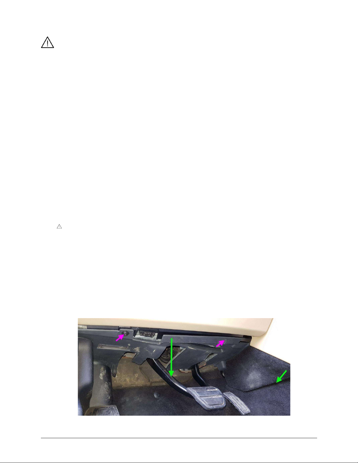
2. Dismantle the lover dashboard cover panel under the steering wheel.
If installing to the Range Rover Sport L320, see the note above.
a. Unscrew the two screws holding the cover.
b. Pull in the direction of the RIGHT green arrow (see picture below) to release a
mechanical connector connecting the cover to the central tunnel.
c. Hold the cover panel in the centre. Pull down and towards you slightly to move
the cover panel down for approximately 10 centimetres.
d. Disconnect the light connector located on the left side (right for RHD vehicles) of
the cover.
e. Remove the entire cover.
XLifter model X1, user guide, ver. 1.41, firmware ver. 0.98
Reco, spol. s.r.o., Na hlinach 6, 18200 Prague, Czech Rep., https//www.xlifter.com, info@xlifter.com Page 5

3. Disconnect wiring harnesses from the original LANDROVER EAS unit
The Land Rover EAS unit is located at the left
(right for RHD vehicles) inner side of car
body – approx. in the middle of imaginary
line between the end of A pillar and drivers
footrest.
Use a flashlight to illuminate the work area.
a. Disconnect the A and B connectors.
Disconnect the connector by pushing the connector lock and pulling it
outwardly (with some light wobbling). The A and B connectors are the most left
and right ones.
b. Place the disconnected cable harnesses temporarily behind the rest of the cables
in area. This will help you to create enough space for a comfortable XLifter EAS
unit installation.
4. Install the XLifter EAS unit
Prior to sticking the XLifter EAS unit into its final position, it may be a good idea to
practice placing the EAS unit to a correct position for a few times, without having
removed the 3M reclosable fastener protective foil. The 3M fastener sticks very firmly
once placed in a position and makes it very uneasy to replace it once stuck in a place.
The XLifter EAS unit is equipped with a tilt sensor. The unit must be positioned at least
approximately according to the procedure described. Otherwise (sticking it horizontally
or "upside down"), the leveling function will not work properly.
a. On the unprinted side of the EAS
unit, remove the adhesive protection
foil from the 3M fasteners.
b. Place and stick the XLifter EAS unit
to the original Land Rover EAS unit
as shown.
The printed side of the unit faces the
●
centre tunnel.
The arrow marked THIS SIDE UP is
●
pointing up.
For the sticking itself, it takes a few
●
seconds with strong force required.
XLifter model X1, user guide, ver. 1.41, firmware ver. 0.98
Reco, spol. s.r.o., Na hlinach 6, 18200 Prague, Czech Rep., https//www.xlifter.com, info@xlifter.com Page 6

5. Connect the XLifter cable harness
a. Connect the connectors A(out) and B(out)
of the supplied cable harness to the original
Land Rover EAS unit.
b. Plug the previously disconnected
connectors to the connectors A(in) and
B(in) of the supplied cable harness.
c. Plug the connector C to the XLifter EAS
unit.
NOTICE:
Place the "loose" cables in a way so they do
not move freely. If necessary, use any
tightening strap (not included). This
prevents them from "knocking out" in longterm operation.
None of the connectors are
interchangeable. You cannot connect the
cable harnesses in a wrong way.
All connectors must be fully inserted as
far as they will go, as shown. Some
connectors, especially B ones, require
slightly more force to fully connect.
Incomplete insertion is the source of unpredictable problems, please pay
attention here!
6. Connect the vehicle battery in accordance with the vehicle user manual
Only if you disconnected it in step 1.
●
Discovery 4: The “Suspension error” will be displayed. Cycle the ignition to clear it.
●
●
Discovery 3: The “Suspension error” should clear itself in few seconds.
7. Check the status LED on the XLifter EAS unit
The green status LED flashes at a fast pace - 2x per second, indicating readiness for
●
operation and awaiting wireless connection from the control module.
XLifter model X1, user guide, ver. 1.41, firmware ver. 0.98
Reco, spol. s.r.o., Na hlinach 6, 18200 Prague, Czech Rep., https//www.xlifter.com, info@xlifter.com Page 7
 Loading...