

Page 1

Bicycle
Computer
CY-533 Manual
E
Page 2

Contents
1. Item List 1
2. Operation 2
3. Nomendature 5
4. Main Screen Display 6
5. Basic Setting
5.1. Clock/speed setting mode 7
5.1.1. KM/H or ML/H 8
5.1.2. TIMER COUNT UP or TIMER COUNT DOWN 8
5.1.3. TRIP COUNT UP or TRIP COUNT DOWN 9
5.1.4. CLOCK 9
5.1.5. BIKE 1 or BIKE 2 10
5.1.6. WHEEL SIZE 10
5.1.7. TEMPERATURE 11
5.1.8. GENDER / SEX 11
5.1.9. KG or LB 11
5.1.10. WEIGHT 12
5.1.11. LANGUAGE 12
5.2. Altitude mode setting 13
5.2.1. ACTUAL ALTITUDE 14
5.2.2. HOME ALTITUDE 14
5.2.3. RE-CALIBRATING THE ALTIMETER 15
6. Basic Function Indication
6.1. Clock/speed function 16
6.1.1. ACTUAL ALTITUDE 17
6.1.2. TIMER COUNT UP/TIMER COUNT DOWN 17
6.1.3. TRIP TIME 18
6.1.4. AVERAGE SPEED 18
6.1.5. MAXIMUM SPEED 19
6.1.6. TIME BIKE 1 19
6.1.7. TIME BIKE 2 20
6.1.8. TOTAL TIME 20
6.1.9. TRIP COUNT UP/TRIP COUNT DOWN 21
6.1.9.1. TRIP DISTANCE 21
6.1.9.2. ODO BIKE 1 22
6.1.9.3. ODO BIKE 2 22
6.1.9.4. TOTAL ODO 22
6.1.9.5. KCAL 23
6.2. Altitude/Cadence functions 24
6.2.1. MAXIMUM ALTITUDE 25
6.2.2. TRIP CLIMB 25
6.2.3. ALTITUDE BIKE 1 25
6.2.4. ALTITUDE BIKE 2 26
6.2.5. TOTAL ALTITUDE 26
6.2.6. ALTITUDE GAIN or ALTITUDE LOSS 27
6.2.7. AVERAGE GRADIENT 27
6.2.8. MAXIMUM GRADIENT 28
6.2.9. AVERAGE CADENCE 28
6.2.10. MAXIMUM CADENCE 28
6.2.11. TRIP CADENCE 29
6.3. Clear functions 29
7. ID Scan For Coded Speed 32
8. Low Battery Indication 34
9. Battery Replacement 34
10. Troubleshooting 35
11. Specications 36
12. Limited Warrenty 37
13. Important Health Notice 38
14. Wheel Size Chart 39
Page 3
Bicycle Computer
Chapter 1
Chapter 2
Item list Operation
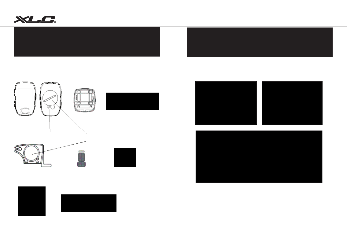
Please check that all the following items have been included with your
cycle computer before starting.
CY-533AC series
cycle computer
Air Pressure
Cadence & Speed
Sensor
Bracket
Battery Cover
Magnet
Nylon ties
Magnet for Cadence
2.1 attaching bracket on the handle bar
Rubber
1
Stabling Pads
2
Page 4
2.2 attaching speed sensor/magnet on bicycle
Bicycle Computer
Installing the Cadence Magnet
Put the Cadence Magnet on the Crank and
must face Cadence Sensor
Note: The max distance between the Cadence
sensor and Magnet should be within 5mm.
Installing the Cadence & Speed Sensor
Check the right side of the Chain Stay to
nd the suitable point to attach the Cadence
& speed sensor. The distance between
cycle computer & the sensor would be
within 150 cm.
Installing the Speed Magnet
Put the Speed Magnet on the left spokes
of the back wheel and must face the speed
sensor.
Note: Turn the speed handle to adjust speed sensor. The Max distance between speed sensor and
Magnet should be within 1mm~5mm.
3
Please check green light on the Cadence
& Speed sensor to make Bitmap sure 2
functions operated normally when riding your
bicycle at rst time.
Note: Please turn around the wheel to check
the green light on the sensor, Initial ashing
green light indicates the sensor detected
magnet signals normally.
4
Page 5
Bicycle Computer
Chapter 3
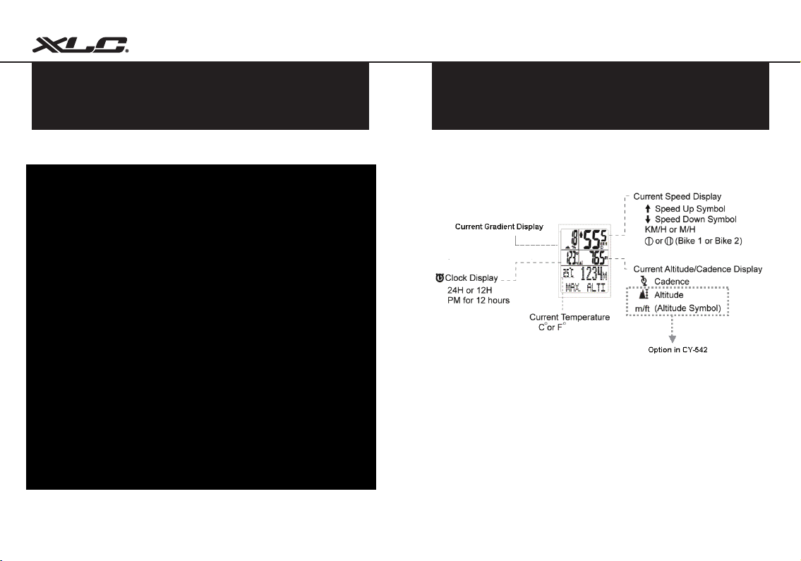
Nomenclatur
Chapter 4
Main Screen Display
5
6
Page 6
Chapter 5
Basic Setting
Before starting the device, please set the basic settings in advance to get more accurate and useful
information from device.
Bicycle Computer
5.1 Clock/Speed Setting mode
Press M key to get into clock/speed mode.
Under any mode, press S key for 2 seconds.
Screen
5.1.1
5.1.105.1.11
7
5.1.2
5.1.9
5.1.3
5.1.8
5.1.4
5.1.7
5.1.5
5.1.6
5.1.1 KM/H or ML/H
The user can select the unit for speed which will
be displayed on the screen.
• Under KM/H or ML/H, press C key or A key to
switch one another.
• Press M key to transfer next setting!
5.1.2 TIMER COUNT UP or TIMER COUNT DOWN
The user can select TIMER COUNT UP or TIMER
COUNT DOWN. After selects the unit, it (COUNT
UP / COUNT DOWN) will display.
• Under TIMER COUNT UP or TIMER COUNT
DOWN, press C key or A key to switch
another one.
• Press A key or C key to adjust number.
• Press M to transfer next setting!
8
Page 7
Bicycle Computer
5.1.3 TRIP COUNT UP or TRIP COUNT DOWN
The user can select TRIP COUNT UP or TRIP
COUNT DOWN in the setting mode. After selects
the function, it (TIMER UP / TIMER DOWN) will
display.
• Under TRIP COUNT UP or TRIP COUNT DOWN,
press A key or C key to switch one another.
5.1.4 CLOCK
Under SET CLOCK
• Press A key or C key to adjust number (12H, 24H, hour,
minute, second).
• Press M to transfer next setting!
9
• Under TRIP COUNT DOWN,
press M key to set up
distance for TRIP COUNT
DOWN.
• Press A key or C key to
adjust number .
• Press M to transfer next
setting!
5.1.5 BIKE 1 or BIKE 2
CY-533AC contains two bike setting, it allows the user to
use this device for two bikes with different wheel size.
Under BIKE 1 or BIKE 2
• Press A key or C key to adjust number
• Press M to transfer next setting!
5.1.6 WHEEL SIZE
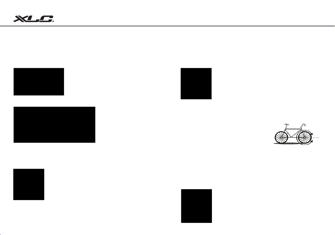
To get the accurate result from the device for speed
value or other information, the wheel size must be
correct. Mark the symbol on the tire and ride one
circle. Then measure the length between two points
that result comes out. Or determine the wheel
circumference by the following equation:
Circumference (mm) = 2x3.14xR (inch) x2.54 (1 inch = 2.54 cm)
R=Radius in centimeter
Please also refer the “wheel size chart” on the last page to nd out the wheel
size.
Under WHEEL SIZE
• Press A key or C key to adjust number
• Press M to transfer next setting!
10
Page 8
Bicycle Computer
5.1.7 TEMPERATURE
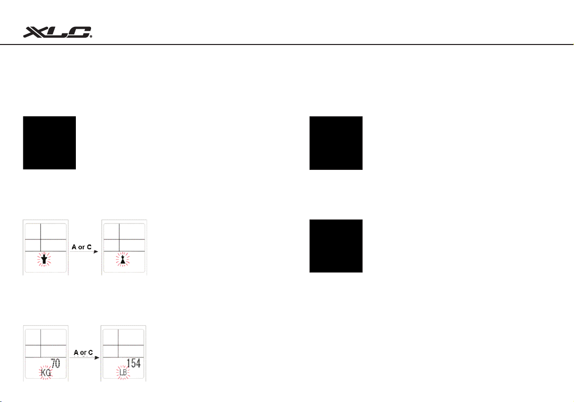
5.1.8 Set Sex
5.1.9 Set KG or LB
11
The user can select temperature unit (°C or °F) that will be
display on the screen.
Under Temperature
• Press A key or C key to adjust number.
• Press M to transfer next setting!
Under Set Sex
• Press A key or C key to adjust
symbol of male or female.
• Press M to transfer next setting!
Under Set KG or LB
• Press A key or C key to adjust
weight symbol.
• Press M to transfer next setting!
5.1.10 Set Weight
5.1.11 LANGUAGE
Under Set Weight
• Press A key or C key to adjust number.
• Press M to transfer next setting!
CY- 533AC offers 5 different languages (ENGLISH,
FRANCAIS, DEUTSCH, ITALIANOL, ESPANOL)
for the user to choose, after selecting the preferred
language, all the displays will change to the selected
language.
Under LANGUAGE
• Press A key or C key to switch language.
• Press M to transfer next setting or press S key for 2
seconds to leave setting mode.
Note: under any setting mode, press S for 2 seconds to leave setting
mode!
12
Page 9
Bicycle Computer
5.2 Altitude Mode Setting
Press A key to get into altitude mode.
Under any altitude functions, press S key for 3
seconds.
13
5.2.1 5.2.2
5.2.1 ACTUAL ALTITUDE
Because air pressure will inuenced by temperature or
weather changes while goes out for a ride. In order to
correct the inuence of the weather change or temperature
changes, the user can also adjust the actual altitude on CY533AC. If the user sees a road sign indicating actual altitude
that is differ from the actual attitude value on the device, the
user may adjust actual altitude according to the sign.
Under ACT. ALTI
• Press A key or C key to adjust actual alatitude.
• Press M to transfer next setting.
5.2.2 HOME ALTITUDE
The “home altitude” is the altitude of the starting location
(home or starting point). This value can be found by maps,
internet or newspaper. Once the number is entered into
CY-533AC. It will calculate automatically. The accurate
calculation of altitude requires the precise information for
home altitude. To make CY-533AC indicating altitude and
climbing more precisely, home altitude must be set up in
advance.
• Press A key or C key to home altitude.
• Press M to transfer next setting.
14
Page 10
Bicycle Computer
Chapter 6
5.2.3 RE-CALIBRATING THE ALTIMETER
Due to change in local barometric pressure inuenced by temperature and wind,
the user may notice the ending altitude is different from the home altitude as day
goes by. It is normal because of pressure inuences over time. So before goes
out for a ride, we suggest to call back the home altitude value in CY-533AC.
Any Mode
A & C > 2 sec
• Under any mode, press and hold A key and C key at same time for 3 sec until
“SET HOME” display.
• The user can call back the value for home altitude you have entered before at any
time.
Basic Functions Indication
Before starting the device, you need to get more details information about each functions!
6.1 Clock/Speed Functions
Press M key to get into clock/speed functions.
Display Changes
CY-533AC has 4 different modes with individual functions to use for cycling.
15
16
Page 11
6.1.1 ACTUAL ALTITUDE 6.1.3 TRIP TIME
Bicycle Computer
Sub-function of clock/speed function.
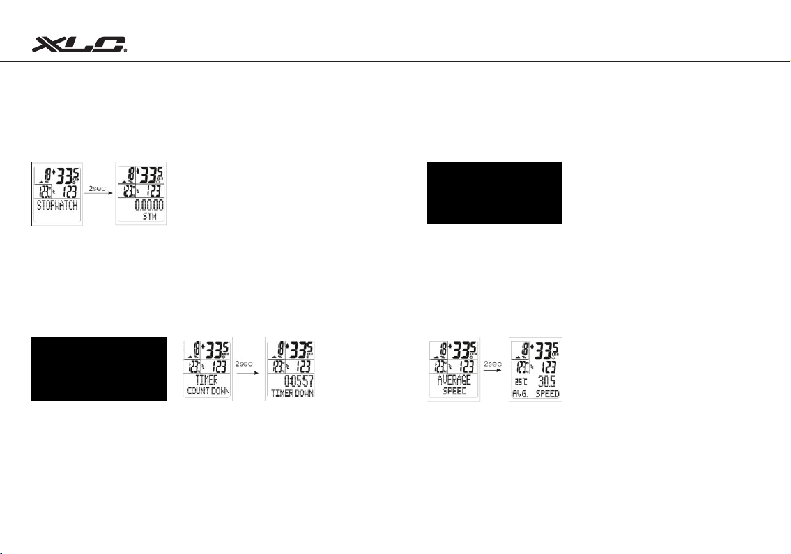
The user can press C key to start or stop the function of stopwatch,
To clean the time, by holding C key for 3 seconds.
6.1.2 TIMER COUNT UP/TIMER COUNT DOWN
Sub-function of clock/speed function.
Timer count up: The timer will increase while riding the bicycle.
Timer count down: The timer will decrease towards zero while riding the bicycle.
The user can set up the count down time in the setting mode.
NOTE
The user can select count up or count down in the setting mode.
After selects the display method, it (TIMER UP / TIMER DOWN) will display!
17
Sub-function of clock/speed function.
Displays the user’s trip time from the beginning to the current point.
6.1.4 AVERAGE SPEED
Sub-function of clock/speed function.
Displays the user’s average speed from the beginning to the current point .
18
Page 12
6.1.5 MAXIMUM SPEED 6.1.7 TIME BIKE 2
Bicycle Computer
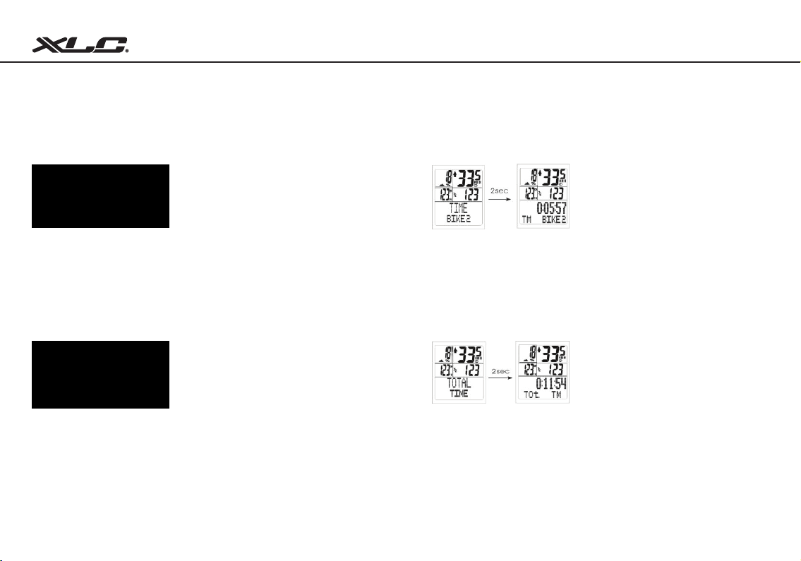
Sub-function of clock/speed function.
Displays the user’s maximum speed from the beginning to the current point .
Sub-function of clock/speed function.
Displays the total riding time for Bike 2.
6.1.6 TIME BIKE 1 6.1.8 TOTAL TIME
Sub-function of clock/speed function.
Displays the total riding time for Bike 1.
19
Sub-function of clock/speed function.
Displays the total riding time (Bike 1+ Bike 2).
20
Page 13
Bicycle Computer
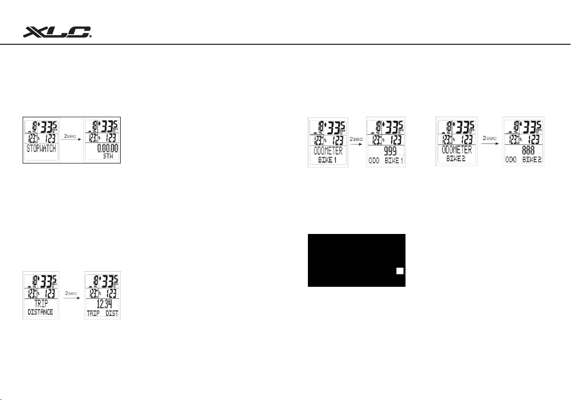
6.1.9 TRIP COUNT UP/TRIP COUNT DOWN
Sub-function of clock/speed function.
Trip count up: The distance will increase while riding the bicycle.
Trip count down: The distance will decrease towards zero while riding the
bicycle.
The user can set up the count down distance in the setting mode.
NOTE
The user can select count up or count down in the setting mode.
After select the display method, it (TRIP COUNT UP / TRIP COUNT DOWN) will display.
6.1.9-1 TRIP DISTANCE
Sub-function of clock/speed function.
Displays the user’s trip distance from the beginning to the destination.
21
6.1.9-2 ODO BIKE 1
Sub-function of clock/speed function.
Displays the odometer of rst wheel
size setting.
6.1.9-3 ODO BIKE 2
Sub-function of clock/speed function.
Displays the odometer of second
wheel size setting.
6.1.9-4 TOTAL ODO
Sub-function of clock/speed function.
Displays the total odometer of bike1 + bike 2.
NOTE
The number can not be erased by clear function, CY-533AC will keep the value of ODO
BIKE1, ODO BIKE2 and Total Odometer in the memory even after the user changes new
battery.
22
Page 14
6.1.9-5 KCAL 6.2 Altitude/Cadence Functions
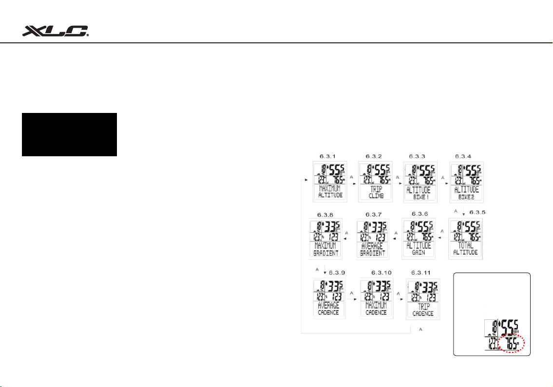
The CY-533AC uses barometric air pressure to measure the altitude.
It can convert the data from current barometric pressure into the respective
altitude.
SCREEN DISPLAY CHANGE
Bicycle Computer
ACTUAL AlTITUDE
The “actual altitude” is the altitude of
the location where the user currently
is. It is different from the home altitude. The altitude information signs
can usually be founded when
riding ascending the mountain or
traveling.
Please Do not insert any sharp objects into the measurement hole. These holes must always stay open and
23
clean.
24
Page 15
Bicycle Computer
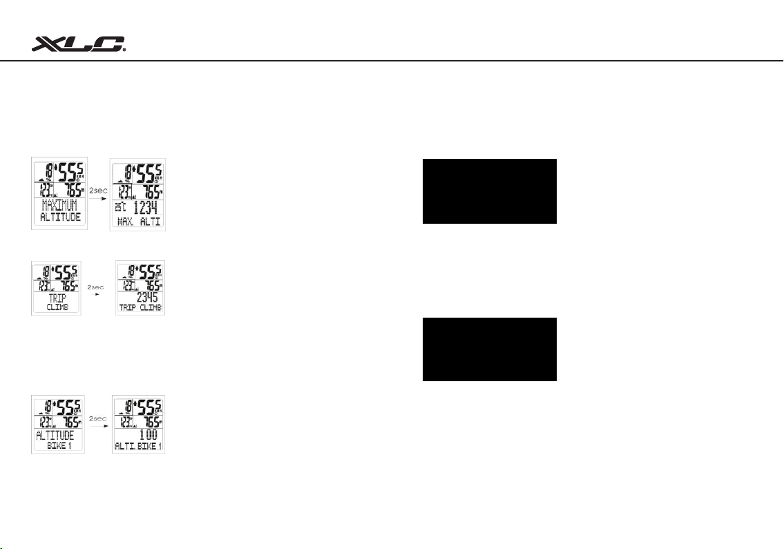
6.2.1 MAXIMUM ALTITUDE
Displays the maximum altitude for the trip.
6.2.2 TRIP CLIMB
The “TRIP CLIMB” tells the user the current climbing value for this trip.
( TRIP CLIMB will increase only when riding uphill )
NOTE
If the climbing does not reach more than 4 meters, trip climb will not increase.
6.2.3 ALTITUDE BIKE 1
If the user is riding under rst setting of BIKE1, ALTI.BIKE1 will display the total
Altitude value for BIKE1
NOTE
This value cannot be erased by the clear function, unless apply the default setting.
(Refer to Default Setting Section)
25
6.2.4 ALTITUDE BIKE 2
If the user is riding under rst setting of BIKE2, ALTI.BIKE2 will display the total
Altitude value for BIKE2
NOTE
This value cannot be erased by the clear function, unless apply the default setting.
(Refer to Default Setting Section)
6.2.5 TOTAL ALTITUDE
Display total altitude value of bike1 + bike2
NOTE
This value cannot be erased by the clear function, unless apply the default setting.
(Refer to Default Setting Section)
26
Page 16
Bicycle Computer
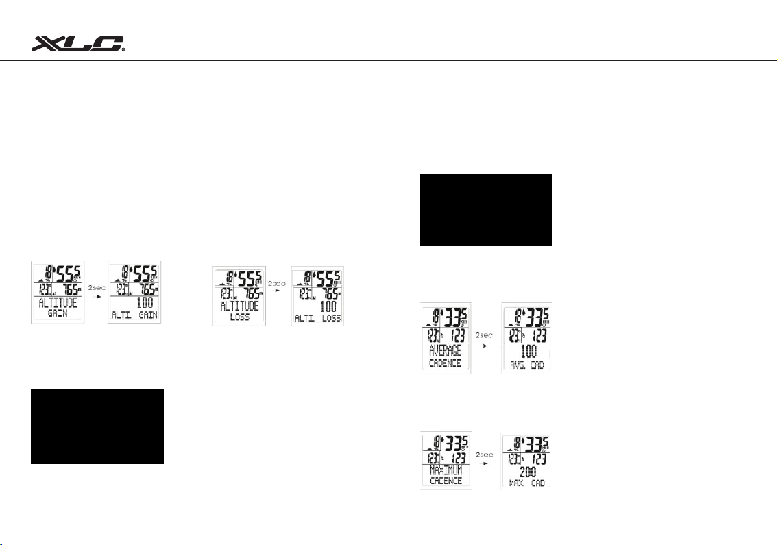
6.2.6 ALTITUDE GAIN or ALTITUDE LOSS
Altitude gain and loss tells the user how high or low current riding is.
Altitude Function can be set into two systems. The metric system (m/min) or
British system (feet/min)
If the user is riding uphill, the screen will display ALTI.GAIN. with value
increasing.
If the user is riding downhill, the screen will display ALTI. LOSS. with value
decreasing.
6.2.7 AVERAGE GRADIENT
Display average gradient from the beginning to the current point.
27
6.2.8 MAXIMUM GRADIENT
Display maximum gradient from the beginning to the current point.
6.2.9 AVERAGE CADENCE
Display average cadence from the beginning to the current point.
6.2.10 MAXIMUM CADENCE
Display maximum cadence from the beginning to the current point.
28
Page 17
Bicycle Computer
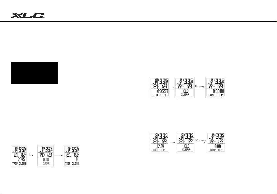
6.2.11 TRIP CADENCE
It display total cadence for one trip.
Under TRIP CADENCE, press C key for 2 seconds
(AVERAGE CADENCE, MAXIMUM CADENCE, TRIP CADENCE will return to
zero)
6.3 CLEAR FUNCTIONS
Using C key (clear button) to make the value to return zero!
Clear The Measured Value For Altitude Function
Under TRIP CLIMB,press C key for 2 seconds
(MAXIMUM ALTITUDE, TRIP CLIMB, ALTITUDE GAIN, ALTITUDE LOSS
will return to zero.)
29
Clear The Measured Value For Timer Count Up / Timer Count Down
Under TIMER COUNT UP or TIMER COUNT DOWN, press C key for 2
seconds
(TIMER COUNT UP will return to zero or TIMER COUNT DOWN will return to
default setting.)
Clear The Measured Value For Trip Count Up / Trip Count Down
Under TRIP COUNT UP or TRIP COUNT DOWN, press C key for 2 seconds
(TRIP COUNT UP will return to zero or TRIP COUNT DOWN will return to default
setting.)
30
Page 18
Bicycle Computer
Chapter 7
ID Scan for Coded Speed
Clear The Measured Value For Average Cadence, Maximum Cadence, Trip
Cadence At The Same Time
Under TRIP CADENCE, press C key for 2 seconds
(AVERAGE CADENCE, MAXIMUM CADENCE, TRIP CADENCE will return to
zero.)
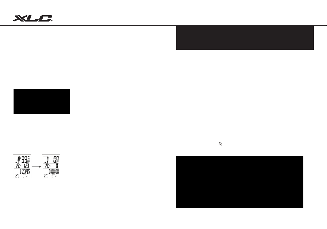
Clear All The Measured Value Except ID Codes by DEFAULT SETTING
Under STOPWATCH MODE, press and hold all M S C keys at the same time
for 6 sec until all the values return to default values.
The default setting will keep the ID Code and the Clock after all the default
values.
31
The advange of 2.4Ghz wireless transmitting technology is stablized signals
from the chest belt or speed sensor to the cycle computer. CY533AC can avoid
noise interference from other devices while it is working with speed sensor.
Each device and sensor has been ID SCAN after manufacturing.
So the user can start to use the product immediately without doing ID SCAN.
The main purpose of ID SCAN is to pair up the cycle computer to its speed/
cadence sensor as well as to prevent signals and cross talk from other cycle
computers. Each cycle computer set has been pre-ID Scan right after it’s
produced, so the users do not necessarily need to run ID-SCAN after their
purchase. The users would need to run ID-SCAN as if additional speed/cadence
sensor are being replaced or for purpose of second bike uses.
NOTE
The BIKE1&BIKE2 can coordinate with one individual code from one speed sensor or two
individual codes with additional speed sensor, chest belt respectively.
Under any mode, press A key and C key at same time for 6 sceonds.
When the percentage of shows 100% means scan completed.
(Please note that speed sensor have to be in wake up mode)
32
Page 19
Bicycle Computer
Chapter 8
Low Battery Indication
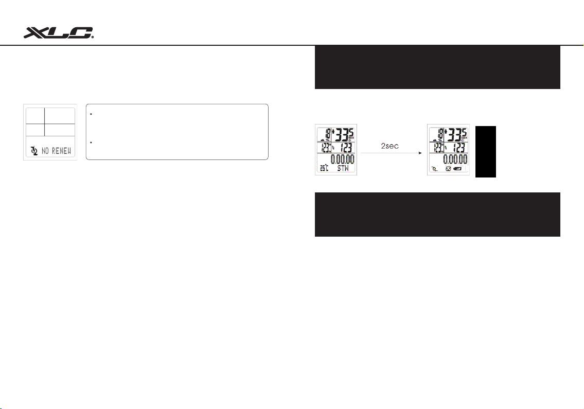
If “NO RENEW” sign shows on the displayer
when scan completed, it means ID scan failure.
The user may press C key again to scan again.
The mode returns to Clock mode after 30
seconds automatically.
If low power for the battery, under Clock mode CY-533AC will display the signal
to indicate the low battery information.
Low power for speed
sensor
Low power for watch
Chapter 9
Battery Replacement
CY-500 series computer:
Unscrew the back cover. The (+) side should be facing up. Gently remove the
battery and replace it with a new battery model CR2032.
Sensor:
Unscrew the back cover. The (+) side should be facing up. Gently remove the
battery and replace it with a new battery model CR2032.
33
34
Page 20
Bicycle Computer
Chapter 10 Chapter 11
Troubleshooting Specications
Q1. Display is black or very light:
The battery power may be low. Try a new battery to make sure the battery is
installed correctly.
Q2. Display becomes dark or black:
The unit is too hot. Place the unit in a shaded area, and it will return to normal.
Q3. The unit operates slowly or struggled:
The unit is too cold. Warm the unit, and it will return to normal.
Q4. Date in display varies enormously:
Check your surroundings for electro magnetic or high energy interference and
move away from the source of interference.
Q5. Data in display shows slowly:
The unit may be affected by low temperature factor but it didn’t inuence the
function reading. When the temperature rises, the data reading/ witch will back
to the normal.
Q6. Current speed does not appear
It may be caused by the following situation: the distance & position between
magnet and sensor to adjust or low battery power.
35
Receiver
Operating
Temperature
Storage
Temperature
Emitted
Frequency
Battery
Weight 30.6 grams 20 grams
Stopwatch Range: 0~29 (hour): 59 (minute): 59 (Second)
Current Speed Range: 0~99.9 KM/ 0~62 Mile
AVG Speed Range: 0~99.9 KM/ 0~62 Mile
MAX Speed Range: 0~99.9 KM/ 0~62 Mile
(Trip) Distance Range: 0~999.99 KM/0~600 Mile
Odometer Range: 0~99999 KM/ 0~62000 Mile
Actual Altitude: 0~3999m/0~9999Feet
Max Altitude: 0~3999m/0~9999Feet
Trip Climb: 0~9999m/0~9999Feet
TOTALCTI: 0~99999m/0~99999Feet
ALTI, Gain/ Loss: 0~0199m/0~999Feet
0 ºC~ 50 ºC 0 ºC~ 50 ºC 0 ºC~ 50 ºC
-10 ºC~ 60 ºC -10 ºC~ 60 ºC -10 ºC~ 60 ºC
2.4GHz 2.4GHz ± 5% 2.4GHz ± 10%
3 volt lithium
2032cell
Speed Censor /
Cadence
3 volt lithium
2032cell
Transmitter &
Belt
3 volt lithium
2032cell
65 grams ± 10%
(including belt)
36
Page 21
Bicycle Computer
Chapter 12 Chapter 13
Limited Warranty Important Health Notice
This product is for three years limited warranty commencing
on the date of purchase. The product will be free from defects
in material and workmanship for three years from the date of
purchase.
• Warranty does not cover the batteries, damages due to misuse, abuse or
accidents, cracked or broken cases, negligence of precautions, improper
maintenance or commercial use.
• Warranty is void if the repairs are done by non authorized service technician.
• The warranties contained herein are expressly in lieu of any other warranties
including implied warranty of merchantability and/ or tness for purpose. In
no event shall manufacturer be liable for any damages, direct or incidental,
consequential or special, arising out of or related to the use of this manual or
the products described herein.
• During this warranty period (three years) the product will either be repaired or
replaced without charge.
37
Please read over the following information before using the Cycle
Computer.
• Never use the cycle computer in combination with other medical/implanted
electronic equipment and device (especially heart pacemakers, EKG
equipment, TENS equipment, cardio-pulmonary machines and pacemaker.)
• If you are severely ill or pregnant, please consult your doctor before using
cycle computer.
• Keep this device away from children. It contains batteries, which might be
swallowed by children.
• As with most electronic receiving devices, there can sometimes be
interference that causes inaccurate display readouts. Avoid using your cycle
computer near common sources of interference. These include high voltage
power lines, air conditioning motor units, uorescent lights, wristwatches,
mobiles, and computers.
38
Page 22
Chapter 14
Wheel Size Chart
Bicycle Computer
Tire Scale L (mm)
14 x 1.50 1020
14 x 1.75 1055
16 x 1.50 1185
16 x 1.75 1195
18 x 1.50 1340
20 x 1.75 1515
20 x 1-3/8 1615
20 x 1-3/8 1770
22 x 1-1/2 1785
24 x 1 1753
24 x 3/4
Tubular
24 x 1-1/8 1795
24 x 1-1/4 1905
24 x 1.75 1890
24 x 2.00 1925
24 x 2.125 1965
26 x 7/8 1920
26 x 1(59) 1913
39
1785
Tire Scale L (mm)
26 x 1(65) 1952
26 x 1.25 1953
26 x 1-1/8 1970
26 x 1-3/8 2068
26 x 1-1/2 2100
26 x 1.40 2005
26 x 1.50 2010
26 x 1.75 2023
26 x 1.95 2050
26 x 2.00 2055
26 x 2.10 2068
26 x 2.125 2070
26 x 2.35 2083
26 x 3.00 2170
27 x 1 2145
27 x 1-1/8 2155
27 x 1-1/4 2161
27 x 1-3/8 2169
Tire Scale L (mm)
650 x 35A 2090
650 X 38A 2125
650 X 38B 2105
700 X 18C 2070
700 X 19C 2080
700 X 20C 2086
700 X 23C 2096
700 X 25C 2105
700 X 28C 2136
700 X 30C 2170
700 X 32C 2155
700C Tubular 2130
700 X 35C 2168
700 X 38C 2180
700 X 40C 2200
40
Page 23

 Loading...