

Page 1
External Antennas Guide
REFERENCE GUIDE
Page 2

Overview
To optimize the overall performance of a Xirrus WLAN in an outdoor
deployment it is important to understand how to maximize coverage with the
appropriate antenna selection and placement. This document is meant to serve
as a guideline for anyone who wishes to use Xirrus’ antennas and related
accessories with Xirrus’ outdoor wireless products (XR-520H, XR-2425H, and
XH2-120). The document is organized according to the following
sub-sections:
• Basic Technical Background
• Types of available Xirrus Antennas and Accessories
• Design Considerations and Reference Use Cases
Technical Background
ISM bands:
The U.S. Federal Communications Commission (FCC) authorizes commercial
wireless network products to operate in the Industrial, Scientic and Medical
(ISM) bands using spread spectrum modulation. The ISM bands are located at
three different frequencies ranges – 900MHz, 2.4GHz and 5GHz. This
document covers products that operate in the 2.4 and 5GHz bands.
ISM bands allow manufacturers and users to operate wireless products in the
U.S. without requiring specic licenses. This requirement may vary in other
countries. The products themselves must meet certain requirements in order
to be certied for sale such as maximum Transmit Power (Tx Power) and
Effective Isotropic Radiated Power (EIRP) ratings.
Each of the ISM bands has different characteristics. The lower frequency bands
exhibit better range but with limited bandwidth and hence lower data rates.
Higher frequency bands have less range and are subject to greater attenuation
from solid objects.
Antenna Properties, Ratings and Representation
At the most fundamental level an Antenna provides a wireless communication
system three main attributes that are inter-related to each other and
ultimately inuence the overall radiation pattern produced by the antenna:
• Gain
• Directivity
• Polarization
Gain of an Antenna is a measure of the increase in power that the antenna
provides. Antenna gain is measured in decibels (dB) — a logarithmic unit used
to express the ratio between two values of a given physical quantity. In the
general case, the gain in dB is a factor of the ratio of output power (or radiated
power) to the input power of the antenna (that ratio is also called the
“efciency” of the antenna). In practice, the gain of a given antenna is
commonly expressed by comparing it to the gain of an isotropic antenna. An
isotropic antenna is a “theoretical antenna” with a perfectly uniform
three-dimensional radiation pattern. When expressed relative to an isotropic
antenna, the gain of a given antenna is represented in dBi (i for isotropic). By
that measure, a truly isotropic antenna would have a power rating of 0 dB. The
U.S. FCC uses dBi in its calculations.
Directivity is the factor that was referred to in the previous discussion about
antenna gain and its relation to efciency. Mathematically, the gain of an
antenna is its directivity times its efciency. And like its gain, the directivity of a
given antenna is also expressed relative to an isotropic antenna. The directivity
measures the power density that an antenna radiates in the direction of its
strongest emission, relative to the power density radiated by an ideal isotropic
antenna (which emits uniformly in all directions), when they are both radiating
the same total power.
Polarization of an antenna is the orientation of the electric eld of the radio
wave that it produces relative to the earth’s surface. The polarization of an
antenna is determined by the physical structure of the antenna and by its
Xirrus External Antennas Guide
Page 3

orientation. A simple straight wire antenna will have one polarization when
mounted vertically and a different polarization when mounted
horizontally. A linear polarized antenna radiates wholly in one plain
containing the direction of propagation of the radio wave while, in a circular
polarized antenna, the plane of polarization rotates in a circle making one
complete revolution during one period of the wave. A linear polarized
antenna may be either Horizontally Polarized (if the direction of
propagation is parallel to the earth’s surface) or Vertically Polarized (if the
direction of propagation is perpendicular to the earth’s surface). A circular
polarized antenna may be either
Right-Hand-Circular (RHC) or Left-Hand-Circular (LHC) depending on
whether the direction of rotation of the plane of propagation is clockwise
or counterclockwise respectively. Polarization is an important design
consideration, particularly in Line of Sight (LOS) or Point-to-Point type
deployments because maximum signal strength between sending and
receiving antennas occurs when both are using identical polarization.
Radiation Pattern of an antenna is a plot of the relative strength of the
electromagnetic eld of the radio waves emitted by the antenna at
different angles. The radiation pattern of the theoretical isotropic antenna,
which radiates equally in all directions, would look like a sphere.
Impedance Matching is an important consideration in the design of the
overall wireless communication system. At each interface, depending on
the impedance mismatch, some fraction of the propagating radio wave’s
energy will reect back into the source. This reecting wave is called a
standing wave and the ratio of maximum power to minimum power in the
standing wave is called the Voltage Standing Wave Ratio (VSWR). A VSWR
of 1:1 is ideal.
Types of Xirrus Antennas
The tables starting on the next page detail the specications of the
different antennas Xirrus offers for use with its Access Points, in both
2.4GHz and 5GHz. Each type of antenna will offer certain coverage
capabilities suited for specic applications (as discussed in the later section
of this document). As a general rule of thumb as the gain of an antenna
increases, there is some tradeoff to its coverage area. High gain antennas
will typically offer longer coverage distance but smaller (and more directed)
coverage area.
* Each antenna can be connected simultaneously to 2 radios on different bands (2.4GHz and 5GHz) with additional cables. Additional antennas and cables
are required to connect multiple radios on the same band.
Antenna and Cables (Per Radio)
Antennas
XR-520H
ANT-CAB-195-10-MM
XR-2425H
ANT-CAB-195-10-MM
XH2-120
ANT-CAB-195-10-MM-02
15 degree 2.4GHz
(ANT-DIR15-2X2-2.4G-01)
1 Antenna + 2 cables 1 Antenna + 2 cables 1 Antenna + 2 cables
15 degree 5GHz
(ANT-DIR15-2X2-5.0G-01)
1 Antenna + 2 cables 1 Antenna + 2 cables 1 Antenna + 2 cables
30 degree Dual Band*
(ANT-DIR30-2X2-01)
1 Antenna + 2 cables 1 Antenna + 2 cables 1 Antenna + 2 cables
60 degree Dual Band*
(ANT-DIR60-2X2-01)
1 Antenna + 2 cables 1 Antenna + 2 cables 1 Antenna + 2 cables
90 degree Dual Band
(ANT-DIR90-2X2-01)
1 Antenna + 2 cables 1 Antenna + 2 cables 1 Antenna + 2 cables
Rubber Duck Dual Band
(ANT-OMNI-1x1-02)
2 Antennas, Direct attach 2 Antennas, Direct attach
N/A
Rubber Duck Dual Band
(ANT-OMNI-1x1-03)
N/A N/A
2 Antennas, Direct attach
OMNI Antenna Dual Band*
(ANT-OMNI-2x2-02)
1 Antennas Direct attach 1 Antenna, Direct attach
N/A
OMNI Antenna Dual Band*
(ANT-OMNI-2x2-03)
N/A N/A
1 Antenna + 2 cables
Page 4

Directional Antennas
15° Antenna for 2.4 GHz band (ANT-DIR15-2x2-2.4G-01)
DESCRIPTION 15° SINGLE BAND 2.4GHz 2x2 PANEL ANTENNA
Gain Patterns Vertical Gain Pattern
Horizontal Gain Pattern
Frequency Range (GHz) 2.4– 2.5
Impedance 50 ohms
VSWR (50 ohms) ≤1.5
Peak Gain, dBi (2.4GHz) 17+/- 1
Polarization 2 x +/– 45
Half-Power Beamwidth AZ (H)
16° +/- 3
Half-Power Beamwidth EL (V)
15° +/- 3
Maximum Power 50W
Connector N-Female x 2
Dimensions 17.7in x 17.7in x 1.6in
Weight 4.4lbs
Operating Temp -40° C to +55° C
Mounting Options Pole Mount included (Pole Outer Diamater 1.6-2’’)
Cable Specs
XR-520H, XR-2425H
XH2-120
LMR-195 male RP-TNC to male N Connector, 10’ length
(ANT-CAB-195-10-MM)
LMR-195 male N connectors at both ends, 10’ length
(ANT-CAB-195-10-MM-02)
Extension Cable LMR-400 male N to female N, 10’ length
(ANT-CAB-400-10-MF)
What to order
(per radio)
For use with XR-520H
and XR-2425H:
• 1 ANT-DIR15 2x2-XXX-01
• 2 ANT-CAB-195-10-MM
For use with XH2-120:
• 1 ANT-DIR15-2X2-XXX-01
• 2 ANT-CAB-195-10-MM-02
Antenna
Front
Antenna / Connectors
15° Antenna for 2.4 GHz band (ANT-DIR15-2x2-2.4G-01)
Page 5
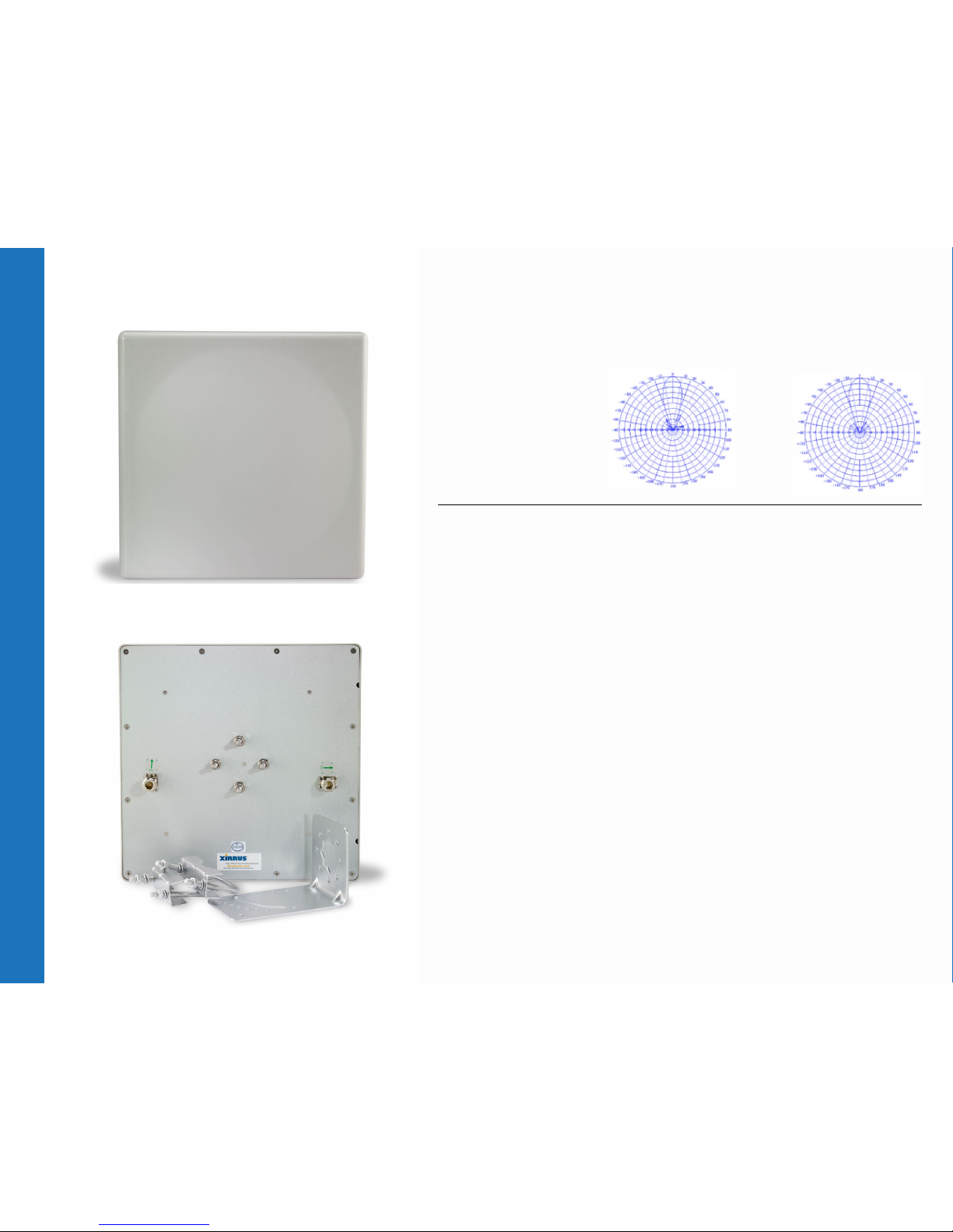
Directional Antennas
DESCRIPTION 15° SINGLE BAND 5GHz 2x2 PANEL ANTENNA
Gain Patterns Vertical Gain Pattern
Horizontal Gain Pattern
Frequency Range (GHz) 5.15-5.85
Impedance 50 ohms
VSWR (50 ohms) ≤1.8
Peak Gain, dBi (5GHz) 17+/- 1
Polarization V/ H
Half-Power Beamwidth Az (H)
17°
Half-Power Beamwidth El (V)
17°
Maximum Power 20W
Connector N-Female x 2
Dimensions 10.3in x 10.3in x 1.4in
Weight 2.5lbs
Operating Temp -40° C to +55° C
Mounting Options Pole Mount included (pole outer diameter 1.6-2”)
Cable Specs
XR-520H, XR-2425H
XH2-120
LMR-195 male RP-TNC to male N Connector, 10’ length
(ANT-CAB-195-10-MM)
LMR-195 male N connectors at both ends, 10’ length
(ANT-CAB-195-10-MM-02)
Extension Cable LMR-400 male N to female N, 10’ length
(ANT-CAB-400-10-MF)
What to order
(per radio)
For use with XR-520H
and XR-2425H:
•1 ANT-DIR15-2x2-XXX-01
• 2 ANT-CAB-195-10-MM
For use with XH2-120:
• 1 ANT-DIR15-2X2-XXX-01
• 2 ANT-CAB-195-10-MM-02
15° Antenna for 5 GHz band (ANT-DIR15-2x2-5.0G-01)
Antenna
Front
Antenna / Connectors
15° Antenna for 5 GHz band (ANT-DIR15-2x2-5.0G-01)
Page 6

Directional Antennas
DESCRIPTION 30° DUAL BAND 2x2 PANEL ANTENNA
Gain Patterns Vertical Gain Pattern
Horizontal Gain Pattern
Frequency Range (GHz) 2.4– 2.5 5.15-5.825
Impedance 50 ohms
VSWR (50 ohms) 2.0: 1 max. typ.
Peak Gain, dBi (2.4 and 5GHz) 11.7-13.5 12.5-14.0
Polarization 2 x +/– 45, V 2 x +/– 45, V
3dB Beamwidth Az (H) 35° +/- 5
3dB Beamwidth El (V) 35° +/- 5
Maximum Power 10 W max.
Connector N-Female x 2 N-Female x 2
Dimensions 16.5in x 9.4in x 1.4 in
Weight 3.75lbs
Operating Temp -40° C to +55° C
Mounting Options Pole Mount included
Cable Specs
XR-520H, XR-2425H
XH2-120
LMR-195 male RP-TNC to male N Connector, 10’ length
(ANT-CAB-195-10-MM)
LMR-195 male N connectors at both ends, 10’ length
(ANT-CAB-195-10-MM-02)
Extension Cable LMR-400 male N to female N, 10’ length
(ANT-CAB-400-10-MF)
What to order
(per radio)*
For use with XR-520H
and XR-2425H:
• 1 ANT-DIR30-2x2-01
• 2 ANT-CAB-195-10-MM
For use with XH2-120:
• 1 ANT-DIR30-2x2-01
• 2 ANT-CAB-195-10-MM-02
30° Antenna (ANT-DIR30-2x2-01)
Antenna
Front
Antenna / Connectors
30° Antenna (ANT-DIR30-2x2-01)
* Each antenna can be connected simultaneously to 2 radios on different bands (2.4GHz and 5GHz) with two additional cables. Additional antennas and cables are
required to connect multiple radios on the same band.
Page 7
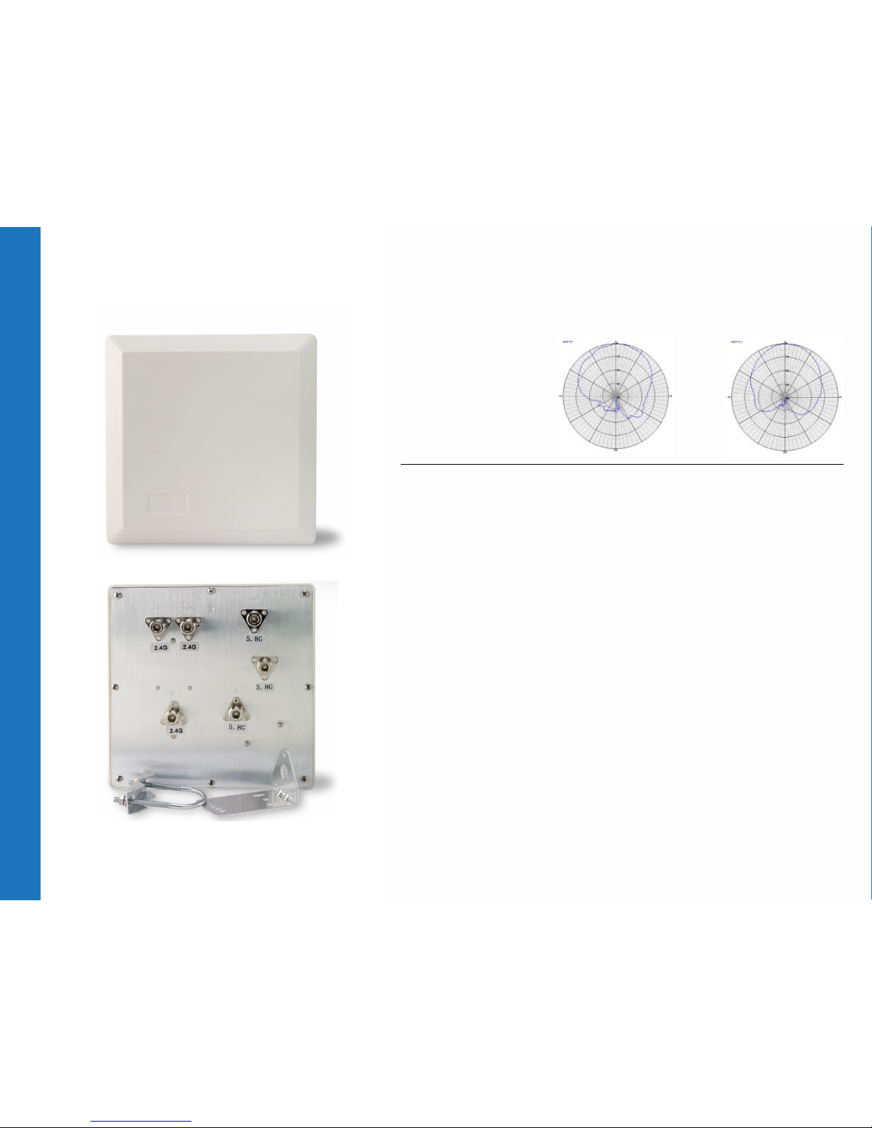
Directional Antennas
DESCRIPTION 60° DUAL BAND 2x2 PANEL ANTENNA
Gain Patterns Vertical Gain Pattern
Horizontal Gain Pattern
Frequency Range (GHz) 2.4– 2.48 5.15-5.850
Impedance 50 ohms
VSWR (50 ohms) 2.0:1 max. typ.
Peak Gain, dBi (2.4 and 5GHz) 7-10 8.5-9.5
Polarization 2 x +/– 45, V 2 x +/– 45, V
3dB Beamwidth Az (H) 65° +/- 5
3dB Beamwidth El (V) 65° +/- 5
Maximum Power 10 W max
Connector N-Female x 3 N-Female x 3
Dimensions 8.6in x 8.6in x 1.18in
Weight 1.49lbs
Operating Temp -40° C to +55° C
Mounting Options Pole Mount included
Cable Specs
XR-520H, XR-2425H
XH2-120
LMR-195 male RP-TNC to male N Connector, 10’ length
(ANT-CAB-195-10-MM)
LMR-195 male N connectors at both ends, 10’ length
(ANT-CAB-195-10-MM-02)
Extension Cable LMR-400 male N to female N, 10’ length
(ANT-CAB-400-10-MF)
What to order
(per radio)*
For use with XR-520H
and XR-2425H:
• 1 ANT-DIR60-2x2-01
• 2 ANT-CAB-195-10-MM
For use with XH2-120:
• 1 ANT-DIR60-2X2-01
• 2 ANT-CAB-195-10-MM-02
60° Antenna (ANT-DIR60-2x2-01)
Antenna
Front
Antenna / Connectors
60° Antenna (ANT-DIR60-2x2-01)
* Each antenna can be connected simultaneously to 2 radios on different bands (2.4GHz and 5GHz) with two additional cables. Additional antennas and cables are
required to connect multiple radios on the same band.
Page 8
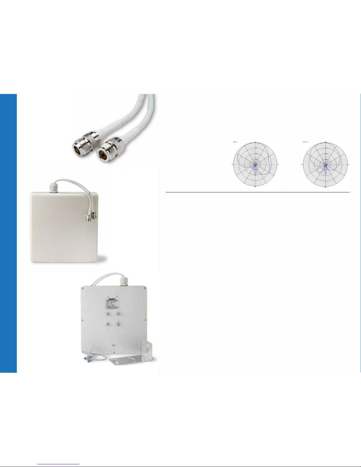
Directional Antennas
DESCRIPTION 90° DUAL BAND 2x2 PANEL ANTENNA
Gain Patterns Vertical Gain Pattern
Horizontal Gain Pattern
Frequency Range (GHz) 2.4– 2.5 5.15-5.85
Impedance 50 ohms
VSWR (50 ohms) 2.0:1 max. typ.
Peak Gain, dBi (2.4 and 5GHz) 4.0 6.5-9.5
Polarization Vertical
3dB Beamwidth Az (H) 90° typ.
3dB Beamwidth El (V) 90° typ.
Maximum Power 10 W max
Connector N-Female x 2*
Dimensions 98in x 9in x 1.96in
Weight 1.7lbs
Operating Temp -40° C to +60° C
Mounting Options Pole Mount
Cable Specs
XR-520H, XR-2425H
XH2-120
LMR-195 male RP-TNC to male N Connector, 10’ length
(ANT-CAB-195-10-MM)
LMR-195 male N connectors at both ends, 10’ length
(ANT-CAB-195-10-MM-02)
What to order
(per radio)
For use with XR-520H
and XR-2425H:
• 1 ANT-DIR90-2x2-01
• 2 ANT-CAB-195-10-MM
For use with XH2-120:
• 1 ANT-DIR90-2x2-01
• 2 ANT-CAB-195-10-MM-02
90° Antenna (ANT-DIR90-2x2-01)
Connectors
Closeup
Antenna
Antenna
Front
Back
90° Antenna (ANT-DIR90-2x2-01)
* Connectors apply for both 2.4 and 5GHz bands.
Page 9

Omni-Directional Antennas
DESCRIPTION
360° DUAL BAND(OMNI DIRECTIONAL)
1X1 ANTENNA (only with XR-520H and XR-2425H)
Gain Patterns Vertical Gain Pattern
Frequency Range (GHz) 2.4– 2.5 5.15-5.825
Impedance 50 ohms
VSWR (50 ohms) 2.0:1 max. typ.
Peak Gain, dBi (2.4 and 5GHz) -1.54-0 -1.7
Polarization 4 x Vertical
3dB Beamwidth Az (H) 360°
3dB Beamwidth El (V) 90° 60°
Maximum Power 10 W max.
Connector RP-TNC-male x 1*
Dimensions 6.1in x 0.5in (Diameter)
Weight 0.05lbs
Operating Temp -10° C to +70° C
Mounting Options direct mount to AP
What to order
(per radio)
For use with XR-520H and XR-2425H:
• 2 ANT-OMNI-1x1-02
“Rubber Duck” Antenna (ANT-OMNI-1x1-02)
Connector
Closeup
Antenna
“Rubber Duck” Antenna (ANT-OMNI-1x1-02)
* Connectors apply for both 2.4 and 5GHz bands.
Page 10
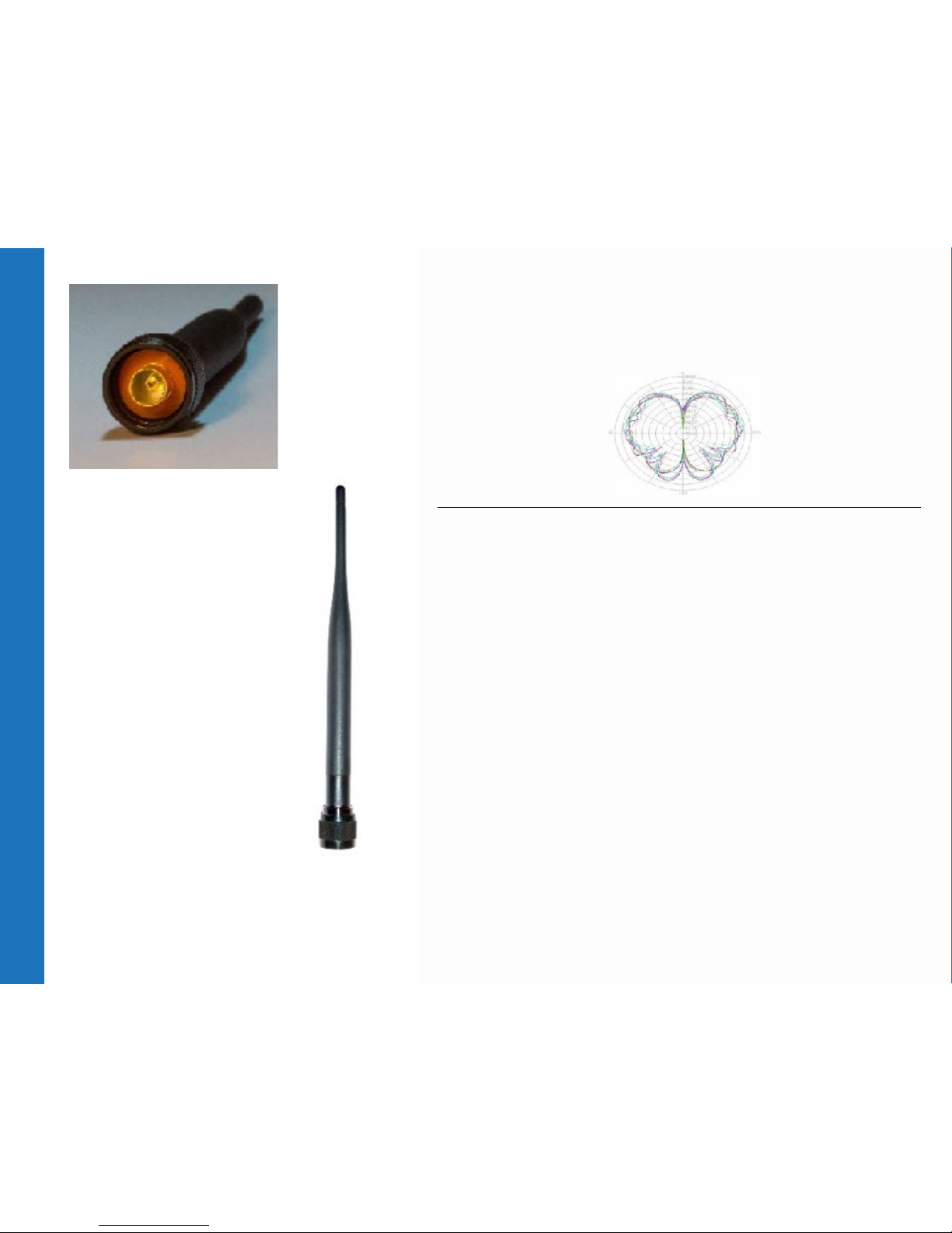
Omni-Directional Antennas
DESCRIPTION
360° DUAL BAND (OMNI DIRECTIONAL)
1x1 ANTENNA (only for the XH2-120)
Gain Patterns Vertical Gain Pattern
Frequency Range (GHz) 2.4– 2.5 5.15-5.35, 5.725-5.85 MHz
Impedance 50 ohms
VSWR (50 ohms) 2.0:1 max. typ.
Peak Gain, dBi (2.4 and 5GHz) 2.0 4.0
Polarization Linear Vertical
3dB Beamwidth Az (H) 360° (Omnidirectional)
3dB Beamwidth El (V) 90° 60°
Maximum Power 10 W max.
Connector N-Male x 1*
Dimensions 7.59in x 0.5in (Diameter)
Weight 0.1lbs
Operating Temp -10° C to +70° C
Mounting Options direct mount to AP
What to order
(per radio)
For use with XH2-120:
• 2 ANT-OMNI-1x1-03
“Rubber Duck”Antenna (ANT-OMNI-1X1-03)
Connector
Closeup
Antenna
“Rubber Duck” Antenna (ANT-OMNI-1x1-03)
* Connectors apply for both 2.4 and 5GHz bands.
Page 11

Omni-Directional Antennas
DESCRIPTION
360° DUAL BAND (OMNI DIRECTIONAL)
2x2 ANTENNA (only for XR-520H and XR-2425H)
Gain Patterns Vertical Gain Pattern
Frequency Range (GHz) 2.4– 2.5 5.15-5.825
Impedance 50 ohms
VSWR (50 ohms) 2.0:1 max. typ.
Peak Gain, dBi (2.4 and 5GHz) 2.3 5
Polarization 4 x V(Linear, Vertical)
3dB Beamwidth Az (H) 360°
3dB Beamwidth El (V) 60°
Maximum Power 10 W
Connector RP-TNC male x 2 RP-TNC male x 2
Dimensions 8.6in x 6.3in (Diameter)
Weight 3lbs
Operating Temp -30° C to +70° C
Ingress Protection IP-54
Mounting Options
1.5” stud mount
Universal wall and mast mountable with included articulating mount. All
tools and hardware included. Mounts to mast up to 1-1/2” in diameter.
Ceiling mountable to 1” thick ceiling tile with jam nut. Also includes rubber
washer for mounting to smooth surfaces such as NEMA enclosures.
What to order
(per radio)*
For use with XR-520H and
XR-2425H:
•1 ANT-OMNI-2x2-02
2x2 Omni Antenna (ANT-OMNI-2x2-02)
Connectors
Closeup
Antenna
Mounts
2x2 Omni Antenna (ANT-OMNI-2x2-02)
* Each antenna can be connected simultaneously to 2 radios on different bands (2.4GHz and 5GHz). Additional antennas and cables are required to connect
multiple radios on the same band.
Page 12

Omni-Directional Antennas
DESCRIPTION
360° DUAL BAND (OMNI DIRECTIONAL)
2x2 ANTENNA (only for XH2-120)
Gain Patterns Vertical Gain Pattern
Frequency Range (GHz) 2.4– 2.5 5.15-5.85
Impedance 50 ohms
VSWR (50 ohms) 1.7 max. typ. 2.0 max. typ.
Peak Gain, dBi (2.4 and 5GHz) 2.3 3.5
Polarization 4 x Vertical
3dB Beamwidth Az (H) 360° 360°
3dB Beamwidth El (V) 60° 50°
Maximum Power 50 W
Connector N-Female x 2 N-Female x 2
Dimensions 7.87in X 4.44in (Diameter)
Weight 1.43lbs
Operating Temp -40° C to + 55° C
Rated Wind Velocity 36.9 (m/s) 82.5 mph
Mounting Options Pole mount: 40-70mm OD, 1.6-2.75in OD
Cable Specs
XH2-120
LMR-195 male N connectors at both ends, 10’ length
(ANT-CAB-195-10-MM-02)
Extension Cable LMR-400 male N to female N, 10’ length
(ANT-CAB-400-10-MF)
What to order
(per radio)*
For use with XH2-120:
• 1 ANT-OMNI-2x2-03
• 2 ANT-CAB-195-10-MM-02
2x2 Omni Antenna (ANT-OMNI-2x2-03)
Antenna
2x2 Omni Antenna (ANT-OMNI-2x2-03)
* Each antenna can be connected simultaneously to 2 radios on different bands (2.4GHz and 5GHz) with two additional cables. Additional antennas and cables are
required to connect multiple radios on the same band.
Page 13

Design Considerations and Reference Use Cases
There are several factors that impact the performance of a
Wireless LAN and must be kept in mind while designing for a
deployment. Some of the key considerations are as follows:
Mobility of the Application: The mobility of the clients that will be
connecting to the Array through the antenna system is the rst
thing to think about when planning a deployment. An application
that has a lot of mobile users, such as a convention center is best
served by a large number of omnidirectional microcells while a
point-to-point application, which connects two or more stationary
users may be best served by a directional antenna.
Physical Environment: Some of the things to watch for in the
environment where the WLAN deployment is planned include:
• Building construction – The density of the materials used in a
building’s construction determines the number of walls the RF
signal can pass through and still maintain adequate coverage.
The following is a good reference but the actual effect of the
walls on RF must be tested through a site survey. A thick metal
wall, such as an elevator reects signals, resulting in poor
penetration of the signal and low quality of reception on the
other side. Solid walls and oors and precast concrete walls can
limit signal penetration to one or two walls without degrading
coverage, but, this can vary greatly depending on the amount
of steel reinforcing within the concrete. Concrete and concrete
block walls will likely limit signal penetration to three or four
walls. Wood or dry wall will typically allow for adequate signal
penetration through ve or six walls. Paper and Vinyl walls have
little effect on signal penetration.
• Ceiling height
• Internal obstructions – Product inventory and racking are factors
to consider in a indoor environment, such as a warehouse.
In outdoor environments, many objects can affect antenna
patterns, including trees, vehicles and buildings.
• Available mounting locations.
In addition, consideration some consideration should also be
given to aesthetic appearance.
Access to network connections (minimize Antenna cable runs):
Cabling between the Array or AP and the antenna introduces
losses in the system, therefore the length of this cable run must be
minimized as much as possible.
Warehouse Use Case: In most cases, these installations require
a large coverage area. Experience has shown that multiple
omnidirectional antennas (such as ANT-OMNI-1x1-01 or
ANTOMNI-2x2-02) mounted at 20 or 25 feet typically provide the
best coverage. Of course this is also affected by the height of
the racking, the material in the racks and your ability to locate
the antenna at this height. The antenna should be placed in the
center of the desired coverage cell an in an open area for best
performance. In cases where the ceiling is too high and the Array
or AP will be located against a wall, a directional antenna may
be used.
Small Ofce or Small Retail Store: An omnidirectional dipole
antenna (such as ANT-OMNI-1x1-01 or ANT-OMNI-2x2-02) will
provide best coverage for type of scenario.
Enterprise or Large Retail Store: In most such deployments, there
is a need for a fairly large coverage area and a combination of
omnidirectional and directional antennas must be used. Omnidirectional
antennas located just below the ceiling girders or just
below the drop ceiling and directional antennas located at the
corners. Also, for areas that are long and narrow – such as long
store aisles – a directional antenna at one end may provide better
coverage. Keep in mind that the radiation angle of the antenna
will also affect the coverage area.
Apartment Complex Backhaul (Point-to-Point): For an application
where last mile connectivity is being provided using Wi-Fi
(such as apartment complexes or senior living complexes that
may not have traditional wiring infrastructure), point-to-point
connections are common. When establishing point to point
connections in outdoor environments, the distance, obstructions
Page 14

and antenna locations must be considered. For short distances
(several hundred feet), a standard dipole antenna may be used.
For very large distances (1/2 mile or more) high-gain directional
antennas must be used. The antennas must be installed as high as
possible, above obstructions such as trees, buildings and similar.
If directional antennas are used, they must be aligned so that their
main radiated power lobes are directed at each other.
Support & Maintenance
Xirrus is committed to the success of our customers and
provides warranties and support options to best t your needs..
For further information on the Xirrus hardware warranties,
software support and premium support offerings visit:
http://www.xirrus.com/support/
About Xirrus
To organizations who depend on wireless access to transform
their business, Xirrus is the wireless network solution provider
that provides the world’s most powerful, scalable, and trusted
solutions. Through product invention and system design,
commitment to customer success, and the industry’s best
price performance, Xirrus gives you condence that your
wireless network performs under even the most demanding
circumstances. Xirrus is a privately held company headquartered
in Thousand Oaks, CA.
IB H igh erE du 1115 -00 1
©2015 Xirrus, Inc. All tradema rks and registered t rademarks are the p roperty of
their resp ective owners. T he information cont ained herein is subj ect to change
without no tice and is provided “ as is” without warr anty of any kind. Xir rus shall not
be liable for te chnical or editor ial errors or omis sions contained he rein.
World Headquarters
Xirrus, Inc.
2101 Corporate Center Drive
Thousand Oaks, CA 91320
Tel: +1 (805) 262-1600
Silicon Valley Headquarters
Xirrus, Inc.
440 N. Wolfe Road
Sunnyvale, CA 94085
Tel: +1 (805) 262-1600
European Headquarters
Xirrus, Inc.
400 Thames Valley Park Drive
Thames Valley Park, Berkshire RG6 1PT
Tel: +44 (0) 118-963-7684
 Loading...