


XT6264 User Guide
P a g e 1 | 14
CONFIDENTIAL AND PROPRIETARY
Disclosure, storage and use subject to non-disclosure agreement
XT6264 User Guide
Revised July 19, 2019
This user guide contains supplemental information about the XT6264.

XT6264 User Guide
P a g e 2 | 14
CONFIDENTIAL AND PROPRIETARY
Disclosure, storage and use subject to non-disclosure agreement
1 CONTENTS
1 Contents ................................................................................................................................................ 2
2 Installation Procedure ........................................................................................................................... 3
2.1 Terminology .................................................................................................................................. 3
2.2 Installation .................................................................................................................................... 3
2.3 Testing After Installation ............................................................................................................... 7
3 LED Behavior ......................................................................................................................................... 8
3.1 Test Mode ..................................................................................................................................... 8
3.1.1 LED Color Table ..................................................................................................................... 8
3.1.2 RCD3 LED Status Indication Mode ........................................................................................ 8
3.2 Install Mode ................................................................................................................................ 11
3.2.1 Entering Install Mode .......................................................................................................... 11
3.2.2 Install Mode Operation and Status ..................................................................................... 11
3.2.3 Exiting Install Mode ............................................................................................................. 11
4 Regulatory Statements ....................................................................................................................... 12
4.1 FCC: ............................................................................................................................................. 12
4.2 Radiofrequency radiation exposure Information: ...................................................................... 12
4.3 IC ................................................................................................................................................. 12
XT6264 User Guide
P a g e 3 | 14
CONFIDENTIAL AND PROPRIETARY
Disclosure, storage and use subject to non-disclosure agreement
2 INSTALLATION PROCEDURE
2.1 TERMINOLOGY
Term
Description
Unit
Xirgo XT6264
Asset
Customer product that the XT6264 is mounted to.
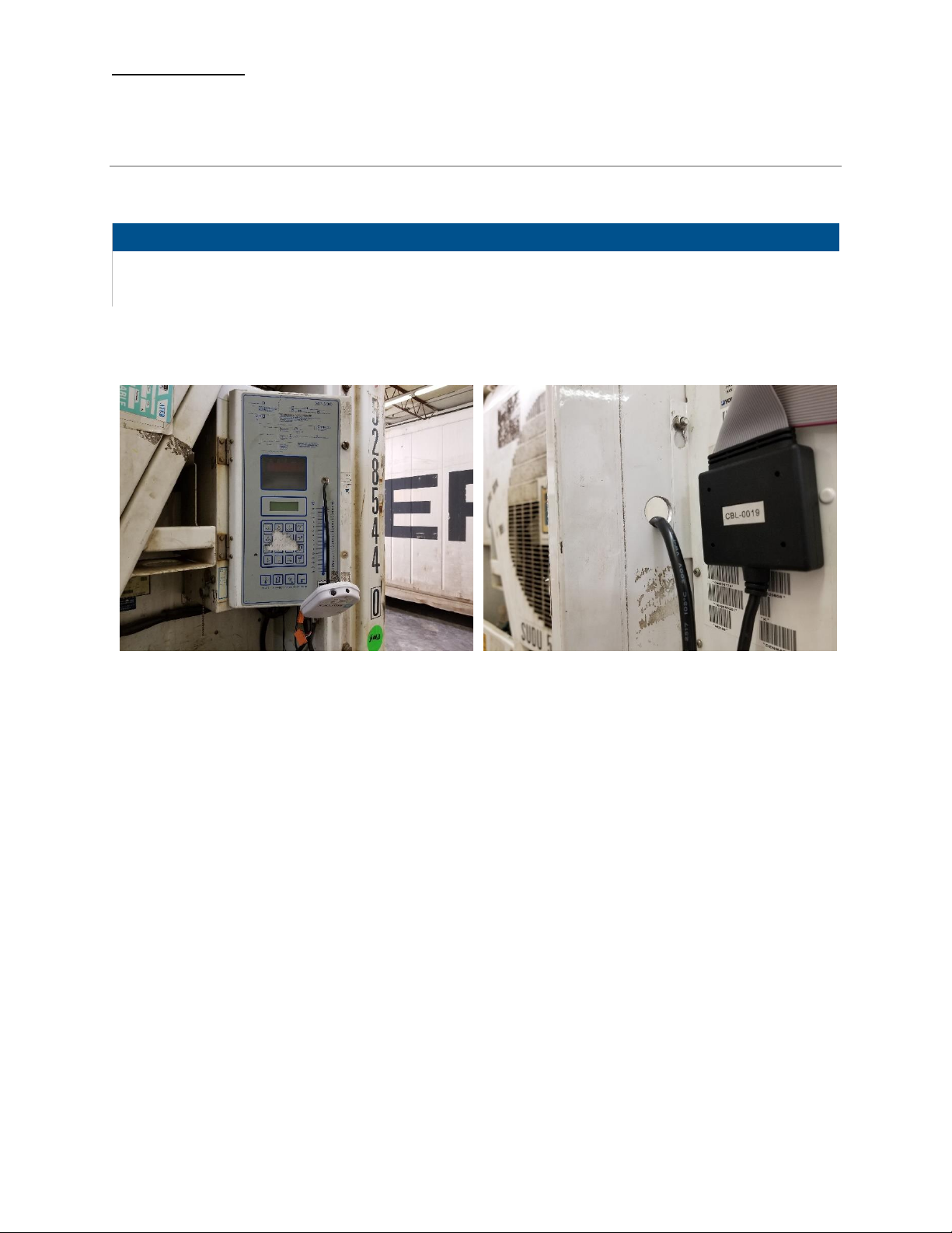
2.2 INSTALLATION
Figure 1: Hole Location
Figure 2: Size of hole – 19mm
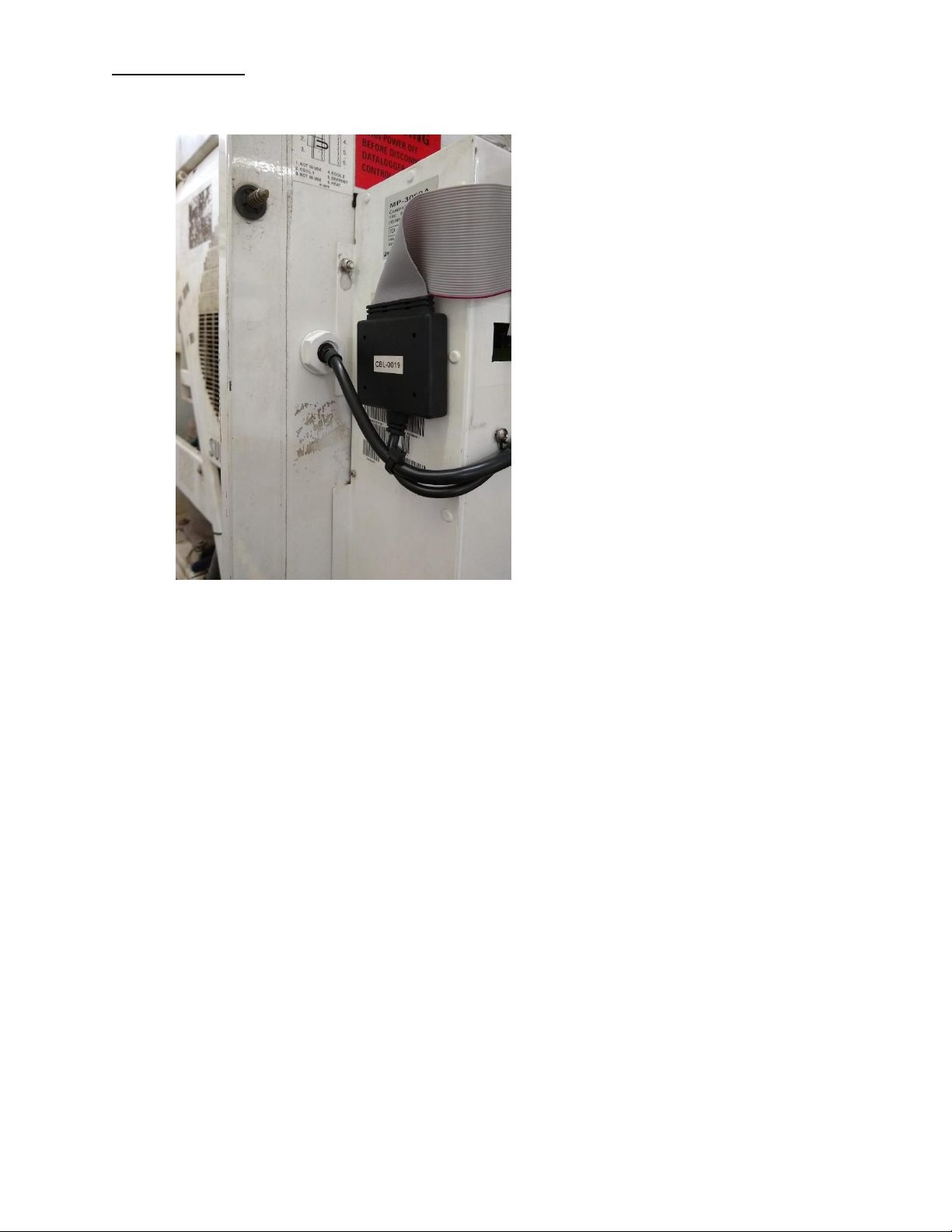
1. Install the unit bracket.
2. Secure the unused high voltage communication connector into unit bracket.
3. Install the unit into the bracket.
a. Push the unit into the bracket
b. Secure the two torx screws
c. Push the ON/OFF switch
4. Connect the 3 and 7 pin connectors to the unit.
5. Connect the unit ribbon harness to the controller.
XT6264 User Guide
P a g e 4 | 14
CONFIDENTIAL AND PROPRIETARY
Disclosure, storage and use subject to non-disclosure agreement
Figure 3: Ribbon Harness
6. Attach the TK bracket to the unit.
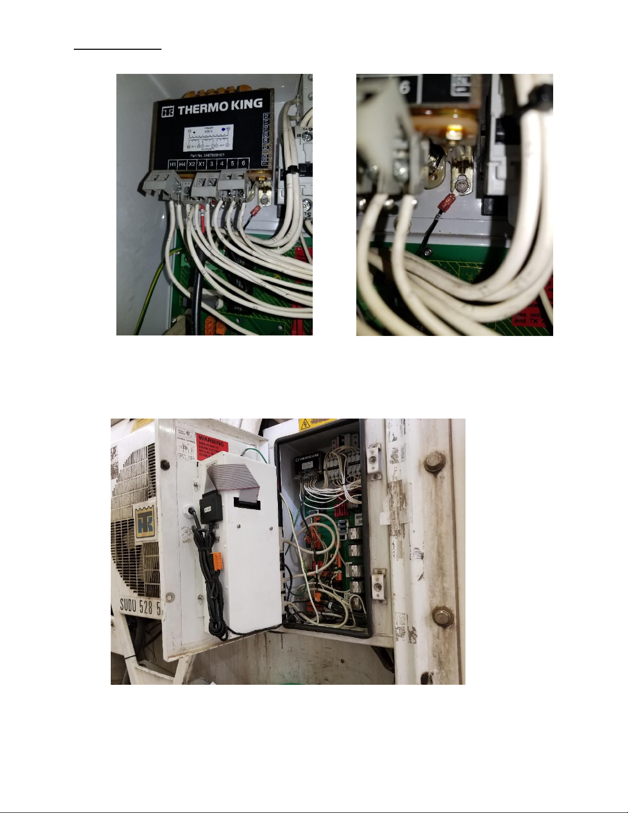
7. Fit the unit with the bracket TK controller and tighten the upper screws.
8. Connect the Power Cable Harness X1 RED wire to the Transformer X1 tap, and X2 BLACK wire
(with ground terminal) to the Controller Chassis.
XT6264 User Guide
P a g e 5 | 14
CONFIDENTIAL AND PROPRIETARY
Disclosure, storage and use subject to non-disclosure agreement
Figure 5: X1 red to X1 tap
Figure 6: X2 Black to ground chassis
9. Connect the 7 pin from the unit ribbon harness to the unit.
10. Bundle the cable by using cable ties and fix them to the unit.
11. Close the asset door. The device should be oriented as pictured below:

XT6264 User Guide
P a g e 6 | 14
CONFIDENTIAL AND PROPRIETARY
Disclosure, storage and use subject to non-disclosure agreement

XT6264 User Guide
P a g e 7 | 14
CONFIDENTIAL AND PROPRIETARY
Disclosure, storage and use subject to non-disclosure agreement
2.3 TESTING AFTER INSTALLATION
1. Connect the power plug to the power source.
2. Put the unit into install mode (ON/OFF button) – see Enter Install Mode for further description.
3. Observe installer LED for green pass – see observe Install LED below for further description.
NOTE: if installer LED fails, refer to the trouble shooting guide and fix the issue.
4. Take the unit out of installer mode.
5. Close the controller door.
NOTE: at this time, installation should be completed.
XT6264 User Guide
P a g e 8 | 14
CONFIDENTIAL AND PROPRIETARY
Disclosure, storage and use subject to non-disclosure agreement
3 LED BEHAVIOR
3.1 TEST MODE
When the device is in Active mode (i.e., not in ship mode or low power sleep mode), a push and release
of the button when the green LEDs start blinking will cause the device to display status using LEDS as
described below. LEDs will stay off in the normal device operation.
NOTES:
• The push and release of the button when blue LEDs start blinking will put the device in INSTALL
mode. The LED behavior in INSTALL mode is covered in Install Mode section.
• If the button remains pushed until blue LEDs go off and then the buttons are released, device
will enter Ship Mode.
• Pushing and releasing the button when the device is in ship mode will wake the device up like in
RCD2 and will not initiate LED status indication mode.
3.1.1 LED Color Table
LED Color
Description
Blue
GPS Status
Green
Cellular Status
Purple
Cellular RAT Status
Yellow
Battery Status
Red
Backend, AC, Reefer, Zigbee, and Bluetooth
3.1.2 RCD3 LED Status Indication Mode
When the device enters install mode, it will display all LED status updates. The LEDs will provide updates
in the following order: Blue, Green, Purple, Yellow, and then Red.
GPS Status (Blue)
• All five LEDs will flash blue for two seconds to indicate the device is providing GPS status.
• From left to right, GPS status is provided with a solid blue LED and the value is held for five
seconds.

XT6264 User Guide
P a g e 9 | 14
CONFIDENTIAL AND PROPRIETARY
Disclosure, storage and use subject to non-disclosure agreement
LED Status
Description
GPS Lock
Left-most LED ON means GPS is locked
GPS Number
Each LED following the left most LED represents three GPS satellites. Satellite
numbers in between groups of three will be rounded up; e.g., four or five satellites in
view will be represented with two LEDs.
No Lock
Left most LED blinking means no lock and no satellite in view
Cellular Status (Green)
• Four LEDs will flash green for two seconds, indicating the device is providing cellular signal
strength. The left most LED will be used to indicate cellular RAT.
• From left to right, LEDs indicate received signal strength value using solid green LEDs and will
hold the value for five seconds.
RSSI Level
LED Number
1
One LED
2
Two LED
3
Three LED
4
Four LED
Cellular RAT Status (Purple)
• All five LEDs will flash purple for two seconds to indicate the device will be providing cellular RAT
status.
• From left to right, the cellular RAT is indicated using solid purple LEDs held for five seconds.
Cellular RAT
LED Number
Connection Failure
Left most LED blinking
2G Registered
One LED
3G Registered
Two LEDs
LTE Registered
Three LEDs

XT6264 User Guide
P a g e 10 | 14
CONFIDENTIAL AND PROPRIETARY
Disclosure, storage and use subject to non-disclosure agreement
Battery Status (Yellow)
• All five yellow LEDs will flash yellow for two seconds to indicate the device will provide battery
status.
• From left to right the backup battery value is indicated using solid yellow LEDs, which are held
for five seconds.
LED
Voltage
Left most LED (blinking)
Volt < 2.9
One LED
2.9 < Volt < 3.2
Two LEDs
3.2 < Volt < 3.5
Three LEDs
3.5 < Volt < 3.8
Four LEDs
3.8 < Volt < 4.0
Five LEDs
4.0 < Volt
Backend, AC, Reefer, Zigbee, and Bluetooth (Red)
• All five LEDs will flash red for two seconds to indicate the device is providing miscellaneous
status.
• LEDs are displayed from left two right and held for five seconds.
LED Position
Description
First
Backend connectivity status: Green if data session active or no messages queued.
Red if messages queued and no data session active.
Second
AC Status: Green if AC applied, Red if no AC.
Third
Reefer Connectivity: Green if last communication with reefer was successful, Red
otherwise.
Fourth
Zigbee Status: Green if device is in network otherwise Red.
Fifth
BLE Status: To be determined.
NOTE: Test mode should now be complete, and all LEDs will turn off.

XT6264 User Guide
P a g e 11 | 14
CONFIDENTIAL AND PROPRIETARY
Disclosure, storage and use subject to non-disclosure agreement
3.2 INSTALL MODE
3.2.1 Entering Install Mode
The device must be active, i.e., either on battery hold off period or external power. This is not applicable
during battery profile wakes (periodic, listen, motion start/stop).
Press and hold the button until the blue LED is blinking; release the button. The device will reboot into
install mode indicated by the fast blinking green LED.
3.2.2 Install Mode Operation and Status
Install mode is a special test mode which does not provide normal operations. Test in progress is
indicated by a fast blinking green LED. At the end of the Install mode test, the following test result status
would be displayed through solid LED indication. LED1 is the left most LED and LED2 is next to LED1 and
so on.
AC Power Connection
• Green LED1: AC power detected
• Red LED1: Failed AC power detection
RS232 physical connection
• Green LED2: Physical RS232 detected
• Red LED2: Failed RS232 detection
Reefer Communication
• Green LED3: Successful communication with controller
• Red LED3: Failed communication with controller
3.2.3 Exiting Install Mode
• Push the button and hold for approximately five seconds any time after install mode status
indication.
• OR, timeout for fifteen minutes from the start of LED status indication.
NOTE: either of the above will cause a reboot of the device to the normal operation mode.

XT6264 User Guide
P a g e 12 | 14
CONFIDENTIAL AND PROPRIETARY
Disclosure, storage and use subject to non-disclosure agreement
4 REGULATORY STATEMENTS
4.1 FCC:
This device complies with Part 15 of the FCC Rules.
Operation is subject to the following two conditions:
(1) this device may not cause harmful interference, and
(2) this device must accept any interference received, including interference that may cause
Changes or modifications made to this equipment not expressly approved by Xirgo Technology may void
the FCC authorization to operate this equipment.
NOTE: This equipment has been tested and found to comply with the limits for a Class B digital device,
pursuant to Part 15 of the FCC Rules. These limits are designed to provide reasonable protection
against harmful interference in a residential installation. This equipment generates, uses and can
radiate radio frequency energy and, if not installed and used in accordance with the instructions,
may cause harmful interference to radio communications. However, there is no guarantee that
interference will not occur in a particular installation. If this equipment does cause harmful
interference to radio or television reception, which can be determined by turning the equipment
off and on, the user is encouraged to try to correct the interference by one or more of the following
measures:
• Reorient or relocate the receiving antenna.
• Increase the separation between the equipment and receiver.
• Connect the equipment into an outlet on a circuit different from that to which the receiver is
connected.
• Consult the dealer or an experienced radio/TV technician for help.
4.2 RADIOFREQUENCY RADIATION EXPOSURE INFORMATION:
This equipment complies with FCC radiation exposure limits set forth for an uncontrolled environment.
This equipment should be installed and operated with minimum distance of 20 cm between the radiator
and your body. This transmitter must not be co-located or operating in conjunction with any other
antenna or transmitter.
4.3 INDUSTRY CANADA
This device complies with Industry Canada license-exempt RSS standard(s). Operation is subject to the
following two conditions:
(1) this device may not cause interference, and
(2) this device must accept any interference, including interference that may cause undesired
operation of the device.
Le présent appareil est conforme aux CNR d'Industrie Canada applicables aux appareils radio
exempts de licence. L'exploitation est autorisée aux deux conditions suivantes :

XT6264 User Guide
P a g e 13 | 14
CONFIDENTIAL AND PROPRIETARY
Disclosure, storage and use subject to non-disclosure agreement
(1) l'appareil ne doit pas produire de brouillage, et
(2) l'utilisateur de l'appareil doit accepter tout brouillage radioélectrique subi, même si
le brouillage est susceptible d'en compromettre le onctionnement.
Under Industry Canada regulations, this radio transmitter may only operate using an antenna of a type
and maximum (or lesser) gain approved for the transmitter by Industry Canada. To reduce potential
radio interference to other users, the antenna type and its gain should be so chosen that the equivalent
isotropically radiated power (e.i.r.p.) is not more than that necessary for successful communication.
Conformément à la réglementation d'Industrie Canada, le présent émetteur radio peut fonctionner avec
une antenne d'un type et d'un gain maximal (ou inférieur) approuvé pour l'émetteur par Industrie
Canada. Dans le but de réduire les risques de brouillage radioélectrique à l'intention des autres
utilisateurs, il faut choisir le type d'antenne et son gain de sorte que la puissance isotrope rayonnée
équivalente (p.i.r.e.) ne dépasse pas l'intensité nécessaire à l'établissement d'une communication
satisfaisante.
This radio transmitter (IC: 10281A-XT6264, Model Number: XT6264) has been approved by Industry
Canada to operate with the antenna types listed below with the maximum permissible gain and
required antenna impedance for each antenna type indicated. Antenna types not included in this
list, having a gain greater than the maximum gain indicated for that type, are strictly prohibited for
use with this device.
Cet émetteur radio (identifier le périphérique par numéro de certification, ou le numéro de modèle si
Catégorie II) a été approuvé par Industrie Canada pour fonctionner avec les types d'antennes
énumérées ci-dessous avec le gain maximal admissible et l'impédance d'antenne requise pour chaque
antenne type indiqué. Types d'antennes ne figurent pas dans cette liste, ayant un gain supérieur au
maximum gagner indiqué pour ce type, sont strictement interdites pour une utilisation avec cet
appareil.
GNSS Antenna Specifications
Parameter
Description
Band Support
GPS: 1575.42 MHz ± 1.02 MHz
GLONASS: 1601.72 MHz ± 8.76625 MHz
Peak Realized Gain
GPS: ≤ 3.0 dBi
GLONASS: ≤ 3.0 dBi
2.45 GHz Antenna Specifications
Parameter
Description
Frequency (GHz)
2.4 - 2.48
Peak Gain (dBi)
1.5 dBi
1
Efficiency measured on Johanson’s evaluation board PN 2450AT18D0100-EB1SMA

XT6264 User Guide
P a g e 14 | 14
CONFIDENTIAL AND PROPRIETARY
Disclosure, storage and use subject to non-disclosure agreement
2G/GSM LTE Antenna Specifications
Parameter
Band 5
Band 2
Channel
Uplink
Downlink
Uplink
Downlink
Frequency (MHz)
880-915
925-960
1710.2-1785.2
1804.8-1879.8
Peak Gain (dBi)
<2
<-5.9
<3.7
<2.8
3G/UMTS LTE Antenna Specifications
Parameter
Band 5
Band 2
Band 8
Band 1
Channel
Uplink
Downlink
Uplink
Downlink
Uplink
Downlink
Uplink
Downlink
Frequency (MHz)
824-849
869-894
1850-1910
1930-1990
880-915
925-960
1920-1980
2110-2170
Peak Gain (dBi)
5.0
2.6
4.0
4.1
<2
<-5.9
<2.8
<1.4
4G LTE Antenna Specifications
Parameter
Band 12
Band 5
Band 4
Band 2
Channel
Uplink
Downlink
Uplink
Downlink
Uplink
Downlink
Uplink
Downlink
Frequency (MHz)
699-716
729-746
824-849
869-894
1710-1755
2110-2155
1850-1910
1930-1990
Peak Gain (dBi)
3.5
4.5
5.0
2.6
3.9
3.5
4.0
4.1
4G LTE Antenna Specifications (continued…)
Parameter
Band 28
Band 20
Band 8
Band 3
Channel
Uplink
Downlink
Uplink
Downlink
Uplink
Downlink
Uplink
Downlink
Frequency (MHz)
703-748
758-803
832-862
791-821
880-915
925-960
1710-1785
1805-1880
Peak Gain (dBi)
<2.3
<2.44
<1.3
<2
<2
<-5.9
<3.7
<2.8
4G LTE Antenna Specifications (continued…)
Parameter
Band 1
Band 40
Band 7
Band 38
Channel
Uplink
Downlink
Uplink
Downlink
Uplink
Downlink
Uplink
Downlink
Frequency (MHz)
1920-1980
2110-2170
2300-2400
2300-2400
2500-2570
2620-2690
2570-2620
2570-2620
Peak Gain (dBi)
<2.8
<1.4
<1.4
<1.4
<1.75
<1.3
<1.2
<1.2
The DOC (Declaration of Conformity) is either included in the packaging or can be found at the
following link: www.xirgo.com
 Loading...