

Page 1

Intel® PRO/Wireless 5000
LAN Products
Quick Installation Guide
Page 2

Copyright © 2001, Intel Corporation. All rights reserved.
Intel Corporation assumes no responsibility for errors or omissions in this
document. Nor does Intel make any commitment to update the information
contained herein.
Intel is a registered trademark of Intel Corporation. Other product and
corporate names may be trademarks of other companies and are used only
for explanation and to the owners' benefit, without intent to infringe.
801-0311-001A November 2001
2
Page 3

Table of Contents
Installing the Access Point..........................4
Installing the CardBus Adapter.................11
Installing the PCI Adapter.......................... 14
3
Page 4

Intel® PRO/Wireless 5000 LAN Products
User Documentation
In addition to this Quick Installation Guide, Intel provides extensive online
documentation for the PRO/Wireless 5000 LAN product line on the Intel CDROM in HTML format.
Note: The Intel CD-ROM may contain documentation for other Intel products
in addition to the PRO/Wireless 5000 LAN Products. Please disregard the
documentation for other products.
All documentation for the PRO/Wireless 5000 LAN Products is accessible by
clicking a button on the autorun menu screen displayed when the Intel CDROM is inserted into the computer (if this screen does not appear, run
autorun.exe from the root directory of the Intel CD-ROM). Disregard any
documentation on the CD-ROM that is not accessible through this autorun
menu screen.
Installing the Access Point
Package Contents
Intel® PRO/Wireless 5000 LAN Access Point (model WSAP5000)
x
Mounting hardware
x
Power supply and power cord
x
CD-ROM containing software and online documentation
x
Quick Installation Guide (this manual)
x
Installation Options and Requirements
(Recommended)
x
client workstation connected to the access point directly or connected to
the wired LAN to which the access point is connected. Initial setup and
configuration must be done over a wired connection, but subsequent
changes can be made over a wireless connection.
(Optional)
x
address to the access point over the wired network. You can configure
the access point to use DHCP to get its IP address. See Using DHCP
on page 8.
4
To set up and configure the access point, use a wired
Use DHCP server support for automatic assignment of an IP
Page 5

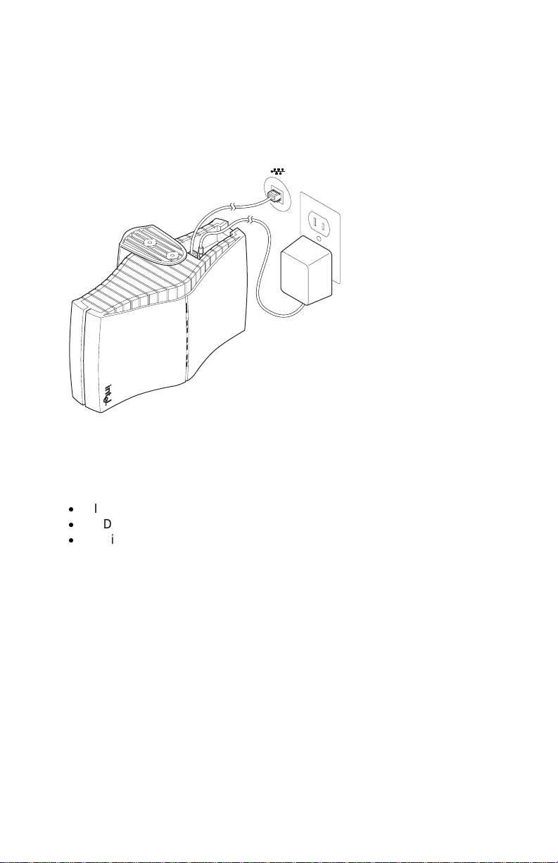
Connect and Power Up the Access Point
Connect the Access Point to the Wired Network
Plug an RJ-45 Category 5 Ethernet cable into the RJ-45 connector on
x
the access point and into a 10/100 Ethernet wall connector or hub.
Connect the Access Point to an AC Power Source
Plug the power adapter into a wall outlet.
x
Plug the power adapter cable into the socket on the bottom of the
x
access point.
LED Indicators
Once the access point is connected to a wired network and is powered on,
check the LED indicators to verify that the unit is functioning correctly. If the
access point fails to initialize, restart it by disconnecting and reconnecting
power.
The "Ready" LED at the bottom of the row of LEDs should be lit.
x
If the access point is connected to a LAN through an Ethernet cable, the
x
"Wired Link" LED should be lit (green for 10 Mbps, orange for 100
Mbps) and the "Wired network activity" LED should be blinking.
If the access point is communicating with a wireless adapter, the
x
"Wireless radio activity" LED should be flashing.
Viewed top to bottom, the LED indicators on the access point have the
following functions.
Wired link
Wired network
activity
Wireless radio
association
Wireless radio
activity
Wireless radio
association
Wireless radio
activity
Ready
Green for 10 Mbps wired network speed, orange for
100 Mbps.
Yellow blinking shows activity.
Green will be ON if a client is associated to the
access point and OFF if not.
Yellow flashes steadily if no adapter associated, and
more rapidly when transferring data.
Future use.
Future use.
Green. This indicator will stay illuminated after the
access point has completed the initialization
sequence.
5
Page 6

Configuring the Access Point for the First Time
1. Set up a portable or desktop computer as a configuration workstation
from which to view the browser-based Configuration Management
System used to configure the access point.
2. Connect the configuration workstation to the access point either directly
(using a crossover RJ-45 cable) or through a hub or switch (using a
standard RJ-45 cable).
3. The configuration workstation must be running Microsoft Windows® XP,
2000, Me, or 98, and one of the following web browsers: Microsoft
Internet Explorer version 5.50 or Netscape Navigator version 4.78 or 5.x
4. Set up the configuration workstation initially with an IP address
compatible with the default IP address and defau lt subnet of the
access point. For example, based on the access point default IP
address 192.0.2.1 and default subnet 255.255.0.0, the client workstation
could be set to 192.0.2.2, 192.0.2.3, or a similar address not in use by
another device.
5. Once the workstation has been configured as just described, type the
default access point IP address as a URL in the browser address field:
http://192.0.2.1.
6. To access the Express Setup pages, type a user name and a password.
The default for both is: Intel. The password is case-sensitive: capital "I,"
lower case "ntel."
7. Use Express Setup to configure the access point with a new IP
address, subnet, and other settings suitable for the network to which
it will be permanently connected (see table on page 7).
8. Click Apply first, then click Restart AP. After the access point has
restarted, connect it to the required network.
9. Once the access point has been configured and connected to the
network, the configuration interface can be viewed from any workstation
on the same network segment or subnet. Open a compatible browser
and type the actual IP address of the access point as a URL in the
address field.
Note: To view configuration, function or option changes on the browser
pages, turn off the browser's caching function.
For Netscape, from the menu bar select Edit, Properties, Advanced,
x
Cache, the select Document in cache is compared to document on
network: Every time.
For Internet Explorer, from the menu bar select View, Internet Options,
x
Temporary Internet files, Settings, then select Check for newer versions
of stored pages: Every visit to the page.
6
Page 7

Settings for First Time Configuration (Express Setup)
For complete coverage of access point settings see the access point Help
file or the online User’s Guide.
Setting
Default
IP
Address
System
Name
Default
Subnet
Mask
Default
Gateway
DHCP
Help
URL
SSID
11A
Description
The default IP address is 192.0.2.1. An IP address is not
dynamically assigned to the access point under its default
configuration. Use the default address initially, then change it
to a valid address for the network to which the access point
will be connected. For dynamic address assignment, see the
section Using DHCP.
User-defined name for the access point. Any combination of
letters and numbers from 1 to 32 characters. Default is the
model number of the access point.
The default Subnet Mask is 255.255.0.0 if DHCP usage is
Disabled or DHCP service is not available. Change this to a
valid subnet mask for the network to which the access point
will be connected.
There is no default gateway initially configured. Use a valid
gateway address for the network to which the access point
will be connected. If no valid gateway is defined on your
network, use the default gateway 0.0.0.0. For gateway
assignment via DHCP, see the section Using DHCP.
The Dynamic Host Configuration Protocol (DHCP)
dynamically assigns IP addresses on a network with a DHCP
server. DHCP default setting for the PRO/Wireless 5000 LAN
Access Point is Disabled. To change this to Enabled and
install the access point on a network using DHCP support,
see Using DHCP.
Location of the Help files accessible by clicking the Help
button on a screen in the access point Configuration
Management System. See the online User’s Guide for
information.
Service Set Identifier (also called Network Name, Network ID,
ESSID) identifies the network to which the access point is
connected. All access points and client workstations on the
same wireless LAN must have the same SSID, which can be
any combination of letters and numbers up to 32 characters.
Default for Intel PRO/Wireless 5000 LAN devices is "101."
The default SSID is intended only for preliminary setups and
connections; it should usually be changed to a descriptive
name for the wireless LAN network in question.
7
Page 8

Using DHCP (Optional)
The Intel PRO/Wireless 5000 LAN Access Point can be configured to use
DHCP to get its IP address, subnet mask, and default gateway:
1. Access the Express Setup page in the browser-based Configuration
Management System as described in Steps 1-6 under Confi g uring the
Access Point for the First Time on page 6.
2. Change the DHCP setting from Disabled to Enabled on the Express
Setup page or the Configuration page. Save the new settings by clicking
Apply, then click Restart AP. After the restart, connect the access point
to the network to which it will be permanently connected.
3. The next time the access point is restarted after DHCP has been
enabled, it will attempt to get its IP address, subnet mask, and default
gateway from the DHCP server. If no server is available, the access
point will use the Default IP Address and Default Subnet Mask settings.
4. When the access point used DHCP to obtain its IP address, you will
have to determine the IP address before you can access the
configuration pages. There are several strategies you can use for this,
based on the MAC address assigned to the access point:
Before connecting the "DHCP Enabled" access point to a DHCP
x
network, ask your network administrator to reserve an IP address,
based on the MAC address for the access point, in the DHCP
"lease table." This will allow the DHCP server to recognize the
access point when it is connected to the network and assign it a
known IP address based on the MAC address.
You can also connect a "DHCP Enabled" access point to a DHCP
x
network immediately, without reserving the MAC address before
connection. In this case an address will be assigned automatically,
but you will have to request the address from your network
administrator, who will obtain it from the DHCP "lease table."
You can also use the Intel Access Point Administration Tool AP
x
Discovery to find the access point and display its IP address. See
the online User’s Guide for details.
Restore Factory Defaults
The access point has a Reset button that can be used to perform a hardware
reset or to restore the access point's factory default settings.
The Reset button is located in a pinhole on the bottom of the access point.
Insert the end of an unbent paper clip into the hole and apply pressure as
follows:
Press and release the Reset button quickly to perform a hardware reset.
x
Press and hold the Reset button until the “Ready” LED flashes quickly 3
x
times. This will restore all access point parameters to factory default
settings, including default user name, password, and IP address.
8
Page 9

Access Point Factory Default Settings
System name
IP address
Subnet mask
Default gateway
User
Password
SSID 11A
WEP 11A
WSAP5000 (or the model number of your access
point)
192.0.2.1
255.255.0.0
None
Intel (case sensitive)
Intel (case sensitive)
101
Disabled
Setting Up a Wireless LAN
For detailed information on site survey, setup, positioning, and testing of
access points on your wireless LAN, see the online User’s Guides on the
Intel CD-ROM. On the autorun menu screen (which displays when you load
the CD-ROM or run autorun.exe from the CD-ROM), select “Access Point
Manuals,” “Main Contents,” and “Administrator’s Guide.”
Mount the Access Point
Position each Access point using the following guidelines and illustrations.
For best throughput and range, install the Access Point as high as practical.
Desktop or Table Top Location
Set the access point on a flat surface such as a table or desk. If the access
point is positioned on a desk or table, the antenna should be on top (as
shown above).
9
Page 10

WARNING!!
To comply with the FCC and ANSI C95.1 RF exposure limits, it is recommended for the
Accesspoint, or a PCI Adapter card, installed in a desktop computer, that the antenna for this
device be installed to provide a separation distance of at least 20 cm from all persons and must
not be co-located or operating in conjunction with any other antenna or radio transmitter.
Installers and end-users must follow the installation instructions provided in this user guide.
Radio Frequency Interference Requirements
This device is restricted to indoor use due to its operation in the 5.15 to 5.25 GHz frequency
range. FCC requires this product to be used indoors for the frequency range 5.15 to 5.25 GHz to
reduce the potential for harmful interference to co-channel Mobile Satellite systems. High power
radars are allocated as primary users of the 5.25 to 5.35 GHz and 5.65 to 5.85 GHz bands.
These radar stations can cause interference with and /or damage this device.
Page 11

Wall or Ceiling Mounted Location
To install the mounting bracket on a hollow wall or ceiling, use the bracket to
position and drill holes for the toggle screws supplied, using a 3/8-inch drill
bit. Insert the bolt through the holes in the bracket, then screw on the toggle
piece. Insert bolt and toggle through the hole. The toggle will open on the
other side of the hole. Turn the bolt until the bracket is secure.
Install Mounting Bracket on
Wall
Install Mounting Bracket on
Ceiling
Attach Access Point to Bracket
If the access point is attached to a ceiling or to a wall near the ceiling, it
should be positioned with the antenna on the bottom (as shown below).
If the access point is mounted at a lower point on the wall, it should be
positioned with the antenna on the top (see the illustration for Desk or Table
Top location, page 9; the access point is designed so that it can be attached
to the mounting bracket hooks in either orientation).
10
Page 12
Connect Wall or Ceiling Mounted Access Point to
Network and AC Power
Refer to Connect and Power Up the Access Point on page 5 for detailed
instructions.
Installing the CardBus Adapter
Package Contents
Intel® PRO/Wireless 5000 LAN CardBus Adapter (model WCB5000)
x
CD-ROM containing software and user docume ntat ion
x
Quick Installation Guide (this manual)
x
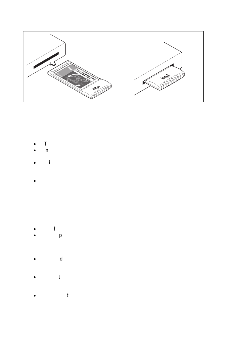
Hardware Installation
1. Turn on power to the computer and wait for Windows to load. (Windows
98SE, Me, 2000, or XP is required.)
2. Insert the CardBus Adapter into the CardBus PC Card slot on your
computer, then proceed to Step 3 to install drivers and software under
the Windows operating system.
11
Page 13

WARNING!!
To comply with the FCC and ANSI C95.1 RF exposure limits, it is recommended when using a
wireless device with an integrated antenna, for the Cardbus inserted into a laptop computer that
the antenna should not be positioned closer than 20 cm from your body or nearby
persons for extended periods of time while it is transmitting (or operating).
The Device must not be co-located or operating in conjunction with any other
antenna or radio transmitter. Installers and end-users must follow the installation instructions
provided in this user guide.
Radio Frequency Interference Requirements
This device is restricted to indoor use due to its operation in the 5.15 to 5.25 GHz frequency
range. FCC requires this product to be used indoors for the frequency range 5.15 to 5.25 GHz to
reduce the potential for harmful interference to co-channel Mobile Satellite systems. High power
radars are allocated as primary users of the 5.25 to 5.35 GHz and 5.65 to 5.85 GHz bands.
These radar stations can cause interference with and /or damage this device.
Page 14
Windows® Installation (98SE, Me, 2000, XP)
3. Windows will detect the adapter. Follow the procedures below for your
version of Windows, then continue with Step 4:
Windows 98SE
The "Add New Hardware Wizard " dialog will appear. Click Next.
x
Insert the Intel CD-ROM into your CD-ROM drive. If the
x
PRO/Wireless LAN Products menu appears, leave it open.
Click the New Hardware Wizard screen to make it active. Select
x
"Search for the best driver for you device (Recommended)," and
click Next, then select "CD-ROM drive" and click Next.
The Adapter Properties screen will appear. On the Settings tab:
x
(option a) click OK to install using a default profile or (option b) click
Configure to set up a profile using configuration information
obtained from your network administrator. On the My WLAN places
dialog, click the New button to create a new profile. Type a
configuration name and the SSID for your wireless network. Set up
security and other parameters if required. Click OK twice, then
Close.
On the Add New Hardware Wizard screen, click Finish.
x
When prompted to restart the computer, click No (restart manually
x
after completing software installation). Proceed to Step 4.
Windows Me
The "Add New Hardware Wizard " dialog will appear. DO NOT click
x
Next. Verify that "Automatic search for a better driver
(Recommended)" is checked.
Insert the Intel CD-ROM into your CD-ROM drive. Windows will
x
install the driver from the CD-ROM. If the PRO/Wireless LAN
Products menu appears, leave it open.
The Adapter Properties screen will appear. On the Settings tab:
x
(option a) click OK to install using a default profile or (option b) click
Configure to set up a profile using configuration information
obtained from your network administrator. On the My WLAN places
12
Page 15

dialog, click the New button to create a new profile. Type a
configuration name and the SSID for your wireless network. Set up
security and other parameters if. Click OK twice, then Close.
Click Finish on the Add New Hardware Wizard screen when the
x
driver installation is complete.
When prompted to restart the computer, click No (restart manually
x
after completing software installation). Proceed to Step 4.
Windows 2000
The "Add New Hardware Wizard " dialog will appear. DO NOT click
x
Next yet. Verify that "Automatic search for a better driver
(Recommended)" is checked.
Insert the Intel CD-ROM into your CD-ROM drive. Windows will
x
install the driver from the CD-ROM. If the PRO/Wireless LAN
Products menu appears, leave it open.
The Adapter Properties screen will appear. On the Settings tab:
x
(option a) click OK to install using a default profile or (option b) click
Configure to set up a profile using configuration information
obtained from your network administrator. On the My WLAN places
dialog, click the New button to create a new profile. Type a
configuration name and the SSID for your wireless network. Set up
security and other parameters if required. Click OK twice, then
Close.
Click Finish on the Add New Hardware Wizard screen. Proceed to
x
Step 4.
Windows XP
The "Found New Hardware Wizard" dialog will appear.
x
Insert the Intel CD-ROM into your CD-ROM drive. The driver files
x
will be copied to your hard drive. If the PRO/Wireless LAN Products
menu appears, leave it open.
If a Windows Logo testing dialog appears, click "Continue Anyway."
x
The My WLAN Places screen will appear. You can (option a) click
x
Next to install using a default profile or (option b) click Configure to
set up a profile using configuration information obta ine d from your
network administrator. On the My WLAN Places dialog, click the
New button to create a new profile. Type a configuration name and
the SSID for your wireless network. Set up security and other
parameters if required. Click OK twice, click Close.
On the Found New Hardware Wizard screen, click Finish. Proceed
x
to Step 4.
4. On the PRO/Wireless LAN Products menu screen, click Install Software
(if the menu screen is not visible, remove and re-insert the Intel CDROM to display it, or run autorun.exe from the Intel CD-ROM).
5. Click I Accept on the Software Agreement screen to continue.
6. Select Yes when prompted to install or upgrade PROSet II LAN
Software, then click Next.
13
Page 16

7. Select No (recommended) when asked if you want to install Access
Point Administration Tools, then click Next. (If you are a network
administrator, select Yes. See the Administrator's Guide in the online
User’s Guide for information on how to use the Administration Tools.)
8. After the software is installed on your computer, click Finish.
9. Restart the computer.
Installing the PCI Adapter
Package Contents
Intel® PRO/Wireless 5000 LAN PCI Adapter (model WPCI5000)
x
CD-ROM containing software and user docume ntat ion
x
Quick Installation Guide (this manual)
x
Hardware Installation
1. 2.
14
Page 17

3.
Note: Antenna is reverse-
threaded.
Typical installation, standard case Typical installation, tower case
Windows® Installation (98SE, Me, 2000, XP)
1. Install the PCI Adapter hardware according to the illustrations shown,
then close and secure the computer case.
2. Turn on power to the computer and wait for Windows to load. (Windows
98SE, Me, 2000, or XP is required.)
3. Proceed to Windows® Installation, Step 3, on page 12.
15
Page 18

Customer Support
Web and Internet Sites
Support: http://support.intel.com
x
Network Products: http://www.intel.com/network
x
Corporate: http://www.intel.com
x
Customer Support Technicians
For the U.S. and Canada
If you are using this product in conjunction with Intel® PRO/Wireless 5000
LAN hardware in a business or office environment and want customer
support, please call +1 916-377-7000 (7:00 – 17:00 M–F Pacific Time). You
can also visit the Intel customer support web site (http://support.intel.com).
For Worldwide Access
Intel has technical support centers worldwide. Many of the centers are
staffed by technicians who speak the local languages. For a list of all Intel
support centers, the telephone numbers, and the times they are open, refer
to the Customer Support Phone Numbers web site at
http://www.intel.com/support/9089.htm
Product Warranties
For details of product warranties, see the online manuals.
Regulatory and Safety Notices
All regulatory and safety notices are provided in the online manuals and on
the web at http://www.intel.com/support.
Software License Agreement
Software included with this product is protected by a specific Software
License Agreement, provided in the online manuals. By using this software
you agree to the provisions in the Software License Agreement.
Register Online
Register online to receive technical support, product upgrade notices,
information updates, and special offers. To register online, re-insert the Intel
CD-ROM and click Online Registration on the menu.
16
 Loading...