

Page 1
Formerly Omnipoint Technologies, Inc.
Redhawk™ II
GSM Wireless Terminal
Users Guide
© 2000 Xircom, Inc. All rights reserved.
All trademarks and copyrights are the property of Xircom, Inc.
Page 2

Redhawk II GSM Modem Users Guide Draft: 10/30/00 2
Part Number: 07100020 version 00B
SAFETY PRECAUTIONS
Important Safety Information
Some of the following informat i on may not apply to all devices described in this
manual. However, precautions should be observed when handling any electrical
device.
Save this manual, it contains important safety information and operating
!
instructions.
Do not expose the Redhawk II product to open flames.
!
Care should be taken so that liquids do not spill into the devices.
!
A qualified electrician should perform all primary connections to AC power.
!
Do not attempt to disassemble the product. Doing so will void the warranty. With
!
the exception of Subscriber Identification Modules (SIM), this product does not
contain consumer ser v ic eabl e com pon e nts.
Guidelines for Limiting RF Exposure
The Redhawk II products are GS M radio transc ei v ers, which operate under the
authority of 47 CF R Part 24, Subpart E of t he FCC Rules and Regulations. When
installed and o perated in accordance with the in structions provi ded in this manual ,
these devices comply with current F CC regulations regarding human exposure to
radio frequency - electromagnetic fields.
The following installation and operation restrictions apply to all Redhawk II products:
These devic es may only be use d i n fixed and mobile applications
!
Portable appli cations, as defin ed by the FCC, are prohibited
!
A separation di st ance of at least 20 c m (7 7/8) inches betw een the antenna a nd
!
body of the user and other person s m ust be maintained at all times
In FIXED applications antenna gain* is limited to a maximum of 7 dBi, with a
!
correspondi ng equivalent isotropic radiated power (EIRP) of 37 dBm / 5 W
In MOBILE applications antenna gain* is limited to a maximum of 3 dBi, with a
!
correspondi ng equivalent isotropic radiated power (EIRP) of 33 dBm / 3 W
Desktop and other uses of these devices where t he antenna can easi l y be relocated
!
are considered by the FCC to be mobil e applications.
* Antenna gain is defined as gain in dBi (dB referenced to an isotropic radiator) minus cabling loss.
NOTE: Additio nal care must be taken by the installer and/or user of the
Redhawk IITM products to ensure proper antenna selection a nd installation.
Adherence to the above conditions is necessary to comply with FCC
requirement s for safe operation regarding exposure to RF radiation.
© 2000 Xircom, Inc. All rights reserved.
All trademarks and copyrights are the property of Xircom, Inc.
Page 3

Redhawk II GSM Modem Users Guide Draft: 10/30/00 3
Part Number: 07100020 version 00B
Disclaimer
The information and instructions contained within this pu blication com pl y w i th
all FCC, NRLT, IM EI and other applic able codes in effe ct at the time of
publication. Xircom, Inc. disclaims all responsibility for any act, or breach of
law, code or reg ul ation, includi ng local or state codes, performe d by a t hi rd
party.
Xircom strongly recommends that all installations, hookups, transmissions, etc.
be performed by persons who are exp erienced in the fields of radio frequency
technologies. Xircom acknowledges that the i nstallation, s et up and
transmissi on guidelines contained within this publication are guidelines, and
that each inst al l ation may have v ari ables outside of the guidelin es contained
herein. Said variables must be taken into consideration when installing or using
the product, and Xircom, Inc. sh al l not be responsible for installati ons or
transmissions that fall outside of the parameters set forth in this publication.
Xircom shall not be liable for consequential or incidental damages, injury to any
person or property, anticipated or lost profits, l oss of time, or oth er losses
incurred by Customer or any thir d party in connection with the installation of
the Products or Customer's fail ure to comply with t he i nformation and
instruction s contained herein.
Beta Release Notes
Data Services
The current soft w are release does not support transpar ent circuit switched data or
Group 3 Fax. These services will be added in subsequent versions.
AT Commands
The current software version does not support all AT commands listed in this
document. Please reference the at tached Errata sh eet for a list of the nonfunctioning AT commands. These commands will be added in future software
versions.
PUK Procedure
The PUK procedure outlined in this document will be changing.
© 2000 Xircom, Inc. All rights reserved.
All trademarks and copyrights are the property of Xircom, Inc.
Page 4
Redhawk II GSM Modem Users Guide Draft: 10/30/00 4
Part Number: 07100020 version 00B
DECLARATION OF CONFORMITY
Xircom, Inc. of 2300 Corporat e Ce nt e r Drive, Th ousand Oaks, CA 91360 declares
that the Xircom Redhawk™ II GSM Radio Module, model 2110-1300 (900/1800) is
in conformance w i th all relevant essential requir ements of the European Council
Directives listed below:
1999/5/EC Radio and Telecommunicati on s Terminal Equipment Directive
(Following Annex III of this Directive)
89/336/EEC EMC Directive with Amendme nt 92/ 31/EEC and 93/68/EEC
72/23/EEC Low Voltage Directive wi t h Amendment 93/68/EEC
This declarat ion is made based upon complia nce to the followi ng standards:
EN 60950 (1992 w/ A1, 2, 3, 4) Safety of Information Techn ol ogy Equipment,
Including El ect rical Business Equipment
ETS 300 342-1 Edition 2 (June 1997) Radio Equipment and Syst ems (RES);
Electromagnetic Compatibility (EMC) for
European digi t al cellular telecommunications
system (GSM 900 MHz and DCS 1800 MHz).
Part 1: Mobile and portable radio and ancillary
equipment.
TBR 19 Edition 3 (October 1996) European digital cell ular telecommunications
system (Phase 2); Attachment requirements for
global system for mobile comm unications (GSM)
mobile stations; Access
TBR 31 Edition 2 (March 1998) Digital cellular telecommunications system
(Phase 2); Attachment requirements for mobile
stations in the D CS 1800 band and additional
GSM 900 band; Access
Xircom further declares that all ess ential radio test suites have been carried out.
This declaration is made under our sole responsibility.
Authorized Si gnature: ______ ______________ _____________ Date:
__________________
R.W. Bass
Vice President, O perations
Xircom Europe, Middle East, and Africa
Veldkant 31
2550 Kontich, Belgium
© 2000 Xircom, Inc. All rights reserved.
All trademarks and copyrights are the property of Xircom, Inc.
Page 5

Redhawk II GSM Modem Users Guide Draft: 10/30/00 5
Part Number: 07100020 version 00B
TABLE OF CONTENTS
REDHAWK™ II GSM WIRELESS TERMINAL
USERS GUIDE
Safety Precautions......................................................................................... 2
Important Safety Information....................................................................... 2
Guidelines for Limiting RF Exposure.............................................................. 2
Disclaimer................................................................................................. 3
Beta Release Notes .................................................................................... 3
DECLARATION OF CONFORMI TY..................................................................... 4
.............................................................................................. 1
.................................................... 1
TABLE OF CONTENTS ................................................................................... 5
Product Overview .......................................................................................... 7
Model Variation ......................................................................................... 7
General Description.................................................................................... 8
Summary of the Features for the Redhawk II Modem....................................... 9
Front Panel ............................................................................................. 10
GSM Overview........................................................................................ 14
Redhawk II Programming Manual................................................................ 15
Backward Compatibility ............................................................................ 15
Modes of Operat ion.................................................................................. 15
Provisioning the SIM..................................................................................... 19
GSM Services Supported by the Redhawk II Modem...................................... 19
Selecting the Modes of Operation............................................................... 19
Antenna Selection........................................................................................ 20
Connector............................................................................................... 20
Antenna Selection.................................................................................... 20
Antenna Selection: Performance Guidelines.................................................. 20
Modem Antenna Location and Network Communication................................. 21
Installation & Initialization ............................................................................. 23
Guidelines for Limiting RF Exposure............................................................ 23
Installation and Verification ....................................................................... 23
SMS Message Verification......................................................................... 30
Final Verifica ti on...................................................................................... 34
Detailed Specifications.................................................................................. 35
Physical Dimensions and Weight ................................................................ 35
Operating Power...................................................................................... 35
Care and Maintenance.............................................................................. 36
Environmental Specifications ......................................................................... 37
© 2000 Xircom, Inc. All rights reserved.
All trademarks and copyrights are the property of Xircom, Inc.
Page 6

Redhawk II GSM Modem Users Guide Draft: 10/30/00 6
Part Number: 07100020 version 00B
Climatic, Operational................................................................................ 37
Repair and return Policy................................................................................ 39
regulations and Compliance........................................................................... 40
GSM Full Type Ap pr oval (FTA)................................................................... 40
FCC notices............................................................................................ 40
CLASS A................................................................................................ 40
CLASS B ................................................................................................ 41
Human Exposure Compliance..................................................................... 41
NRTL / IMEI Approval............................................................................... 42
EMC/Safety Requirements for the Countries of the European Union (EU) .......... 42
EMC/Safety Requirements for Other Countries.............................................. 43
Electromagnetic Compatibility (EMC) and Safety Requirements....................... 43
Glossary And Acr o nyms................................................................................ 45
Appendix A................................................................................................. 48
Installing the Remote Antenna ................................................................... 48
Contacting XIRCOM..................................................................................... 54
© 2000 Xircom, Inc. All rights reserved.
All trademarks and copyrights are the property of Xircom, Inc.
Page 7
Redhawk II GSM Modem Users Guide Draft: 10/30/00 7
Part Number: 07100020 version 00B
PRODUCT OVERVIEW
The Redhawk II Modem is built around the Eagle II™ Data Terminal , a compact,
wireless modem that utilizes the international standard Global System for Mobile
communications (GSM). The dat a terminal enables low-cost, application-specific,
two-way communication and control. It takes f ull ad vantage of GSM capabilit ies
such as Subscri ber Identity Modules (SIM), which are "smart cards" that provides
numerous advantages.
Over-the-air communication lets the Redhawk II terminal accomplish tasks that
previously required on-site visits and offers innovative new service capabilities never
before available. In addition, t e rminal authenti cation and dat a encryption ensures a
more confide ntial communic ation link betwe en the terminal us er and the data
recipient.
Model Variation
Redhawk II modems are available in two config urations:
Redhawk II: This modem is GSM only and supports Short message service (SMS),
!
unstructured supplementary service data (USSD), voice, and circuit switch ed data
(transparent and non-transparent mode) up to 9.6 Kbps.
900 MHz & 1800 MHz: Part # 2110-1300
!
900 MHz & 1900 MHz: Part # 2110-1500
!
Redhawk IIG: This modem has the same GSM functionality as the Redhawk II with
!
the addition that it is GPRS hardware ready. It provides GPRS packet data up to and
including Class 10, in addition to Short message service (SMS), unstructured
© 2000 Xircom, Inc. All rights reserved.
All trademarks and copyrights are the property of Xircom, Inc.
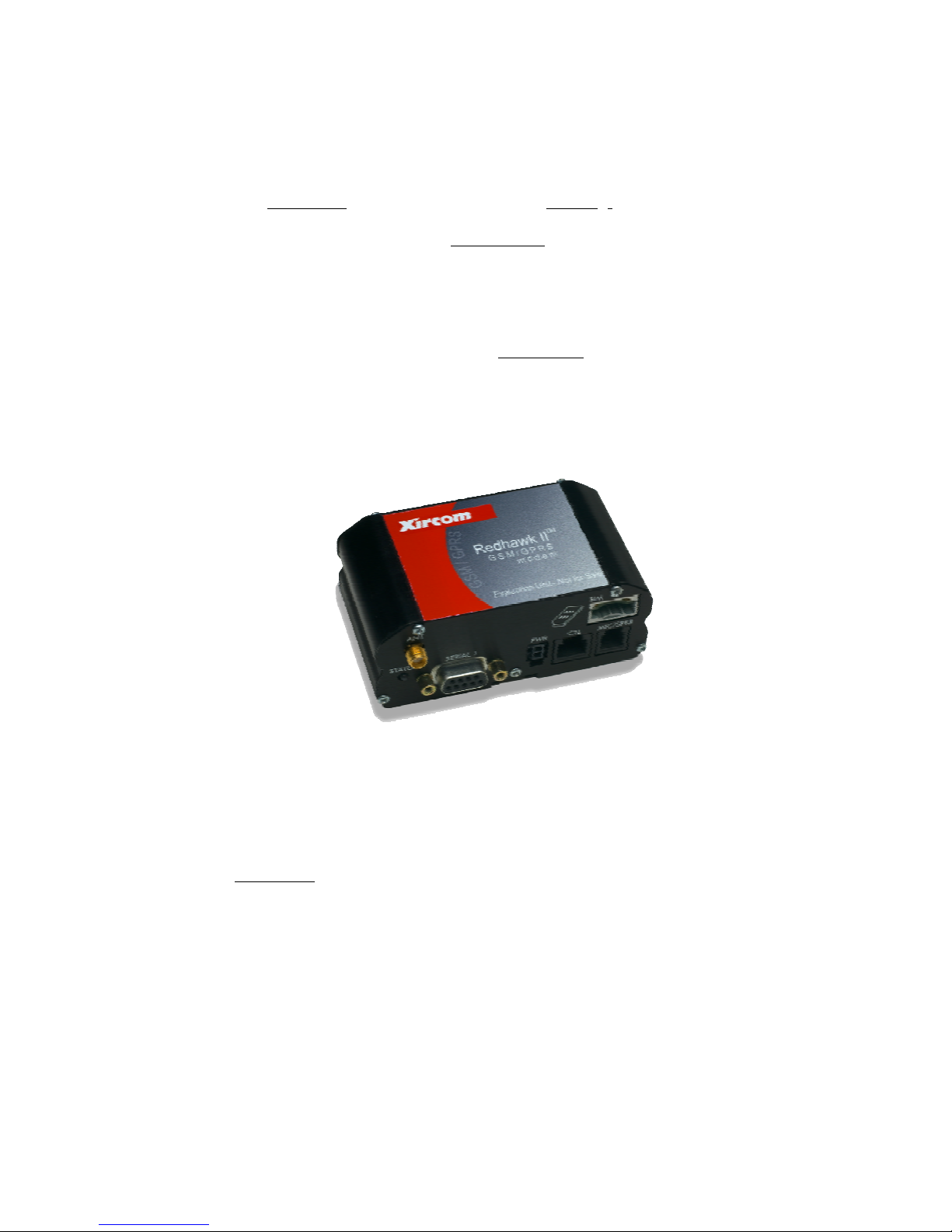
Figure 1: Redh aw k I I Modem
Page 8
Redhawk II GSM Modem Users Guide Draft: 10/30/00 8
Part Number: 07100020 version 00B
supplementary service data (USSD), voice, and circuit switched data (transparent
and non-transparent mode) up t o 9. 6 Kbps.
900 MHz & 1800 MHz: Part # 2210-1300
!
900 MHz & 1900 MHz: Part # 2210-1500
!
General Description
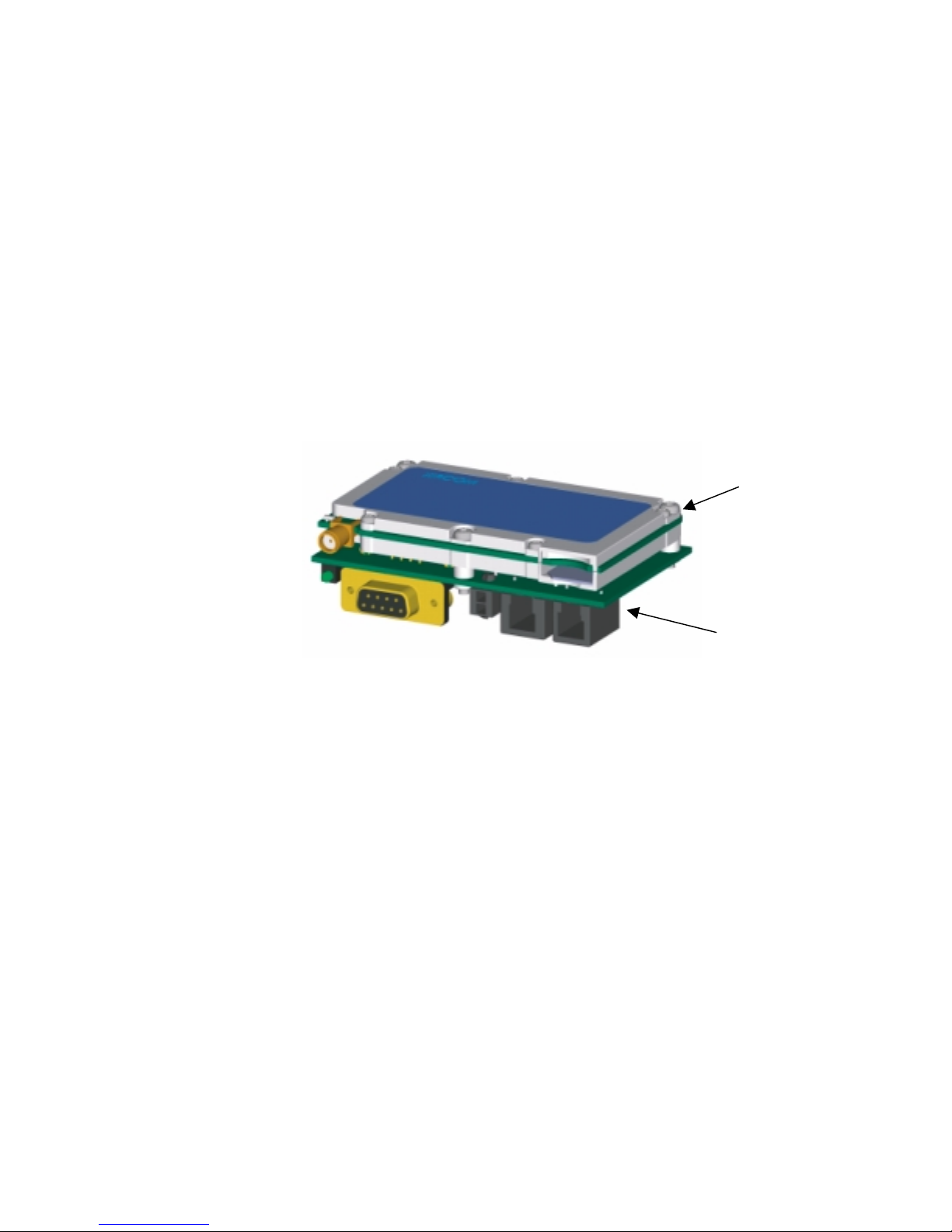
The Redhawk II c ontains the Eagle II radio data modu le and a Carrier Board assembly
in a aluminum housing. The Eagl e I I radio module provides the GSM ov er t he air
radio link and m odem command f unctions. More det ai led information on the Eagle II
can be found in the Ea gle II Technical Manual (part # 07100017). The Carri er Board
provides DC to DC conversion and standard interface connections wi th drivers for
two serial interfaces, a voice interface, and DC power.
Eagle II Terminal
Carrier Board
Figure 2: Redh aw k I I Modem Breakout
The modem operates under a wide range of DC input p ower. (+5V to +28V)
Communication is through an RS-232 physical interface, using t he GSM - AT
command set. Other unique AT commands are also a v ai lable, provi ding the
opportunity to m onitor and report n etwork conditi ons that may be relev ant to the
management of multiple deployed terminals. See the Programmers Manual for details
on these unique commands.
© 2000 Xircom, Inc. All rights reserved.
All trademarks and copyrights are the property of Xircom, Inc.
Page 9
Redhawk II GSM Modem Users Guide Draft: 10/30/00 9
Part Number: 07100020 version 00B
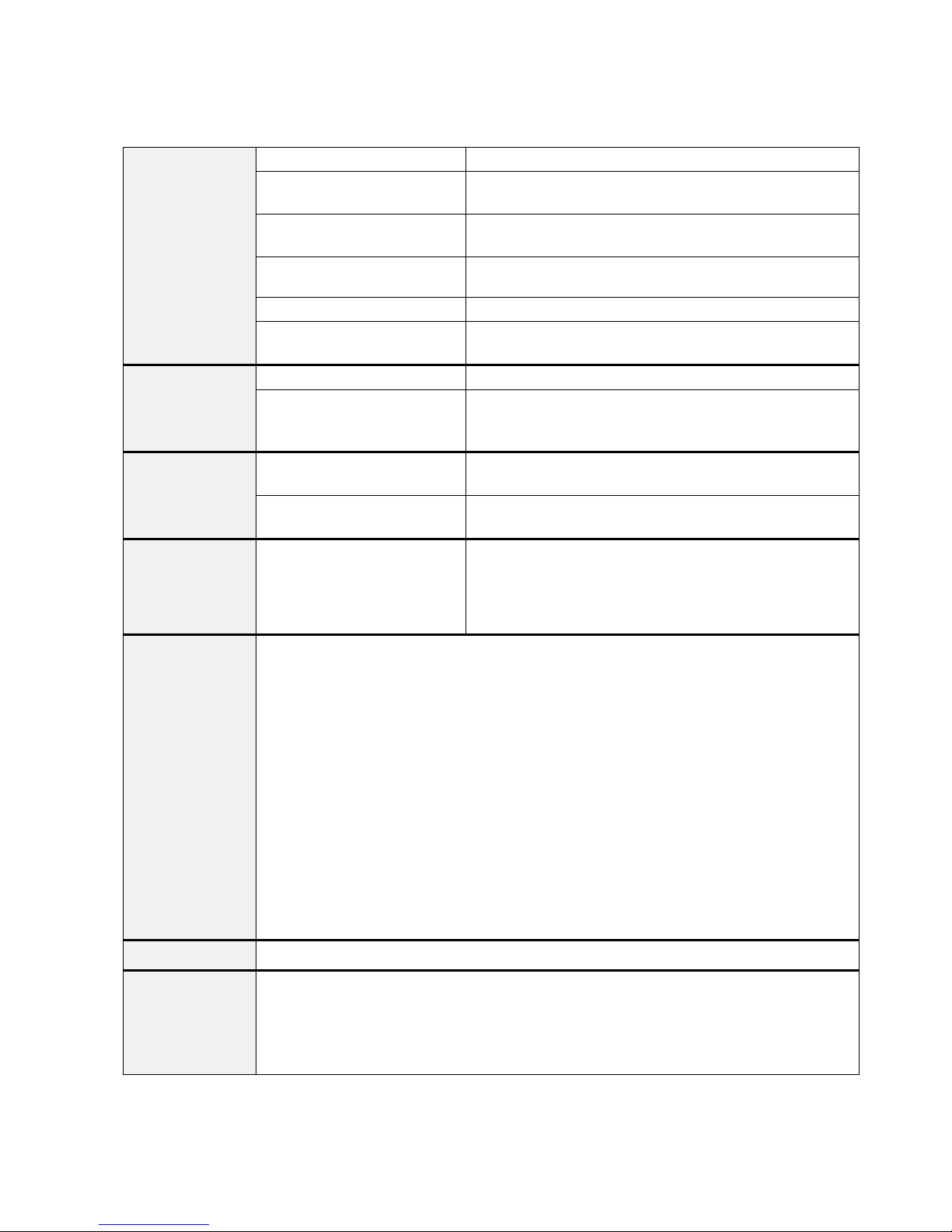
Summary of the Features for the Redhawk II Modem
Interface
Power
Radio Features
Regulatory
GSM
Functionality
SIM
International
Mobile Equipment
Identity (IMEI)
Primary serial port V.24 protocol, 3 V (5 V tolerant) levels
Secondary serial port Secondary 3 V serial port (Any functions other than SMS
messaging requires the development of custom applications)
Voice Supports three vocoder modes: half-rate, full-rate, and enhanced
full-rate (EFR)
Antenna Female SMA
Command protocol AT command set
Subscriber Identification Module
(SIM)
Electrical power Fixed DC voltage
Peak currents and average power
dissipation
Frequency bands GSM 900, DCS 1800, and PCS 1900 capability, depending on
GSM features supported Provides for all GSM authentication, encryption, and frequency
Agency approvals
"
Mobile-originated and mobile-terminated SMS messages: up to 140 bytes or up to 160 GSM 7bit ASCII characters. Up to 255 messages may be concatenated.
"
Reception of Cell Broadcast Message
"
SMS Receipt acknowledgement
"
Circuit Switched Data (Transparent & Non-transparent fixed at 9.6 Kbps
"
Voice
"
Group 3 Fax
"
Supports GSM Phase 2+
"
Supports Unstructured Supplementary Service Data (USSD)
Not all GSM operators support USSD. For more information, contact Customer Support for the
GSM operator.
Redhawk IIG hardware is capable of supporting General Packet Radio Services (GPRS) when
configured with optional memory. (GPRS Class B, Multislot Class 10 software will be available at a
later date.)
3 V Mini-Subscriber Identity Module (SIM) carrier and interface on board
The IMEI allows defective or stolen equipment to be barred from using the GSM network.
The IMEI number is unique to each Redhawk II modem. It reveals the manufacturer, the country of
production, and the type approval facility. When the Redhawk II modem is powered on and tries to
register with the GSM network, the network pr ovider checks the IMEI. If the IMEI is valid and has
not been barred, the Redhawk II modem is allowed to register with the network.
3 V mini-SIM carrier and interface on board
Refer to the Operatin g Power table in the Techn i cal
Specifications section for peak currents and average power
dissipation for various modes of operation.
the product.
hopping algorithms.
"
GSM Type Approval
"
FCC Certification (Part 24)
"
CE (European Community Certification)
"
IC (Industry Canada) available
© 2000 Xircom, Inc. All rights reserved.
All trademarks and copyrights are the property of Xircom, Inc.
Table 1: Summary of Features
Page 10
Redhawk II GSM Modem Users Guide Draft: 10/30/00 10
Part Number: 07100020 version 00B
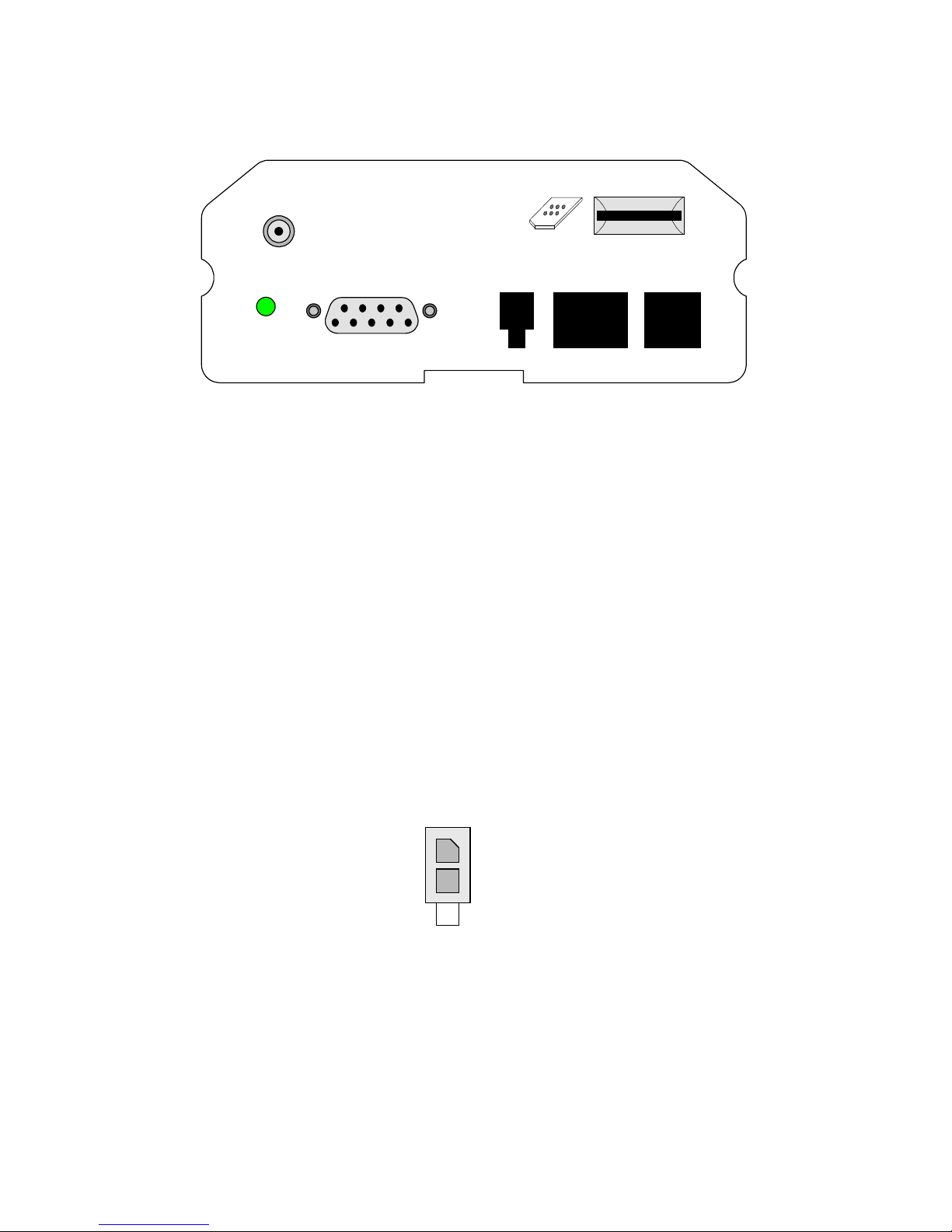
Front Panel
ANT
STATUS
SERIAL 1
Antenna Connector (ANT)
The Redhawk II modem is designed to support interchangeable antenna types,
provided that each antenna h as 5 0 -ohm impeda nce and has been t uned to the
frequency band intended. It comes standard with a female SMA-type connector.
DC Power (PWR)
The Redhawk II modem requires an inp ut voltage of 5.0 VDC to 28.0 VDC. The
input source v oltage ripple should be less than 20% of the average supply voltage
peak-to-peak under normal operating conditions.
SIM
MIC/SPKRCTLPW R
Figure 3: Redh aw k I I F ront Panel
The power cable m at i ng connector is a Molex part #43025-0200 (shell ) and
#43030-0009 (bag of pins) or #43030-0003 (reel of pins).
PWR
+V (VIN)
-V (GND)
Figure 4: Input Power Connector
© 2000 Xircom, Inc. All rights reserved.
All trademarks and copyrights are the property of Xircom, Inc.
Page 11

Redhawk II GSM Modem Users Guide Draft: 10/30/00 11
Part Number: 07100020 version 00B
Pin
Number
1 VIN From CPE Electrical power input to Redhawk II modem:
2 GND From CPE Electrical power return for digital and analog
Signal
Name
Direction Functionality
5.0 VDC to 28.0 VDC
grounds.
Table 2: Power C on nector Pin Out
Primary Serial Interface (SERIAL 1)
This serial I/O interface (RS-232) uses a DB-9 connector and supports auto baud capability from
300 bps to 19200 bps with hardware handshake flow control.
Pin
Number
1 DCD0_DS To CPE Data Carrier Detec t 0. DCE Output sign al . Active low. Main
Signal
Name
Direction Functionality Voltage
3 V
serial interface data carrier detect signal. Connects to a DTE,
CD, Carrier Detect pin.
Level
2 RX0_DS To CPE Receive data 0. DCE Output s i gnal. Main serial interface
transmit data signal. During idle or reset, signal will be a logic
1. Connects to a DTE, RX, receive data pin.
3 TX0_DS From CPE Transmit data 0. DCE Input signal. Active low. Main serial
interface receive data signal. During idle o r reset, signal will be
a logic 1. Connects to a DTE, TX, transmit data pin.
4 DTR0_DS From CPE Data Terminal Ready 0. DCE Input signal. Active low. Main
serial interface data terminal ready signal. Connects to a DTE,
DTR, Data Terminal Ready pin.
5 GND_IN From CPE Electrical power return for digital and analog grounds.
6 DSR0_DS To CPE Data Set Ready 0. DCE Output signal. Active low. Main serial
interface data set ready signal. Connects to a DTE, DSR, Data
Set Ready pin.
7 RTS0_DS From CPE Request-To-Send 0. DCE Input signal. Active low. Main serial
interface request to send signal. Connects to a DTE, RTS,
Request-To-Send pin.
8 CTS0_DS To CPE Clear-To-Send 0. DCE Output signal. Active low. Main serial
interface clear to send s i gnal. Connects to a DTE, CTS, Clear
to send pin.
9 RI0_DS To CPE Ring Indicator 0. DCE Output signal. Active low. Main serial
interface ring indicator signal. Connects to a DTE, RI, Ring
Indicator pin.
3 V
5 V or
3 V
5 V or
3 V
3 V
5 V or
3 V
3 V
3 V
NOTE: The maximum length for the Primary Serial cable is 50 feet.
© 2000 Xircom, Inc. All rights reserved.
All trademarks and copyrights are the property of Xircom, Inc.
Table 3: Primary Serial Connector Pin Out
Page 12

Redhawk II GSM Modem Users Guide Draft: 10/30/00 12
Part Number: 07100020 version 00B
Secondary Serial Control Interface (CTL)
This serial I/O interfaces (RS-232) that support auto baud capability from 300 bps to 19200
bps.
Connector:
Pin
Number
1 GPIO2_RJ To/From CPE General purpose I/O. Used as a general purpose input or output
2 GPIO1_RJ To/From CPE General purpose I/O. Used as general a purpose input or output
3 RX_D From CPE Receive Data 1. DTE Input signal. Secondary serial-interface
4 TX_D To CPE Transmit Data 1. DTE Output signal. Secondary serial-interface
5 GND _RJ To CPE Electrical power return for digital and analog grounds.
6 GPIO0_RJ To/From CPE General purpose I/O. Used as general a purpose input or output
RJ-11
Signal
Name
Direction Functionality Voltage
line for monitoring or control of external devices. Requires
customized stack softwar e to implement. Leave sig nals
disconnected if function is not used.
line for monitoring or control of external devices. Requires
customized stack softwar e to implement. Leave sig nals
disconnected if function is not used.
receive data signal. Used as a debug interface for test purposes.
Leave signal disconnected if function is not used.
transmit data signal. Used as a debug interface for test
purposes. Leave signal disconnected if function is not used.
line for monitoring or control of external devices. Requires
customized stack softwar e to implement. Leave sig nals
disconnected if function is not used.
Level
3 V
3 V
5 V or
3 V
3 V
3 V
Table 4: Secondary Seri al Connector Pin Out
NOTE: The maximum length for the Secondary Serial cable is 50 feet .
Voice interface (MIC/SPKR)
Uses an RJ-9 connector and prov i des differential m i crophone inputs and speaker outputs.
© 2000 Xircom, Inc. All rights reserved.
All trademarks and copyrights are the property of Xircom, Inc.
Page 13
Redhawk II GSM Modem Users Guide Draft: 10/30/00 13
Part Number: 07100020 version 00B
Pin
Number
1 MIC0N From CPE Microphone Negative. Negative input pin from an electret-type
2 SPK0N To CPE Speaker Negative. Negative output pin. Low side of a push-pull
3 SPK0P To CPE Speaker Positive. Positive output pin. High side of a push-pull
4 MIC0P From CPE Microphone Positive. Positive input pin from an electret-type
Signal
Name
Direction Functionality Voltage
microphone. Nominal microphone differential voltage should be
2.0 volts. Impedance not less th an 900 ohms. Leave signal
disconnected if function is not used.
amplifier. Speaker impedance 15 oh ms, minimum. Speaker
capacitance of 700 pF, maximum. Driver voltage is 4.5 V
peak-to-peak. Leave signal disconnected if function is not used.
amplifier. Speaker impedance 15 oh ms, minimum. Speaker
capacitance of 700 pF, maximum. Driver voltage is 4.5 V
peak-to-peak. Leave signal disconnected if function is not used.
microphone. Nominal microphone differential voltage should be
2.0 volts. Impedance not less th an 900 ohms. Leave signal
disconnected if function is not used.
Table 5: Voice Con n ector Pin Out
Subscriber Interface Module (SIM)
Level
The SIM, an inte gral part of any GSM terminal device, i s programmed with
subscriber information. The SIM is not provided with the Redhawk II unit and m ust
be provided by t he GSM service subscriber. Care must be taken to prote ct the SIM.
A GSM terminal will not operate without the SIM installed.
The user information consists of an identity (IMEI n umber) registered w i th the GSM
provider, and a n encryption Ki (pronounced key). T he S I M consists of a
microprocess or chip and memory, installed on a pl ast ic card. Redhawk II uses the
"mini-SIM" or pl ug in configuration. The SIM, which is removable, slips into a slot on
the front of the modem.
The SIM card performs authentication. To gain access to the GSM network, the
network must recognize the IMEI number and the term inal must be abl e to properly
decrypt the data sent by the network. The SIM also serves as a buffer for Incom ing
and Stored SMS m essages, or when a radio link is not available, store an outgoing
message unti l a network link is established.
Power must be off w hen installing or re m oving a SIM card.
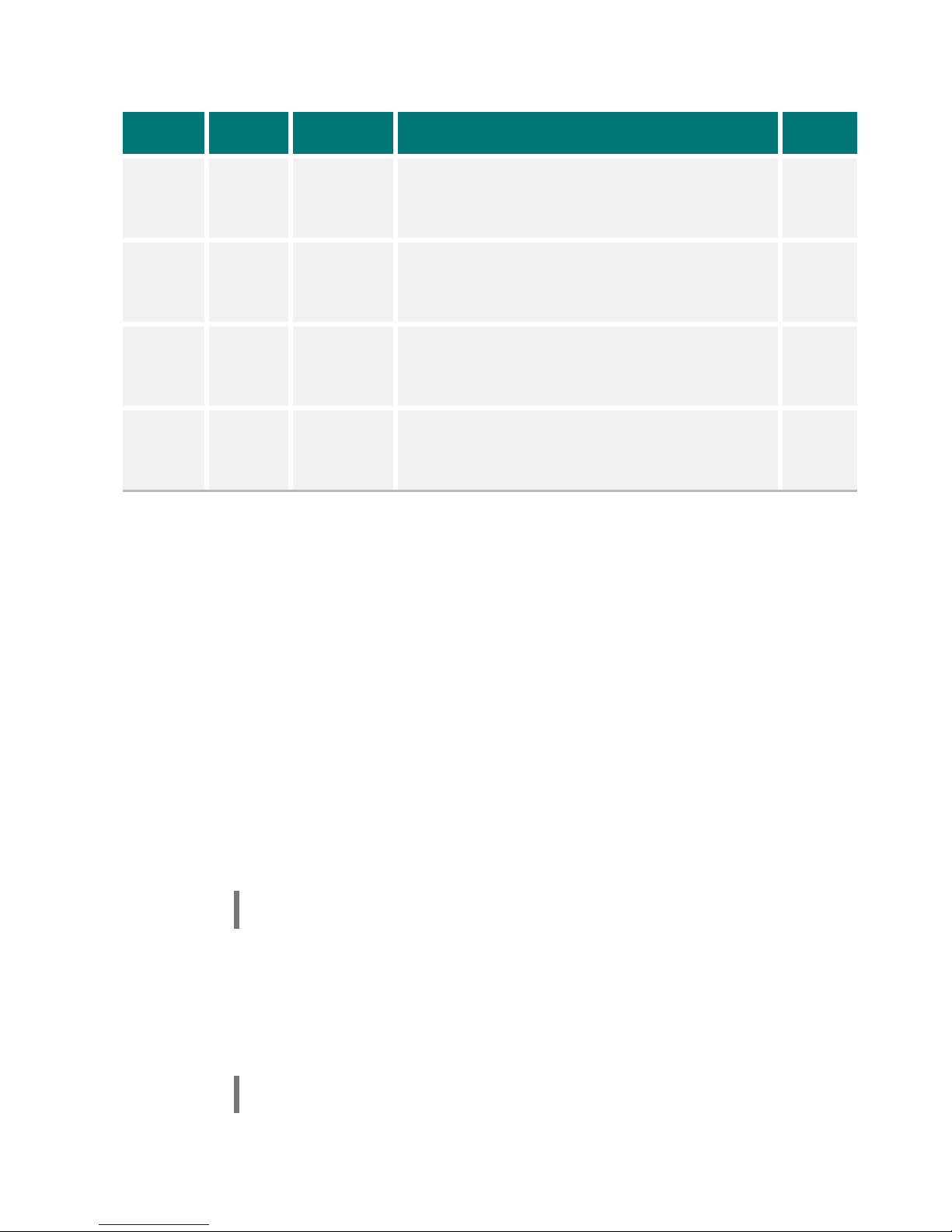
Status Indication (STATUS)
The Redhawk II m odem provides a mult i -color LED that in di cates the current l i nk
status and sig nal quality.
Note:
The LED illuminates any time power is applied to the Redhawk II modem.
© 2000 Xircom, Inc. All rights reserved.
All trademarks and copyrights are the property of Xircom, Inc.
Page 14
Redhawk II GSM Modem Users Guide Draft: 10/30/00 14
Part Number: 07100020 version 00B
LED Color Link Status Signal Quality
Green
Orange
Solid Red
Flashing
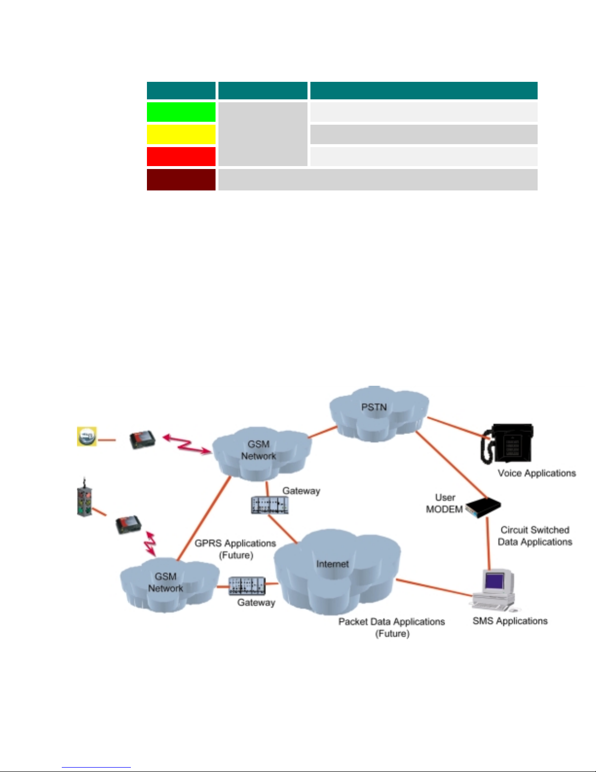
GSM Overview
The GSM communications stan dard, already wi del y deployed in Eur ope, Asia, and
North America, overcomes many of the drawback s found in other wireless telemetry
approaches. The GSM communications network was designed from the ground up,
for reliable and inexpensive di gi tal data transfers.
The GSM network (Figure 4) employs integrated data and data-friendly capabilities
such as short mes sage services, circuit switched dat a and, soon, GPRS, w hich
brings the best of wireless and packet data into harmony and will make new services
even more practical and affordable. In many countries around the world, especially
in Western Euro pe, GSM-based networks are the onl y digital networks deployed.
Red
Modem is attached
to the network
Modem is in Start-up mode or is not attached to the network
Link signal is optimal
Link is less than optimal but is acceptable
Link is unacceptable
Figure 5: Redhawk II terminal deployment in a GSM network
© 2000 Xircom, Inc. All rights reserved.
All trademarks and copyrights are the property of Xircom, Inc.
Page 15

Redhawk II GSM Modem Users Guide Draft: 10/30/00 15
Part Number: 07100020 version 00B
The Redhawk II modem leverages existing public GSM networks, as opposed to
other systems that require the utility to build, operate, and maintain expensive
private wirele ss networks.
Redhawk II Programming Manual
For greater flexibility that enhances the usability of the Redhawk II Modems, Xircom
has provided an AT Command s - Prog rammers Manual. Part #07100014-00A.
This manual goes into greater detail, in an easy to read format, on the enhanced
programming capabilities specific to the Redhawk II system.
Backward Compatibility
GSM functionality is forever evolving. Subsequently, in order to maintain the highest
standards, the Redhawk II modems will be backward compatible with new GSM
functionality such as General Packet Radio Service (GPRS). Applications supported
with early current versions of the modem will continue to be supported, as GSM
technology e v ol ves to GPRS, and then on to third generation tec hnologies, which are
now in the process of standardi zation and development.
Modes of Operation
Redhawk II offers several mod es of operation t o address a variety of application
requirements.
Circuit Switched Data
Circuit switched data is the most widespread and traditional means of data and
voice transmi ssion available today. A circuit switched connect i on occupies one
network line for the entire length of data transmission and duri ng this time, no other
user may access t his network line. A circuit switched connection i s the optimal
means for transmi tting any cont i nuous amount of data, such as vide o transmission
or voice.
A common exam pl e of a circuit switched network is the public tele phone system.
When person A pi cks up the telepho ne and dials the number of person B, the
network determ ines and assigns a path for that transmission. The signal travels
through each assigned circuit switch to complete the connection.
Once the signal has reached perso n B, a continuous two-way transmission path has
been establi shed. On a long dist ance call, for ex ample, many circuits would nee d to
be connected together to make the call possibl e. These circuits are dedicated to the
call for the duration of the transm i ssion and cannot be shared by oth er users. This
requires substantial network resources to be allocated per user.
Transparent and Non Transparent Transmissions
GSM provides two connection modes of transmission: trans parent and nontransparent. All Redhawk II models support both modes. The transparent data mode
delivers a service with a variable error rate, with a guar anteed throughp ut and delay,
whereas the non-transparent mode delivers a constantly low forwar d error correction
rate, but with a n on-guaranteed throughput or delay.
© 2000 Xircom, Inc. All rights reserved.
All trademarks and copyrights are the property of Xircom, Inc.
Page 16

Redhawk II GSM Modem Users Guide Draft: 10/30/00 16
Part Number: 07100020 version 00B
The non-trans parent service deli v ers the most reli abl e performance a nd is closest to
using a modem over a fixed telep hone line. Not all GSM service provid ers support
transparent mode. In those cases, the unit switches automatically to non-transparent
mode.
Short Message Service
To accommodate smaller messages, GSM uses short message service (SMS) for
efficient and timely data transmission and data retrieval. SMS is a point-to-point,
storage and fo rw arding, message service that is used in data transmissions such as
paging, notification, news flashes, and inf ormation retrieval .
Short messages can carry up to 140 8-bit c ha racters. (160, 7-bit character s
available – See Programmers Manual f or configuration)
Short Messages can be sent and received simultaneously with a voice or data call
and are sent above the voice or data in the overhead-signaling p ath (Traffic &
Bearer).
Although simil ar in concept to tra di tional paging, t he primary differe nce is that SMS
is not geographically restricte d a s paging systems are. Moreover, the GSM network
stores and resends the message if the receiver’s handset is turned off (In some
cases, if a pager is t urned off, the me ssage is simply lost).
Listed below are the essential characteristics and assumptions regarding the form of
SMS supported by the Redhawk II family of modems.
Support of both mobile origin ated and mobile t erm inated SMS.
!
Delivery of message to either designated telephone numbers.
!
8-bit data
!
Message Class 1
!
Message concatenation up to 255 messages (Verify with s ervice provider that
!
support for this capability is available)
Up to 140 ASCII Character per message using 8-bit data mode. ( 160 characters
!
if 7bit GSM ASCII used)
Status report in di cator not sent to SME
!
More Messages to Send (MMS) configuration.
!
Validity Period
!
Service Center Time Stamp
!
Alert SMS-SC
!
Priority and Message Waiting
!
Message Waiting
!
In addition to t he above, the following importa nt SMS functions are supported:
© 2000 Xircom, Inc. All rights reserved.
All trademarks and copyrights are the property of Xircom, Inc.
Page 17

Redhawk II GSM Modem Users Guide Draft: 10/30/00 17
Part Number: 07100020 version 00B
!
Submit a SMS TPDU to an SMS-SC, and store a copy of it until either a report arrives from
the network or from the network, or a timer expires
Receive a SMS TPDU from an SMS-SC
!
Return a deliver y report to the network for a previously received message
!
Receive a report f r o m the network
!
Notify the network when it has memory capacity available to receive one or
!
more SMS messa ges after it has previously rejecte d a m essage because i ts
memory capacit y w as exceeded
Support for Unstructured Supplementary Services Data
Unstructured S upplementary Services Data (USSD ) is a supplementary service to
allow for custom features by GSM ser v i ce providers. Th e m ain distinctio n bet ween
USSD and SMS is that the originator is guaranteed a real-time response and
acknowledg em ent in USSD, whereas SMS provides no such guar antee.
Put simply, USSD allows the transmission of strings o f characters between the
terminal and network in a tran sparent fashion. Both mobile-ini tiated and net w orkinitiated USSD transactions have been standardized in the GSM specifications. Such
transactions are normally in the form of a request character string followed by a
response charact er strin g.
Voice
In the case of GSM handsets, a valid USSD string is keyed into the handset (e.g.,
*#1446#) and the SEND key is pres sed.
The characters of the request string are restricted to i nt egers (0-9), has h ( # ) and
!
star (*).
The characters of the response stri ng can be numeric or alphabet character.
!
USSD may be more appropriate for potential applications where a real-time response
is required, su ch as point of sales. The Redhawk II modem supports all forms of
USSD, both mobile and network initiated. P l ease note that (U SSD is a GSM
supplementary service requiri ng subscription. )
The Redhawk II modem has full voice capabilities, provided the necessary
connections have been made for the speaker and microphone pins on the 60-pin I/O
connector. The AT commands and their r esponses allow th e user to enter and
receive information from the Redhawk II modem. These functions include the ability
for dialing, f or providing on-h ook or off-hook, and for controlling other aspects of the
voice call interface.
The Redhawk II modem supports three vocoder compression algorithms for voice
communication: half-rate, full-rate, and enhanced full-rate (EFR)
© 2000 Xircom, Inc. All rights reserved.
All trademarks and copyrights are the property of Xircom, Inc.
Page 18

Redhawk II GSM Modem Users Guide Draft: 10/30/00 18
Part Number: 07100020 version 00B
General Packet Radio Service (GPRS)
GPRS is the next step in GSM data services: a fully packet-based protocol service
with direct access to the Internet. By bringing th e best features of messaging,
circuit-switched services, an d packet data into harmony, GPRS promises to make
new applicati ons even more practical and affordable. Future releases of the
Redhawk II modem will support GPRS mode. Currently, the Redhawk II modem is
hardware-re ady for GPRS, if the opt ional memory upgrade is installed.
© 2000 Xircom, Inc. All rights reserved.
All trademarks and copyrights are the property of Xircom, Inc.
Page 19

Redhawk II GSM Modem Users Guide Draft: 10/30/00 19
Part Number: 07100020 version 00B
PROVISIONING THE SIM
The GSM SIM can support optional featur es or services. Most GSM operators
typically configure the SIM to send/receive voice calls and t o receive SMS; how ever,
some may require an additional tariff to enable the SIM to send SMS. The
transmission of data and fax are also additional services that may require tariffs an d
additional provisioning. Each of these services has two separate modes that mu st be
enabled to all ow the service:
Mobile-origi nated (MO): allows making a servi ce request (such as, making a call
!
or sending an SMS)
Mobile-termi nated (MT). allow s receiving a serv i ce request (such a s, receiving a
!
phone call or an SM S)
It is imperative for the Redhawk II modem that the SIM be configured for the
optional services that are required for the application.
GSM Services Supported by the Redhawk II Modem
The Redhawk II modem supports four GSM services (modes of operation) that must
be enabled by t he operator:
Voice calls (MO and MT): requires a telephone number
!
SMS (MO and MT): uses the telephone number for Voice
!
Fax calls (MO and MT): requires a telephone number
!
Circuit-switched data calls (MO and MT): requires a telephone number
!
The GSM SIM can have as many as three tele phone numbers: one n um ber for voice
calls and SMS, one number for fax c al l s, and one number for data calls.
Selecting the Modes of Operation
When provisi oning the SIM for t he Redhawk II modem, enable the following mode s
of operation:
Voice calls: c onfigure the SIM f or both MO and MT servi ce (to send and receive)
!
SMS: configure the SIM either for MT alo ne (to receive) or for b ot h MO and MT
!
(to send and recei ve)
Data: configur e t he SIM either for MO alon e (to send) or for both MO and MT (to
!
send and receive)
Voice SMS Data Fax Function
MO/MT MT MO X Voice calls, receive SMS, make data calls
MO/MT MT/MO MO X Voice calls, receive/send SMS, make data calls
MO/MT MT/MO MO/MT X Voice calls, receive/send SMS, make/receive data calls
© 2000 Xircom, Inc. All rights reserved.
All trademarks and copyrights are the property of Xircom, Inc.
(requires an additional data telephone number)
Page 20

Redhawk II GSM Modem Users Guide Draft: 10/30/00 20
Part Number: 07100020 version 00B
ANTENNA SELECTION
Connector
The modem antenna connector is a female SMA type. The modem is designed to
support interc hangeable ante nna types provid ed they have impedance of 50 ohms.
Antenna Selection
If possible, a suitable omni-directional antenna should be mounted directly to the
SMA connector on t he modem. This t y pe of direct-antenna mount is preferred when
GSM Network si gnal strength is adequate and consistent. An example of this typ e of
installation i s where a modem is to be mounted on or near an office desktop and the
antenna is loc ated away from hu m an contact, compl ying with the F CC requirements.
(See FCC requirements for Human Exposure on page 41.)
Installations such as this great l y reduce the instal l ation cost, sin ce a separate coaxi al
cable and more expensive antenna are not required. If the antenna must be mounted
remotely away from the modem, to assure an adequate and consistent signal, only a
wide-beam di rectional anten na, or an omni-dir ectional antennas are preferabl e.
Antenna Selection: Performance Guidelines
Antenna gain
FCC requirements limit the amount of antenna gain permissible. The combination of
antenna and c able loss (if any) must be selected to maximize path gain within the
FCC requirements (maximum of 3dBi for mobile and 7 dBi fo r fixed applicatio ns) .
Beam width
For mobile applications, the installer should select an omni-directional antenna with
good elevation beam width. Wi th an omni-directional antenna, you trade some
(azimuth) for an increased
antennas with 2- 3dBi gain, and a good elevation beam w idth are readily available.
Fixed applications could use any type of antenna because there is more flexibility in
gain, but unless the installati on site is on the outer fringes, or in a deep fade area,
(major obstruct i ons) gain is the most i mportant thing. Again, you trade gain for beam
width (azimuth and elevatio n).
The Installer should keep in mind that networks and site environments change. For
example, new cel l si tes are added t o expand existing coverage and/ or capacity.
With this growth, new obstructions are add e d as well, which could change th e
signal quality for fixed appli cations (e.g. a new l y constructed bui lding).
elevation beam width
(elevation). Good omni-directional
gain
© 2000 Xircom, Inc. All rights reserved.
All trademarks and copyrights are the property of Xircom, Inc.
Page 21

Redhawk II GSM Modem Users Guide Draft: 10/30/00 21
Part Number: 07100020 version 00B
Therefore, it is recommended that t he installer not install highly directional antennas
attempting to pinpoint the link to a serving base station. Due to the FCC
restrictions, t he installer shoul d be able to find a good performing ant enna, which
provides decent gain, and good beam width performance.
In order to accomplish “seeing” as much of the network as possibl e, the installer is
advised to use as broad of a beam wi dth as possible (and reasonable given any
particular instal lation).
Installation using these guideline, avoid potential proble ms such as:
New base station sites, that are i nstalled close r t o si te, but cannot b e
!
"seen" by the networ k.
Serving cell taken out of service temporarily, but the network lacks the
!
ability to jump to other cell sites
Newly constructed obstructions, resulting in an change to the RF
!
environment al characteristics.
Polarization
All mobile antennas should be vertically polarized for optimal performance. Others
will work, but may not provide the performance required. Base stations must be
vertically polarized transmissions
Modem Antenna Location and Network Communication
The antenna location for modem installation is dependent on the individual site
conditions. As a rule, the antenna should be positioned so that a reliable radio
connection can be made with the GSM network. The following guidelines will assist
the installer in making this determination.
Where the reliability of the signal strength would be in question, one or more
!
base stations would enhance quality of the si gnal.
Where possibl e, the modem loc at ion should be selected so that the antenna has
!
an unobstruct ed line of sight to the selected ba se-station(s)
The antenna should be locat ed t o maximi z e the sig nal stre ngt h and qu ali ty
!
received from the selected base-station(s).
© 2000 Xircom, Inc. All rights reserved.
All trademarks and copyrights are the property of Xircom, Inc.
Page 22

Redhawk II GSM Modem Users Guide Draft: 10/30/00 22
Part Number: 07100020 version 00B
It is recommended that the installer obtain GSM Netw ork coverage map s from
!
the GSM operator in dicating that the installation site i s in a covered area. It is
also recommen de d that coverage and signal quality b e veri fied prior to
installation, using a GSM hand set.
If possible, the modem and its associated antenna should be deployed inside an
!
environmentally controlled protected structure (such as an office building).
NOTE: (Xircom, Inc. offers diagnostic tools to aid installers with the selection
of a optimal antenna location. Co ntact the Xircom Sales and Customer Support
office at
1.888.684.5355 or 1.719. 884. 24 44
for additional information.
To report a
problem, call the Xircom Customer Service department:
© 2000 Xircom, Inc. All rights reserved.
All trademarks and copyrights are the property of Xircom, Inc.
Page 23

Redhawk II GSM Modem Users Guide Draft: 10/30/00 23
Part Number: 07100020 version 00B
INSTALLATION & INITIALIZATION
Guidelines for Limiting RF Exposure
The Redhawk II products are GSM radio transceivers, which operate under the authority of 47 CFR
Part 24, Subpart E of the FCC Rules and Regulations. When installed and operated in accordance with
the instructions provided in this manual, these devices comply with current FCC regulations regarding
human exposure to radio frequency - electromagnetic fields.
The following installation and operation restrictions apply to all Redhawk II products:
These devic es may only be use d i n fixed and mobile applications
!
Portable appli cations, as defin ed by the FCC, are prohibited
!
A separation di st ance of at least 20 c m (7 7/8) inches betw een the antenna a nd
!
body of the user and other person s m ust be maintained at all times
In FIXED applications antenna gain* is limited to a maximum of 7 dBi, with a
!
correspondi ng equivalent isotropic radiated power (EIRP) of 37 dBm / 5 W
In MOBILE applications antenna gain* is limited to a maximum of 3 dBi, with a
!
correspondi ng equivalent isotropic radiated power (EIRP) of 33 dBm / 3 W
Desktop and other uses of these devices where t he antenna can easi l y be relocated
!
are considered by the FCC to be mobil e applications.
!
Antenna gain is defined as gain in dBi (dB referenced to an isotropic radiator) minus cabling loss.
NOTE: Additio nal care must be tak en by the installer and/or user of the Redhawk II
products to e nsure proper ante nna selection and installation. Adherence to th e above
conditions is necessary to comply with FCC requirements for safe operation
regarding exposure to RF radiation
Installation and Verification
NOTE: Only personnel who ar e t r ained and know l edgeable of all applicable
requirement s i ncluding those addressing exp osure to RF radiation should perfo r m
installatio n and servicing of this equipment.
Before Installation:
Read the Installation and Verification section in its entirety prior to beginning any
installation st eps.
Identify a mounting and installation location. (Reference the Mo unt Modem
paragraph on p age 24.)
TM
Verify GSM coverage. It is recommended that at the time of installation, the GSM
operator provi de coverage maps, verifying that t he l ocation select ed i s in a covered
area. Further verification should be done using a GSM h andset.
© 2000 Xircom, Inc. All rights reserved.
All trademarks and copyrights are the property of Xircom, Inc.
Page 24

Redhawk II GSM Modem Users Guide Draft: 10/30/00 24
Part Number: 07100020 version 00B
Installation
1. Unpack Modem
Remove the mo dem from the shipping box and verify contents with the shipping l i st.
2. Mount Modem
The Redhawk II c ontains the Eagl e I I radio modem interf aced with a carrier board,
both contained within a protective housing. T he application s t hat the modem is b est
suited for, would be those within an enclosed structure, office building or other
facility, where the unit is protected against climatic changes. . The modem must be
installed in a location that meets the environmental requirements for moisture, heat
and cold, for this product.
For mobile, (unattached instal lations) the modem can be placed on any stable fl at
horizontal surface such as a desktop, bookshelf, or wi ndow ledge. The risk of
damage to the modem unit, due t o being knocked of f the surface, or bei ng pulled off
by the cables s ho uld be avoided. Power interconnects, RS232 inte rconnect, and
antenna interconnects should all be performed per detailed instructions found in this
Installation Guide.
For fixed (permanently mounted) applications, the modem can be attached to any flat
surface in any orienta tion. The installer is responsible to select a su r face and fastener
system which will adequately support the weight of the Redhawk II unit, the
interconnect cabling and the antenna (if mounted directly to the Redhawk unit ). When
selecting the location and mounting configuration of the Redhawk II unit, the installer
bears the responsibility to assure that all local and na tional safety codes are met and
should select a location w i th adequate signal strength to assure consistent GSM
network availability. The installer also shall assure that any security requirements are
met.
Refer to Xircom Drawing Number 06700106, Mechanical Inter face Control Drawi ng, for
size and location of mechanical features including the following:
Connector locations
!
Location and size of Redhawk II mounting brackets
!
Recommended mounting fastener sizes for Redhawk II
!
Mounting Fastener Hole Pattern
!
Clearance requirements for installation and removal o f SIM card
!
Instruct ion for in s tal la tion a n d remo va l o f SI M card
!
Note:
All cables which connect to th e Redhawk II, shoul d be supported with
strain-relief within 8 inches (200 mm) of t he connector interface. The
Redhawk II connectors are not designed to support the weight of cabling
beyond this length. Failure to adequately strain-relief cable s m ay result in
damage to the R edhawk II unit.
3. Install Antenna
Direct Antenna connection:
© 2000 Xircom, Inc. All rights reserved.
All trademarks and copyrights are the property of Xircom, Inc.
Page 25

Redhawk II GSM Modem Users Guide Draft: 10/30/00 25
Part Number: 07100020 version 00B
If an omni-directional antenna is to be attached directly on the modem, install the
antenna by scre w i ng it directly onto t he SMA connector on the modem. If possible,
torque the antenna to 8.0 +/- 1.0 inch-pounds. If it is not possible to torque the
antenna connector using a torque wrench, tighten the antenna by hand as tightly as
possible.
Remote Antenna connection:
Refer to the Installing the Remote Antenna section starting on page 48 for detailed
requirement s on antenna and coaxial cable for remote antenna installation. Connect
the remote coaxial cable SMA connector onto the SMA connector on the m odem.
Torque the SMA connector pair to 8.0 +/- 1.0 inch-pounds.
Note:
Failure to torq ue the SMA connect ors properly may re sul t i n a poor antenna
connection and degradation in p erformance. Overtorquing may res ult in damage to
the Redhawk II m odem.
4. Install SIM card.
Note: The SIM card is supplied by the service provi der, and is not suppl ied by
Xircom. The Redhawk II unit will not operate without a properly coded SIM card
installed.
Disconnect all power to the unit before installing the SIM card.
!
Install the SIM card in the SIM card slot on the front plate with the contacts
!
facing up (Reference Figure 6). This is accomplished by pushing the SIM inward
and down.
SIM
Figure 6: Modem SIM Access
NOTE: To prevent accidental removal, a needle nose pliers or tweezers is required to
remove the SIM. To remove the SIM, lift the edge of the card while pulling it out.
5. Diagnostic Terminal Connect & Setup
Connect the Dia gn ost ic Terminal to the Prim ary Serial Port (DB-9) connector using a
standard (str aight thru) modem cable. The diag nostic terminal c an be a laptop PC,
with a serial port connection, running a program such as ProComm or other
communicati on application.
Set up the diag nostic serial communication t o the Redhawk II default values:
© 2000 Xircom, Inc. All rights reserved.
All trademarks and copyrights are the property of Xircom, Inc.
Page 26

Redhawk II GSM Modem Users Guide Draft: 10/30/00 26
Part Number: 07100020 version 00B
6. Connect Power Supply Cable
Install the pow er supply per manufacturer’s recommended proce dures. Plug the
power supply cable plug into the modem power connector. The conn ect or is keyed
so it can only be installed one way. The connector also has an automatic locking
feature that will engage when the connector pair is fully mated and is easily
releasable with finger pr essure.
7. Verify all Terminal Connections
Check that all Re dhawk II connecti ons have been instal l ed per the instruct i ons in
this manual, and that the power ca ble (or cord) is secured with no exposed wires.
8. Apply Power
Verification
Using AT Commands
Baud Rate
Data
9,600 K bps
8 bits
Stop Bits
Parity
Table 6: Redhawk II default serial interface values.
1
No
In the GSM vocabulary, a call from GSM mobile to the PSTN is called a "mobileoriginated call" or "outgoing call." A call from the fixed network to a GSM mobile is
called a "mobile-terminated call" or "incoming call."
In the following examples, “A pp” refers to th e application. The following convention
describes the di rection of the data exchange:
The data exchange from the customer application to the Redhawk II modem is
!
designated as:
The data exchange from the Redhawk II modem to the customer appl ication is
!
designated as:
Note:
With the exception of the +++ command (Online Escape Sequence), all
App > Modem
Modem > App
commands must be preceded by th e AT attention code (or command prefix)
and terminated by pressing th e < C R> character.
In the followi ng examples, th e <CR> and <CR>< LF > are intentional l y
omitted for clari ty and space.
Initial Response to the AT Command
After power is applied to the Redhaw k I I , the modem perform s a power-up self-t est.
The self-test completes within one (1) second. When queried with the AT command,
the Redhawk II modem responds with one of the following result codes:
OK signifies that the Redhawk II modem is ready, that it correctly interprets the
!
AT command, and that it can execute the command.
ERROR signifies that the Redhawk II modem does not understand the command
!
or that the command is invalid.
© 2000 Xircom, Inc. All rights reserved.
All trademarks and copyrights are the property of Xircom, Inc.
Page 27

Redhawk II GSM Modem Users Guide Draft: 10/30/00 27
Part Number: 07100020 version 00B
App > Modem
Modem > App
AT
OK Command valid: modem is ready
The Redhawk II modem must be in Command mode when any command is entered
(with the exce ption of the online escape seque nce +++). Commands entered when
the modem is in Online mode are tr eated as data, and are transmitte d as such to the
receiving mod em .
9. Modem Initialization
The following example provides t he sample AT commands and responses for the
following initialization tasks:
Reset the modem to the factory defaults
!
Enable character echo
!
Set the modem to Verbose mode ( to display resul t codes as words)
!
Set the DCD to ON
!
Monitor the DTR
!
App > Modem
Modem > App
App > Modem
Modem > App
AT& FE0Q0V1&C1&D0 Initialization string
OK Command is valid
ATS0=1 Auto answer on 1st ring
OK Command is valid
10. SIM PIN Status
The following example provides the AT command and re sponse for querying t he PIN
status and entering the SIM PIN number if required.
App > Modem
Modem > App
AT+CPIN? Query the SIM PIN status
+CPIN: Ready
OK
GSM terminal is not waiting for any
password
+CPIN: SIM PIN terminal is waiting for
PIN
+CPIN: SIM PUK terminal is waiting for
PUK
ERROR SIM is not installed
© 2000 Xircom, Inc. All rights reserved.
All trademarks and copyrights are the property of Xircom, Inc.
Page 28

Redhawk II GSM Modem Users Guide Draft: 10/30/00 28
Part Number: 07100020 version 00B
If the response is +CPIN:Ready, then skip the remaind er of this paragraph and
proceed to ste p 1 1 . If the response i s +CPIN:SIM PIN then proceed with the
remainder of this paragraph to enable the terminal by entering the SIM PIN .
Caution:
Use care when entering the SIM PIN. If it is entered incorrectly three times
in a row, the GSM terminal will lock and a SIM PUK is required to unlock the SIM.
App > Modem
Modem > App
App > Modem
Modem > App
AT+CPIN=”1234” Enter the PIN number
OK Command is valid
AT+CPIN? Query the SIM PIN status
+CPIN: Ready
OK
GSM terminal is not waiting for any
password
+CPIN: SIM PIN terminal is waiting PIN
+CPIN: SIM PIN terminal is waiting PUK
If the response is +CPIN:Ready, then skip the remaind er of this paragraph and
proceed to step 11. If the response is +CPIN:SIM PIN then carfully verify that you
have the correct S IM PI N and repeat the SIM PIN entry .
If the SIM locks up after 3 unsuccessful tries, user will need to contact the GSM
service provider who supplied the SI M t o obtain a SIM PUK number. The following
example provides the AT comm and and response for entering the PU K and new PIN
number.
App > Modem
Modem > App
App > Modem
Modem > App
AT+CPIN=5678,1234 Enter the PUK followed by the new PIN
OK Command is valid
AT+CPIN? Query the SIM PIN status
+CPIN: Ready
OK
GSM terminal is not waiting for any
password
+CPIN: SIM PIN terminal is waiting PIN
+CPIN: SIM PUK terminal is waiting PUK
If the response is +CPIN:Ready, then skip the remaind er of this paragraph and
proceed to ste p 11 . If the response is +CPIN:SIM PIN t hen call Xircom Customer
Support.
11. Data Call Setup (modem origination)
The following example provides t he AT command and response for setti ng the
Redhawk II modem for 9600 b aud, non-transparent mode.
App > Modem
AT+CBST=7,0,1 9600 baud, non-transparent mode
Modem > App
© 2000 Xircom, Inc. All rights reserved.
All trademarks and copyrights are the property of Xircom, Inc.
OK Command is valid
Page 29

Redhawk II GSM Modem Users Guide Draft: 10/30/00 29
Part Number: 07100020 version 00B
12. Modem Status Commands
The following examples provide t he AT commands and responses for query i ng the
status of the unit. For more information about the co m mands and respo nse codes,
see the Redhawk II Programmer's Manu al.
The following command checks t o determine if t he Redhawk II modem has
!
successfully registered with t he GSM network.
App > Modem
Modem > App
AT+CREG? Get the registration status
+CREG: 0,1*
OK
*First character can be “0” or “1”: “0” for man ual response, “1” for auto
response.
The followin g command querie s the strength of the RF coverage. This command
!
provides information about th e RF coverage for the Redhawk II modem.
App > Modem
Modem > App
Value RSSI (dBm)
+/- 1 dBm
AT+CSQ Get the signal strength (for this command, do
+CSQ: 20,99
OK
Value RSSI (dBm)
0 < -110 16 -82
Registered with home network
+CREG=0,2 registration in progress
+CREG=0,5 registered as roaming
not enter “?”)
Receive signal strength = 20, -74 +/- 1 dBm
RXQUAL =99, unknown
1 -110 17 -80
2 -109 18 -78
3 -108 19 -76
4 -106 20 -74
5 -104 21 -72
6 -102 22 -70
7 -100 23 -68
8 -98 24 -66
9 -96 25 -64
10 -94 26 -62
11 -92 27 -60
© 2000 Xircom, Inc. All rights reserved.
All trademarks and copyrights are the property of Xircom, Inc.
Page 30

Redhawk II GSM Modem Users Guide Draft: 10/30/00 30
Part Number: 07100020 version 00B
12 -90 28 -58
13 -88 29 -56
14 -86 30 -54
15 -84 31 -52
Table 7: RSSI vs. Received Signal Power
Value RSSI (dBm)
0 BER < 0.2%
1 0.2% < BER < 0.4%
2 0.4% < BER < 0.8%
3 0.8% < BER < 1.6%
4 1.6% < BER < 3.2%
5 3.2% < BER < 6.4%
6 6.4% < BER < 12.8%
7 12.8% < BER
Table 8: RXQUAL vs. Bit Error Rate
The following command request s the current Public Land Mobile Network
!
(PLMN). DeTeMobi l i s used as an example, the PLMN may be dif f erent.
App > Modem
Modem > App
AT+COPS? Request current PLMN
+COPS:
0,0,”DeTeMobil”
OK
SMS Message Verification
Modem Sent SMS (Text)
To be able to send SMS text messages, the Redhawk II modem must be initialized
with the proper S M S mode. The follow i ng examples prov ide the AT commands and
responses for initializing the SMS mode.
PLMN is DeTeMobil
The following command initializes the Redhawk II modem by setting the text
!
mode parameters.
© 2000 Xircom, Inc. All rights reserved.
All trademarks and copyrights are the property of Xircom, Inc.
Page 31

Redhawk II GSM Modem Users Guide Draft: 10/30/00 31
Part Number: 07100020 version 00B
App > Modem
Modem > App
After initializing the modem with the proper SMS mode, select the proper service
!
AT+CSMP=17,167,0,0 Set text mode parameters:
17: Sets reply pat, user data
"
header, status report request,
validity period format, reject
duplicates and message type
167: Sets validity period
"
0: Higher layer protocol indicator
"
0: Information encode format
"
OK Command is correct
center. The servi ce center is the Public Land Mobile Network (PLMN) to which
the SME telephone number belong s. The following command selects the service
center. Voicestream is used as an example, the users home PLMN may be
different.
App > Modem
AT+CSCA="+4917107600
00"
Service center initialization:
D1 – Germany
Modem > App
The following command selects TEXT mode for SMS messages.
!
App > Modem
Modem > App
OK
AT+CMGF=1 Set message format to TEXT mode
OK Command is correct
© 2000 Xircom, Inc. All rights reserved.
All trademarks and copyrights are the property of Xircom, Inc.
Page 32

Redhawk II GSM Modem Users Guide Draft: 10/30/00 32
Part Number: 07100020 version 00B
The following command sets the indicators for the message.
!
App > Modem
Modem > App
The following command saves t he S M S settings. Onc e the SMS commands have
!
AT+CNMI=1,1,0,0,0 Set the new message indicators
AT+CNMI=<mode>,<mt>,<bm>,<ds
>,<bfr>
"
<mode>=1, discard unsolicited result
codes indication
"
<mt>=1, SMS-DELIVERs are routed
using unsolicited code
"
<bm>=0, no CBM indications are
routed to the TE
"
<ds>=0, no SMS-STATUS-REPORTs
"
are routed
"
<bfr>=0, TA buffer of unsolicited
result codes defined within this
command is flushed to the TE
OK Successful command
been saved, the initialization commands do not need to be sent again until t hey
are changed.
App > Modem
Modem > App
After the Redhawk II modem has be en initialized, the following commands and
!
AT+CSAS Save SMS settings
OK Successful transmission
sample responses provide the telephone number and the message to be
transmitted.
App > Modem
Modem > App
App > Modem
Modem > App
AT+CMGS="12017572673" Send a message to the telephone
number (insert user modem phone
number as the value in parenthesis)
> Ready to send message
Hello, how are you?^Z Enter the text message. End the
message with Control Z.
+CMGS: 1
Successful transmission
OK
© 2000 Xircom, Inc. All rights reserved.
All trademarks and copyrights are the property of Xircom, Inc.
Page 33

Redhawk II GSM Modem Users Guide Draft: 10/30/00 33
Part Number: 07100020 version 00B
Modem RECEIVE SMS (Text)
The following example provides the AT command for requesting that the Redhawk II
modem list rec ei v ed SMS messages. This string reque sts that the modem send (over
the RS232 interface) all of t h e messages that have been received.
App >
Modem
Modem >
App
AT+CMGL=”ALL” Read ALL messages received, including status,
originator, message number and message
content (if messages are present)
+CMGL: 1, "REC UNREAD", "12017572673"
Hello, how are you?
OK
SIM Data Provisioning Verification (Optional)
At this time the user has the option of verifying the data communications function
from the users system application to the modem prior to connection to the CPE. To
check this pat h, have the user’s s y st em application send a data stream to the
modem and observe the data stream on the diagnosti c t erminal for verifi cation of
correct performance.
Match Modem Serial port to CPE
The modem is now re ady to be interfaced with the CPE. The serial port settings,
data type, and f l ow control between the modem and the CPE need to be m atched.
Reference
Match the bearer type selection (transparent d ev i ation on differe nt sheet or non-
1.
Table 6
transparent d ata).
for the Redhawk II modem initi al i z ation defaults.
Match the flow control.
2.
Match the serial i nterface param eters (baud rate, 8 data bits, 1 stop bi t , no
3.
parity).
1. Set up diagnostic terminal serial interface parameters to match the modem (if
modem has change d).
2. Save parameters to non-volatile memory. (AT&W command, AT+CSAS)
NOTE: It is recommended that the user CPE software ha v e the same initializ ation
string for the modem (reference section Modem Initialization on page 27) resident in
its software to initialize the modem.
Verify Setup
1. Power down the unit
2. Wait 5 seconds and then re-apply power to verify commands were saved
properly
3. Power down again.
© 2000 Xircom, Inc. All rights reserved.
All trademarks and copyrights are the property of Xircom, Inc.
Page 34

Redhawk II GSM Modem Users Guide Draft: 10/30/00 34
Part Number: 07100020 version 00B
Connect Primary Serial Port Cable
Plug the RS232 cable from the CPE into the Primary Serial Port connector (DB-9) on
the modem. The connectors are keyed so it can only be installed one way. Tighten
the jackscrews on t he R S 232 cable using the ap propriate tools.
Final Verification
SMS Verification
Repeat the SMS Message Verification section starting on pag e 30.
© 2000 Xircom, Inc. All rights reserved.
All trademarks and copyrights are the property of Xircom, Inc.
Page 35

Redhawk II GSM Modem Users Guide Draft: 10/30/00 35
Part Number: 07100020 version 00B
DETAILED SPECIFICATIONS
Physical Dimensions and Weight
Size (L x W x H) including
connectors
Weight 215 g (7.6 oz.)
Operating Power
The Redhawk II modem requires an inp ut voltage of 5.0 VDC to 28.0 VDC. The
input source v oltage ripple should be less than 20% of the average supply voltage
peak-to-peak under normal operating conditions.
GSM 900
DCS 1800
and
PCS 1900
95.3 mm 55.2 mm x 38.1 mm
(3.75” x 2.17” x 1.50”)
Table 9: Size and Weight
Redhawk II Modem Average Current (Amps) Peak Current (Amps)
GSM
GPRS Class 10
Sleep Mode
GSM
GPRS Class 10
Sleep Mode
1 TX 1 RX TBD TBD
1 RX TBD TBD
1 TX 4 RX TBD TBD
2 TX 3 RX TBD TBD
TBD TBD
1 TX 1 RX TBD TBD
1 RX TBD TBD
1 TX 4 RX TBD TBD
2 TX 3 RX TBD TBD
TBD
Transmit Power
Redhawk II
modem
1900 MHz
1800 MHz
900 MHz
© 2000 Xircom, Inc. All rights reserved.
All trademarks and copyrights are the property of Xircom, Inc.
Table 10: Transmit Mode Versus Current R eq ui rements
Power Class Transmit Power
GSM Power Class 1 1-W conducted power maximum (30 dBm +/- 2 dB),
measured at the antenna port
GSM Power Class 4 2-W conducted power maximum (33 dBm +/- 2 dB),
measured at the antenna port
Table 11: Transmitted Output Pow er
Page 36

Redhawk II GSM Modem Users Guide Draft: 10/30/00 36
Part Number: 07100020 version 00B
Receiver Sensitivity
The receiver sensitivity meas ure d at t he antenna port is -106 dB (typical) an d 104 dB (minimum).
Care and Maintenance
The Xircom Redhawk II modem should be used in a protected indoor environment.
The internal co m ponents of the mo dem must remain dry and free of moisture.
Avoid installat ions in extremel y cold or hot locations, and avoid ex treme temperat ure
changes during use.
There are no ext ernal or internal maintenance requirements.
© 2000 Xircom, Inc. All rights reserved.
All trademarks and copyrights are the property of Xircom, Inc.
Page 37

Redhawk II GSM Modem Users Guide Draft: 10/30/00 37
Part Number: 07100020 version 00B
ENVIRONMENTAL SPECIFICATIONS
Climatic, Operational
Internal circuitry provides automatic shutdown control to prevent the unit from operating
above or below t he specified operating temperature range.
Climatic: Operational
Operating temperature -20°C to +55°C
Note:
Upper temperature range can be extended
under certain operating conditions. Consult application
note TBD.
Relative humidity 5 - 95%
Solar radiation Not Applicable
Air pressure (altitude) 70 kPa to 106 kPa (-400 m to 3000 m)
Climatic: Storage and Transportation
Duration 24 months
Ambient temperature -40°C to +85°C
Relative humidity 5% to 95%, non condensing (at 40°C)
Thermal shock -50°C to +23°C, +70°C to +23°C; < 5 min
Altitude -400 m to 15,000 m
Mechanical: Operational
Operational vibration, sinusoidal 3.0 mm disp, 2 to 9 Hz; 1 m/s2, 9 to 350 Hz
Operational vibration, random 0.1 m2/s3, 2 to 200 Hz
Mechanical: Storage and Transportation
Transportation vibration, packaged ASTM D999
Drop, packaged ASTM D775 method A, 10 drops
Shock, un-packaged 150 m/s2, 11 ms, half-sine per IEC 68-2-27
Drop, un-packaged 4-inch drop per Bellcore GR-63-CORE
© 2000 Xircom, Inc. All rights reserved.
All trademarks and copyrights are the property of Xircom, Inc.
Page 38

Redhawk II GSM Modem Users Guide Draft: 10/30/00 38
Part Number: 07100020 version 00B
Mechanical: Proposed Standards
Transportation ETSI Standard ETS 300 019-1-2 Class 2.3 Transportation
Operational ETSI Standard ETS 300 019-1-3 Class 3.1 Operational
Storage ETSI Standard ETS 300 019-1-1 Class 1.2 Storage
Electromagnetic Emissions
Radiated spurious FCC part 24 / Part 15 Class \ B
GSM 11.10 Section 12.2
EN 55022 Class B
Electromagnetic Immunity (per ETSI ETS 300 342-1)
Radio Frequency (RF)
Electromagnetic Field
Electrostatic discharge (ESD) Contact discharge to coupling planes: ±2 KV, ±4 KV
RF common mode 3 V rms (Level 2) 150 KHz – 80 MHz
3 V/m 800 – 1000 MHz; 1 KHz 80%
EN 61000-4-3
Air discharge to coupling planes: ±2 KV, ±4 KV, ±8 KV
EN 61000-4-6
© 2000 Xircom, Inc. All rights reserved.
All trademarks and copyrights are the property of Xircom, Inc.
Page 39

Redhawk II GSM Modem Users Guide Draft: 10/30/00 39
Part Number: 07100020 version 00B
REPAIR AND RETURN POLICY
Note:
The standard warranty for the Redhawk II modem is 90 days.
To report a problem, call the Xircom Customer Service department:
•
United States of America (toll-free): 1.888.684.5355
•
International: +1.719.884.2444
Reporting and Troubleshooting Problems with the Redhawk II modem
Problems can be rep orted by calling Cust omer Service. The Cu stomer Service
representative and/or service technician will attempt to resolve the problem over the
telephone.
If the problem cannot be resolved over the telephone and the modem needs to be
returned, the cu stomer service re presentative provides an RMA number fo r shipping
the module. The return address will be given at this time.
Upon receipt of the module, it will be thoroughly tested in a Xircom test lab. If the
problem is found, a replacement module will be shipped back to the customer.
Note:
The warranty period for replace d or repaired equip m ent is 30 days from t i m e
of shipment.
© 2000 Xircom, Inc. All rights reserved.
All trademarks and copyrights are the property of Xircom, Inc.
Page 40

Redhawk II GSM Modem Users Guide Draft: 10/30/00 40
Part Number: 07100020 version 00B
REGULATIONS AND COMPLIANCE
This section s um marizes the compl iance and type approval levels of the Redhawk II
modem and the responsibilities and actions required of manufacturers who
incorporate it i nto their product s. In certain situat i ons and applications these
products will require additional FCC, CE, GSM FTA or other regulatory approvals
prior to sale or operation. For more inf ormation concerning regulatory requirements,
please contact Xircom, Inc.
GSM Full Type Approval (FTA)
The Redhawk II modem is type approved in accordance with the requirements of and
through the procedures set fort h by t he GSM industry association. The relevant
conformance specification is GS M 11.10-1 version 4.19.1 for GSM 900- and
1800 MHz devices. For PCS 1900 MHz devices, t he rel eva nt standard is PCS 11.10,
a version of GSM 11.10-1 that has been mo di fied as appropriate for the North
American GSM mar ket .
FCC notices
The modem have been tested and found to comply with the limits for a Class B digital device and can
be installed in a residential, as well as commercial, industrial or business, en vironment. The modem
has been tested and found to comply with the limits for a Class A digital device and may only be
installed in a commercial, industrial or business environment.
CLASS A
Unintentional emissions from digital devic es are regulated by P art 15 of the FCC
Rules and Regulations, which distinguish es between the e nv ironments in w hich
these devices m ay operate. Equipment designated as Class A is intended for use in a
commercial, industrial or business environment; equipment intended for use in a
residential env ironment, not-w i thstanding use i n commercial, i nd ustrial or busine ss
environments is designated as Cl ass B.
These devices comply with Part 15 of the FCC Rules. Operation is subject to the
following two conditions:
1. This device may n ot cause harmful int erference.
2. This device must accept any interference received, i ncluding interfer ence that
may cause und esi red operation.
This equipment has been tested and found to comply with the limits for a Class A
digital device, pursuant to Part 1 5 of the FCC Rules. These limits are desi gned to
provide reaso nable protection against harmful interference w hen the equipment i s
operated in a com mercial envir onment.
This equipme nt generates, use s and can radiate ra dio frequency e nergy and, if not
installed in accordance with the i nstruction manual , m ay cause harmful int erference
to radio commu ni cations.
© 2000 Xircom, Inc. All rights reserved.
All trademarks and copyrights are the property of Xircom, Inc.
Page 41

Redhawk II GSM Modem Users Guide Draft: 10/30/00 41
Part Number: 07100020 version 00B
Operation of t his equipment in a residential are a i s l i kely to cause harm ful
interference. If this occurs, the user will be required to correct the interference at
their own expe nse.
CLASS B
This equipment has been tested and found to comply with the limits for a Class B
digital device, pursuant to Part 1 5 of the FCC Rules. These limits are desi gned to
provide reaso nable protection against harmful interference in a re si dential
installation.
This equipme nt generates, uses and can radiat e radio frequency energy and, if not
installed and u sed in accordance with the instruct ions, may caus e harmful
interference to radio communications. However, there is no guarantee that
interference will not occur in a particular installation. If this equipment does cause
harmful interf erence to radio or tel evision recept i on, which can be det ermined by
turning the equipment off and on, the user is encouraged to try to correct the
interference by one or more of the fol lowing measures:
Reorient or rel ocate the receivin g antenna.
!
Increase the separation between the equipment and receiver.
!
Connect the equipment into an outlet on a circuit different from that to which
!
the receiver is connected.
Consult the deal er or an experienced radio/TV technician for help.
Human Exposure Compliance
Pursuant to 47 CFR Section (use the symbol) 24.52 of the FCC Rules and Regulations, personal
communications services (PCS) equipment is subject to the radio frequency radiation exposure
requirements specified in Sections 1.1307(b), 2.1091 and 2.1093, as appropriate.
Xircom, Inc. cert i f i es that it has determined that these dev i ces comply with t he R F
hazard requirements applica ble to broadband PCS equipment operating unde r the
authority of 47 CF R Part 24, Subpart E of t he FCC Rules and Regulations. This
determinatio n is dependent upon installati on, operation an d use of the equipment in
accordance with the instruction s provided.
The modems are intended to be used in both fixed and mobile applications.
"Fixed" mean s t hat the device is p hys ically secured at one location a nd is not
able to be easily moved to another location. "Mobile" means that the device is
used in other th an fixed locations and generally i n such a way that a separation
distance of at least 20 cm is maintai ned between the transmitter's antenna and
the body of the user, or nearby pers ons.
These devices are not designe d for in portable applications (within 20 cm of the
body of the user or nearby person s) and such uses ar e strictly prohibi ted.
© 2000 Xircom, Inc. All rights reserved.
All trademarks and copyrights are the property of Xircom, Inc.
Page 42

Redhawk II GSM Modem Users Guide Draft: 10/30/00 42
Part Number: 07100020 version 00B
To ensure that these devices comply with current FCC regulations, limiting both the
maximum RF output power and human exposure to radio frequency radiation, a
separation distance of at least 20 cm (7.78 inches) must be maintained between the
unit's anten na and the body of the user, and any nea rby persons, at al l times and in
all applications and uses. In mobile applicati ons, the maximum antenna syst em gain
must not exceed 3 dBi; in fixed applications the max i mum antenna system gain must
not exceed 7 dBi .
NOTE: Install a t ion and operati on of this equipment
applicable FCC Rules and Regulations, including those that implement the
National Environmental Policy Act of 1969 (Part 1, Subpart I), with specific
regard to ante nna sitting and human exposure to radio frequency radiation. For
further guidance, consult the FCC Rules, your service pro v i der, or Xircom Inc..
must
comply with all
NRTL / IMEI Approval
The Redhawk II modem has been te sted by a NRTL agency and approved f or the
uses described in this manual.
This information technology equipment complies with the requirements given in UL
1950 and other applicabl e st andards for use in an appr opriate enclosure. The modem
is listed by an a pproved NRTL agency, and meets al l relevant requirements given in
the National El ectric Code.
Note: If the Redhawk II is incorpor at ed into an enclosur e t his require separ ate
verification of product safety approval.
EMC/Safety Requirements for the Countries of the European
Union (EU)
The European Union (EU) is comprised of fifteen countries that follow a harmonize d
set of standards, utilizing the CE mark as a uniform mark of acceptance. The
member countrie s are:
© 2000 Xircom, Inc. All rights reserved.
All trademarks and copyrights are the property of Xircom, Inc.
Page 43

Redhawk II GSM Modem Users Guide Draft: 10/30/00 43
Part Number: 07100020 version 00B
!
!
!
!
!
!
!
!
Austria
Belgium
Denmark
Finland
France
Germany
Greece
Ireland
Italy
!
Luxembourg
!
The Netherlands
!
Portugal
!
Spain
!
Sweden
!
United Kingdom
!
EMC/Safety Requirements for Other Countries
In most other countries that have not been listed above there are similar rules and
regulations that must be met for importing the Eagle II module. Each may require a
different mark of approval (for example, the CB Scheme) as an accept ance
requirement. F or each of these cases the country sho uld identified, and the
appropriate steps should be taken to meet the requirements set forth in the intended
market.
Electromagnetic Compatibility (EMC) and Safety Requirements
The Redhawk II modem has been tested and approved for applicat ion in the United
States of America (US) and the European Union (EU). The compliance details for
each of these markets follow. For ot her markets, additi onal or alternative regulatory
approvals may be required. Always ensure that all rules and regulations are complied
with in every co unt ry that the OEM application is to be operated. Regardl ess of the
country or market , the OEM must comply wi th all applicable regulatory requir ements.
OEM Responsibilities for All Products Containing the Redhawk II Modem
In addition to a ny other regulatory requirements, O EMs must include o r provide the
following information and in structions with any device or prod uct i nto which the
Redhawk II modem has been incorporated. If the m odem has been incorporated into
an enclosure s uch that the label containing this information on the modem can no
longer be see n t hen the following warning label s must be visible on the final product .
© 2000 Xircom, Inc. All rights reserved.
All trademarks and copyrights are the property of Xircom, Inc.
Page 44

Redhawk II GSM Modem Users Guide Draft: 10/30/00 44
Part Number: 07100020 version 00B
Information Description
Detailed
Operating
Instructions
for ensuring
compliance
with current
FCC guidelines
which limit
human
exposure to
radio
frequency
radiation
Antenna
Avoidance
Label
The OEM must provide an operating/installation manual with the final product which clearly indicates that
these operating conditions and restrictions must be observed at all times to ensure compliance with
current FCC guidelines which limit human exposure to radio frequency radiation.
"
20 cm (7.87 inch) separation distance between the antenna and all persons must be maintained at
all times for all fixed and mobile products and applications
"
Portable devices and applications are prohibited unless such devices and products are specifically
authorized by the FCC
"
Maximum antenna gain is limited to 3 dBi* in mobile products and applications
"
Maximum antenna gain is limited to 3 dBi* in fixed products and applications unless separate and
specific FCC approval is obtained by the OEM
"
Modifications and/or additions to the Eagle PCS-1900 GSM transceiver, including use of antennas
with higher gain than those authorized by the FCC, are prohibited
*dBi = antenna gain in dB relative to an isotropic radiator
Attach the following warning label directly to or
displayed next to the antenna. Furthermore, this
label must be visible to and easily readable by all
persons in the immediate vicinity of the antenna
To comply with FCC RF exposure requirements,
a separation distance of 20 cm (7.87") or more
WARNING
must be maintained between this antenna and
all persons.
Transmitter
Identification
Label
Affix the following label to the final product or
device.
Alternatively, the text of this label can be
included within the body of any other labeling
necessary to meet FCC regulatory requirements.
Such labels must follow the general labeling
guidance provided in Section 2.925 of the FCC
Rules and Regulations.
CONTAINS TRANSMITTER
FCC ID: XXX
© 2000 Xircom, Inc. All rights reserved.
All trademarks and copyrights are the property of Xircom, Inc.
Page 45

Redhawk II GSM Modem Users Guide Draft: 10/30/00 45
Part Number: 07100020 version 00B
GLOSSARY AND ACRONYMS
App
Application
AT Command Set
CSD
Circuit Switched Data
CE
European Community
Certification
CPE
Customer Premise Equipment
Dbi
DCE
Data Communications Equipment
DCS
Digital Cellular System
DTE
Data Terminal Equipment
Refers to the Application which sends or receives commands/responses
from the Redhawk II Modem
Commands issued by intelligent device to a modem to perform functions,
such as to initiate call, to answer call, or to transmit data.
Data link from a terminal through the network allowing real-time, duplex
connectivity up to 9600 bytes/second.
A terminal in fixed location on the customer’s premises.
Decibels referenced to an isotropic radiator
Data Communications Equipment
A collection of services and capabilities providing flexibility of access and
mobility through a combination of wireless and wire-line networks,
utilizing the 1800 MHz bandwidth.
Data Terminal Equipment
EFR
Enhanced Full Rate
EIR
Equipment Identity Register
EIRP
Equivalent Isotropic Radiated
Power
ESD
Electrostatic Discharge
FTA
Full Type Approval
FCC
Federal Communications
Commission
GPRS
General Packet Radio Service
Voice (vocoder) compression algorithm which offers the highest quality
voice communication.
A database used to store International Mobile Equipment Identity (IMEI)
of a locally issued terminal.
In a given direction, the gain of a transmitting antenna multiplied by the
net power accepted by the antenna from the connected transmitter.
Static electricity that can damage electronic equipment.
GSM Full Type Approval
US Government body that defines requirements for emission level of
equipment in the United States.
Standard for packet communications utilizing Global Standard for Mobility
(GSM) infrastructure.
© 2000 Xircom, Inc. All rights reserved.
All trademarks and copyrights are the property of Xircom, Inc.
Page 46

Redhawk II GSM Modem Users Guide Draft: 10/30/00 46
Part Number: 07100020 version 00B
GSM
Global System for Mobile
Communications
IMEI
International Mobile Equipment
Identity
Ki
LED
Light Emitting Diode
MMS
More Messages to Send
MO
Mobile Originated
MT
Mobile Terminated
Non-Transparent Mode
Standard for digital communications. Allows consistent communications
in various parts of the world despite variations in RF spectrum
allocations. Transferring the SIM (see below) permits users to roam by
changing terminal equipment.
A unique number for each GSM Terminal tracked by the GSM operators
in their Equipment Identity Register (EIR) database.
A secret code used in authentication and encryption by the terminal.
Light Emitting Diode
More Messages to Send
A voice or data call originated at the mobile terminal.
A voice or data call originated from the network and sent to the mobile
terminal.
Delivers a constantly low error rate but with a non-guaranteed
throughput or delay. The Non-Transparent service provides a
performance that is closest to using a modem over a fixed PSTN line.
NRTL
Nationally Recognized Test
Laboratory
OEM
Packet
PCS
Personal Communications Service
PDU
Protocol Data Unit
PLMN
PSTN
RF
Radio Frequency
Rx
Short Message
OSHA-approved Nationally Recognized Testing Laboratory
Original Equipment Manufacturer
A collection of data transmitted over a digital network in a burst.
A collection of services and capabilities providing flexibility of access and
mobility through a combination of wireless and wireline networks.
Data packet defined by protocol layer of SMS interface.
Public Land Mobile Network
Public Switched Telephone Network
A frequency at which electromagnetic radiation may be detected and
amplified as an electric current at the wave frequency.
Receive
An alphanumeric message of up to 160 characters that can be sent to or
from a GSM terminal.
© 2000 Xircom, Inc. All rights reserved.
All trademarks and copyrights are the property of Xircom, Inc.
Page 47

Redhawk II GSM Modem Users Guide Draft: 10/30/00 47
Part Number: 07100020 version 00B
SIM
Subscriber Identification Module
SMS
Short Message Services
SMSC
Short Message Service Center
TBD
Transparent Mode
Tx
Type Approval
“Smart Card” technology that contains user information and has four
main functions:
Authentication
"
Storage of data
"
Assist in encryption process
"
Subscriber protection
"
Services provided by GSM network allowing the transmission and receipt
of short messages.
Location of SMS store and forward message server.
To Be Determined
Delivers a service with a variable error rate, with a guaranteed
throughput and delay.
Transmit
Rigorous testing required by GSM operators to ensure terminals operating
on network does not degrade performance, capacity, or functionality of
GSM network.
UL
Underwriters Laboratory
USSD
V.24 Serial Interface
Testing agency chartered with ensuring safety of electrical devices.
Unstructured Supplementary Service Data
The ITU-T standard defining interchange circuits between DTE and DCE.
V.24 is the ITU-T equivalent of EIA standard RS-232, with the exception
of voltage levels.
© 2000 Xircom, Inc. All rights reserved.
All trademarks and copyrights are the property of Xircom, Inc.
Page 48

Redhawk II GSM Modem Users Guide Draft: 10/30/00 48
Part Number: 07100020 version 00B
APPENDIX A
Installing the Remote Antenna
There are a numb er of antennas designed for use with the Redhawk II mo dem. If
coverage is poor then the use of a r emote antenna may be required. I deal ly, the
external ant enna is mounted on a rooftop, or on the side of a buildi ng where optimal
signal strength can be obtained.
Antenna Coaxial Cable and Connectors
In most cases RG22 3 50 ohms or similar small diameter cable ca n be used. For
outdoor installations, the coax ial cable must be rated for outdoor exposure.
The antenna connector on the mod em i s a SMA female and m ates with a SMA male
on the coaxial c able. The SMA conn ector on the modem i s gold plated. Use only a
gold-plate d S M A m ale connector when making the connection.
The connector s on the antenna end of the coaxial cable are depen dent on the
antenna manufa ct urer. Typically these are SMA, or Type N con nectors. Termination
styles of connectors vary depending upon manufacturer and connector type.
Regardless of c onnector manufacturer, type and style, solder term i nations are
recommende d to assure a reliable long-term RF connection.
SMA connectors should be tightened to 8.0 +/- 1.0 inch-pounds using a torque
wrench, to assu re proper groundi ng and connecti on.
NOTE: SMA conne ct ors are not rated fo r outdoor environments. Precautions
must be taken to assure that SMA connectors are not exposed to water, li quids
or corrosive environments or electrical failure may result.
For either fixed or mobile applications, if the antenna has less than a 3 dB gain and a
separation distance of greater than 20 cm (7 7/8 inches) from the body of the
antenna, and any nearby person(s), then the installation will comply with current
FCC requirements addressing human exposure to radio frequency electromagnetic
fields.
!
requirement s, can be found in the Installation M anual. Assistanc e i n
Troubleshoot ing, problem solving, cabl e l oss or antenna gai n, can best be obtai ned
by contacting Xircom, Technical Support Di v i si on.
Detailed Information regarding antenna gain, cable length and installation
NOTE: The installer is responsible for assuring that the proper antenna is
installed so th at the above limits are not exceed ed.
© 2000 Xircom, Inc. All rights reserved.
All trademarks and copyrights are the property of Xircom, Inc.
Page 49

Redhawk II GSM Modem Users Guide Draft: 10/30/00 49
Part Number: 07100020 version 00B
Outdoor Antenna Grounding
Any outdoor ant enna used to transmit or receive RF signals and the antenna
connecting cables must be properly grounded to comply with the National Electrical
Code (NEC) - specifically, but not limited to, art icles 250, 800, 810, 820.
Codes require proper grounding of the cables at the p oint where they enter a
building. Local building codes may also be applicable. For clarification on either local
or national grounding requirem ents, contact the state or county i nspection offi ci als in
your location.
Coaxial Cable Routing
When surveying a si te for external ant enna installation, verify that there is a suitable
path for the ant enna cable from the antenna to the SMA connector on th e modem.
The coaxial ca ble must be supported along its pat h, and protected to assure that
damage does not occur.
All cables require routing to be free from any obstacles or any other type of
interference t hat may cause the c able to be damaged or undergo later dam age
to the shieldi ng or cable casing.
The modem location and its distance from the antenna determine cable
lengths.
Installation of the cables should be in accordan ce w i th the manufact urer’s
instructions, the National Electrical Code, applicable buil ding codes, and general
industry standards and practi ces. Emphasis on freedom from obstacles, and the
aesthetic guidelines require d by si te management should be taken into consideration
during the inst al l .
NOTE: Coaxial cables must be pr of essionally inst al led. Coaxial c ables must be
routed and inst al led in a manner that insures that the jacket, dielectric and
outer shield are not crushed, kinked, cut, scr aped or otherwise damaged.
Coaxial Cable Losses and Lengths
There are some im portant factor s t o consider concern i ng coaxial cable length. The
FCC requires that for
more than 2 W (+33 dBm) EIRP
(+37dBm)
connections, it is possible to exceed either FCC requirement. In such cases,
additional at tenuation must be added into the path gain. This can be achieved with
either in line at tenuators, or by adding more cable length.
. When using a directional gai n antenna and short coaxial cable
mobile
applications, the maximum output power c an be
, and for
fixed
applications,
no more
than
no
5W
© 2000 Xircom, Inc. All rights reserved.
All trademarks and copyrights are the property of Xircom, Inc.
Page 50

Redhawk II GSM Modem Users Guide Draft: 10/30/00 50
Part Number: 07100020 version 00B
To determine t he amount of loss n eeded between t he modem and the antenna, the
following formula can be used.
Attenuation needed = g – p
where
g = antenna gain (in dB)
= maximum pat h gain allowed by F CC based on the mo dem maximum output
g
power of +30 dBm, and where
= 3 dB for mobile applications, or p = 7 dB for
p
fixed applications
To determine the proper minim um cable length the following formula can be used.
L = (g – p) / a
where
L = required mini mum cable length
g = antenna gai n (in dB; per antenna manufacturer s specifications) .
p = maximum path gain allowed by FCC based on the modem maximum output
power of +30 dBm, p = 3 dB for mobile applications, or p = 7 dB f or fixed
applications
a = attenuation per foot of cable (in dB; per cable manufacturers
specifications).
As long as installation and operating restrictions previously prov ided are observed,
and antenna gai n is limited to 7 dBi f or fixed, or 3 dBi for mo bi l e applications, there
is no need to introduce RF loss between the modem and antenna in order to comply
with FCC MPE limits.
Note: Cable loss beyond that required to meet the FCC requirements, with the given
antenna ,will decrease the signal strength reaching the modem. This will negatively
impact the ability of the modem to communicate with the network.
For more details and guidelines, please see Table 1 2 and Table 13 and the f ollowing
examples.
© 2000 Xircom, Inc. All rights reserved.
All trademarks and copyrights are the property of Xircom, Inc.
Page 51

Redhawk II GSM Modem Users Guide Draft: 10/30/00 51
Part Number: 07100020 version 00B
FIXED APPLICATIONS MINIMUM CABLE LENGTH (feet)
ANTENNA GAIN
(dBi)
0 0 000
1 0 000
2 0 000
3 0 000
4 0 000
5 0 000
6 0 000
7 0 000
8 1 3.0 3.4 6.7
9 2 6.0 6.9 13.3
10 3 9.0 10.3 20.0
REQUIRED PATH
LOSS (dB)
RG 58
(0.33 db/ft)
RG 223
(0.29 db/ft)
RG 8
(0.15 db/ft)
Table 12: Fixed Application
MOBILE APPLICATIONS MINIMUM CABLE LENGTH (feet)
ANTENNA GAIN
(dBi)
0 0 000
1 0 000
2 0 000
3 0 000
4 1 3.0 3.4 6.7
5 2 6.0 6.9 13.3
6 3 9.0 10.3 20.0
7*
8*
9*
10*
REQUIRED PATH
LOSS (dB)
RG 58
(0.33 db/ft)
* = not recommended
RG 223
(0.29 db/ft)
RG 8
(0.15 db/ft)
Table 13: Mobile Applications
© 2000 Xircom, Inc. All rights reserved.
All trademarks and copyrights are the property of Xircom, Inc.
Page 52

Redhawk II GSM Modem Users Guide Draft: 10/30/00 52
Part Number: 07100020 version 00B
Formula Examples
Example 1 :
The installer has a nominal 7dB gain antenna, is using RG-223 cable, and is using
the modem in a fixed application.
G = 7 dB
p = 7 dB
a = 0.29 dB/ft
then Attenuation needed = 7 – 7 = 0 dB
and L = (7 – 7) / 0.29 = 0 ft
In this exampl e, the length of cable the installer must use does not matter because
he does not nee d any loss in the line t o meet the FCC requirements.
Example 2 :
The installer has a nominal 7 dB gain antenna, is using RG-223 cable, and is using
the modem in a mobile application.
G = 7 dB
p = 3 dB
a = 0.29 dB/ft
then Attenuation needed = 7 – 3 = 4 dB
and L = (7 – 3) / 0.29 = 13.8 ft
In this example, the installer must use at least 13.8 feet of c able or use a 4 dB “in
line attenuator”, or a combinat i on of the two.
Example 3 :
The installer ha s a 10 dB nominal gain ant enna, using RG-2 23 cable, and the modem
is in a fixed appl ication.
G = 10 dB
P = 7 dB
a = 0.29 dB/ft
the Attenuation needed = 10 – 7 = 3 dB
and L = (10 – 7) / 0.29 = 10.3 ft
© 2000 Xircom, Inc. All rights reserved.
All trademarks and copyrights are the property of Xircom, Inc.
Page 53

Redhawk II GSM Modem Users Guide Draft: 10/30/00 53
Part Number: 07100020 version 00B
In this example, the installer must use at least 10.3 feet of c able, or use a 3 dB in
line attenuator, or a combination of the two.
NOTE: The installer is responsible for assuring that the proper antenna, cable
length, and / or attenuation, is installed correct l y , so that the limits of FCC
§15.203 are not exceeded.
© 2000 Xircom, Inc. All rights reserved.
All trademarks and copyrights are the property of Xircom, Inc.
Page 54

Redhawk II GSM Modem Users Guide Draft: 10/30/00 54
Part Number: 07100020 version 00B
CONTACTING XIRCOM
Customer Support
Internet
Americas
888.684.5355 (toll free in the USA)
719.884.2444
www.xircom.com
Xircom, Inc.
1365 Garden of the Gods Road
Colorado Springs, CO 80907
Telephone:
888.684.5355 (toll-free in the USA)
"
719.884.2444
"
© 2000 Xircom, Inc. All rights reserved.
All trademarks and copyrights are the property of Xircom, Inc.
 Loading...