

Page 1

an Intel company
Wireless Ethernet + Modem
Mini PCI Adapter
User’s Guide
Page 2

ii
Information in this document is subject to change without notice.
© 2001 Xircom, Inc. All rights reserved.
June 2001
Xircom reserves the right to make improvements and/or changes in the products and programs described in this
document at any time without notice.
The software described in this document is furnished under a license and may be used or copied only in accordance
with such license.
No part of this document may be reproduced or transmitted in any form or by any means, electronic or mechanical,
for any purpose, without the expressed written permission of Xircom Inc. Information in this document is subject to
change without notice. Xircom Inc makes no representations or warranties with respect to the contents or use of this
manual and specifically disclaims any express or implied warranties of merchantability or fitness for any particular
purpose. This document is to be made available only under non-disclosure.
Some of the product names herein have been used for identification purposes only and may be trademarks of their
respective companies.
Mini PCI User’s Guide Xircom Inc
Page 3

iii
SECTION 1 Hardware Installation
Introduction..........................................................................................................................1
Laptop System Requirements .............................................................................................1
Hardware Installation...........................................................................................................2
Installing the Mini PCI Adapter ............................................................................................3
SECTION 2 Software Installation
Windows Installation............................................................................................................5
Windows Modem Troubleshooting ......................................................................................5
Modem Diagnostics Tool.....................................................................................................6
Windows NT 4.0 Modem Setup Installation ........................................................................6
SECTION 3 Configuration Utility
Introduction..........................................................................................................................7
Installing the Configuration Utility ........................................................................................8
System Tray Icon.................................................................................................................8
Icon Menu............................................................................................................................9
Starting the Configuration Utility........................................................................................10
Configuration Menu ...........................................................................................................10
Setting the Profile ..............................................................................................................11
Setting the Mode ...............................................................................................................11
802.11 AdHoc Mode..........................................................................................................12
Setting the SSID ................................................................................................................12
Setting the Transmit Rate..................................................................................................12
Enabling Power Save Mode..............................................................................................13
Selecting the Ad Hoc Channel ..........................................................................................14
Encryption Menu................................................................................................................14
Disabling Encryption..........................................................................................................15
Enabling Encryption ..........................................................................................................15
Creating Encryption Keys Using a Passphrase ................................................................15
Creating Encryption Keys Manually ..................................................................................16
Default Key ........................................................................................................................16
Link Menu ..........................................................................................................................17
About Menu .......................................................................................................................18
Appendix A Modem AT Commands
Introduction to Modem AT Commands .............................................................................19
Special Commands ...........................................................................................................19
AT Command Reference...................................................................................................20
Modem S-Registers...........................................................................................................35
Introduction to S-Registers................................................................................................35
S-Register Reference ........................................................................................................35
Modem Result Codes ........................................................................................................41
Modem Result Codes ........................................................................................................41
.................................................................................................1
.................................................................................................5
..................................................................................................7
Contents
..........................................................................................19
Xircom Inc. Mini PCI User’s Guide
Page 4

iv
Appendix B Specifications
Appendix C Technical Support and Warranty
Appendix D Regulatory and Safety Notices
.........................................................................................................43
.........................................................................45
............................................................................49
Mini PCI User’s Guide Xircom Inc
Page 5

This section describes how to install the Wireless Ethernet and Modem Mini PCI adapter into a
PC notebook.
Introduction
•
Embedded Mini PCI adapter
•
The Mini PCI adapter is a non-user upgradeable system board device, and not an add-in card
•
Supports modem speeds up to 56Kbps using the V.90 standard
•
Supports both 10Mbps and 100Mbps Ethernet networks
•
V.90 modem is upgradeable to the V.92 specification
Section 1
Hardware Installation
1
SECTION 1
Hardware Installation
•
Plugs directly into to a connector directly on the PC motherboard
Laptop System Requirements
•
Up to 2 laptop internal antennas
•
AC97 Soft Modem (requires AC97 compliant Mini PCI socket)
•
Operating Systems: Windows 98SE/2000/Me/NT4.0
Xircom Inc. Mini PCI User’s Guide
Page 6

Hardware Installation
2
Section 1
Hardware Installation
The Mini PCI adapter is installed in the PC by connecting the 124-pin card edge connector to the mating
connector on the PC system board.
Service should only be performed by a qualified technician.
!
To reduce the risk of damage to the adapter or the PC, the following precautions must be
observed when installing the adapter:
Installation should only be performed in an Electrostatic Discharge (ESD) controlled
environment. All personnel must wear a properly grounded wrist strap and an anti- static
smock while handling the card.
The work area should be free of prime static generators such as Styrofoam, Styrofoam cups,
styrene containers, any unauthorized plastic tapes or labels, any plastic items (pens, file
folders, etc.) and any synthetic or vinyl material. Necessary paperwork should be kept in a
static dissipative bag away from the card and the PC.
Masking tape, scotch tape and other adhesive tapes shall not be applied directly to the card.
Adhesive labels specified by assembly drawing or instruction may be used as directed.
Any air stream used to clean or blow off ESD sensitive items shall be ionized and static
neutral and must be checked for static generation with an Electrostatic Test sensor.
When loading or unloading conductive totes and containers, all personnel must be properly
grounded.
Care should be taken to avoid damaging the insulation tape on the adapter. Do not cut, tear,
pierce or remove the insulation tape.
Mini PCI User’s Guide Xircom Inc
Page 7
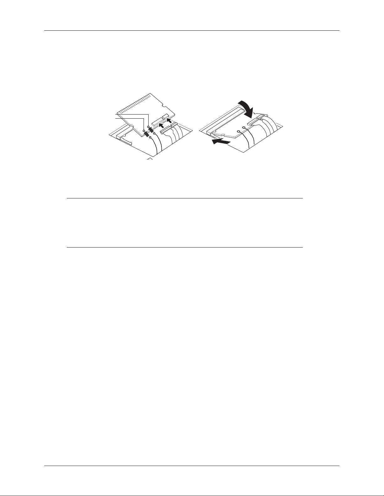
Installing the Mini PCI Adapter
For additional information on how to install and remove Mini PCI cards on your computer, see
the documentation provided with the computer. The following guidelines provide similar
instructions.
J1
J2
Danger:
AC adapter and remove the battery pack when opening the covers of the system or attached
devices.
Caution: After installing the Mini PCI card, do not turn the computer on until the
card cover has been closed and secured. Do not operate the computer with the card
cover open.
Grasp the card only by the sides that do not contain connectors. Avoid touching any
components or connectors on the card. Do not cut, tear, pierce or remove the
insulation tape on the card.
1. Do not remove protective coverings from the card.
2. Connect the two ribbon cables to the card.
3. Connect the two antenna cables to connectors J1 and J2 on the card (either cable can be
4. Position the card, with cables attached, at an angle of 20 to 30 degrees, with the contact edge
5. Push the card into the socket and lower the card into place.
6. Press down on both sides of the card until the two latches click into place in the half-circle
7. Close the Mini PCI card cover and tighten the screw
8. Replace the battery pack.
9. Turn the computer over, open the LCD panel and connect the AC adapter.
10. Power up the computer.
11. When you power up the computer, the Microsoft Windows Operating System will recognize
To avoid shock hazard when installing the Mini PCI card, disconnect all cables and the
insertion. Do not force the connections.
connected to J1 or J2).
Note
of the card aligned with the card slot (you may have to pull out the cables to achieve the
correct angle with the card).
positioned to prevent pinching or interference with card installation.
notches on each side of the card. The latches should be fully closed and the card firmly
secured.
unless the card cover is secured.
the new hardware. Insert the Xircom CD-ROM and follow the Windows instructions to
install the appropriate drivers for use with the Mini PCI adapter.
Section 1
The connectors are keyed for correct
Note:
Hardware Installation
: If there is only one antenna cable, connect it to J1.
Caution:
. Caution:
Be sure cables are
Do not turn on the computer
3
Xircom Inc. Mini PCI User’s Guide
Page 8

Hardware Installation
4
12. Configure your network and communications software as required (see your network
administrator for details).
Note: If prompted during software installation to choose between an older
file currently on your computer or a newer file supplied for the Mini PCI
adapter, choose to keep the older file.
Section 1
Mini PCI User’s Guide Xircom Inc
Page 9

This section describes how to install the software for the Mini PCI adapter.
Windows Installation
Use these instructions for a first-time installation of the Mini PCI adapter software drivers under
Windows 98SE, 2000, Me and NT4.0.
Turn on power to the computer and wait for Windows to start.
1
The adapter will be detected and the system will prompt for the location of driver files.
2
Insert the Xircom Installation CD and follow the Windows instructions to install the
3
appropriate drivers for use with the Mini PCI adapter. Verify the correct path to the disk, and
follow the prompts to complete the installation.
Windows will recognize the modem and driver files will be installed.
4
Section 2
Software Installation
5
SECTION 2
Software Installation
If prompted, remove the CD and reboot the system.
5
Proceed to
6
adapter.
Configuration Utility, Section
, for information about configuring the Mini PCI
2
Windows Modem Troubleshooting
Review this section if any of the following problems occur:
• Modem initialization errors occur when attempting to dial-out using a communications
application.
• The modem is not detected.
• Connection fails or other problems occur.
It may be necessary to define a modem type within your communications application. If the Xircom
modem is not listed, choose a “Generic Hayes compatible” device.
If your computer is equipped with an infrared communications port, you may need to disable this
port. These ports often use COM port resources required for other communications devices. Disable
the infrared port both in the computer’s CMOS or BIOS setup program and the Windows Device
Manager, as follows:
Some computers use a hardware setup utility to configure the infrared port in the BIOS. See
1
your computer documentation.
To disable the infrared communications port in Windows, go to Device Manager tab under
2
System in the Control Panel.
Double-click the Ports (COM & LPT) entry and the IR Serial Port entry. Remove the check
3
mark under Device Usage.
Xircom Inc. Mini PCI User’s Guide
Page 10

Software Installation
6
Section 2
Modem Diagnostics Tool
Use the modem diagnostics to verify the computer-to-modem interface.
In the Modems option in Control Panel, click Diagnostics.
1
In Diagnostics properties, highlight the COM port associated with the Xircom modem and click
2
the More Info button. This causes Windows to send commands to and read responses from the
modem and display information about the modem and its COM port. The Port Information box
should display the following information:
•
The IRQ and I/O address of the modem’s COM port. These should match the physical
configuration of the port or modem adapter.
•
Modem responses to various AT commands. The Xircom modem may return ERROR for some
AT commands that are not supported. This does not indicate a failure.
Windows NT 4.0 Modem Setup Installation
Use these instructions for a first-time installation of the Mini PCI adapter software drivers under
Windows NT 4.0.
Before the modem can be installed, a COM port must be installed. Do not reboot the computer
between adding the COM port and adding the modem.
Turn on power to the computer and wait for Windows NT to start.
1.
In the Control Panel, double-click the Ports icon.
2.
Add a new COM port (e.g. COM2 serial port) and use the default settings.
3.
Before you reboot the system, in the Control Panel, double-click the Modems icon.
4.
Install the modem on the COM port selected in step 3.
5.
When prompted for modem drivers, insert the disk containing the driver files, verify that the
6.
correct path to the disk, and follow the prompts to complete the installation.
After you install the modem, you will see
7.
Modems dialog of the Control Panel.
Finally, complete the installation by rebooting the computer.
8.
Xircom Wireless Ethernet Mini-PCI Adapter
in
Mini PCI User’s Guide Xircom Inc
Page 11

Section 3
Configuration Utility
Configuration Utility
This section described how to use the Configuration Utility for the Mini PCI adapter.
7
Section 3
Introduction
The WLAN Mini PCI adapter enables high-speed access to internet and intranet assets without wires.
This card uses the IEEE 802.11 protocol to enable communications between the host computer and
either another host computer or a network, using the 2.4GHz ISM Radio Band for the
communications medium. The host computer uses the adapter for communications in the same way
that it would use an Ethernet Network Interface Card (NIC).
The Configuration Utility is a Windows application that allows the user of a computer equipped with
a adapter to configure the adapter and to display the current configuration for the adapter.
Xircom Inc. Mini PCI User’s Guide
Page 12
Configuration Utility
8
Section 3
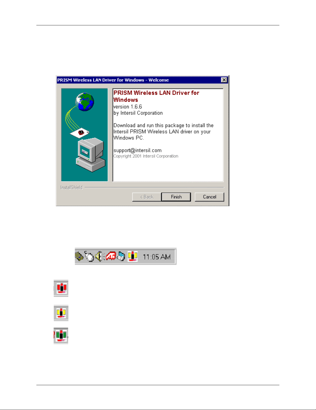
Installing the Configuration Utility
The Configuration Utility is installed simultaneously with the adapter driver by executing the
utility for the Windows.exe file. The following dialog shows the first dialog.
1. Click the
Finish button
to install the driver and the Configuration Utility on your computer
System Tray Icon
After the installation of the Configuration Utility, an icon appears in the System Tray in the
bottom right corner of your desktop.
The red, yellow and green colors of the icon indicate the link status.
Red indicates no or very poor link quality.
Yellow indicates a usable but weak link.
Green indicates a strong link.
Mini PCI User’s Guide Xircom Inc
Page 13

The status of the link can also be viewed by placing the cursor over the Configuration Utility
icon, as shown in the following illustration. This illustration indicates that the adapter is able to
communicate, but that the signal to the radio is weak.
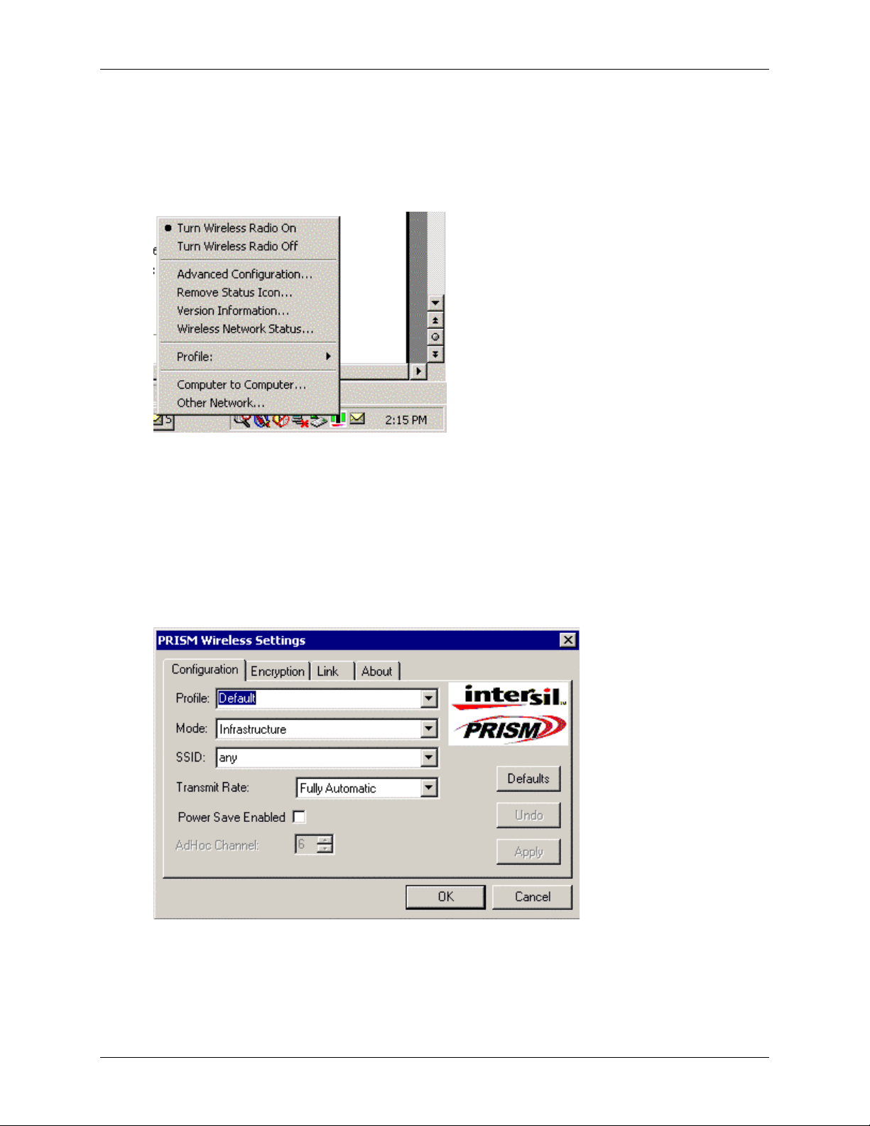
Icon Menu
Right-clicking on the System Tool Tray Icon displays a menu similar to the following illustration:
Section 3
Configuration Utility
9
The first two items in this menu let you turn the wireless radio on or off. Advanced
Configuration… launches the Configuration Utility application as discussed in the following
section. This lets you set configuration parameters that change the behavior of the adapter.
Remove Status Icon… removes the System Tray Icon. The driver continues to operate the card
in the last commanded configuration. The next time you power up your computer, the
configuration utility will return. You can also restart the Configuration Utility from the Start
Menu by selecting Programs and Configuration Utility.
Version Information…
launches the Configuration Utility with the About page selected,
giving the revision level of the driver, configuration utility and firmware.
Wireless Network Status…
launches the Configuration Utility with the Status page
selected. This shows the link status, including Signal Strength and Link Quality.
Profile:
lets you create, delete, and edit profiles. A profile is a named set of
configuration parameters that can be recalled.
Computer to Computer…
and Other Network… let you configure profiles for AdHoc
mode or Infrastructure Mode.
Xircom Inc. Mini PCI User’s Guide
Page 14
Configuration Utility
10
Section 3
Starting the Configuration Utility
You can launch the Configuration Utility either by double-clicking (with the left mouse button)
on the Configuration Utility icon or by right clicking on the Configuration Utility icon and
selecting Advanced Configuration…
If the Configuration Utility icon is not displayed in the System Tray, you can restart the
Configuration Utility from the Start Menu by selecting Programs and Configuration Utility.
The Configuration Utility consists of four menus: Configuration, Encryption, Link, and About.
The following sections describe these menus in detail.
Configuration Menu
The Configuration menu lets you specify the operating parameters for your adapter. When you
first start the Configuration Utility, this menu is displayed. If another menu is displayed, you can
display the Configuration menu by clicking on its tab in the Configuration Utility panel
.
Mini PCI User’s Guide Xircom Inc
Page 15
Setting the Profile
A profile is a named set of operating parameters for your adapter. The Profile field lets you set
values for all parameters by selecting a previously defined profile. Click the down arrow at the
right of the Profile field to display the available profiles for your adapter.
You will always have at least one profile, named Default. Initially, this profile contains the
parameters configured at installation. You can modify this profile at any time after the
installation. After changing parameters, you can save them in the profile named in this field by
clicking the Apply button in the Configuration Utility panel.
You can also create additional profiles by typing a name in the Profile field. When you change
the name in the Profile field and then click the Apply button, the Configuration Utility uses the
current parameters for your card to create a separate profile. You can then switch between
profiles by clicking the down arrow at the right of the Profile field, selecting a profile from the
drop-down list, and clicking the Apply button.
The following example describes a situation in which you would want to create multiple profiles.
Suppose that you use the wireless LAN at your work, but you also have a network in your home
(with a wireless Access Point) for sharing an internet connection and a printer between several
computers. Suppose also that you have another office within your business which also has
WLAN capability, but which is configured differently than your main office.
In this situation, you can create a different profile for each of these three environments. Each
profile specifies the parameters used on a single network. Moving from one location to another,
you only need to apply the appropriate profile to be able to participate in the local network.
Section 3
Configuration Utility
11
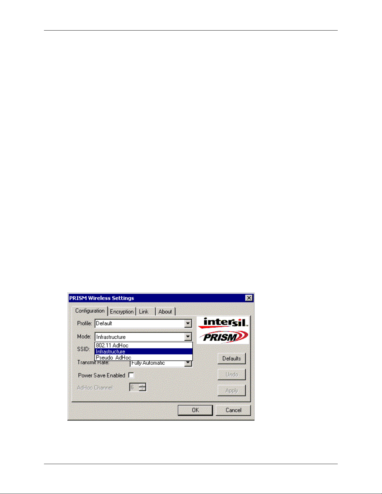
Setting the Mode
The adapter can operating in one of three modes, which are specified in the Mode field of the
Configuration menu. Clicking the down arrow at the right of the Mode field displays the
available modes
.
Xircom Inc. Mini PCI User’s Guide
Page 16

Configuration Utility
12
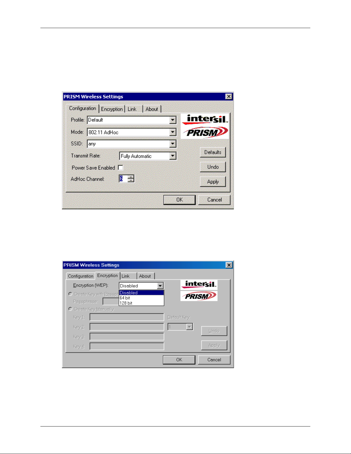
802.11 AdHoc Mode
IEEE 802.11, the standard on which the WLAN protocol is based, defines two modes to handle
two separate needs. The first, called AdHoc (or IBSS) mode, is used when two or more
wirelessly-enabled PCs wish to exchange data directly, without an Access Point. In this case the
PCs can establish an AdHoc network in which they are the only members and over which they
can exchange data. To exchange data, each computer participating in the AdHoc network must
also specify the same SSID and AdHoc Channel in this menu
Infrastructure Mode
The second mode defined by the IEEE 802.11 standard is called infrastructure mode, and is the
primary application for WLAN operation. In this mode all data on the wireless network is
directed to an Access Point, which then routes the data to the appropriate wireless station. The
Access Point may also be configured to allow data to be bridged from the wireless network to
wired networks.
To participate in a wireless LAN in infrastructure mode, every station and Access Point must
specify the same SSID. In infrastructure mode, all available channels are scanned for traffic, so
there is no need to specify a channel.
Pseudo AdHoc
Section 3
.
A third mode has been defined by Intersil, and is used mainly for testing purposes. Pseudo
AdHoc mode allows computers to communicate even without exchanging compatibility data. For
instance, you can send broadcast frames in this mode over a given channel and expect no
interruption by beacons or other packets not involved in the test. This mode can be used for
Packet Error Rate Testing, for example, to evaluate performance.
As with AdHoc mode, each computer participating in the Pseudo AdHoc network must also
specify the same SSID and AdHoc Channel in this menu. However, note that this mode can only
be used to communicate with other adapter.
Setting the SSID
The SSID is the Service Set IDentifier used by Access Points and stations to identify a wireless
LAN. Your PRISM WLAN Interface card scans the available channels looking for an Access
Point (in infrastructure mode) or another station (in AdHoc mode) which has specified this same
SSID. It then attempts to associate with these Access Points or stations to form a wireless LAN.
To change the SSID, simply highlight it, type the new SSID, and click the Apply button.
In typical infrastructure applications a company will use a single SSID for all Access Points. If
the radio is scanning and cannot find a channel when an Access Point is known to be in range,
verify that the SSID is set correctly.
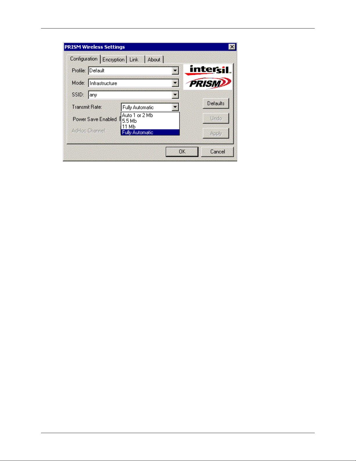
Setting the Transmit Rate
The Transmit Rate field specifies the rate at which the radio in your adapter’s transmits and
receives data. You can view the available rates by clicking the down arrow at the right of the
Transmit Rate field.
Mini PCI User’s Guide Xircom Inc
Page 17
Section 3
Configuration Utility
13
The transmit rate can be set to:
•
Fully Automatic – your adapter chooses the highest available rate providing reliable
communications based on the capabilities of the Access Point or station with which it
communicates and on the received signal quality
•
Auto 1 or 2 Mb – allows only 1 and 2 Mb/s operation
•
5.5 Mb – allows only 5.5 Mb/s operation
•
11 Mb – allows only 11Mb/s operation
To change the Transmit Rate, click the down arrow at the right of the field, highlight the rate you
want to set, and click the Apply button.
Under most conditions, you should choose Fully Automatic as the transmit rate. In general, fixed
rates are used only in test environments.
Enabling Power Save Mode
The IEEE 802.11 standard provides a Power Save Mode. In this mode your adapter listens for a
beacon (a periodic frame which defines the network type and attributes) and determines the
beacon interval. Between beacons the card puts itself to sleep, enabling power savings. At the
time of the expected beacon the card wakes itself up and receives the beacon. The received
beacon contains information about whether the Access Point or station has buffered frames for
the card. If frames are available the card requests those frames until no more frames are
available. The card then goes back to sleep until the next beacon.
For Access Points that support power save mode and for stations equipped with WLAN cards,
enabling this mode can significantly reduce power consumption, which is particularly important
if the host computer is operating on battery power. However, be aware that power save mode
also results in lowered transmission and reception speed on the wireless LAN.
Xircom Inc. Mini PCI User’s Guide
Page 18
Configuration Utility
14
Section 3
Selecting the Ad Hoc Channel
When communicating in AdHoc or Pseudo AdHoc mode, you must specify a channel on which
communications will take place. To specify a channel, click the up or down arrow at the right of
the AdHoc Channel field until the channel you want to set appears, and then click the Apply
button
.
This field is grayed in infrastructure mode because the channel is automatically selected by the Access
Point.
Encryption Menu
The Encryption menu lets you enable encryption and set the encryption keys. To see the available
encryption methods, click the down arrow at the right of the Encryption {WEP} field
There are two encryption methods available. The IEEE 802.11 specification defines Wired
Equivalent Privacy (WEP) using a 64-bit key. This capability was extended by the industry to
allow a 128 bit key.
.
If you specify an encryption method, you will only be able to communicate with Access Points
and stations that use the same encryption method and keys.
Mini PCI User’s Guide Xircom Inc
Page 19
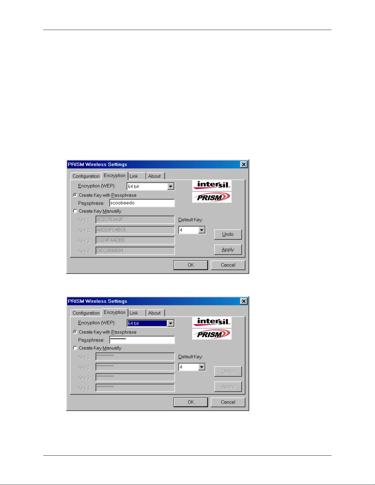
Disabling Encryption
To disable encryption, click the down arrow at the right of the Encryption field, select Disabled,
and click the Apply button.
Enabling Encryption
To enable encryption, click the down arrow at the right of the Encryption field, select either 64 bit
or 128 bit, and click the Apply button. After enabling an encryption method, you must then
specify encryption keys, as described in the following sections.
Creating Encryption Keys Using a Passphrase
To create encryption keys using a passphrase, click the radio button next to Create Key with
Passphrase and type a character string in the Passphrase field. As you type, the Configuration
Utility uses an algorithm to generate four keys used for encryption
Section 3
.
Configuration Utility
15
When you finish typing your character string and click the Apply button, the Configuration
Utility uses asterisks to mask both your passphrase and the keys it generates
.
Using a passphrase to generate the four keys makes it easy to set the same keys for all members
of your wireless LAN
.
Xircom Inc. Mini PCI User’s Guide
Page 20
Configuration Utility
16
Section 3
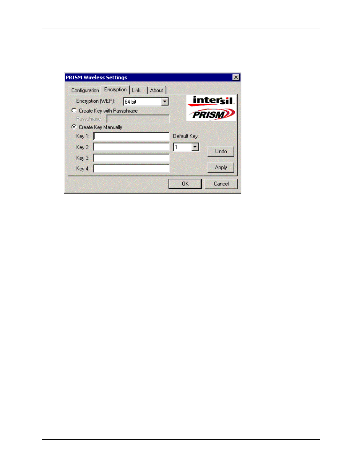
Creating Encryption Keys Manually
If you want, you can create encryption keys manually by clicking the radio button next to Create
Key Manually, as shown in the following illustration.
When you click this button, the cursor appears in the field for Key 1. For 64-bit encryption, you
must type
must type
encryption keys. After you click the Apply button, the Configuration Utility uses asterisks to
mask your keys.
Default Key
The Default Key field lets you specify which of the four encryption keys you use to transmit data
on your wireless LAN. You can change the default key by clicking on the down arrow at the
right of this field, selecting the number of the key you want to use, and then clicking the Apply
button. As long as the Access Point or station with which you are communicating has the same
key in the same position, you can use any of the keys as the default.
exactly
exactly
10 hexadecimal digits in each of the four key fields; for 128-bit encryption, you
26 hexadecimal digits. You then click the Apply button to create your
Mini PCI User’s Guide Xircom Inc
Page 21
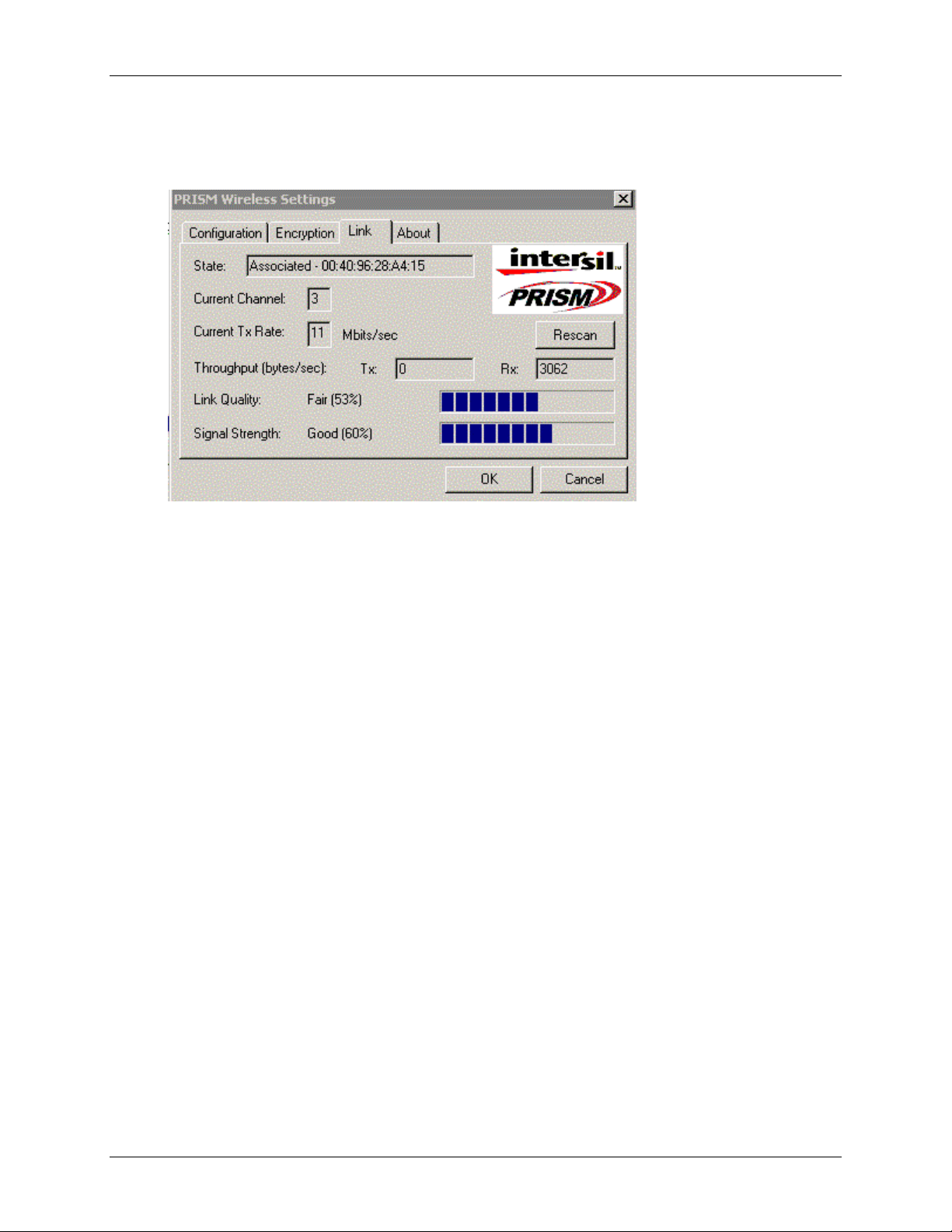
Link Menu
The Link menu provides information on the status of your communications with the wireless
LAN
.
The fields in this menu provide the following information:
Section 3
Configuration Utility
17
•
State: shows the association state of your computer with the wireless LAN. The
above illustration shows that your computer is associated with an Access Point and
gives the Access Point’s MAC address.
•
Current Channel: shows the channel on which the connection is made. In
Infrastructure mode, this number changes as the radio scans the available channels.
•
Current Tx Rate: shows the highest transmit rate of the current association.
•
Throughput: shows the short term transmit and receive throughput in bytes/second
continuously updated.
•
Link Quality: is based on the quality of the received signal of the Access Point
beacon.
•
Signal Strength: is based on the received signal strength measurement of the
baseband processor of the Beacon signal.
You can click the Rescan button to force the radio to rescan all available channels. If your link
quality or signal strength is poor, rescanning can be used to push the radio off a weak Access
Point and search for a better link with another Access Point.
Xircom Inc. Mini PCI User’s Guide
Page 22

Configuration Utility
18
About Menu
The About menu provides information on the version of the Network Driver, the Configuration
Utility, and the firmware in the adapter. In addition, this menu also provides the MAC address of
the adapter.
Section 3
Mini PCI User’s Guide Xircom Inc
Page 23

Appendix A
Modem AT Commands
19
Appendix A
Modem AT Commands
This section provides the following information:
•
Introduction to Modem AT Commands
•
Special Commands
•
AT Command Reference
Introduction to Modem AT Commands
Modem AT Commands With the exception of the Special Commands, all commands must be preceded by
the AT attention code (or command prefix) and terminated by pressing the
The modem responds with the result code OK, which means it understands and can execute the command,
or with
invalid.
ERROR
, which means that the modem does not understand the command or that the command is
Enter
key.
The modem must be in command mode when any command other than the online escape sequence is
entered. Commands entered when the modem is in online mode are treated as data and transmitted as such
to the modem at the other end of the line.
Some commands are used in coordination with S-Registers.
Special Commands
+++ Online Escape Sequence
The escape sequence is used to switch to command mode from online mode during a session with a
remote modem. Type three "plus signs." The escape sequence is not preceded by the AT command prefix,
nor does it require the Enter key. The setting of S-Register S2 determines the ASCII character used.
S2=43 is the default (the "+" sign). 0-127 are valid. To disable the command, set S2 to a value greater
than 127. Use the
Insert a pause before and after the escape sequence to prevent misinterpretation of the escape sequence as
data. Use S-Register S12 to set the length of the pause.
A/ Repeat Last Command
The A/ command causes the modem to repeat the last command string. The command executes as soon as
is typed. It does not require the AT command line prefix, nor does it need to be followed by Enter.
/
("AT" and letter "O") command to return to online mode.
ATO
Xircom Inc. Mini PCI User’s Guide
Page 24

Modem AT Commands
20
Appendix A
AT Command Reference
A Answer
Typing
signal and starting the handshaking process. This must be the only command or the final command in the
command line.
causes the modem to go off-hook and respond to an incoming call by generating a carrier
ATA
If the handshaking process is successful and a connection is established, the normal
CONNECT
is displayed. If the carrier signal is not detected within the time specified in S-Register S7, a
CARRIER
Bn Select Communications Standard
The
result code is displayed.
command selects the communication standard (ITU or Bell) to be used by the modem, as
ATBn
message
NO
follows:
B0 Use ITU V.22 at 1200bps. B0 selects ITU V.22 at 1200bps and ITU V.21 at 300bps.
B1 Use Bell 212A at 1200bps. B1 selects Bell 212A at 1200bps and Bell 103J at 300bps.
B2 Unselect V.23 reverse channel.
B3 Select V.23 reverse channel.
B15 Selects V.21 when the modem is at 300bps (same as B0).
B16 Selects Bell103J when the modem is at 300bps (same as B1).
The ATB1 and ATB16 parameter settings are not available in some countries. Defaults are country-specific.
Break (Escape) command
Cn Carrier Control
The ATCn command, where n is 1, guarantees backward compatibility with communications software that issues the
C1 command. C0 is not supported; it may set some modems to "receive only mode."
C0
C1
Dn Dial A Telephone Number
string consisting of dial digits/characters and dial modifiers (see below) and must not exceed 40 characters. Spaces,
hyphens, and parentheses can be used for clarity, but they are ignored by the modem.
Transmit carrier always off (
Normal transmit carrier switching.
See Special Commands.
not supported
The ATDn command is used to dial a telephone number. The n represents a dial
).
The Dial command can be used for either pulse (rotary) or tone dialing. The dial digits/characters
are 0 - 9 A B C D # *. The characters A B C D and the symbols # and * represent specific tone
pairs and can be used only when tone dialing. These characters and symbols are ignored when
pulse dialing is used. Some countries restrict or prohibit the use of some of these characters.
Dial Modifiers
Dial modifiers are recognized by the modem only when they are part of a dial string following
the ATD command. Possible dial modifiers are:
L Redial Last Number
Redials last number if used as first character following ATD. Otherwise it is ignored.
Mini PCI User’s Guide Xircom Inc
Page 25

Appendix A
Modem AT Commands
21
P Pulse Dialing Method
The P modifier is used with the Dial command to instruct the modem to pulse dial the telephone
number that follows.
S=n Dial a Stored Telephone Number
The S modifier instructs the modem to dial a number that had been previously stored by the use
of the AT&Zn=x command. The command to dial a stored telephone number is ATDS=n, where
n represents telephone number storage location 0 or 1. For example, ATD P S=1 pulse dials the
telephone number written to telephone number storage location 1.
, Delay Processing the Next Character
When the comma (,) modifier is included as part of the dial string following the ATD command,
the modem pauses before processing the next character in the dial string. The duration of the
pause is dictated by the contents of S-Register S8.
The , modifier is frequently inserted after the digit (usually 9) used to obtain an outside line from
a PBX to allow sufficient time for the dial tone to occur before the modem dials the telephone
number. The W modifier can be used in place of the comma.
Some countries place restrictions on the amount of time a modem may delay during dialing.
T Tone Dialing Method
The T modifier is used with the Dial command to instruct the modem to tone dial the telephone
number that follows. See also the ATT command.
W Wait for Second Dial Tone
The W modifier instructs the modem to wait for a dial tone before processing the remaining
characters in the dial string.
! Hook Flash
The ! modifier serves as a switch hook (or hook flash) signal. This causes the modem to hang up
(go on-hook) for about 0.5 seconds then return to off-hook (the actual duration of the hook flash
varies in different countries).
@ Wait for Quiet Answer
The @ modifier in a dial string instructs the modem to wait for five seconds of silence after
dialing the number. If silence is not detected, the modem sends a NO ANSWER result code to
the user.
; Return to Command Mode after Dialing
The semicolon (;) dial modifier can be used only at the end of a command line, immediately
preceding the Enter, and instructs the modem to return to the command mode immediately after
dialing and without breaking the connection with the distant modem.
Xircom Inc. Mini PCI User’s Guide
Page 26

Modem AT Commands
22
Appendix A
^ Disable Data Calling Tone Transmission
The ^ modifier in a dial string disables data calling tone for the current call (calling tone is
automatically enabled in many countries). This modifier is not available in all countries.
$ Credit Card Tone Detect
The $ modifier in a dial string instructs the modem to wait for a credit card "bong" tone before
processing the remaining characters in the dial string.
En Echo Command
The ATEn command, where n represents 0 or 1, determines if the commands you issue through
the keyboard to the modem in command mode are displayed (echoed) on your computer's
monitor screen.
E0
E1
Disable echo to the computer.
Enable echo to the computer (default).
If the commands you type are not displayed on your monitor screen, your software is set to
expect character echo from the remote system. You can remedy this by typing in the command
ATE1. If the commands you type are displayed on your monitor with the characters duplicated,
LLIIKKEETTHHIISS
Hn Switch Hook Options
, type in the ATE0 command.
The ATHn command hangs up the modem or prepares it for dialing.
Causes the modem to go on-hook (default).
ATH0
ATH1 Causes the modem to go off-hook (this command is restricted in some countries).
In Request ID Information
The ATI command has various options which are used to instruct the modem to provide specific
information about itself.
I0 Displays modem controller firmware revision (same as I3).
I1 Calculates ROM checksum and displays it on the DTE (for example, 12AB).
I2 Performs a ROM check and calculates and verifies the checksum. displaying OK or ERROR..
I3 Displays modem firmware revision information.
I12 Returns country code (for example, North America).
Ln Monitor Speaker Volume
The ATLn command, where n represents 0, 1, 2, or 3, is listed here for backward compatibility
reference only. The volume of the monitor speaker is controlled by the computer, not by the
modem.
Mini PCI User’s Guide Xircom Inc
Page 27

Modem AT Commands
23
Mn Speaker On/Off Selection
Appendix A
The ATMn command, where n represents 0, 1, 2, or 3, enables or disables the transmission of
sound signals from the modem to the computer speaker. (Sound production also requires that the
computer speaker be enabled.)
M0 Speaker always off.
Speaker on until data carrier is detected.
M1
M2 Speaker always on when modem is off-hook.
M3 Speaker off as digits are dialed, then on after dialing until data carrier is detected.
Nn Negotiation of Handshaking Options
The ATNn command, where n represents 0 or 1, determines whether or not the sending modem
performs a negotiated handshake when the speed of the answering modem is different from that
of the sending modem.
When originating or answering, handshake only at the communication standard specified by the contents of S-
N0
Register
When originating or answering, handshake only at the communication standard specified by the contents of SRegister
N1
required (default).
On Online Command
S37
S37
and the
and the
command option selected.
ATBn
command option selected. During handshaking, fall back to a lower speed, if
ATBn
If the modem has been switched to command mode, typing in the ATO0 command will return it
to the online mode with the existing connection.
Instructs modem to leave online command mode and return to data mode (see +++ Escape Sequence under
O0
Special Commands).
O1 This setting issues a retrain command before returning to online data mode.
O2 This setting issues a rate negotiation command before returning to online data mode.
P Select Pulse Dialing
The ATP command instructs the modem to use pulse (rotary) dialing. This mode will remain in
force for all dialing procedures unless an ATT command is issued or the dial string contains a T
dial modifier.
Qn Result Code Display Options
The setting of the ATQn command, where n represents 0 or 1, determines whether or not result
codes (such as OK, CONNECT, RING, NO CARRIER, and ERROR) are displayed on your PC's
screen.
Q0
Q1
Xircom Inc. Mini PCI User’s Guide
Display of result codes enabled.
Display of result codes disabled.
Page 28

Modem AT Commands
24
Repeat command
Appendix A
See Special Commands.
T Select Tone Dialing
The ATT command instructs the modem to use tone dialing. This mode will remain in force for
all dialing procedures unless an ATP command is issued or the dial string contains a P dial
modifier. Tone dialing is the factory-default setting.
Vn Result Code Format Options
The ATVn command, where n represents 0 or 1, determines if result codes are displayed as
numeric (short form) codes or words (long form). Numeric result codes contain only one or two
digits and this form could be used, for example, when the modem is controlled by a software
terminal emulation program that uses script files. See the list at the beginning of this topic
showing result codes in both long and short formats.
Type the command ATV or ATV0 to select numeric result codes. The factory default is to
display the result codes as words (ATV1). You should issue an ATV1 command either to reset
the factory default after a change has been made or to select the long-form (word) result codes.
Negotiation progress messages (extended result codes) are those with a numerical value of 40 or
more.
Four other AT commands, two dial modifiers, and an S-Register are also directly involved in the
generation and display of result codes. These are the ATQn, ATVn, ATWn, and ATXn
commands, the ATDW and ATD@ dial modifiers, and S-Register S95.
Wn Negotiation Progress Message Selection
The ATWn command, where n represents 0, 1, or 2, works in conjunction with S-Register S95 to
determine how that subset of the result codes - called negotiation progress messages or extended
result codes - will be used to report the type of connection, protocol, and other communication
techniques that resulted from handshaking and subsequent negotiation.
The options available to represent n in the ATWn command are:
CONNECT result code reports DTE speed. If S-Register S95=0, disable the display of all extended result
W0
codes.
CONNECT result code reports DTE speed. If S-Register S95=0, enable the display of CARRIER and
W1
PROTOCOL extended result codes only.
CONNECT result code reports DCE (modem-to-modem) speed. If S-Register S95=0, disable the display of all
W2
extended result codes.
Mini PCI User’s Guide Xircom Inc
Page 29

Appendix A
Modem AT Commands
25
Xn Result Code Set/Call Progress Option
The ATXn command, where n represents 0-4, controls how the modem responds to dial tone and
busy signals and how it displays CONNECT result codes. The options available to specify with
the ATXn command are:
X0 Result codes 0-4 enabled. Busy detect and dial tone detect disabled.
X1 Result codes 0-5, and 10 enabled. Busy detect and dial tone detect disabled.
X2 Result codes 0-6, and 10 enabled. Busy detect disabled and dial tone detect enabled.
X3 Result codes 0-5, 7, and 10 enabled. Busy detect enabled and dial tone detect disabled.
Result codes 0-7, and 10 enabled. Busy detect and dial tone detect enabled.
X4
Caution: Some countries do not allow busy detect or dial tone detect to be disabled.
Yn Long Space Disconnect Option
The ATYn command, where n represents 0 or 1, determines whether or not the modem will
disconnect a call when it receives a long space (1.6 seconds Break) signal during a V.22bis
connection.
Disables the long space disconnect facility (supported for backward compatibility
Y0
reference only).
Y1 Enables the long space disconnect facility (
Zn Recall Stored Profile
not supported
).
The ATZn command, where n represents 0, disconnects any call that is currently in progress and
reloads the user configuration profile stored in nonvolatile memory as the active configuration
profile.
Disconnect and reload the profile contained in storage location 0 as the active
Z0
configuration profile.
&Bn V.32 Automatic Retrain Options
The Xircom modem always retrains. The automatic retrain feature cannot be disabled.
&B0 Disables the V.32 automatic retrain capability (not supported).
Enables the V.32 automatic retrain capability (supported for backward
&B1
compatibility only).
Xircom Inc. Mini PCI User’s Guide
Page 30

Modem AT Commands
26
Appendix A
&Cn Data Carrier Detect (DCD)
The AT&Cn command, where n represents 0 or 1, selects the method by which the modem
handles the carrier detect signal.
The carrier detect signal is forced on regardless of the condition of the distant
&C0
modem's carrier.
The state of the carrier from the remote modem is monitored. The local modem's
DCD signal is on when the remote modem's carrier signal is detected, and off
&C1
when it is not (default).
&Dn Data Terminal Ready (DTR) Options
The AT&Dn command, where n represents 0-3, controls how the Data Terminal Ready (DTR)
signal is used by the modem.
&D0 Ignore the DTR signal from the computer and treat it as always on.
Monitor DTR and, when an ON-to-OFF transition of the DTR signal occurs,
&D1
switch to command mode, issue an OK result code, and remain connected.
Monitor DTR and, when an ON-to-OFF transition of the DTR signal occurs,
&D2
hang up the line and switch to command mode.
Monitor DTR and, when an ON-to-OFF transition of the DTR signal occurs,
&D3
hang up, reset the modem and switch to the initialization state.
&Fn Load Factory Settings
The AT&F command loads factory default parameters from ROM into the active configuration
profile, replacing the parameters stored there. This command must be issued by itself. If it is
used with another AT command, its function will be ignored.
&F0 Recall factory settings as active configuration.
Recall factory settings appropriate for ETC mode as active configuration. This
&F5
command enables ETC operation. It is automatically set upon detection of a
cellular phone. The following options are set with &F5:
Local Factory Settings
Function
LAPM-only error correction
Transmit level fixed per cellular phone
Wait for carrier = 90 sec
CD loss delay = 10 sec
Auto FF/FB enabled
Start up at 9600bps
MTC Implementation
\N4
S92
S7=90
S10=100
N/A
S40=2
Mini PCI User’s Guide Xircom Inc
Page 31

Appendix A
Modem AT Commands
27
&Gn V.22bis Guard Tone Selection
This option is for international use only. It is not used in North America. The AT&Gn
determines which guard tone, if any, to transmit while in answer mode (transmitting in the high
band). The value of n can be 0, 1, or 2. This parameter is set automatically for most countries
that require it.
No guard tone set.
&G0
&G1
&G2
&Jn Auxiliary Relay Option
&J0
&J1
&Kn Local Flow Control Options
Enable RTS/CTS flow control (default).
1800-Hz guard tone set.
Auxiliary relay is never closed.
Not supported (returns ERROR).
The AT&Kn command, where n represents 0-4, determines how the flow control between the
computer and the local modem is handled.
&K0
&K3
&K4
&Mn Communications Mode
Disable local flow control.
Enable RTS/CTS flow control (default).
Enable XON/XOFF flow control.
The AT&Mn command, where n represents 0-4, determines how the flow control between the
computer and the local modem is handled.
Asynchronous mode (default; supplied for backward compatibility only).
&M0
&Pn Pulse Dial Make-to-Break Ratio Selection
The AT&Pn command, where n represents 0, 1, or 2, controls the ratio of the off-hook (make) to
on-hook (break) interval used by the modem when it pulse dials.
Selects 39:61 make/break ratio at 10 pps (default - U.S.).
&P0
&P1 Selects 33:67 make/break ratio at 10 pps (default - Japan).
&P2 Selects 33:67 make/break ratio at 20 pps (option - Japan).
&Qn Asynchronous Communications Mode
&Q0 Asynchronous mode, buffered (same as \N0).
&Q5 Error control mode, buffered (default; same as \N3).
Asynchronous mode, buffered (same as \N0).
&Q6
Xircom Inc. Mini PCI User’s Guide
Page 32

Modem AT Commands
28
&Sn Data Set Ready (DSR) Options
Appendix A
The AT&Sn command controls the functions of the modem's DSR circuits.
The DSR signal remains on all the time the modem is powered on (default).
&S0
&S1 The DSR signal is on during handshaking and is off when carrier is lost.
&Tn Self-Test Commands
The AT&Tn command allows the user to perform diagnostic tests on the modem.
Abort. Stops any test in progress.
&T0
Local analog loop. this test verifies modem operation, as well as the connection
&T1
between the modem and computer. The modem must be off-line when this test is
run.
&T3 Local digital loopback test.
Remote digital loopback test. This test can verify the integrity of the local
&T6
modem, the communications link, and the remote modem. The modems must be
online with error control disabled when this test is run.
&V View Configuration Profile
The AT&V command displays the contents of the active configuration profile.
&Wn Write Active Profile to Memory
The AT&Wn command, where n is 0, allows you to save a copy of the current active
configuration profile to nonvolatile memory. This profile can be restored at any time by using the
ATZ command or a power-up reset of the modem.
&Yn Select Stored Profile for Hard Reset
This command is included for compatibility with applications that use the &Y0 command. It
does not affect the behavior of the modem.
&Y0
&Y1
&Zn=x Store Telephone Number
Select stored profile 0 on power up.
Not supported, returns ERROR.
The AT&Zn=x command is used to store a telephone number for later dialing using the ATDS=n
(dial stored number) command. In this command, n is 0 or 1 representing 2 storage locations and
x is the stored number. The dial string may contain up to 40 characters.
Mini PCI User’s Guide Xircom Inc
Page 33

Appendix A
Modem AT Commands
29
\Gn Modem Port Flow Control
The AT\Gn command determines whether XON/XOFF flow control will be used.
Returns OK for compatibility (default).
\G0
\G1
\Jn Adjust BPS Rate Control
\J0
\J1
\Kn Break Control
Not supported; returns ERROR.
Turn off feature (default).
Turn on feature.
The AT\Kn command determines how the modem processes a Break signal received from the
local DTE during a connection (online).
Modem sends Break to remote modem in sequence with transmitted data,
\K5
nondestructive/nonexpedited (default).
\Nn Error Mode Control Selection
The AT\Nn command sets the type of error correction supported by the modem when sending or
receiving data.
\N0 Buffered mode. No error control (same as &Q6).
\N1 Buffered mode (same as \N0).
\N2 LAPM, MNP or disconnect mode. This is also known as reliable mode.
LAPM, MNP, or buffered (default). The modem attempts to connect in LAPM
error control mode. If this fails, the modem attempts to connect in MNP mode. If
\N3
this fails, the modem connects in buffered mode and continues operation. This is
also known as V.42 auto-reliable mode (same as &Q5).
LAPM or disconnect. The modem attempts to connect in LAPM error control
\N4
mode. If this fails, the call will be disconnected.
MNP or disconnect mode. The modem attempts to connect using MNP 2-4 error
\N5
control procedures. If this fails, the modem disconnects. This is also known as
MNP reliable mode.
\Qn Local Flow Control Selection
The AT\Qn command sets the type of flow control used on the serial port to adjust for
differences in modem port speed.
\Q0 Disables flow control (same as &K0).
\Q1 Sets flow control to XON/XOFF (same as &K4).
RTS/CTS to DTE (default; same as &K3).
\Q3
Xircom Inc. Mini PCI User’s Guide
Page 34

Modem AT Commands
30
Appendix A
\Tn Inactivity Timer Limit
The AT\Tn command specifies length of time (in minutes) that the modem waits before
disconnecting when no data is sent or received. The time period can be set at n = 0 - 255. A
setting of zero disables the timer. As an alternative, the timer may be specified in S-Register S30.
This function is only applicable in buffer mode.
\Xn XON/XOFF Pass Through
Modem process XON/XOFF flow control characters locally (default).
\X0
\X1 Not supported; returns ERROR.
%B View Numbers in Blacklist
If blacklisting is in effect, the AT%B command displays the numbers for which the last call
attempted in the past two hours failed. In countries that do not require blacklisting, this command
returns ERROR.
%Cn Data Compression Control
The AT%Cn command determines the operation of V.42bis and MNP class 5 data compression.
Online changes do not take effect until a disconnect occurs.
%C0 V.42bis/MNP Class 5 compression disabled (no data compression).
%C1 MNP Class 5 compression enabled (no V.42bis).
%C2 V.42bis compression enabled (no MNP Class 5).
V.42bis/MNP Class 5 data compression enabled (default).
%C3
-Cn Data Calling Tone
Data calling tone is a tone of a certain frequency and cadence specified in V.25 that allows
remotes data/fax/voice discrimination. The frequency is 1300 Hz with a cadence of 0.5 seconds
on and 2 seconds off.
-
Disables calling tone (default).
C0
Enables calling tone.
C1
Caution:
+GCAP Request Complete Capabilities List Syntax:
Syntax:
Some countries do not permit calling tone to be disabled.
AT+GCAP
AT+GCAP=?
Mini PCI User’s Guide Xircom Inc
Page 35

Appendix A
Modem AT Commands
This command displays one or more lines of information text, in a standard format, describing
the basic capabilities of the modem. This allows a software package to determine which groups
of extended-syntax commands the modem supports. The response may contain one or more of
the following responses:
31
+CGSM
+DS
+ES
+FCLASS
+MS
+W
GSM (+C) commands.
Data Compression (+D) commands.
Error Control (+E) commands.
Fax (+F) commands.
Modulation Control (+M) commands.
Wireless (+W) commands.
+GCAP=? may be used to determine whether the modem supports the +GCAP command: an OK
response indicates support, ERROR indicates non-implementation.
+GCI Country of Installation
Syntax:
AT+GCI=<T.35 code>
AT+GCI?
AT+GCI=?
This command configures the modem for the country of use, selecting operational parameters
and ensuring conformity to the requirements of the selected country's telephone network. The
+GCI parameter may only be changed when the modem is in an idle state.
Note 1:
The Xircom CountrySelect utility is recommended for setting country parameters for
modem calls. The CountrySelect utility is accessible after installation at Start, Programs, Xircom
Utilities.
Note 2:
To determine what countries are supported by your Xircom modem product, run the
Xircom CountrySelect utility using Start, Run, Xircom Utilities, CountrySelect, or use the
command AT+CGI=?. The AT+CGI=? command will respond with the T.35 codes for the
countries supported. The list of <T.35> codes below includes countries supported by this
product at time of publication, but not all countries listed are supported by this product.
Xircom Inc. Mini PCI User’s Guide
Page 36

Modem AT Commands
32
Appendix A
Caution:
other country setting for calls originating in Japan is a violation of local law.
For units sold in Japan, Japan has been set as the default country setting. Use of any
To change the current country selection, use AT+GCI=<T.35 code> (but see Notes 1 and 2
above).
Country
Argentina
Australia
Austria
Barbados
Belgium
Brazil
Canada
China
<T.35 code>
07
09
0A
0E
0F
16
20
26
Country
Mexico
Netherlands
New Zealand
Norway
Panama
Philippines
Poland
Portugal
<T.35 code>
73
7B
7E
82
85
89
8A
8B
Czech Republic 2E
Denmark
Finland
France
Germany
Greece
Guam
Hong Kong
Hungary
Iceland
India
Indonesia
Ireland
31
3C
3D
04
46
48
50
51
52
53
54
57
Puerto Rico
Russia
Singapore
Slovakia
Slovenia
South Africa
South Korea
Spain
Sweden
Switzerland
Taiwan
Thailand
Turkey
8C
B8
9C
FC
FB
9F
61
A0
A5
A6
FE
A9
AE
Israel
Mini PCI User’s Guide Xircom Inc
58
United Kingdom
B4
Page 37

Appendix A
Modem AT Commands
33
Italy
Japan
Kuwait
Liechtenstein
Luxembourg
Malaysia
+GMI Request Manufacturer Identification
Syntax:
59
00
C2
68
69
6C
AT+GMI
AT+GMI=?
United States
Universal
United Arab Emirates B3
US Virgin Islands FA
Venezuela
Vietnam
B5
FD
BB
BC
This command displays one or more lines of information text, identifying the manufacturer of
the modem. +GMI=? may be used to determine whether the adapter supports the +GMI
command: an OK response indicates support, ERROR indicates non-implementation.
+GMM Request Model Identification Syntax:
Syntax:
AT+GMM
AT+GMM=?
This command displays one or more lines of information text, identifying the modem model.
+GMM=? may be used to determine whether the modem supports the +GMM command: an OK
response indicates support, ERROR indicates non-implementation.
+GMR Request Revision Identification Syntax:
Syntax:
AT+GMR
AT+GMR=?
This command displays one or more lines of information text, identifying the revision level of
the firmware of the modem. +GMR=? may be used to determine whether the adapter supports
the +GMR command: an OK response indicates support, ERROR indicates non-implementation.
+MS Modulation Selection
Caution: The AT+MS command is not applicable under the V.90 standard for 56K modems.
To set V.90 operation, see S-Register S109.
The AT+MS parameter controls data modulations and bit rates that may be negotiated between a
local and remote modem. It accepts four subparameters.
Xircom Inc. Mini PCI User’s Guide
Page 38

Modem AT Commands
34
Appendix A
AT+MS=<carrier>,<automode>,<min_rate>,<max_rate>
Syntax:
+MS?
+MS=?
<carrier>
<automode> Enables or disables negotiation of an alternative <carrier> if the preferred modulation is not available.
<min_rate>
<max_rate>
AT+MS?
AT+MS=?
Reports the current settings of subparameters
Displays range of acceptable values for each subparameter
Specifies the preferred modulation to be used in originating or answering a connection. The <carrier>
subparameter is an unquoted string of characters. If the <carrier> parameter is specified, the other
subparameters will revert to factory defaults. If <carrier> is omitted, any unspecified parameters will
keep their current values (for example, AT+MS=,0 or AT+MS=,,,2400).
Values accepted for <carrier> are the following:
B103 Bell 103 (300bps)
B212 Bell 212A (1200bps)
V21 ITU-T V.21 (300bps)
V22 ITU-T V.22 (1200bps)
V22B ITU-T V.22bis (2400bps)
V23C ITU-T V.23 with constant carrier (1200/75 or 75/1200bps)
V32 ITU-T V.32 (4800 or 9600bps)
V32B ITU-T V.32bis (4800 - 19200bps)
V34 ITU-T V.34 (2400 - 33600bps)
Lucent/Rockwell K56flex (32000 - 56000bps). Not applicable under the V.90 standard. To set
K56
V.90, see S-Register S109.
Values accepted for <automode> are the following:
0 Disabled. Modem will disconnect if it is unable to negotiate a connection with the specified
<carrier>.
Enabled (default). If the specified <carrier> is unavailable, modem will attempt to negotiate an
1
alternative carrier as appropriate.
Specifies the lowest bit rate at which the modem may establish a connection. (This value is fixed at
zero for the Xircom modem.)
Specifies the highest bit rate at which the modem may establish a connection. For modulations that
support only a fixed bit rate (such as V.22bis), <max_rate> has a fixed value to which it defaults. If the
default rate or a rate other than zero is specified, the modem will return ERROR. This subparameter
accepts the following values: 0, 300, 1200, 2400, 4800, 7200, 9600, 12000, 14400, 16800, 19200,
21600, 24000, 31200, 33600bps. If unspecified (set to 0), <max_rate> is determined by the value of
<carrier>.
If the <carrier> setting is K56, the <max_rate> subparameter should be left at the default value (zero).
Mini PCI User’s Guide Xircom Inc
Page 39

Appendix A
Modem AT Commands
35
Modem S-Registers
This section provides the following information:
Introduction to S-Registers
S-Register Reference
Introduction to S-Registers
The Xircom modem uses memory storage locations, or S-Registers, to hold information
controlling its operating environment. Few of these S-Registers require attention from modem
users. S-Registers are used in conjunction with Modem AT Commands.
To display the value of an S-Register, type ATSn? where n is the number of the S-Register, then
press Enter.
To modify the value of an S-Register, type ATSn=r where n is the S-Register number and r is the
new value or setting, then press Enter.
S-Register Reference
S0 Ring to Answer After
• The contents of register S0 sets the number of rings required before the modem goes off-hook to answer an
incoming call (auto answer). The value can range from 0 to 255.
function. The default is 0.
ATS0=0
S1 Ring Counter
• This register is read only. The value of S1 increments with each ring. If no rings occur over a six-second
interval, the register is cleared. The value of S1 can range from 0 to 255. The default is 0. There may be
country-specific limits.
S2 AT Escape Character
• Register S2 defines the ASCII character used in the Escape sequence. This command is used to return to
command mode without losing the connection with a remote modem. Default is
character. Thus the default Escape sequence is
this Escape sequence, set S2 equal to a value greater than 127.
. ASCII values 127 and below can be used. To disable
+++
S3 Command Line Termination Character
• This register contains the ASCII value of the command line terminating character (carriage return). The
factory default value is
between 0 and 127.
ASCII 13
- the carriage return character. You can set register S3 to any value
disables the auto-answer
, which is the "+"
S2=43
Xircom Inc. Mini PCI User’s Guide
Page 40

Modem AT Commands
36
Appendix A
S4 Response Formatting Character
• This register contains the ASCII value of the line feed character. The factory default value is 10. You can
set register S4 to any value between 0 and 127. The modem uses a line feed character in command mode
when it responds to the computer.
S5 Command Line Editing Character
• This register contains the ASCII value of the backspace character and is applicable to asynchronous
transmissions only. The factory default value is 8. You can set register
or to 127. The modem will not recognize the backspace character if it is set to a value greater than ASCII
32.
S6 Wait Before Blind Dialing
• This register determines how long the modem waits after going off-hook before dialing the first digit.
The wait must be at least 2 seconds. Register S6 can be set to any value between 2 and 65 seconds. The
default is
however, may be affected by some ATX options according to country restrictions. There may be countryspecific defaults and limits.
2 seconds
. The value of the W dial modifier will override the value in register S6. This operation,
S7 Connection Completion Time-Out
• This register determines the number of seconds the originating modem waits for a carrier signal from the
answering modem before hanging up. The timer is started when the modem finishes dialing (originate), or
goes off-hook (answer). In originate mode, the timer is reset upon detection of an answer tone if allowed by
country restriction. The timer also specifies the wait for silence time with the @ dial modifier (in seconds).
S7 is not associated with the W dial modifier. Register S7 can be set at from 1 to 255 seconds with a default
of
50 seconds
. There may be country-specific defaults and limits.
to any value between 0 and 32,
S5
S8 Duration of Pause for Comma Dial Modifier
• This register determines the number of seconds to pause for each comma (,) in a dial string or command
line. The default is
specific.
2 seconds
, but any value from zero to 65 is acceptable. Defaults and limits are country-
S10 Delay Between Lost Carrier/Hang Up
• This register specifies the time (in tenths of a second) that the modem waits after carrier loss before
hanging up. The default is
tenths of a second (0.1 to 25.4 seconds). There may be country-specific defaults and limits.
(2.0 seconds). Register
20
S10
S11 DTMF Tone Duration
• This register determines the "touch tone" dialing speed which is prefixed for each country. The value can
range from 50 to 150 milliseconds. The default is
on pulse dialing. There may be country-specific defaults and limits.
95 milliseconds
S12 Escape Guard Time
• This register sets the value (in 20 ms increments) of the required pause after the escape sequence. Range
is 0 = 255, default is 50 units of 0.02 seconds each, or one second.
S28 V.34 Modulation Enable/Disable
• This register enables or disables V.34 modulation. Default setting is 1, valid values are 0 or 1. A value of
zero disables V.34 modulation. Any other value in the range enables it.
will accept a value ranging from 1 to 254 in
. The value of register
has no effect
S11
Mini PCI User’s Guide Xircom Inc
Page 41

Appendix A
Modem AT Commands
S30 Inactivity Timer
• The value specified by this register sets how long the modem will wait (in minutes) before disconnecting
when no data is sent or received. This function is only applicable in buffer mode. It is set by AT\Tn. Values
are 0-255. Default is 0 (disabled).
S34 DTE Throughput Limit
• This register specifies whether the modem should limit throughput when the DTE is operating at higher
speeds (57,600 or 115,200bps)
37
S34=0
S34=1
Do not limit throughput (default).
Limit throughput to DTE speed.
S35 Data Calling Tone
• This register enables or disables a tone of a certain frequency and cadence as specified in V.25 that
allows remote data/fax/voice discrimination. It is set by AT-Cn. The frequency is 1300 Hz with a cadence
of 0.5 seconds on and 2 seconds off. The default is country-specific. Some countries do not allow data
calling tone to be overridden.
S35=0
S35=1
Data calling tone disabled (default).
Data calling tone enabled.
S36 Negotiation Fallback
• This register specifies the action to be taken in the event of a negotiation failure when error control is
selected.
S36=0,2
S36=1,3
S36=4,6
Hang up
Fall back to an asynchronous connection
Attempt MNP. If MNP fails, hang up.
S36=5,
Attempt MNP. If MNP fails, fall back to an asynchronous connection.
7
S37 Dial Line Rate
S37=0
S37=1
S37=2
S37=3
S37=4
S37=5
S37=6
S37=7
S37=8
S37=9
Xircom Inc. Mini PCI User’s Guide
Maximum modem speed (default).
Reserved.
1200/75bps.
300bps.
Reserved.
Attempt to connect at 1200bps.
Attempt to connect at 2400bps.
Attempt to connect at 4800bps.
Attempt to connect at 7200bps.
Attempt to connect at 9600bps.
Page 42

Modem AT Commands
38
Appendix A
S37=10
S37=11
S37=12
S37=13
S37=14
S37=15
S37=16
S37=17
S37=18
S37=19
Attempt to connect at 12000bps.
Attempt to connect at 14400bps.
Attempt to connect at 16800bps.
Attempt to connect at 19200bps.
Attempt to connect at 21600bps.
Attempt to connect at 24000bps.
Attempt to connect at 26400bps.
Attempt to connect at 28800bps.
Attempt to connect at 31000bps.
Attempt to connect at 33600bps.
S40 ETC Startup Autorating
S40=0
S40=1
S40=2
Start up with normal autorating (default)
Start up at initial rate of 4800 or below
Start up at initial rate of 9600 or below
S42 Auto Rate
• V.32bis and V.22bis auto rate is disabled. Retrain operation is disabled or enabled in date mode, and
fallback is disabled in data mode.
S42=0
S42=1
Auto rate disabled.
Auto rate enabled (default).
S43 Auto Mode
• V.32bis startup auto mode operation disabled.
S43=0
S43=1
Auto mode disabled.
Auto mode enabled (default).
S46 Data Compression Selection
The setting of this register is used to turn data compression on or off. It is set by AT%Cn.
•
Data compression can only be enabled when the modem is operating in an error-control
(EC) mode using either V.42 LAP-M or MNP protocols.
S46=0
S46=2
S46=136
S46=138
Modem will not attempt negotiation for data compression
Modem will negotiate with a remote modem for data compression (default)
Same as S46=0
Same as S46=2
Mini PCI User’s Guide Xircom Inc
Page 43

S48 LAPM Error Control and Feature Negotiation
Appendix A
Modem AT Commands
39
S48=7
S48=128
Negotiation enabled.
Negotiation disabled; forces immediate fallback options specified in S36.
The following table shows the S36 and S48 configuration settings needed to negotiate certain
types of connections.
S36=0,2
S36=1,3
S36=4,6
S36=5,7
S48=7
LAPM or hangup
LAPM or buffered
LAPM, MNP, or hangup
LAPM, MNP, or buffered MNP or buffered
S48=128
<Do not use
Buffered
MNP or hangup
S89 Timer to Control Sleep Mode
• This register displays the number of seconds of inactivity (no characters sent from DTE, no RING) in the
off-line command state before the modem places itself into standby mode. A value of zero prevents standby
mode. Default is 30. Range is 0 and 5 - 65.
S91 Line Transmit Level
• This register specifies the line transmit level, in dB, with an implied minus sign. Default is 15 dB, range
is 6 - 15.
S92 Direct Connect Transmit Level
• This register sets the transmit level, in dBm, for direct connect cellular. This value may have different
settings for different phones. Default is 0 dBm.
S95 Negotiation Message Options
• This register enables various result codes indicating the sequence of events in an error-controlled
connection. This S-Register does not affect the way the connection is negotiated, it just enables extended
messages.
S95=0
S95=1
S95=2
S95=4
S95=8
S95=32
Disables extended result code messages.
Use DCE (modem-to-modem) speed when reporting CONNECT result
codes.
Append "/ARQ" to CONNECT result code when an error-controlled (EC)
connection is established.
Enable CARRIER result codes.
Enable PROTOCOL result codes.
Enable COMPRESSION result codes.
Xircom Inc. Mini PCI User’s Guide
Page 44

Modem AT Commands
40
Appendix A
S98 Cable Detection Options
• This register controls the automatic detection and reporting of changes in the cable or alternative connector
attached to the modem.
S98=0
S98=1
S98=2
S109 V.90 or K56flex Operation
• This register controls the automatic detection or forced setting of V.90 or K56flex standards for operation
at up to 56Kbps.
Disables cable detection and reporting.
Enable cable detection; disable reporting.
Enable cable detection and reporting.
Xircom firmware for current 56K modem products includes support for the V.90 56K
modem standard. This firmware is designed to initially attempt to make a V.90
connection, then fall back to K56flex if the host being dialed does not support V.90.
However, the host being dialed must support V.90 autodetect in order for a V.90
connection to be initiated by default. If the V.90 host you are calling does not support
autodetect, it will be necessary to issue an ATS109=2 command to the modem in order to
force a V.90 connection. If this command is used and a V.90 connection is still not
achieved, the modem will fall back directly to V.34 (when S109=2, fallback from V.90 to
K56flex is disabled). To set this value back to the default, issue ATS109=1.
S98=0
S98=1
S98=2
Forces K56flex; fallback to V.34.
Negotiates V.90 initially if host supports V.90 autodetect; negotiates fallback
to K56flex if V.90 autodetect or V.90 is not supported.
Forces V.90 for PCM connects; if host does not support V.90, falls back
directly to V.34.
How to Set S109
To change the value of the S109 register with a terminal emulation program (such as
•
Hyperterminal), enter ATS109=n (where n is 0, 1, or 2) in modem command mode.
To change the value of the S109 register with Windows 95, 98, or NT Dial-Up
•
Networking, go to Control Panel, Modems, highlight the Xircom modem and click
Properties. Click Connections/Advanced. Enter S109=n (where n is 0, 1, or 2) in the
Extra Settings box.
Mini PCI User’s Guide Xircom Inc
Page 45

Appendix A
Modem AT Commands
41
Modem Result Codes
The following list details modem result codes that appear after the executing of a modem AT commands.
Modem Result Codes
Long
OK 0 Command successfully executed
CONNECT 1 Modem connected to line
RING 2 Incoming ring signal detected
NO CARRIER 3 Carrier detect failed/carrier dropped
ERROR 4 Command is invalid
NO DIALTONE 6 No tone during interval set with S6
BUSY 7 Busy signal detected
NO ANSWER 8 Remote end never answered
CONNECT 2400 EC* 10 Connection at 2400 bit/s
CONNECT 4800 EC* 11 Connection at 4800 bit/s
CONNECT 9600 EC* 12 Connection at 9600 bit/s
CONNECT 14400 EC* 13 Connection at 14400 bit/s
CONNECT 19200 EC* 14 Connection at 19200 bit/s
CONNECT 7200 EC* 24 Connection at 7200 bit/s
CONNECT 12000 EC* 25 Connection at 12000 bit/s
CONNECT 16800 EC* 86 Connection at 16800 bit/s
CONNECT 300 EC* 40 Connection at 300 bit/s
CONNECT 21600 EC* 55 Connection at 21600 bit/s
CONNECT 24000 EC* 56 Connection at 24000 bit/s
CONNECT 26400 EC* 57 Connection at 26400 bit/s
CONNECT 28800 EC* 58 Connection at 28800 bit/s
CONNECT 31200 EC* 59 Connection at 31200 bit/s
CONNECT 33600 EC* 60 Connection at 33600 bit/s
CONNECT 38400 EC* 28 Connection at 38400 bit/s (DTE rate)
CONNECT 57600 EC* 18 Connection at 57600 bit/s (DTE rate)
CONNECT 115200 EC* 87 Connection at 115200 bit/s (DTE rate)
DELAYED 88 Delay in effect for dialed number
BLACKLISTED 89 Dialed number is blacklisted
BLACKLIST FULL 90 Blacklist is full
CONNECT 32000 EC* 70 Connection at 32000 bit/s (K56flex mode)or V.90
CONNECT 34000 EC* 71 Connection at 34000 bit/s (K56flex mode)
CONNECT 36000 EC* 72 Connection at 36000 bit/s (K56flex mode) or V.90
CONNECT 38000 EC* 73 Connection at 38000 bit/s (K56flex mode)
CONNECT 40000 EC* 74 Connection at 40000 bit/s (K56flex mode) or V.90
Short Description
Xircom Inc. Mini PCI User’s Guide
Page 46

Modem AT Commands
42
CONNECT 42000 EC* 75 Connection at 42000 bit/s (K56flex mode)
CONNECT 44000 EC* 76 Connection at 44000 bit/s (K56flex mode) or V.90
CONNECT 46000 EC* 77 Connection at 46000 bit/s (K56flex mode)
CONNECT 48000 EC* 78 Connection at 48000 bit/s (K56flex mode) or V.90
CONNECT 50000 EC* 79 Connection at 50000 bit/s (K56flex mode)
CONNECT 52000 EC* 80 Connection at 52000 bit/s (K56flex mode) or V.90
CONNECT 54000 EC* 81 Connection at 54000 bit/s (K56flex mode)
CONNECT 56000 EC* 82 Connection at 56000 bit/s (K56flex mode)
CONNECT 28000 EC* 100 Connection at 28000 bit/s (V.90 mode)
CONNECT 29333 EC* 101 Connection at 29333 bit/s (V.90 mode)
CONNECT 30666 EC* 102 Connection at 30666 bit/s (V.90 mode)
CONNECT 33333 EC* 103 Connection at 33333 bit/s (V.90 mode)
CONNECT 34666 EC* 104 Connection at 34666 bit/s (V.90 mode)
CONNECT 37333 EC* 105 Connection at 37333 bit/s (V.90 mode)
CONNECT 38666 EC* 106 Connection at 38666 bit/s (V.90 mode)
CONNECT 41333 EC* 107 Connection at 41333 bit/s (V.90 mode)
CONNECT 42666 EC* 108 Connection at 42666 bit/s (V.90 mode)
CONNECT 45333 EC* 109 Connection at 45333 bit/s (V.90 mode)
CONNECT 46666 EC* 110 Connection at 46666 bit/s (V.90 mode)
CONNECT 49333 EC* 111 Connection at 49333 bit/s (V.90 mode)
CONNECT 50666 EC* 112 Connection at 50666 bit/s (V.90 mode)
CONNECT 53333 EC* 113 Connection at 53333 bit/s (V.90 mode)
CONNECT 54666 EC* 114 Connection at 54666 bit/s (V.90 mode)
Appendix A
* EC only appears when the extended result codes configuration option is enabled. EC is replaced by one
of the following symbols, depending on the error control method used:
V42bis - V.42 error control and V.42bis data compression.
V42 - V.42 error control only.
MNP5 - MNP class 4 error control and MNP class 5 data compression.
MNP 4 - MNP class 4 error control only.
NoEC - No error control protocol
Mini PCI User’s Guide Xircom Inc
Page 47

Wireless Ethernet Mini PCI Adapter Specifications
Antenna
Coax connector (Hirose U.FL). Supports on-board dual diversity switch.
Appendix B
Specifications
43
Appendix B
Specifications
Range
Data Rates
Power Consumption
Certifications
Compatibility
Roaming
Network Architecture
Types
Network Standard
Software
Frequency Band
Wireless Medium
Modulation
Output Power
Voltage
Receive Sensitivity
11 Mbps @ 100ft to 1 Mbps @ 300ft
11 Mbps, 5.5 Mbps, 2 Mbps, 1 Mbps
Estimates: TX:350mA, RX:250mA, Sleep:15mA typical
Meets FCC Part 15.247, FCC Class B, Canada RSS-139-1, ETSI ETS
300.328 and CE in Europe, and MKK in Japan.
IEEE 802.11b compliant with 128-bit/40-bit WEP encryption
IEEE 802.11b compliant with enhanced roaming features
IEEE 802.11b compliant with enhanced roaming features
Supports ad hoc peer-to-peer networking communication to wired
networks via Wi-Fi compliant access point
IEEE 802.11b
Windows 2000/NT4.0/Me/98SE (Windows XP when available)
2.400-2.4835 GHz (US, Canada and ETSI); and 2.471-2.497 (Japan).
Direct Sequence Spread Spectrum (DSSS) 2.4 GHz ISM Band
PSK @ 1Mb; QPSK @ 2Mb; CCK @ 5.5 and 11Mb
15 dBm
3.3V (+/- 5%)
-93dBm @ 1Mb; -89dBm @ 2Mb; -87dBm @ 5.5Mb; -83dBm @ 11Mb
Operating
Temperature
Humidity (non-
condensing)
Dimensions
Weight
ESD
Channeling
Xircom Inc. Mini PCI User’s Guide
0°C to 75°C
95%
2.65 in x 1.65 in x 0.24 in (6.72 cm x 4.2 cm x 0.60 cm
.039 kg. (1.4 oz.)
15kV (human body model)
1 MHz increments Programmable for IEEE 802.11
Page 48

Specifications
44
V.90 Modem Specifications
Data modulation
Appendix B
V.90/K56flex up to 56000 bps; V.34 from 33,600 down to 2400 bps; V.32terbo at
19200 and 16800 bps; V.32bis at 14400, 12000, 9600, and 7200 bps, uncoded at
4800 bps; V.32 at 9600 bps, uncoded at 4800 bps; V.23 at 1200/75 and 75/1200
bps; V.22bis at 2400 bps; V.22 at 1200 bps; Bell 212A at 1200 bps
Fax modulation
Fax support
Error control
Data compression
Diagnostics
Nonvolatile RAM
Command set
Analog interface
DTE speeds
V.17 at 14400, 12000, 9600, 7200, and 4800 bps; V.29 at 9600, 7200, and 4800
bps; V.27ter at 4800 and 2400 bps
Group 3, EIA/TIA Class 1
V.42 Error Control, MNP Levels 2-4 Error Detection
V.42bis (4:1) or MNP Level 5 (2:1)
Power-up self tests of program RAM, data RAM, and nonvolatile memory
1 user definable profile; 2 thirty-six digit telephone numbers; LAN Adapter ID and
serial number
Hayes and Microcom compatible AT commands
RJ-11C modular telephone connector
1200, 2400, 4800, 7200, 9600, 14400, 19200, 37400, 57600, and 115200 bps
Mini PCI User’s Guide Xircom Inc
Page 49

Appendix C
Technical Support and Warranty
45
Appendix C
Technical Support and Warranty
Technical Support
Xircom offers an extensive family of service and support programs, including world-class phone support,
software updates, and 24-hour access to Technical Support on the Xircom Web site.
Warranty Service Procedures
For details on warranty coverage and service, see the Lifetime Limited Warranty. If you think
there is a problem or defect with your Xircom product, your point of contact will be:
In the U.S.A.
Xircom’s Technical Support department at (805) 376-9200.
Outside the U.S.A.
Contact your local Xircom supplier or Xircom regional office.
Software and Driver Updates
To download drivers (subject to the terms of the Xircom Software License Agreement), click Download
on the Xircom Web site at
www.xircom.com
Xircom Worldwide Access
Americas Technical Support
Xircom, Inc.
2300 Corporate Center Drive
Thousand Oaks, California 91320-1420
(805) 376-9200 Technical Support
(5 a.m. to 5 p.m. Monday through Friday U.S. Pacific time)
(805) 376-9100 Fax to Technical Support
www.xircom.com Technical Support Online
Xircom Inc. Mini PCI User’s Guide
Page 50

Technical Support and Warranty
46
Appendix C
Europe, Middle East, and Africa Technical Support
Xircom Europe
Veldkant 31
2550 Kontich, Belgium
Direct Line to Technical Support
+32/(0)70 233 307 Telephone English language
+32/(0)70 233 852 Telephone Dutch language
+32/(0)70 233 851 Telephone French language
+32/(0)70 233 850 Telephone German language
+32/(0)70 233 376 Telephone Italian language
+32/(0)70 233 467 Telephone Spanish language
+32/(0)70 233 468 Telephone Swedish language
(9:00 to 18:00 Monday through Friday Central European Time)
+32/(0)70 233 306 Fax to Technical Support
www.xircom.com Technical Support Online
Asia Pacific Technical Support
Xircom Asia Pacific
1 Kim Seng Promenade #15-01
Great World City East Tower
Singapore 237994
+65 732 5001
+65 732 2245 Technical Support
+65 732 5002 Fax
www.xircom.com Technical Support Online
+61(0)2 8923 7090 Technical Support (Australia/New Zealand)
+61(0)2 8923 7099 Fax (Australia/New Zealand)
www.xircom.com Technical Support Online
Japan Technical Support
Xircom Japan
TOHTAM Building 2F
3-10-5 Shibuya, Shibuya-ku
Tokyo 150-0002 Japan
+81(0)3 3407 1900 Technical Support
+81(0)3 3407 0180 Fax
www.xircom.co.jp Technical Support Online
Mini PCI User’s Guide Xircom Inc
Page 51

Warranty
As the original purchaser, you receive these warranties from Xircom:
Hardware
Your Wireless Ethernet + Modem Mini PCI Adapter (collectively, “Products”), will be free from
defects in material and workmanship and will perform in substantial compliance with your user
documentation accompanying the Products for as long as you own and properly use the Products.
Software
Software accompanying these Products (including driver, utility software, etc.) and the magnetic
media containing the software are warranted to perform in substantial compliance with the
specifications contained in your user documentation for two years from your purchase date. Our
warranty does not cover or provide you with rights to upgrades or updates.
You are responsible for your choice of applications programs or related reference materials.
Given the wide range of third party hardware and applications software products you might use
our software with, you understand that Xircom does not warrant the compatibility or the
uninterrupted or error free operation of our software.
Upon our confirmation of a covered defect or failure, at our option we will repair or replace the
affected item or will refund your purchase price if repair or replacement is not possible or
practical. At our option, replacement products or repaired items may be a new, refurbished, or
functionally equivalent item. Our warranty on items serviced under warranty will be lifetime for
hardware
remainder of the original warranty, whichever is longer. Repair, replacement, or refund are the
exclusive remedies available to you from Xircom for products and software.
and, for
software
Appendix C
, 90 days from return to you of software/magnetic media or the
Technical Support and Warranty
47
Your Obligations
Your warranty rights will be honored provided you
Read and follow your user documentation for installation, setup, software setup, and operating
1
guidelines,
Use the Products and software only in suitable physical or operating environments as described in
2
your user documentation and for purposes for which the Products and software are intended.
Warranty Service
If you think there is a problem or defect with your purchased item, please contact your PC vendor or
manufacturer.
Xircom Inc. Mini PCI User’s Guide
Page 52

Technical Support and Warranty
48
Appendix C
Limitations
Our warranty is subject to the following limitations:
We do not cover or accept liability for any injury, damage or failure caused by misuse, abuse, acts of
a
Nature, accidents (e.g., dropping the Products or software diskettes), electrical mishaps, causes
beyond our control, or claims by other than the original purchaser.
We will not honor, and will consider our warranty voided, if there has been any (1) tampering with
b
the Product’s external label or serial number, (2) attempt to open the Product’s case, or (3)
attempted or actual repair by anyone other than an authorized Xircom technician.
Disclaimer
THIS LIMITED WARRANTY IS THE ONLY WARRANTY WE MAKE FOR THE PRODUCT
AND SOFTWARE. TO THE EXTENT ALLOWED BY LAW, NO OTHER WARRANTY
APPLIES, WHETHER EXPRESS, IMPLIED, OR STATUTORY, INCLUDING ANY WARRANTY
OF MERCHANTABILITY, OF FITNESS FOR A PARTICULAR PURPOSE, OR OF NONINFRINGEMENT. XIRCOM WILL NOT BE LIABLE OR RESPONSIBLE FOR ANY
INCIDENTAL, CONSEQUENTIAL, OR SPECIAL DAMAGES (e.g., LOST PROFITS, LOSS OF
OR DAMAGE TO ANY COMPUTER EQUIPMENT OR RELATED DATA).
Additional Rights
Some states or countries do not allow exclusion or limitation of incidental or consequential damages,
or limitations on the length of an implied warranty, so the above limitations or exclusions may not
apply to you. Our warranty gives you specific legal rights, and you may also have other rights which
vary from state to state or country to country.
International Notice
Due to differing national regulations and approval requirements, certain Xircom products are
designed for use only in specific countries, and may not function properly in a country other than
the country of designated use. As a user of these products, you are responsible for ensuring that the
products are used only in the countries for which they were intended.
Unauthorized Applications
Xircom’s products are not designed or authorized for use as a component in any life support, life
safety, or other comparable application. Our products should not be used in any application where the
failure or faulty performance of the product might create a risk of personal injury or death. Buyer
assumes all risk of loss, damage or injury alleged to arise from the failure or faulty performance of a
Xircom product in any unauthorized application. Buyer agrees to indemnify and hold harmless
Xircom, and its officers, directors, employees, agents, representatives, and sales partners, from and
against any and all claims, costs, damages, losses and expenses (including reasonable attorney fees)
which arise from or are alleged to have been caused by any claim for personal injury or death
connected with Buyer’s use of a Xircom product in any unauthorized application, including claims
which allege that Xircom has been negligent in connection with the design or manufacture of the
product.
Mini PCI User’s Guide Xircom Inc
Page 53

Appendix D
Regulatory and Safety Notices
Regulatory and Safety Notices
Wireless Ethernet + V.92 Modem Mini PCI Adapter
Regulatory and Safety Notices
Safety Notices
49
Appendix D
Caution:
This card is intended for use with UL 60950/EN60950/IEC60950 (or other NRTL) listed ITE computers
that contain operator accessible Type 3A Mini PCI card slots.
Care should be taken to avoid damaging the insulation tape on the Xircom Mini PCI Wireless Ethernet +
V.92 Modem models M3AWEB and M3AWEB56GA. Do not cut, tear, pierce or remove the insulation
tape.
To reduce the risk of fire, use only No. 26 AWG or larger tele-communication line cord.
FCC Regulations - Part 15 Declaration of Conformity (DoC)
Xircom, Inc. declares that the equipment described in this document is within the requirements of the
Code of Federal Regulations listed below:
Title 47 Part 15, Subpart B, Class B for a digital device.
This declaration is based upon compliance of the Xircom Mini PCI Wireless Ethernet + Modem models
M3AWEB and M3AWEB56GA to the above standards. Xircom has determined that these models have
shown to comply with the applicable technical standards if no unauthorized change is made in the
equipment and if the equipment is properly maintained and operated.
These units are identical to the units tested and found acceptable with the applicable standards. Records
maintained by Xircom continue to reflect that units being produced under this Declaration of Conformity,
within the variation that can be expected due to quantity production and tested on a statistical basis,
continue to comply with the applicable technical standards.
R.W. Bass, Vice President, Operations, Xircom, Inc., 2300 Corporate Center Drive, Thousand Oaks,
California 91320 U.S.A.
Federal Communications Commission Information for the User
This device complies with Part 15 rules. Operation is subject to the following two conditions:
1. This device may not cause harmful interference, and
2. This device must accept any interference received, including interference that may cause undesired
operation.
Xircom Inc. Mini PCI User’s Guide
Page 54

Regulatory and Safety Notices
50
Appendix D
This equipment has been tested and found to comply with the limits of a Class B digital device, pursuant
to Part 15 of the FCC Rules. These limits are designed to provide reasonable protection against harmful
interference when the equipment is operated in a residential environment. This equipment generates,
uses, and radiates radio frequency energy, and if not installed and used in accordance with the
instructions, may cause harmful interference. However, there is no guarantee that interference will not
occur. If this equipment does cause interference to radio or television reception, which can be determined
by turning the equipment on and off, the user is encouraged to correct the interference by one of the
following measures:
•
Reorient or relocate the receiving antenna.
•
Increase separation between the equipment and receiver.
•
Connect the equipment into an outlet on a circuit different from which the receiver is connected.
•
Consult the dealer or an experienced radio/TV technician.
CAUTION:
The Part 15 radio device operates on a non-interference basis with other devices operating at
this frequency. Any changes or modification to said product not expressly approved by Xircom could void
the user's authority to operate this device.
CAUTION:
To reduce risk of fire, use only No. 26 AWG or larger telecommunication line cord.
This card is intended for use with UL 1950/EN60950/IEC60950 (or other NRTL) listed ITE computers that
contain operator-accessible PC Card slots.
Proper operation of this radio according to the instructions found in this online user guide will result in
user exposure that is substantially below the FCC recommended limits.
•
Do not touch or move antenna while the unit is transmitting or receiving.
•
Do not hold any component containing the radio such that the antenna is very close or touching
any exposed parts of the body, especially the face or eyes, while transmitting.
•
Do not operate a portable transmitter near unshielded blasting caps or in an explosive
environment unless it is a type especially qualified for such use.
•
Do not operate the radio or attempt to transmit date unless the antenna is connected; if not, the
radio may be damaged.
Warning for laptop users: In order to comply with the FCC RF exposure limits, it is recommended, when
using a laptop with a wireless Ethernet adapter, that the adapter's integrated antenna should not be
positioned closer than 2 inches (5 cm) from your body or nearby persons for extended periods of time
while it is transmitting (or operating). If the antenna is positioned less than 2 inches (5 cm) from the user,
it is recommended that user exposure time be limited.
Explosive Device Proximity Warning
Warning:
Do not operate your wireless network device near unshielded blasting caps or in an explosive
environment unless the device has been modified to be especially qualified for such use.
Mini PCI User’s Guide Xircom Inc
Page 55

Appendix D
Regulatory and Safety Notices
51
FCC Regulations - Part 68
To comply with the Federal Communications Commission (FCC) Rules and Regulations, Parts 68, these
instructions must be followed:
1. Your modem must not be connected to a party line or coin-operated telephone.
2. If a problem occurs on the telephone line, your modem must be disconnected from the telephone line
until it has been determined that your modem is not the cause of the problem.
3. All repairs to your modem must be made by Xircom, Inc. Unauthorized or unorthodox repair methods
can alter the modem's radio frequency emissions and other characteristics sufficiently to void your
authority to operate the modem over a public telephone network.
4. If requested, you must be prepared to provide the telephone company with the following information:
Equipment Manufacturer: Xircom, Inc.
2300 Corporate Center Drive
Thousand Oaks, CA 91320-1420 U.S.A.
Model: M3AWEB56GA
FCC Registration Number: See the unit.
Ringer Equivalency No.: See the unit.
This equipment complies with Part 68 of the FCC Rules. On the back of the unit is a label that contains,
among other information, the FCC Registration Number and Ringer Equivalency Number (REN) for this
equipment. You must, upon request, provide this information to your telephone company.
This equipment uses the following USOC jacks: RJ-11.
An FCC compliant telephone cord and modular plug are provided with this equipment. This equipment is
designed to be connected to the telephone network or premises wiring using a compatible modular jack
which is Part 68 compliant. See installation instructions for details.
The REN is useful to determine the quantity of devices you may connect to your telephone line and still
have all those devices ring when your telephone number is called. In most but not all areas, the sum of
the RENs of all devices connected to one line should not exceed five (5.0). To be certain of the number of
devices you may connect to your line, as determined by the REN, you should contact your local
telephone company to determine the maximum REN for your calling area.
If the Xircom terminal equipment causes harm to the telephone network, the telephone company may
discontinue your service temporarily. If possible, they will notify you in advance. But if advance notice is
not practical, you will be notified as soon as possible. You will be informed of your right to file a complaint
with the FCC.
The telephone company may make changes in its facilities, equipment, operations or procedures that
could affect the operation of the equipment. If this happens, the telephone company will provide advance
notice in order for you to make necessary modifications to maintain uninterrupted service.
If you experience trouble with this telephone equipment, please contact Xircom, Inc. at (805) 376-9200 for
information on obtaining service or repairs. If the equipment is causing harm to the telephone network,
the telephone company may request you to disconnect the equipment until the problem is resolved.
There are no user serviceable parts contained in this equipment.
Xircom Inc. Mini PCI User’s Guide
Page 56

Regulatory and Safety Notices
52
This equipment may not be used on public coin phone service provided by the telephone company.
Connection to party line service is subject to state tariffs.
The Telephone Consumer Protection Act of 1991 makes it unlawful for any person to use a computer or
other electronic device, including fax machines, to send any message unless such message clearly
contains in a margin at the top or bottom of each transmitted page or on the first page of the transmission,
the date and time it is sent and an identification of the business or other entity, or other individual sending
the message and the telephone number of the sending machine or such business, other entity, or
individual. (The telephone number provided may not be a 900 number or any other for which charges
exceed local or long-distance transmission charges.)
In order to program this information into your fax software, you should refer to the manual of the fax
software being used.
Appendix D
Canadian Department of Communications Industry Canada (IC) Notice
This digital apparatus does not exceed the Class B limits for radio noise emissions from digital apparatus
set out in the Radio Interference Regulations of the Canadian Department of Communications.
Le présent appareil numérique n'émet pas de bruits radioélectriques dépassant les limites applicables
aux appareils numériques de Classe B prescrites dans le règlement sur le brouillage radioélectrique
édicté par le Ministère des Communications du Canada.
This device complies with Class B Limits of Industry Canada. Operation is subject to the following two
conditions:
1. This device may not cause harmful interference, and
2. This device must accept any interference received, including interference that may cause undesired
operation.
The device is certified to the requirements of RSS-139-1 and RSS-210 for 2.4 GHz spread spectrum
devices. The use of this device in a system operating either partially or completely outdoors may require
the user to obtain a license for the system according to the Canadian regulations. For further information,
contact your local Industry Canada office.
NOTICE:
equipment meets telecommunications network protective, operational and safety requirements as
prescribed in the appropriate Terminal Equipment Technical Requirements document(s). The department
does not guarantee the equipment will operate to the user's satisfaction.
Before installing this equipment, users should ensure that it is permissible to be connected to the facilities
of the local telecommunications company. The equipment must also be installed using an acceptable
method of connection. The customer should be aware that compliance with the above conditions may not
prevent degradation of service in some situations.
Repairs to certified equipment should be coordinated by a representative designated by the supplier. Any
repairs or alterations made by a user to this equipment, or equipment malfunctions, may give the
telephone communications company cause to request the user to disconnect the equipment.
The Industry Canada (IC) label identifies certified equipment. This certification means that the
Users should ensure for their own protection, that the electrical ground connections of the power utility,
telephone lines and internal metallic water pipe system, if present, are connected together. This
precaution may be particularly important in rural areas.
Mini PCI User’s Guide Xircom Inc
Page 57

Appendix D
Regulatory and Safety Notices
53
Caution:
appropriate electric inspection authority, or electrician, as appropriate.
NOTICE:
of the maximum number of terminals allowed to be connected to a telephone interface. The termination
on an interface may consist of any combination of devices subject only to the requirement that the sum of
the Ringer Equivalence Numbers of all the devices does not exceed 5.
REN: See back of unit.
Warranty and Repair Service Center:
Xircom, Inc.
2300 Corporate Center Drive
Thousand Oaks, CA 91320-1420 U.S.A.
Phone: (805) 376-9200
Users should not attempt to make such connections themselves, but should contact the
The Ringer Equivalence Number (REN) assigned to each terminal device provides an indication
European Community - CE Mark Declaration of Conformity
Xircom, Inc. declares that the equipment described in this document is in conformance with the
requirements of the European Council Directive listed below:
73/23/EEC Low Voltage Directive with Amendment 93/68/EEC
89/336/EEC EMC Directive with Amendments 92/31/EEC and 93/68/EEC
1999/5/EC Radio and Telecommunications Terminal Equipment Directive
EN 60950 1992 2nd Edition (A1 - A4, A11) Safety of Information Technology Equipment, Including
Electrical Business Equipment
This declaration is based upon compliance of the product to the following standards:
ETS 300 328/A1 (1997-07, Edition 2) Radio Equipment and Systems (RES); wideband transmission
systems; technical characteristics and test conditions for data transmission equipment operating in the
2.4 GHz ISM band and using spread spectrum modulation techniques
ETS 300 826 (1997-11, Edition 1) Electromagnetic compatibility and radio spectrum matters (ERM);
electromagnetic compatibility (EMC) standard for 2.4 GHz wideband transmission systems and high
performance radio local area network (HIPERLAN) equipment
EN 55022 1998 (CISPR 22 Class B) RF Emissions Control
EN 55024 1998 (EN 61000-4-2, 3, 4, 5, 6, 8 & 11) Immunity to Electromagnetic Disturbance
TBR21 Analogue PSTN Standard with Advisory Notes in ETSI Guides EG 201 120 and EG 201 121
Warning:
802.11b products are designed for use only in specific countries, and may not function properly in a
country other than the country of designated use. As a user of these products, you are responsible for
ensuring that the products are used only in the countries for which they were intended.
The following bandwidth restrictions are in effect:
Product Description: 802.11b Wireless Ethernet + V.92 Modem module model M3AWEB56GA
R.W. Bass, Vice President, Operations, Xircom Europe, Middle East, and Africa, Veldkant 31, 2550
Kontich, Belgium.
Xircom Inc. Mini PCI User’s Guide
Due to the fact that the frequencies used by 802.11b are not yet harmonized, certain Xircom
France 2446.5 - 2483.5 MHZ
Other EU countries 2400 - 2483.5 MHZ
Page 58

Regulatory and Safety Notices
54
Note:
These regulations do not affect the worldwide usability features of the Xircom modem, including
use on networks of countries outside the European Union.
Compliance Notice
The equipment has been approved in accordance with Council Decision 1999/5/EC on radio equipment
and telecommunications terminal equipment and the mutual recognition of their conformity. This device is
telecommunications terminal equipment intended to be connected directly to the public
telecommunications network (PSTN). However, due to differences between the individual PSTNs
provided in different countries, the approval does not, of itself, give an unconditional assurance of
successful operation on every PSTN network termination point. In the event of problems, contact your
equipment supplier in the first instance.
Network Compatibility Declaration
The manufacturer: Xircom Inc, 2300 Corporate Center Drive Thousand Oaks, California 91320 USA,
declares its awareness of the Advisory Notes contained in ETSI Guides EG 201 120 and EG 201 121,
including any amendments thereto, and indicates below the networks with which the product model
M3AWEB56GA is designed to work and any notified networks with which there may be interworking
difficulties.
These products are designed to work on PSTNs in the following countries: Austria, Belgium, Denmark,
Finland, France, Germany, Greece, Iceland, Ireland, Italy, Luxembourg, Norway, Portugal, Spain,
Sweden, Switzerland, The Netherlands, United Kingdom. Use the CountrySelect utility supplied with the
product to configure your modem for these countries.
Appendix D
European Union CTR 21 Compliance
For information about compliance of this product with the European Union Common Technical Regulation
(CTR) 21 on connection of telecommunications equipment to the public switched telephone network
(PSTN), see the insert supplied with the product.
Safety Notices
!
This card is intended for use with UL 60950/EN60950/IEC60950 (or other NTRL) listed ITE
computers that contain a Mini PCI type 3A connector.
Care should be taken to avoid damaging the insulation tape on the Xircom Wireless Ethernet
+ Modem Mini PCI Adapter. Do not cut, tear, pierce or remove the insulation tape.
(English) CAUTION – To reduce the risk of fire, use only No. 26 AWG or larger
telecommunication line cord.
(Français) ATTENTION – Pour réduire le risque d’incendie, utiliser uniquement des conducteurs de
télécommunications 26 AWG ou de section supérieure.
Mini PCI User’s Guide Xircom Inc
Page 59

Appendix D
Regulatory and Safety Notices
European Telecommunication Standards Institute
Statement of Compliance
Information to User
This equipment has been tested and found to comply with the European Telecommunications Standard
ETS 300.328. This standard covers Wideband Data Transmission Systems referred in CEPT
recommendation T/R 10.01.
This type of accepted equipment is designed to provide reasonable protection against harmful
interference when the equipment is operated in a commercial environment. This equipment generates,
uses, and can radiate radio frequency energy, and if not installed and used in accordance with the
instruction manual, may cause harmful interference to radio communications.
Channels
The channel identifiers and the channel center frequencies of each 22-MHz-wide channel are shown in
the table below, as appropriate for the various areas or regulatory agencies.
55
Channel
Identifier
Center
Frequency
North
America
ETSI France Japan
1 2412 MHz X X - X
2 2417 MHz X X - X
3 2422 MHz X X - X
4 2427 MHz X X - X
5 2432 MHz X X - X
6 2437 MHz X X - X
7 2442 MHz X X - X
8 2447 MHz X X - X
9 2452 MHz X X - X
10 2457 MHz X X X X
11 2462 MHz X X X X
12 2467 MHz – X X X
13 2472 MHz – X X X
14 2484 MHz – - - X
Xircom Inc. Mini PCI User’s Guide
Page 60

Regulatory and Safety Notices
56
Appendix D
New Zealand Telepermit Compliance Notes
General
The grant of a Telepermit for any item of terminal equipment indicates only that Telecom has accepted
that the item complies with minimum conditions for connection to its network. It indicates no endorsement
of the product by Telecom, nor does it provide any sort of warranty. Above all, it provides no assurance
that any item will work correctly in all respects with another item of Telepermitted equipment of a different
make or model, nor does it imply that any product is compatible with all of Telecom's network services.
Important Notice
Under power failure conditions, this telephone may not operate. Please ensure that a separate telephone,
not dependent on local power, is available for emergency use.
Some parameters required for compliance with Telecom's Telepermit requirements are dependent on the
equipment (PC) associated with this device. The associated equipment shall be set to operate within the
following limits for compliance with Telecom's Specification:-
•
•
•
•
There shall be no more than 10 call attempts to the same number within any 30 minute period for any
single manual call initiation, and
The equipment shall go on-hook for a period of not less than 30 seconds between the end of one
attempt and the beginning of the next attempt.
Where automatic calls are made to different numbers, the equipment shall go on-line for a period of
not less than 5 seconds between the end of one attempt and the beginning of the next attempt.
The equipment shall be set to ensure that calls are answered between 3 and 30 seconds of receipt of
ringing.
Japan Regulatory Notices
TELEC
This equipment has been certified to confirm with the technical regulations of the specified radio
equipment under the radio law of Japan. If you open the case to modify the circuit, you may be punished
by law.
In the frequency bandwidth of this equipment, industrial device, scientific device, medical device like
microwave oven, licensed premises radio station and non-licensed specified low power radio station for
mobile object identification system (RF-ID) that is used in product line of factories are used.
1. Please make sure before using this equipment that no premises radio station and no specified low-
power radio station of RF-ID are used in the neighborhood.
2. In case that RF interference occurs to licensed premises radio station of RF-ID from this equipment,
please change promptly the frequency for use or stop emitting radio, and contact the number below
and ask how to deal with it to avoid radio interference, such as setting of partitions.
3. Please contact the number below if you have a problem, such as interference from this equipment to
specified low-power radio station of RF-ID. Contact: Xircom Japan Technical Support, 03-3407-1900.
JATE
The JATE approval number of this equipment is pending. See the hardware for the approval number.
Mini PCI User’s Guide Xircom Inc
Page 61

Appendix D
Regulatory and Safety Notices
57
Blank Page
Xircom Inc. Mini PCI User’s Guide
Page 62

Regulatory and Safety Notices
58
Appendix D
Blank Page
Mini PCI User’s Guide Xircom Inc
 Loading...