

Page 1

GSA Operations
Document Number: 401-364
GSA Operations
Model 1500
Action Systems, a division of V&A Incorporated
Las Cruces, New Mexico
Page 2

GSA Operations
Document Number: 401-364
GSA Operations
Action Systems, a division of V&A Incorporated
480 North 17
th
Street
Las Cruces, New Mexico 88005
(505) 526-6606
http://www.goaction.com
January 13, 2000
The Action Systems’ “A” case concept and design is protected under the following
United States patents: 5,212,628 , 5,226,540
, 5,442,512 , 5,590,022 .
Copyright © 1998 Action Systems, a division of V&A Incorporated. No part of this manual
may be stored in a retrieval system, transmitted, or reproduced in any way, including but
not limited to photocopy, photograph, magnetic or other record, without the prior
agreement and written permission of Action Systems.
WRITTEN BY: ________________________________
Sean Gilliam (Engineering)
TESTED BY: _________________________________
Yadira Cano (Integration and Testing)
APPROVED BY: ________________________________
Jim Mansfield (Quality Assurance)
2
Page 3

GSA Operations
Document Number: 401-364
Table of Contents
Preface ..................................................................................................................................... 7
Component Overview ........................................................................................................... 8
Case Power Sources............................................................................................................. 9
External A/C Power .............................................................................................. 10
External D/C Power ..............................................................................................11
Internal Battery System ........................................................................................12
D/C-To-A/C Power Inverter ..................................................................................12
Computer Power Sources .................................................................................................. 13
Case Supplied Power ...........................................................................................13
Computer Battery .................................................................................................13
Computer A/C Adapter ......................................................................................... 13
Power Management............................................................................................................. 14
Controls and Indicators ...................................................................................................... 15
External Power Light ............................................................................................15
Case Battery Status Light.....................................................................................15
STORE / POWER Switch.....................................................................................16
CPU Switch ..........................................................................................................16
CAMERA / COM 1 Switch .................................................................................... 17
NONSECURE/STU Switch...................................................................................17
Turning on the System ....................................................................................................... 18
To power up the case ........................................................................................... 18
To power up the computer ...................................................................................18
Operating System ................................................................................................................19
Logging In.............................................................................................................19
Shutting Down ...................................................................................................... 20
Removing PCMCIA Cards.................................................................................... 21
Software................................................................................................................................. 22
Creating a Document ...........................................................................................22
3
Page 4

GSA Operations
Document Number: 401-364
Retrieving an Existing Document .........................................................................23
Printing .................................................................................................................................. 24
Printer Setup.........................................................................................................24
Printing a Document .............................................................................................26
Imaging .................................................................................................................................. 27
Scanning an Image or a Text Document using the PageScan Scanner..............27
Non-Secure Communication Connections ..................................................................... 31
Connecting to a Phone Line for Non-Secure Connections .................................. 31
Connecting to a Local Area Network (LAN) to Access the Internet ..................... 32
Connecting to the Internet over a Phone Line......................................................33
Non-Secure Data: Sending and Receiving...................................................................... 36
Sending Non-Secure Data ...................................................................................36
Receiving Non-Secure Data ................................................................................. 38
Non-Secure Faxes: Sending and Receiving................................................................... 40
Sending a Non-Secure FAX ................................................................................. 40
Receiving a Non-Secure FAX ..............................................................................43
Troubleshooting................................................................................................................... 44
Case and Power System ...................................................................................... 44
Computer..............................................................................................................45
Printer ...................................................................................................................46
Scanner ................................................................................................................ 47
Modem/FAX Cards ...............................................................................................48
PCMCIA Cards .....................................................................................................49
Disk Recovery Procedures ................................................................................................ 50
Appendix A: Panel Color Coding...................................................................................... 51
Appendix B: Secure Switch Matrix................................................................................... 52
Appendix E: Components .................................................................................................. 53
Warranty Information .......................................................................................................... 56
4
Page 5

GSA Operations
Document Number: 401-364
Table of Figures
Figure 1 "A" Case .........................................................................................................8
Figure 2 "B" Case .........................................................................................................8
Figure 3 External A/C Power Input ............................................................................. 10
Figure 4 External D/C Power Input .............................................................................11
Figure 5 Power Inverter Panel .................................................................................... 12
Figure 6 Controls and Indicators................................................................................. 15
Figure 7 External COM ...............................................................................................17
Figure 8 Power Switch and Indicator ..........................................................................18
Figure 9 Logging in .....................................................................................................19
Figure 10 Shut Down Windows ..................................................................................20
Figure 11 Creating a New Document. ........................................................................22
Figure 12 Retrieving an Existing Document ...............................................................23
Figure 13 Printer connection.......................................................................................24
Figure 14 Printer cover ...............................................................................................24
Figure 15 Printer cartridge .......................................................................................... 25
Figure 16 PageScan Scanner.....................................................................................28
Figure 17 Foto Touch.................................................................................................. 29
Figure 18 OCR Scan................................................................................................... 30
Figure 19 Telephone Connection ...............................................................................31
Figure 20 LAN/Modem Connections...........................................................................31
Figure 21 Welcome Message ..................................................................................... 33
Figure 22 New Connection Setup...............................................................................34
Figure 23 Phone Number ...........................................................................................35
Figure 24 ProComm Plus Indicators ........................................................................... 37
Figure 25 ProComm Send File ...................................................................................38
Figure 26 ProComm Receive Screen .........................................................................39
Figure 27 Selecting the ProComm Plus Printer ..........................................................40
5
Page 6

GSA Operations
Document Number: 401-364
Figure 28 ProComm Plus – Send Fax ........................................................................41
Figure 29 ProComm Plus Fax Status .........................................................................42
6
Page 7

GSA Operations
Document Number: 401-364
Preface
The GSA Unit is an integrated computer system in a ruggedized transportable carrying case. It
contains a comprehensive power storage and management system, a laptop computer (with its
own power management capabilities), a printer, and a page scanner. Software is included to
operate and integrate all of this equipment as well as several models of digital camera.
This document describes the features of the GSA Unit and addresses the operation,
troubleshooting, and correction of commonly encountered situations. Because each of the
installed software packages contains many options for individual situations, specific technical
questions should be referred to the included technical manuals.
7
Page 8
GSA Operations
Document Number: 401-364
Component Overview
The GSA Unit consists of two cases:
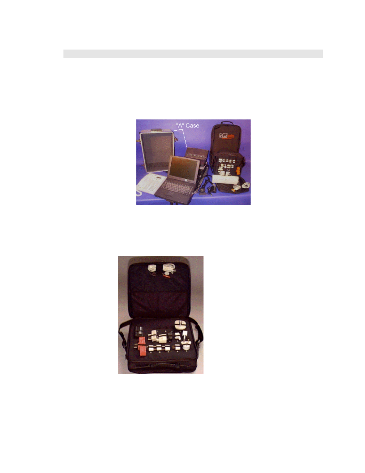
• The “A” case (
Figure 1) may contain the laptop computer, the printer, the
scanner, the camera, the power inverter, a STU-III and internally mounted
batteries and power management systems. This case contains the most
frequently used components of the GSA UNIT and will probably be the most
used.
Figure 1 "A" Case
• The “B” case (Figure 2) is a soft case that contains the various telephone and
power adapters, and a small tool kit. The A/C adapters for the various
components of the system (i.e. computer, printer, etc.) may be carried in this
case. This case should be deployed with the GSA Unit.
Figure 2 "B" Case
8
Page 9

GSA Operations
Document Number: 401-364
Case Power Sources
The GSA Unit can operate from a variety of power sources: external A/C power, external D/C
power, and from internal batteries. When connecting to or disconnecting from an external
power source, you may hear a click from inside the case. This is caused by relays within the
unit and is normal.
CAUTION: THE EQUIPMENT COVERS INSIDE THE GSA UNIT
SHOULD NOT BE OPENED! Hazardous voltages may be present at any time
and there are no field serviceable components inside.
CAUTION: Most power sources and components come with a panel or label
stating their power ranges. If these ranges are exceeded, then there is a very
strong potential to cause irreparable damage to the case and/or component
causing it to malfunction or not to work at all. Therefore do not push these
sources beyond their designated power ranges.
9
Page 10
GSA Operations
Document Number: 401-364
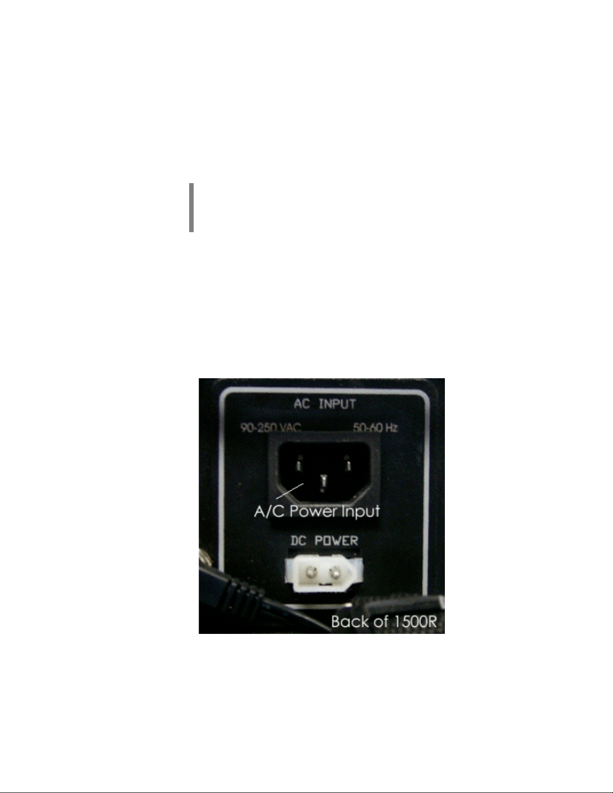
External A/C Power
The Alternating Current (A/C) connection to the GSA Unit accepts input voltages from 90 to
250 VAC at 50 to 60 Hz, as stated on the External A/C Power panel. Depending on the
components in use, the state of the various batteries in the system, and the current operating
conditions, the system will draw up to one ampere from the source. The system has circuitry
to ensure overloads do not cause damage to the GSA Unit or to the installed components. The
system also contains protection against heat by monitoring the temperature inside the case to
ensure it does not exceed 170 degrees Fahrenheit.
NOTE: When the case exceeds 170 degrees Fahrenheit, the case will shut
itself down. After the case has cooled down, the case will be able to be
turned back on. This downtime depends on how hot the case was when it
finally turned itself off.
A/C electrical power is supplied to the GSA Unit through a standard, three-wire power plug
connected at the back panel of the case (as shown in Figure 3). Connect the other end of the
power cord to a three-prong power source. Using appropriate adapters, the GSA Unit may be
connected to a wide variety of sources. Since it will accept a wide variation in input voltages
and frequency, as described above, the GSA Unit can be safely connected to standard A/C
power sources throughout most of the world. Nonetheless, precautions must be taken to
ensure the power connections are correct. In particular, the GSA Unit is not certified for
direct connection to US military aircraft since power is usually generated at 400 Hz
unless indicated on Input Power Panel.
10
Figure 3 External A/C Power Input
The GSA Unit contains circuitry that will automatically reset after an overload, but if the
system fails and does not come back up after approximately 10 minutes, the unit must be
considered in a non-recoverable condition and should be returned to the factory for repair.
Page 11
GSA Operations
Document Number: 401-364
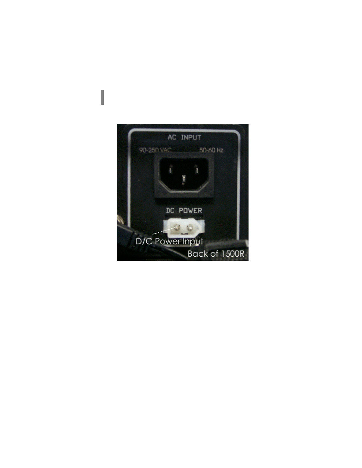
External D/C Power
The Direct Current (D/C) Power Supply connector is the small, translucent plastic, arrow
shaped connector on the back panel below the A/C power input (as shown in Figure 4). The
acceptable input voltages are 10 to 14 VDC. Nonetheless, precautions must be taken to ensure
the power connections are correct.
NOTE: If the voltages stated on the panel are exceeded, then there is the
potential to harm the components connected to the case, especially the laptop.
Figure 4 External D/C Power Input
11
Page 12
GSA Operations
Document Number: 401-364
Internal Battery System
Using internal batteries, no external power connections are required. When the GSA Unit is
connected to an external power source, the internal batteries will automatically charge with
power on or off. Fully discharged batteries may require five to ten minutes of charge prior to
laptop and peripheral operation, if the case is being used at the same time that it is charging
(connected to external power). To fully recharge the drained batteries, then they require 8 to
10 hours.
NOTE: All batteries have a limited life expectancy. Depending upon
patterns of use and charging of the case batteries, the GSA unit should be
sent back to the manufacturer every 18 to 36 months for replacement.
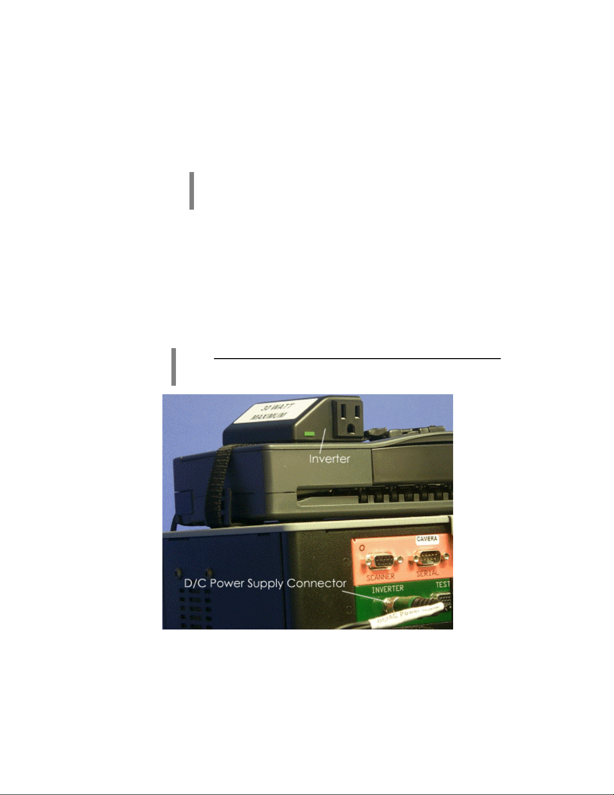
D/C-To-A/C Power Inverter
The D/C-to-A/C power inverter connects to the case through the GSA Unit power inverter
connector, which is colored green (shown in
power supply connector labeled Inverter PWR on the green panel. The range of D/C input to
the inverter is between 10 to 15 volts DC at 5 amperes. The inverter can accept any standard,
three-prong plug. The output generated by the inverter is 115 volts A/C.
Figure 5). The D/C plug connects to the D/C
NOTE: The maximum A/C wattage the inverter can safely supply is 30 Watts.
Any more than this has the potential to damage the inverter. Don’t hook your
hairdryer, shaver, or any other high wattage draw items to the inverter!
12
Figure 5 Power Inverter Panel
Page 13

GSA Operations
Document Number: 401-364
Computer Power Sources
Case Supplied Power
Since the GSA Unit is a fully integrated system, this is the preferred operating method. To
operate in this mode, dock the computer, insert the power cable on the docking bar to the
computer’s power input, and flip the CPU switch to the ON position.
Computer Battery
If you do not wish to power the computer through the case’s power supply, then you can use
the computer’s internal battery to power it. To operate in this mode, either undock the
computer or with the computer docked, flip the CPU switch to the OFF position. This
switches the computer to battery operated mode.
To recharge the computer batteries, dock the computer back into the GSA Unit with the CPU
switch in the ON position or plug the computer into a suitable A/C power source with the
supplied A/C power adapter. For the fastest recharge, the computer must be powered off.
Computer A/C Adapter
The computer normally gets its power from either the GSA Unit case or from its internal
batteries. A third way to power the computer is to plug it into an A/C power source, e.g., a
wall outlet. For this purpose, an A/C power adapter specifically designed just for the
computer has been included with the GSA Unit.
13
Page 14

GSA Operations
Document Number: 401-364
Power Management
Because the GSA Unit is a sophisticated system with multiple potential power sources and
several battery-powered components, optimal Power Management requires operator actions.
When external power, either A/C or D/C, is available, that should be the preferred operating
mode since it will generally provide the longest uninterrupted operation. One of the best
techniques when external power is not available is to take advantage of the power
management features of the laptop computer. Place the CPU switch in the off position. This
cuts off case battery power to the laptop forcing it to run on its own battery, while still
providing power to the peripheral components. When the batteries in the computer become
low with use, the CPU switch can be placed back in the on position until the computer
batteries have been restored.
After a couple of hours on case battery power, the GSA Unit internal batteries are no longer
able to fully charge the computer batteries and/or provide power to the peripherals. At this
point, the GSA Unit should be connected to external power or data should be saved to disk
and preparations made to power down the system.
The GSA Unit peripherals can consume quite a bit of power, even when just idling.
Therefore, if you anticipate operating for an extended period on the batteries, turn off any
peripherals you are not using.
14
Page 15

GSA Operations
Document Number: 401-364
Controls and Indicators
The GSA Unit control panel holds two lights and four operator accessible switches, all with
internal lights (see Figure 6).
Figure 6 Controls and Indicators
External Power Light
This light, labeled EXT PWR and located between the STORE/POWER switch and the
CPU switch, is illuminated red whenever the GSA Unit is connected to external power. The
case batteries will be recharging when this light is on.
Case Battery Status Light
This light, labeled CASE BATTERY and located between the CAMERA/COM 1 switch
and the NONSECURE/STU switch, is green when there is plenty of power remaining in the
case's internal batteries and red when the power in the batteries is low (an alarm will also
sound).
NOTE: When the alarm sounds, immediately start to shut the system down.
There is at least five minutes until the case's power is unable to support the
system. This should be enough time to save all unsaved work before the system
shuts down. However the laptop will continue to function normally, depending
upon its battery’s charge capacity.
NOTE: Switching the power switch to STORE can turn off the alarm. This also
stops all components not powered by their own power supply.
15
Page 16

GSA Operations
Document Number: 401-364
STORE / POWER Switch
In the STORE position, the computer and peripherals are disconnected from A/C and D/C
power. This should be the position of the switch when the unit is to be stored for more than
one day.
NOTE: Since the internal GSA Unit case batteries and battery charging system
are always connected to external power through the STORE or POWER
position, during long periods of storage the GSA Unit batteries can be
periodically “topped off” by applying power to the GSA Unit for a few hours.
In the POWER position, the GSA Unit peripherals (except the laptop) are powered by the
case. The computer needs both the POWER and CPU switches to be in the ON position to
operate. The normal operation should have the POWER and CPU switches on
(illuminated) with the NONSECURE/STU switch in the NONSECURE position.
CPU Switch
With the CPU power plug properly inserted and the CPU and POWER switches on, the GSA
Unit case provides power to the laptop computer and the light internal to the switch is
illuminated. With the CPU switch in the off position, the laptop computer operates on its
internal batteries.
16
Page 17
GSA Operations
Document Number: 401-364
CAMERA / COM 1 Switch
NOTE: In either position, the CAMERA/COM1 switch only works when the
NONSECURE/STU switch is in the NONSECURE position. When the
NONSECURE/STU switch is in the STU position, both COM1 and
CAMERA ports are disabled.
In the CAMERA position, the serial port of the computer is connected to the orange serial
port on the inside panel of the case.
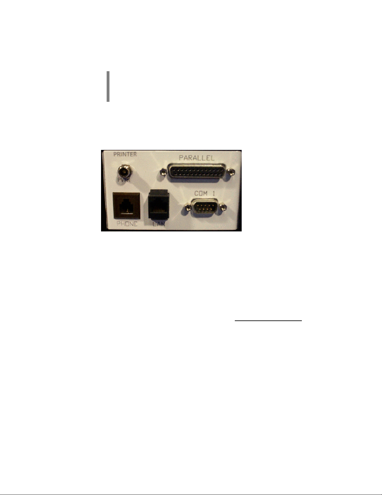
In the COM 1 position, the serial port of the computer is connected to the 9-pin COM 1
connector (DB9) on the back panel of the case (see Figure 7).
Figure 7 External COM
NONSECURE/STU Switch
When the NONSECURE/STU switch is in the STU position (the LED in the switch lights
up red), all data passes through the STU-III. In this position, the STU-III can be used in all
modes: Non-Secure Voice, Secure Voice, and Secure Data.
When the NONSECURE/STU switch is in the NONSECURE position (the LED in the
switch is not lit up), all non-secure communication connections (LAN and COM1) are
connected. Data sent or received in this mode will be only in Non-Secure mode.
17
Page 18
GSA Operations
Document Number: 401-364
Turning on the System
CAUTION: Before beginning a computer session, running a full Disk
Recovery is highly recommended to reset the entire system, especially if this is
the first session of a new series of operating sessions (see page 50).
To power up the case
• Locate the switch labeled STORE/POWER.
• Position the switch to the POWER position.
Power will now be provided to all devices in the case except the computer.
To power up the computer
• Ensure the STORE/POWER switch is in the POWER position and then turn
on the switch labeled CPU.
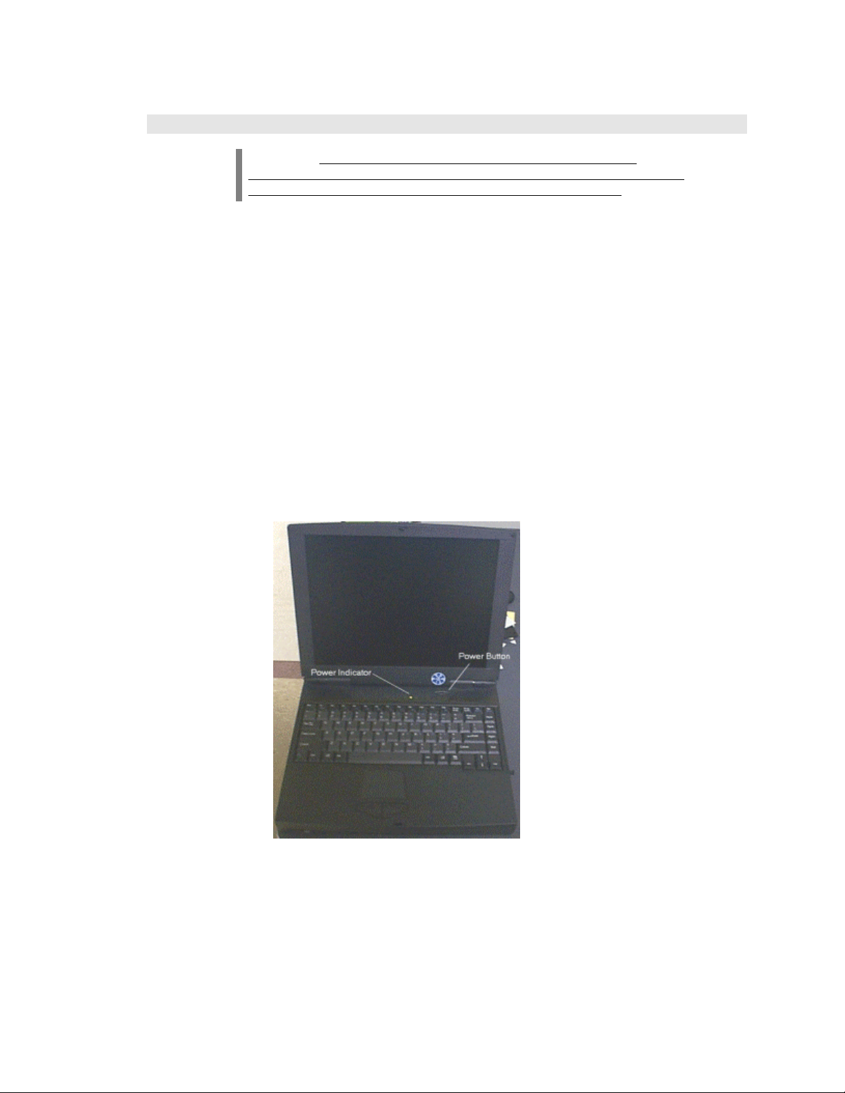
• Press the display release on the front of the computer and lift the display panel.
• Press and hold the Power Switch on the side of the laptop until the Power
Indicator light illuminates (as shown in Figure 8).
Figure 8 Power Switch and Indicator
18
Page 19

GSA Operations
Document Number: 401-364
Operating System
Logging In
When Windows98 first starts up, a login dialog will appear. If the computer is hooked up to a
network, then the first login dialog in (
appear. Either way, enter your User name and Password. Click OK. After this, Windows will
finish the boot process and you can begin work on the computer.
Figure 9) will appear. If not, then the second dialog will
Figure 9 Logging in
19
Page 20

GSA Operations
Document Number: 401-364
Shutting Down
NOTE: Before any shutdown procedure, be sure to MOVE all data files off of
the hard drive and onto removable storage media. The hard drive should be
devoid of ANY classified data. Then do a DISK RECOVERY with either the
CD for the 780 laptop or the CD and floppy for the 740. This will reset the
entire system and "erase” any data on the hard drive and reset the system.
NOTE: It is very important that you let Windows shut down your computer
before you turn the power off. Otherwise, Windows will start to exhibit
anomalous behavior.
Follow these steps to shut down the computer:
• Click Start and then Shut Down. Windows will display a box similar to that
shown in Figure 10.
20
Figure 10 Shut Down Windows
• Make sure the circle for Shut down has a dot. If it does not, click on the empty
circle and one will appear.
• Click the OK button and Windows will shut down the computer.
Page 21

GSA Operations
Document Number: 401-364
Removing PCMCIA Cards
To remove PCMCIA cards from the computer:
CAUTION: There exists a potential to damage a PCMCIA card if you do not
first stop the card before removing it.
• Left click on the PCMCIA card icon located on the lower right hand side of the computer
screen (near the clock).
• A list of cards that are currently inserted in the computer will appear.
• Select the one you want to remove and click on it.
• Wait for a confirmation notice, then remove it.
21
Page 22

GSA Operations
Document Number: 401-364
Software
Creating a Document
To create a document:
• From the Desktop, double-click on the Microsoft Office folder. This will
open a window similar to that in (Figure 11).
Figure 11 Creating a New Document.
• Double-click on one of the icons as appropriate for the document to be created.
For example, to create a new spreadsheet, double-click on the Microsoft Excel
icon. This will start the application and load an empty document ready for you
to start working.
• When you are finished editing the document, be sure to SAVE it to disk so that
it will be available for editing during a future session. This is achieved by
clicking on File -> Save.
NOTE: By default, Office 97 will save your documents in the My Documents
folder unless you specify a different location.
NOTE: Before any shutdown procedure, be sure to MOVE all data files off of
the hard drive and onto removable storage media. The hard drive should be
devoid of ANY classified data. Then do a DISK RECOVERY with either the
CD for the 780 laptop or the CD and floppy for the 740. This will reset the
entire system and "erase” any data on the hard drive and reset the system.
22
Page 23

GSA Operations
Document Number: 401-364
Retrieving an Existing Document
To retrieve an existing document:
NOTE: Unless specified otherwise, during a SAVE or SAVE AS operation of a
file, the system defaults to saving all data files in the My Documents folder.
• From the Desktop, double-click on the My Documents folder or whatever
folder you specified, to open a window similar to that in (Figure 12).
Figure 12 Retrieving an Existing Document
• Double-click on the document you want to edit. Windows will automatically
open the document using the application associated with that document.
23
Page 24

GSA Operations
Document Number: 401-364
Printing
Printer Setup
To print from the computer, first setup the printer following these instructions:
• If the computer is not connected to the docking tray, then connect it.
• Connect the printer’s power and signal cable (wrapped together in white) as shown in
Figure 13.
Figure 13 Printer connection
• Turn the printer’s power on.
• Open the printer’s cover as shown in Figure 14.
Figure 14 Printer cover
24
Page 25

GSA Operations
Document Number: 401-364
• If the cartridge is centered and empty (a beeping should be heard warning that no ink
cartridge is installed), insert an ink cartridge, close the cover, and press the cartridge
button to reset the printer.
Figure 15 Printer cartridge
• If no warning beeps are heard and the carriage is stationed on the right side of the printer,
then it should be ready to print.
• If you need to change an ink cartridge, press the cartridge button on the printer to center
the carriage. Open the lid, exchange a new ink cartridge for the old one, close the lid, and
again press the cartridge button to reset the printer.
• Once the printer finishes testing the cartridge, the printer is ready to be used.
NOTE: If printing color output, be sure the color ink cartridge is installed
If printing large quantities (more than 15) of black print output (no color),
change the ink cartridge carriage to the large black ink carriage and insert a
large black ink cartridge.
25
Page 26

GSA Operations
Document Number: 401-364
Printing a Document
To print a document:
NOTE: All of the following actions will print the document to the default
printer. If this is not what you want, then open the associated program (if not
already open) and from the menu bar click on the File menu and select Print.
This will bring up a dialog in which you can select the printer desired.
• Make sure the printer is connected (See the previous section on how to do this).
• Turn the printer’s power on.
• Now then you have the following two choices:
• For an open document, click on the printer icon.
• OR
• From the folder in which you saved the file (the default all data files is the My
Documents folder), right-click on the document and choose Print.
26
Page 27

GSA Operations
Document Number: 401-364
Imaging
Scanning an Image or a Text Document using the PageScan Scanner
To scan a picture using the page scanner:
CAUTION: The scanner is self-propelled. Do not force paper through the
scanner and do not force the scanner across a page. Damage to the scanner
may result.
CAUTION: You must lift up a crawling scanner to stop it. Please do not let it
fall off the table!
NOTE: If there is more than one scanning program open, then you will not be
able to scan. The solution to this problem is to close all scanning programs, then
proceed with the following steps.
• To attach the scanner to the base, orient the scanner so that the Logitech logo
faces you. Align the vertical plastic guide pin on the right side with the end of
the base that has a slot in which the guide pin will fit. Slide the right side with
the pin down onto the base first, then press the left side down until it snaps into
place.
• To remove the scanner from the base, lift up on the left side (Logitech emblem
facing you) of the scanner until it snaps out of place and then remove the base.
• Make sure the PageScan Scanner is connected. If it is not, then connect the
scanner cable to the connector located on the orange panel of the GSA Unit
case. There is only one cable carrying both power and data.
• Place the picture or text document to be scanned in either of the following
positions:
• With the scanner base attached, insert the document just into the feed rollers at
the front of the scanner with the paper guides and stop. Do not push paper
further.
OR
• With the scanner base detached, place the scanner section on top of the
document (Do not push or pull the scanner. It will crawl over the document on
its own).
• The scanner application program will automatically open a window similar to
that shown in Figure 16. If it does not open, double-click the Imaging folder
located on the Desktop. From there double-click PageScan Control
Center.
27
Page 28

GSA Operations
Document Number: 401-364
Figure 16 PageScan Scanner
28
Page 29

GSA Operations
Document Number: 401-364
To scan a picture:
• Click on the Picture icon as shown in Figure 16. This brings up a window
similar to that shown in Figure 17.
Figure 17 Foto Touch
• Select a Destination for the picture.
• Click on the Scan Now button to begin scanning the picture. You will get the
highest resolution scan using Black and White Picture as the Document Type.
• From here, the program will exhibit one of two behaviors. These behaviors are
as follows:
• If you selected Save to a file (select after scanning) under Destination, the
picture will be loaded into the Logitech Image Editor program. From there you
can save the picture to a file (we recommend saving the file as a JPG type file
for the greatest compatibility with other programs). You can now close Logitech
Image Editor by clicking on File and then Exit.
• If you selected a specific graphics program, the scanned picture will load up into
that program.
29
Page 30

GSA Operations
Document Number: 401-364
To scan (OCR) a text document:
• Click on the ABC icon as shown in Figure 16. This brings up a window similar
to that in Figure 18.
30
Figure 18 OCR Scan
• Select the Destination of the document.
• Click on the Scan Now button to begin scanning the text.
• From here, the program will exhibit one of two behaviors. These behaviors are
as follows:
• If you selected Save to a file (select after scanning) under Destination, a Save
As window will come up for you to save the file under the desired destination
(we recommend saving the document as a Word for Windows *.rtf file for the
greatest compatibility with other programs). Type in the .rtf file extension in the
file name box or the file will be lost.
• If you selected a specific application program, the scanned document will load
up into that program.
Page 31

GSA Operations
Document Number: 401-364
Non-Secure Communication Connections
Connecting to a Phone Line for Non-Secure Connections
To connect the computer to a phone line:
• Flip the NONSECURE/STU switch to the NONSECURE position.
• Connect an RJ11 phone cable (a regular phone line) from the phone connection in the
back of the case (shown in
Figure 19) to the phone connection desired.
Figure 19 Telephone Connection
• Take the "Y" Phone Cable and connect the single plug end to the docking bar and insert
the RJ11 plug into the RJ11 connector and the RJ45 plug into the RJ45 connector of the
Xircom card (see Figure 20).
• Insert the Xircom Card into the PCMCIA card slot of the computer (see Figure 20).
Figure 20 LAN/Modem Connections
31
Page 32

GSA Operations
Document Number: 401-364
• The modem is ready for use.
Connecting to a Local Area Network (LAN) to Access the Internet
To connect the computer to a LAN:
• Flip the NONSECURE/STU switch to the NONSECURE position.
• Connect an RJ45 LAN cable (looks like the RJ11 phone line except a little thicker) from
the LAN connection in the back of the case (shown in
desired.
• Take the "Y" Phone Cable and connect the single plug end to the docking bar and insert
the RJ45 plug into the RJ45 connection of the Xircom card (see Figure 20).
• Insert the Xircom Card into the PCMCIA card slot of the computer.
• Click on the Start button and go to the Run option. Type in the word winipcfg.
• Click on Renew All and OK to get access to the LAN.
NOTE: If the network connection is denied, then restart the computer with the
LAN connection still in place. When Windows98 starts up, it will ask you for the
network password. Once supplied, then the computer will be on the network.
Figure 19) to the LAN connection
• See the sections on non-secure communications for more details on how to use the
modem.
32
Page 33

GSA Operations
Document Number: 401-364
Connecting to the Internet over a Phone Line
To connect the computer to the Internet over a phone line:
• Connect the computer to a phone line as detailed in the subsection titled Connecting to a
Phone Line on page 31.
• Double-click the Comms folder located on the Desktop.
• Double-click Dial-Up Networking.
NOTE: The first time you do this a dialog box stating Welcome to Dial-Up
Networking might appear. Any other time you access Dial-Up Networking, you
will bypass this dialog box, in which case you would click Make New
Connection to make a new connection. Click Next(see Figure 21).
Figure 21 Welcome Message
• In the first box, type a name for the connection type, i.e. GSA.
• In the drop-down box, select the modem you want to use for the connection.
• Click Next (see
Figure 22).
33
Page 34

GSA Operations
Document Number: 401-364
Figure 22 New Connection Setup
• Enter in a phone number to the machine you are trying to connect to.
NOTE: If using an INMARSAT as your transmission source, you must insert
01# (13 commas) (country code, e.g. USA is 001) (phone number to be dialed) #.
For example if you wanted to call someone in the USA, then you would dial
01#,,,,,,,,,,,,,0015555555555# . This allows the satellite connection to be made.
34
Page 35

GSA Operations
Document Number: 401-364
Figure 23 Phone Number
• Click Next (see Figure 23).
• Click Finish.
• Using the right mouse button, click on the connection made. While holding down the
mouse button, drag the icon onto the desktop. Let go of the button.
• Click on Create Shortcut.
• This will put a shortcut on the Desktop to the connection.
• Double-click on the shortcut. A Connect To window will appear with the information
provided.
• Click Connect. This will start the call and make the connection.
35
Page 36

GSA Operations
Document Number: 401-364
Non-Secure Data: Sending and Receiving
CAUTION: When in this mode, only Non-Secure data can be transmitted.
Sending Non-Secure Data
To transfer non-secure data using ProComm and the PCMCIA Modem:
• Insert the Xircom PCMCIA card as outlined in the Non-Secure Communication
Connections section on Page 31.
• Flip the NONSECURE/STU switch to the NONSECURE position.
• Ensure that the receiving party has ProComm Plus Data Terminal open and ready to
receive the data.
• Click on the Comms folder on the Desktop.
• Double click on ProComm Data Terminal.
• Make sure that the third box in the ProComm Data Terminal status line reads
Modem of Xircom 10-100+56. If it does not, click on it and select Modem of
Xircom 10-100+56 from the list.
• Click on CmdMode (located at the bottom right of the ProComm screen). A
message will appear stating “This modem is no longer accessible to other
applications.” Type ATDT and the phone number with no spaces (i.e.
ATDT5555555). Press <ENTER>.
36
Page 37

GSA Operations
Document Number: 401-364
• There are three indicators in ProComm Plus that let you know you are
connected. They are the phone icon on the toolbar will be off the hook, the cd
and cts lights will be red, and the word Connected will appear at the lower right.
See Figure 24.
Figure 24 ProComm Plus Indicators
37
Page 38

GSA Operations
Document Number: 401-364
• Once the connection is established, click on the send folder (this is the folder
with the arrow pointing up and out of the folder). This will open the Send File
window as shown in
Figure 25.
Figure 25 ProComm Send File
• To start the transmission, click on the file to be transferred and click OK.
• When the transmission is complete, exit ProComm by clicking on File and then
Exit.
Receiving Non-Secure Data
To receive non-secure data using ProComm and the Xircom card:
• Insert the Xircom PCMCIA card as outlined in the Non-Secure Communication
Connections section on page 31.
• Flip the NONSECURE/STU switch to the NONSECURE position.
• Click on the Comms folder on the Desktop.
• Double click on ProComm Data Terminal.
• Make sure that the third box in the ProComm Data Terminal status line reads
Modem of Xircom 10-100+56. If it does not, click on it and select Modem of
Xircom 10-100+56 from the list.
38
Page 39

GSA Operations
Document Number: 401-364
• There are two ways to answer a data call:
• To automatically answer incoming calls, set the Xircom to answer data calls
under the Options->System Options->Modem Connection.
• To manually answer incoming calls, click on CmdMode (located at the
bottom left of the ProComm screen). A message will appear stating “This
modem is no longer accessible to other applications.” Type ATA when you
see RING on the screen.
• Once the connection is established, GSA Unit will automatically receive the data
and open the Receive window (see Figure 26). All files received are then put in
the C:\My Documents\Data Download folder which can be reached by
double-clicking on the My Documents folder located on the Desktop.
Figure 26 ProComm Receive Screen
39
Page 40

GSA Operations
Document Number: 401-364
Non-Secure Faxes: Sending and Receiving
CAUTION: When in this mode, only Non-Secure data can be transmitted.
Sending a Non-Secure FAX
To send a non-secure FAX:
• Insert the Xircom PCMCIA card as outlined in the Non-Secure Communication
Connections section on page 31.
• Flip the NONSECURE/STU switch to the NONSECURE position.
• Ensure that the receiving party has ProComm Plus Fax Status open and ready to receive
the fax, if faxing to another GSA unit.
• From the My Documents folder, double-click on the file you want to send. If the
document is already open, go to the next step.
• On the File menu, select Print. This will bring up the following screen (see Figure 27).
40
Figure 27 Selecting the ProComm Plus Printer
• Select ProComm Plus 32 Fax.
• Click OK.
• This will bring up the ProComm Plus – Send Fax on-screen form as shown in
Figure 28.
Page 41

GSA Operations
Document Number: 401-364
Figure 28 ProComm Plus – Send Fax
• Fill in the Send to box and the FAX number box, then click Send. This will
bring up a screen similar to that shown in
Figure 29.
41
Page 42

GSA Operations
Document Number: 401-364
Figure 29 ProComm Plus Fax Status
• Click on Xircom card in the list shown in Figure 29 to view the sending status of the fax.
42
Page 43

GSA Operations
Document Number: 401-364
Receiving a Non-Secure FAX
To receive a non-secure FAX document:
• Insert the Xircom PCMCIA card as outlined in the Non-Secure Communication
Connections section on page 31.
• Flip the NONSECURE/STU switch to the NONSECURE position.
• Double-click the Comms folder located on the Desktop.
• Double-click the ProComm Fax Status icon to open a window similar to that
shown in
• When the remote end of the link starts sending the FAX, ProComm Plus will
automatically save it to your disk in the default location of C:\My
Documents\Fax Inbox. This folder can be reached by clicking on the My
Documents folder located on the Desktop.
Figure 29. The system is ready to automatically receive a FAX.
43
Page 44

GSA Operations
Document Number: 401-364
Troubleshooting
Case and Power System
Nothing works
• If running from an external power source, is the red External Power light on the
GSA Unit control panel lit? If not, the GSA Unit is not actually connected to
external power. Possible causes of this problem:
• The A/C power cord is plugged into a power strip or plug that is not turned
on.
• The D/C power cord is connected to a source, e.g., a cigarette lighter, which
requires the key in the vehicle to be turned on.
• The power cord is not fully inserted into the socket or the power source has
a blown fuse or circuit breaker.
• If the GSA Unit is running from internal battery power and the control panel
switch lights do not come on or are only dimly lit, the case batteries are probably
discharged.
44
Page 45

GSA Operations
Document Number: 401-364
Computer
I can’t find my files
• Ensure the folder is the one in which the files were originally stored.
• If it was a recent file, then click on the Start button and go to Documents. A list
of the most current files modified is there.
• Click on the Recycle Bin located on the Desktop.
• Click on the Start button. From there go to Files and select Files or Folders.
Type in the file you are looking for and click the Find Now button.
I can’t find my programs
• Check the Properties for the program to ensure the link or shortcut to the
program has not changed.
• Click on the Start button. From there go to Files and select Files or Folders.
Type in the file you are looking for and click the Find Now button.
• Click on the Start button. From there go to Programs. There should be a listing
of all the major programs located on the list. Find the program from that list.
• Backup all work to an external media (i.e. floppy disk or PCMCIA hard card)
and follow the procedures outlined in Disk Recovery Procedures on page 50.
45
Page 46

GSA Operations
Document Number: 401-364
Printer
Nothing prints
• Ensure the printer is turned on and that the paper is properly inserted.
• Check the cable from the GSA Unit to the printer.
One or more colors are missing
• Check or replace the ink cartridge.
The printer seems to be printing, but nothing shows up on the paper
• Check or replace the ink cartridge.
46
Page 47

GSA Operations
Document Number: 401-364
Scanner
Nothing scans
• Ensure the scanner connector is properly inserted into the GSA Unit – especially
check that the connector is straight when it is inserted into the GSA Unit case.
• Close all scanning programs. Afterwards start the scanning program you want to
use.
The paper jams
• Remove creases before inserting the paper.
• Ensure the bottom to the scanner is properly attached.
Scanned Images or Text comes out weird
• Insert the Logitech calibration sheet (looks like a grayscale sheet) into the feed rollers.
This will bring up the Logitech PageScan Control Center. From the menu bar, select
Scanner -> Recalibrate Scanner. The scanner should scan the card and recalibrate the
scanner.
I need to scan a large document (larger than 8.5 inches wide)
• Remove the bottom of the scanner and ensure the cable to the scanner is
completely extended from the GSA Unit. Put the scanner at one end of the
document to be scanned and start the scanning software. As the scanner pulls
itself across the document, monitor the cable to ensure it does not become
entangled. You must lift up the crawling scanner to stop it. Please do not let it
fall off the table!
47
Page 48

GSA Operations
Document Number: 401-364
Modem/FAX Cards
General
• Make sure that the modem is properly inserted into the PCMCIA card slot. If it
is properly inserted then a card icon should appear in the system tray (the area
next to the clock).
• Try reinserting the communications card.
• Make sure that only one communications card is in the PCMCIA slots.
I cannot connect to the network
• Go to the Start Menu and select Run. Type in winipcfg. Click Renew All.
Click OK.
• Restart the computer.
I cannot send a fax
• Shut down all communications programs. Disable the card on the taskbar. Remove the
card. Insert the card. Restart the communications program desired. Try sending the fax
again.
• If it is a Non-Secure fax, make sure that the NONSECURE/STU switch is in the
NONSECURE position.
• If it is a Secure fax, make sure that the NONSECURE/STU switch is in the STU
position and that you have made a secure connection with a STU-III.
• From the Fax program, clean out the inbox, sent fax box, and the outbox. Try sending the
fax again.
I cannot receive a fax
• If it is a non-secure fax, make sure that ProComm Plus is set to answer Fax only, not Data
and Fax. To change the settings in ProComm Plus:
• Open ProComm Plus Fax Status.
• Go to Options->System Options->Modem Connection.
• Select Modem of Xircom 10-100+56 under Current Modem Connection.
• Uncheck the box (box should be empty) next to Accept data terminal calls.
• Click OK.
48
Now ProComm Plus Fax Status should read Faxes under Auto-Answer.
Page 49

GSA Operations
Document Number: 401-364
PCMCIA Cards
Computer does not recognize the card
• Remove the card from the PCMCIA slot. Firmly reinsert the card. An
acknowledgement beep should sound and a PCMCIA card icon in the system
tray at the lower right of the screen should appear.
• Every time you remove the card, make sure you stop it first. To do this, left click
on the card icon in the tray to bring up the list of cards currently active. Select
the card you want to stop and click Stop.
49
Page 50

GSA Operations
Document Number: 401-364
Disk Recovery Procedures
The following procedures may be used to restore the GSA Unit software to its original
configuration. The entire process will take about 10 minutes to complete.
CAUTION: These procedures will destroy all existing data on
your hard disk!
• There are three ways to perform the recovery of a GSA Unit system.
• If the computer’s power is on, open the CD-ROM drive and insert the ASD
System Image Recovery CD-ROM. Close the CD-ROM drive. Click on the
Start button and select Shut Down. When a shut down window appears,
choose Restart.
• If the computer’s power is off, paper clip the CD-ROM drive open through
the pinhole and insert the ASD System Image Recovery CD-ROM. Close
the CD-ROM drive and turn on the computer’s power.
• If the computer’s power is off, turn on the computer’s power. When the
computer’s bios posts (text first appears on the screen) open the CD-ROM
drive and insert the ASD System Image Recovery CD-ROM.
• Turn the system power on.
• If you do not want to continue press N. Press Y to continue the process and
replace all the data on the hard drive.
• The system will reboot when recovery is complete.
• If the system tries to perform the recovery again, simply remove the ASD
System Image Recovery CD-ROM and reboot the computer or press N and
reboot the computer.
50
Page 51

GSA Operations
Document Number: 401-364
Appendix A: Panel Color Coding
Color Purpose Cables Location Type Input(s)/Output(s)
Orange Camera /
Scanner
3Front
DB9 Female Scanner Signal / Power
Connector
DB9 Male Camera Data/Serial
2.1mm Camera Power
2.5 mm Inverter PowerGreen Inverter 1 Front
Red STU-III 3 Back
Black Power 3 Back
White COM/
Printer
5 Back
DB15 Female
DB25 Male STU Data Interface
RJ11 Communications
5-Pin Receptacle STU Power
3 Prong AC Input AC Power
DC Input DC Power
Case Battery
Connector
DB25 Female Printer Signal
RJ11 Phone
RJ45 LAN
DB9 Male COM1
2.5 mm Printer Power
DO NOT USE
Case Battery
51
Page 52

GSA Operations
Document Number: 401-364
Appendix B: Secure Switch Matrix
Switch/Connections Connected Not Connected
STU STU COM (Phone)
STU PWR
STU Data
Non Secure LAN (Docking Bar)
Phone (Docking Bar)
COM1 (White)
CAMERA (Orange)
LAN (Docking Bar)
Phone (Docking Bar)
COM1 (White)
CAMERA (Orange)
STU COM (Phone)
STU PWR
STU Data
52
Page 53

GSA Operations
Document Number: 401-364
Appendix E: Components
Hardware Manufacturer
1500 Integrator Case A w/STU-III
mounting
Accessory Case B Action Systems
Shipping Case Action Systems
Tecra 780CDM Toshiba
Toshiba External Floppy Drive Toshiba
8.1 GB Hard Drive (Installed) Toshiba
Li-Ion Battery (Installed) Toshiba
5.0 GB Hard Drive (Spare) Toshiba
Li-Ion Battery (Spare) Toshiba
LS10 Coolscan Film Scanner Nikon
Color Printer BJC80 Canon
Zip Internal SCSI 100MB Iomega
PageScan Color Scanner Logitech
Action Systems
PCMCIA Cards Manufacturer
Mobile Video Pro, Nogatech Nogatech
Slim SCSI Card Adaptec
CreditCard Ethernet 10/100 + 56K
Xircom
Modem
56k Modem/LAN, Xircom
1040MB Hard Drive Card, Calluna Calluna
Xircom
Cables Manufacturer
A/C Power Cable
D/C Power Cable
Printer Power Cable, 1 foot Action Systems
Printer Power Extension, 6 feet Action Systems
Printer Signal Cable, 1 foot Action Systems
Action
Action
Systems
Systems
53
Page 54

GSA Operations
Document Number: 401-364
Printer Signal Cable, 6 feet
Phone Cable, 10 feet Action Systems
Action Systems
LAN Cable, 10 feet
LAN/Modem Y cable
Video Capture Cable, composite Nogatech
Video Capture Cable, s-video (2 parts) Nogatech
STU-III Phone Cable Action Systems
STU-III Power Cable Action Systems
STU-III Data Cable Action Systems
SCSI cable Adaptec
SCSI cable extension Action Systems
CoolScan Power Cable, 25 inches Action Systems
Zip Drive Power Cable, 25 inches Action Systems
Action
Action
Systems
Systems
A/C Adapters Manufacturer
Notebook AC Power Adapter Toshiba
Canon AC Power Adapter Canon
Accessories Manufacturer
Scanner Base Logitech
Nogatech Video Camera w/ headphone
set
Canon Printer Expendables Kit Canon
International Power Adapters Action Systems
International Phone Adapters Action Systems
1-to-3 AC Power Adapter Action Systems
Screwdriver Set Action Systems
SCSI Terminator (1 of 2) Krista
SCSI Terminator (2 of 2) Krista
Nogatech
Software Manufacturer
Windows 98 Microsoft
54
Page 55

GSA Operations
Document Number: 401-364
Plus! 98 Microsoft
Office 97 Pro
Photoshop v5.0 Adobe
Acrobat Reader 4.0 Adobe
Navigator 4.51 (Free Download) Netscape
QuickSolve 2.0 Kodak
Pkzip v2.50
Procomm Plus v4.7
VirusScan v4.0, McAfee
HiJaak Pro v4.5
WinZip v7.0
Norton 2000 (Loaded) Action Systems
GSA Recovery CD
Microsoft
Pkware
Quarterdeck
Network Associates
IMSI
Mak
Niko
Systems
Action
Manuals Manufacturer
GSA Operations Manual Action Systems
Windows 98
Photoshop v5.0 Adobe
Pkzip v2.5
Procomm v4.7 Quarterdeck
McAfee VirusScan v4.0
HiJaak Pro IMSI
BJC80 Printer Canon
Toshiba Laptop Toshiba
Logitech Scanner Logitech
Adaptec 1460 Adaptec
Nogatech Video Conference Card Nogatech
Calluna Calluna
Microsoft
Pkware
Network Associates
55
Page 56

GSA Operations
Document Number: 401-364
Warranty Information
Warranty of Supplies of a Noncomplex Nature
ONE-YEAR LIMITED WARRANTY
Action Systems, a Division of V&A Incorporated (hereafter referred to as Action Systems)
warrants that the hardware (but not the software) included in the product sold by Action
Systems will be free from defects in materials and workmanship for one (1) year from the
date of shipment by Action Systems.
NINETY-DAY REPLACEMENT PARTS LIMITED WARRANTY
Replacement parts shipped by Action Systems are warranted against defects in materials and
workmanship for ninety (90) days from the date of shipment by Action Systems or until the
expiration date of the original One, Two or Three-Year Limited Warranty, Two-Year Limited
Warranty or One-Year Limited Warranty, as the case may be, whichever is longer.
TERMS OF LIMITED WARRANTIES
The One, Two or Three-Year Limited Warranty and the Ninety-Day Replacement Parts
Limited Warranty are granted to the initial customer end-user only and are nontransferable.
Any claims under these warranties must be made before the end of the applicable warranty
period. During such period Action Systems, at its option, will: repair or replace any part
covered by the One, Two or Three-Year Limited Warranty or the Ninety-Day Replacement
Parts Limited Warranty which is determined by Action Systems to be defective in materials or
workmanship, or provide a credit or refund.
Action Systems reserves the right to substitute functionally equivalent new or serviceable
used parts. Action Systems’ responsibility is limited to repair, replacement, credit or refund,
any of which may be selected by Action Systems at its sole discretion. Unless otherwise
stated herein, the cost of labor is not covered by any Action Systems warranty.
The One, Two or Three-Year Limited Warranty and Ninety-Day Replacement Parts Limited
Warranty cover only defects arising under normal use and do not include malfunctions or
failures resulting from: misuse, abuse, neglect, alteration, problems with electrical power,
usage not in accordance with product instructions, acts of nature, unusual temperatures or
humidity, improper installation or damage to the LCD display screens determined by Action
Systems to have been caused by the customer, with respect to notebook computers, or repairs
made by anyone other than Action Systems, Action Systems-qualified third-party service
providers, or you with the assistance of Action Systems technical support.
The One, Two or Three-Year Limited Warranty and Ninety-Day Replacement Parts Limited
Warranty does not cover defects or damage arising from the disassembly, or attempted
disassembly, without the assistance of Action Systems technical support or other authorized
personnel, of the product.
56
Page 57

GSA Operations
Document Number: 401-364
RETURN PROCEDURES
You are responsible for returning products to Action Systems at your expense. Prior to
returning product(s) to Action Systems for warranty service, you must obtain a Return
Merchandise Authorization (RMA) number from Action Systems by calling 505 526-6606
(domestic and international customers). For the purpose of these limited warranties and
support policies, a “domestic” customer is a customer located in the contiguous 48 States of
the United States of America, Hawaii, Alaska, and Canada. To obtain an RMA number, you
must provide Action Systems with your valid charge card number (VISA, MasterCard or
other issuer acceptable to Action Systems) or an Action Systems-authorized open Purchase
Order to cover the replacement cost of the part or product at the time you obtain the RMA
number. If you fail to return the defective part or product to Action Systems as set forth
below, Action Systems will charge you both the cost of the part or product and a twenty five
percent (25%) restocking fee. Action Systems will process this charge only if you fail to
return the defective part or product at your expense within ten (10) business days (thirty (30)
business days for international customers) from the date you obtain the RMA number.
Replacement parts or products will be shipped to domestic customers at Action Systems’
expense, subject to availability, via second day delivery service and at international
customers’ expense within five (5) business days from the date they obtain an RMA number.
Action Systems shall not be responsible for failure of the delivery service to make on-time
delivery. All costs of returning the defective part or product to Action Systems, including
insurance, must be paid by you. All costs relating to the shipment of defective parts or
products, including insurance, and if applicable, import and export duties, and all other fees
and charges imposed by government or quasi-governmental agencies or officials must be paid
by international customers for shipment both ways. If you cannot provide your valid charge
card number or Action Systems-authorized open Purchase Order, Action Systems will not
ship replacement products.
You must ship the product(s) to Action Systems in the original packaging, prepaid and
insured by you, (International customers must ship the product(s) to Action Systems via DHL,
Federal Express, UPS or another international courier acceptable to Action Systems (a
“Qualified Courier”) with the RMA number clearly identified on the packaging.
Please retain your shipping information, including tracking numbers, until your account has
been credited by Action Systems. This will serve as your proof of return. Any product(s)
replaced by Action Systems shall become the property of Action Systems. If Action Systems
determines that failure of the product(s) was not a result of a defect in materials or
workmanship, Action Systems reserves the right to charge you for parts and labor at Action
Systems’ then current labor rate. Action Systems will advise you prior to assessing these
charges.
TECHNICAL SUPPORT POLICY
Action Systems provides free telephone technical support service with respect to installation
and configuration of all hardware products sold by Action Systems. Action Systems also
provides free telephone technical support service with respect to the configuration of factory
installed software for thirty (30) days from the date of shipment. The Action Systems
telephone technical support service number is 505 526-6606 (domestic and international
customers).
57
Page 58

GSA Operations
Document Number: 401-364
TECHNICAL SUPPORT PROCEDURE AND SERVICE (FOR DOMESTIC CUSTOMERS ONLY)
If you need technical support for your Integrator, and are a domestic customer, please call 505
526-6606 to speak with an Integrator technician. The technician will troubleshoot the reported
problem and determine if the product should be returned for further diagnosis. If the
technician believes a computer problem cannot be resolved by telephonic technical support,
and you have owned the computer for no more than one year from the date originally shipped
to you, you will be entitled to the Action Systems One Year Standard Service. The cost of
labor is covered by Action Systems under this service. The procedures for this service are as
follows:
One Year Standard Service
1. Before you ship your computer for Service, you must call 505 526-6606. The
technician will contact an overnight carrier and the carrier will send packaging
materials and instructions to you.
2. When you receive the packaging materials, read the instructions and call the carrier
at the number provided in the instructions to request pick-up. You must completely
package the product prior to the carrier’s pick-up.
3. The carrier will pick up the packaged product from the agreed upon location and
deliver it to the repair location.
4. Once the repair is complete, the carrier will return the product to the previously
agreed upon location.
NOTE:
Action Systems is committed to a timely product repair process. Therefore, every reasonable
effort will be made to return repaired products to you within seven (7) business days from the
time of the carrier’s pick-up under the One Year Standard Service. Action Systems is not
responsible for delays in the repair process.
Optional Second and Third Year Service
You may purchase a second and third year extended service at the time of your computer
purchase. The cost of labor is covered under this service. You may also purchase expedited
product repair as part of your extended service, which shall cover years, one, two and three.
Under this process, every reasonable effort will be made to return repaired products to you
within three (3) business days from the time of the carrier’s pick-up. Call 505 526-6606 for
details. Action Systems is not responsible for delays in the repair process.
58
This service option includes a preventive maintenance check where each unit is subjected to
an acceptance test after which all components, which have degraded due to norm wear and
tear, will be replaced. Case batteries, cable and case connectors are those components, which
typically will be repaired or replaced.
Page 59

GSA Operations
Document Number: 401-364
Components missing or subjected to failures resulting from: misuse, abuse, neglect, alteration,
problems with electrical power, usage not in accordance with product instructions, acts of
nature, unusual temperatures or humidity, improper installation or damage to the LCD display
screens determined by Action Systems to have been caused by the customer, with respect to
notebook computers, or repairs made by anyone other than Action Systems, Action Systemsqualified third-party service providers, or you with the assistance of Action Systems technical
support are not covered by this warranty provision.
All product(s) returned to you will include verification of applicable repair, if any. If you have
any questions concerning the technical support procedure or product repair, please call 505
526-6606.
NOTE:
The above service options are only available for customers located in the contiguous 48 States
of the United States of America, Alaska, Hawaii and Canada. International customers must
call 505 526-6606 for instructions regarding service.
LIMITATIONS
PRODUCTS SOLD BY ACTION SYSTEMS ARE NOT AUTHORIZED FOR USE AS
CRITICAL COMPONENTS IN LIFE SUPPORT DEVICES OR SYSTEMS WITHOUT
THE EXPRESS WRITTEN APPROVAL OF THE CEO OF ACTION SYSTEMS. ACTION
SYSTEMS MAKES NO WARRANTY WHATSOEVER WITH RESPECT TO SOFTWARE
INCLUDED IN ANY PRODUCTS SOLD BY ACTION SYSTEMS, AND ALL
SOFTWARE IS SOLD “AS IS” AND “WITH ALL FAULTS.”
EXCEPT AS SET FORTH HEREIN, ACTION SYSTEMS MAKES NO WARRANTIES,
EXPRESSED OR IMPLIED, AND DISCLAIMS AND NEGATES ALL OTHER
WARRANTIES, INCLUDING WITHOUT LIMITATION, IMPLIED WARRANTIES OF
MERCHANTABILITY, FITNESS FOR A PARTICULAR PURPOSE AND CONFORMITY
TO MODELS OR SAMPLES. SOME JURISDICTIONS DO NOT ALLOW LIMITATIONS
ON IMPLIED WARRANTIES, SO THESE LIMITATIONS MAY NOT APPLY TO YOU.
THE WARRANTIES SET FORTH HEREIN GIVE YOU SPECIFIC LEGAL RIGHTS,
AND YOU MAY HAVE OTHER RIGHTS WHICH VARY FROM JURISDICTION TO
JURISDICTION. IN NO EVENT SHALL ACTION SYSTEMS BE LIABLE FOR ANY
INDIRECT, SPECIAL, INCIDENTAL OR CONSEQUENTIAL DAMAGES. SOME
JURISDICTIONS DO NOT ALLOW THE EXCLUSION OR LIMITATION OF
INCIDENTAL OR CONSEQUENTIAL DAMAGES, SO THE ABOVE EXCLUSION OR
LIMITATION MAY NOT APPLY TO YOU. NO VARIATION OR EXCEPTIONS IN THE
TERMS STATED HEREIN CAN BE MADE WITHOUT WRITTEN AUTHORIZATION
BY THE PRESIDENT OF ACTION SYSTEMS. A “FULL REFUND” AS USED ABOVE
SHALL INCLUDE THE PURCHASE PRICE PAID BY THE CUSTOMER, BUT SHALL
59
Page 60

GSA Operations
Document Number: 401-364
NOT INCLUDE SHIPPING COSTS, INSURANCE, AND, IF APPLICABLE, IMPORT
AND EXPORT DUTIES, AND ANY OTHER FEES AND CHARGES IMPOSED BY
GOVERNMENT OR QUASI-GOVERNMENTAL AGENCIES, ALL OF WHICH MUST
BE PAID BY YOU.
GOVERNING LAW, JURISDICTION AND COSTS
THESE LIMITED WARRANTIES ARE INCORPORATED INTO AND ARE ESSENTIAL
AND MATERIAL PROVISIONS OF THE TERMS AND CONDITIONS OF SALE OF
ACTION SYSTEMS PRODUCTS TO YOU (SALE TERMS). ALL DISPUTES ARISING
OUT OF OR RELATED TO THE LIMITED WARRANTIES SET FORTH HEREIN
(CUSTOMER DISPUTES) SHALL BE GOVERNED BY THE LAWS OF THE STATE OF
NEW MEXICO. THE CUSTOMER HEREBY CONSENTS TO THE JURISDICTION AND
VENUE OF THE STATE COURTS OF NEW MEXICO TO RESOLVE ANY AND ALL
CUSTOMER DISPUTES WITH ACTION SYSTEMS, AND THE CUSTOMER WAIVES
ALL DEFENSES TO SUCH JURISDICTION AND VENUE INCLUDING, BUT NOT
LIMITED TO, ANY DEFENSE BASED ON INCONVENIENT FORUM. IN THE EVENT
THE CUSTOMER AND ACTION SYSTEMS ARE UNABLE TO RESOLVE ANY
CUSTOMER DISPUTE, AND ANY COLLECTION ACTION, SUIT OR OTHER
JUDICIAL PROCEEDING IS COMMENCED, THE PREVAILING PARTY IN ANY
SUCH COLLECTION ACTION, SUIT OR JUDICIAL PROCEEDING SHALL BE
ENTITLED TO RECOVER ITS COSTS AND REASONABLE ATTORNEYS’ FEES
INCURRED.
60
 Loading...