

Xip NVR04 LION User Manual

Network Video Recorder
XIP – NVR04 LION
User’s Manual
Version 1.3
NVR User’s Manual
1
Caution and Preventive Tips
Handle with care, do not drop the unit
Mount the unit in an equipment rack or place it on a solid, stable surface.
Indoor use only. Do not place the unit in a humid, dusty, oily, or smoky site.
Do not place it in an area with poor ventilation or in an area close to fire or other sources of
heat. Doing so may damage the unit as well as cause fire or an electric shock.
When cleaning is necessary, shut down the system and unplug the unit from the outlet
before uncovering the top cover. Do not use liquid cleaners or aerosol cleaners. Use only a
damp cloth for cleaning.
Always shut down the system prior connecting or disconnecting accessories, with the
exception of USB devices.
This symbol intends to alert the user to the presence of important operating and
maintenance (servicing) instructions in the literature accompanying the
appliance.
This symbol intends to alert the user to the presence of unprotected “Dangerous
Voltage” within the product’s enclosure that may be strong enough to cause a
risk of electric shock.

NVR User’s Manual
2
Important Information
Before proceeding, please read and observe all instructions and warnings in this manual.
Retain this manual with the original bill of sale for future reference and, if necessary, warranty
service. When unpacking your unit, check for missing or damaged items. If any item is missing,
or if damage is evident, DO NOT INSTALL OR OPERATE THIS PRODUCT. Contact your
dealer for assistance.
WARNING
RISK OF EXPLOSION IF THE RTC BATTERY ON THE MAINBOARD IS REPLACED
WITH AN INCORRECT TYPE. DISPOSE THE USED BATTERIES ACCORDING TO THE
INSTRUCTIONS.

NVR User’s Manual
3
Table of Contents
1. Overview ....................................................................................................................... 6
2. System Setup ................................................................................................................ 7
2.1 Position the Unit ..................................................................................................... 7
2.2 Connect Devices to the Unit ................................................................................... 7
2.3 Front Panel LEDs ................................................................................................... 8
2.4 Rear Panel Connectors .......................................................................................... 8
3. General System Setup ............................................................................................... 10
3.1 USB Mouse Operation.......................................................................................... 11
3.1.2 Functional Keys ......................................................................................... 11
3.2 Enter OSD Setup Menu ........................................................................................ 13
3.2.1 User Management ..................................................................................... 13
3.3 Reboot and Shutdown .......................................................................................... 15
3.3.1 HDD Auto Scan .......................................................................................... 16
3.4 System Date/time Setting ..................................................................................... 17
3.4.1 Set Date/time ............................................................................................. 17
3.4.2 Daylight Saving Time ................................................................................. 18
3.4.3 Network Time Protocol Setup ................................ ................................ .... 18
3.5 IP Camera Setting ................................................................................................ 19
3.5.1 IP Camera Information ............................................................................... 20
3.5.2 Connection Setup ...................................................................................... 22
3.5.3 Device Setup ............................................................................................. 24
3.5.4 Activated .................................................................................................... 24
3.5.5 Status ......................................................................................................... 24
3.5.6 Copy Settings ............................................................................................ 25
3.6 Record Schedule/Quality Setting .......................................................................... 26
3.6.1 Schedule Setup ......................................................................................... 26
3.6.2 Preset Record Configuration ..................................................................... 27
3.6.3 Advance Schedule Setup .......................................................................... 27
3.6.4 Data Lifetime Setup ................................................................................... 29
3.6.5 Circular Recording ..................................................................................... 30
3.6.6 Audio Recording ........................................................................................ 30
3.6.7 Purge Data ................................................................................................. 30
3.6.8 Pre-Alarm Recording ................................................................................. 31
4. NVR Operation ............................................................................................................ 32
4.1 View Live/Playback Videos ................................................................................... 32
4.1.1 Viewing Modes .......................................................................................... 32

NVR User’s Manual
4
4.1.2 Digital Zoom ............................................................................................... 32
4.1.3 IP Camera Info ........................................................................................... 33
4.1.4 Sequence Display (8CH Models Only) ...................................................... 33
4.1.5 Playback Recorded Videos ........................................................................ 33
4.2 Search Recorded Video ....................................................................................... 34
4.2.1 Search by Time .......................................................................................... 35
4.2.2 Calendar Search ........................................................................................ 35
4.2.3 Search by Event ........................................................................................ 36
4.3 Video Export ......................................................................................................... 37
4.3.1 OSD Export Menu ...................................................................................... 37
4.3.2 Quick Video Export .................................................................................... 39
4.4 Dome Control ....................................................................................................... 40
4.4.1 PTZ Controlling Buttons ............................................................................. 40
4.4.2 Set Preset Points ....................................................................................... 42
4.4.3 Call Preset Points ...................................................................................... 42
4.4.4 Run Dome Camera Tour ............................................................................ 43
4.5 UPnP Function ..................................................................................................... 43
4.5.1 Setting Up the NVR and the PC................................................................. 43
4.5.2 UPnP NAT Traversal Function ................................................................... 44
4.6 System Log Exportation ....................................................................................... 44
5. Remote Monitoring Software ..................................................................................... 45
5.1 Remote Monitoring System Requirements ........................................................... 45
5.2 Software Installation ............................................................................................. 46
5.2.1 Change Internet Settings ........................................................................... 46
5.2.2 Install Remote Monitoring Software ........................................................... 49
5.2.2.1 Log in/Log off ................................................................................ 50
5.2.2.2 Software Upgrades ....................................................................... 51
5.3 Basic Operation for Monitoring Remotely ............................................................. 51
5.3.1 View Live Video ......................................................................................... 51
5.3.1.1 Select Display Mode ..................................................................... 52
5.3.1.2 Operate Cameras with Dome Control .......................................... 52
5.3.1.3 Digital Zoom of Camera Display ................................................... 53
5.3.2 Instant Recording ....................................................................................... 54
5.3.2.1 Record Video Instantly ................................................................. 54
5.3.2.2 Playback Instant Recorded Video ................................................ 54
5.3.3 Playback Video .......................................................................................... 54
5.3.3.1 Playback Remote Video ............................................................... 55
5.3.3.2 Playback Local *.drv Files ............................................................ 56
5.3.3.3 Playback Controls ........................................................................ 56
5.3.4 Verify Digital Signature .............................................................................. 57

NVR User’s Manual
5
5.3.5 Search from Event List .............................................................................. 57
5.3.6 Take a Snapshot ........................................................................................ 58
5.3.7 Health Status of HDD ................................................................................. 58
5.3.8 Normal and Dual Streaming ....................................................................... 59
5.3.9 Remote Software Upgrade/ Reboot of Connected NVR ............................ 59
5.3.10 Remote Monitoring Software Troubleshooting ........................................... 60
Appendix A: Keyboard Access Sketch .......................................................................... 62
Appendix B: Manual IP Camera Activation ................................ ................................ .... 63

NVR User’s Manual
6
1. Overview
The XIP – NVR04 LION is a premium network video recorder that combines
the features of a time-lapse audio / video recorder, a multiplexer, and a video
server to create a single security solution.
The XIP – NVR04 LION is equipped with Power over Ethernet (PoE) ports
that eased the connection to IP cameras with just one single cable covering
power and network sources. The Plug and Play function helps users to
automatically setup IP cameras once they are connected. IP cameras will be
set to provide dual streaming to the NVR for recording and live monitoring. In
addition, the Full HD (1080P) video at local monitor display presents high
quality images.
The XIP – NVR04 LION is pre-installed with remote viewing and configuration
software, which is a Web-browser plug-in allowing users to view live or
recorded video images, and enables remote configuration. The remote
software is stored in the XIP – NVR04 LION and deployed over a LAN, WAN
or Internet connection to remote Windows-based computers. This simplifies
the installation and maintenance of the software components so all remote
users are using the same software coming from the unit.
In addition, the central management software and smart phone applications
also provide convenience to monitor at anywhere and anytime.
NVR User’s Manual
7
2. System Setup
The notices and introduction on system installation will be described
particularly in this chapter. Please follow the description to operate the unit.
In order to prevent the unit from data loss and system damage that caused by
a sudden power fluctuation, use of an Uninterruptible Power Supply (UPS) is
highly recommended.
2.1 Position the Unit
Firstly, note to position/mount the NVR in a proper place and be sure to power
off the unit before making any connections. The placed location should avoid
hindering or blocking the unit from airflow. Enough airflow is needed to protect
the unit from overheating. The maximum allowable temperature of operating
environment is 40°C.
The unit utilizes heat-conducting techniques to transfer internal heat to the
case, especially to the bottom side of the unit.
NOTE: Be sure the rubber feet are not removed, and always leave a
space for air ventilation on the unit’s bottom side.
2.2 Connect Devices to the Unit
This section lists some notices that should be given before making any
connections to the NVR.
Connecting Required Devices
Before powering on the unit, cameras, a main monitor and a USB mouse
should be connected to the unit for basic operation.
Connecting Short-term Device
If any short-term devices shall be installed to the NVR as parts of the unit
system, such as USB ThumbDrive® or any USB devices, etc., make sure
those devices are connected only after the unit is powered on. The reason is
that the NVR can recognize the external devices only after the power-on
process is done completely.

NVR User’s Manual
8
2.3 Front Panel LEDs
The LEDs on the front panel of the NVR are described as follow.
Network LED
The LED lights up when the NVR is connected to a network and
blinks when data is being transferred.
REC LED
The LED blinks while the NVR is recording.
Alarm LED
The LED lights up when an alarm is triggered.
2.4 Rear Panel Connectors
There are various connectors on the rear panel for the NVR installations. The
connectors are described as the followings.
Audio Out
The NVR provides an Audio Out port for
connection to an audio output device, such as an
amplified speaker.
VGA
The VGA connector is for connection to a VGA
monitor.
HDMI
The HDMI connector is for connection to a HDMI
monitor that transfers data digitally to deliver the
best display quality.
NVR User’s Manual
9
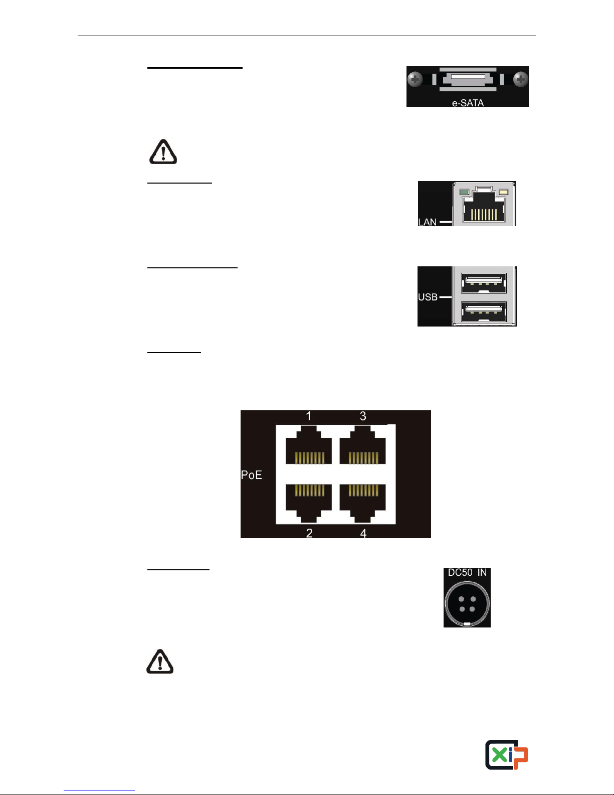
e-SATA (Optional)
Users can connect an e-SATA storage device to
expand the storage size of the NVR. Note that this
port is only available for 4CH models.
NOTE: The NVR MUST be shutdown before
detaching the e-SATA storage device.
LAN (RJ-45)
The NVR is capable of networking and it allows
videos to be viewed over the LAN network or the
internet via the IE browser.
USB Connectors
The USB connectors are provided for users to
connect external USB devices to the unit, such as
ThumbDrive®, or an USB mouse.
PoE Ports
Each PoE port is for direct connection to an IP camera to provide power
and network with just one RJ-45 cable.
Power Jack
Connect the power supply cord and the power
adaptor shipped with the NVR.
NOTE: Use of other power supply cords or power adaptors may cause
overloading.

NVR User’s Manual
10
3. General System Setup
Before operating the NVR, some general configuration should be setup first.
The following subsections will introduce general configuration of the NVR.
The regular displayed OSD information and its displayed positions are shown
as the following figure. Title of the channel will be displayed on the top-center
of the gird, either in full-screen mode or in multiple-window mode. The current
operation status and date/time information will be displayed in the status bar
at the bottom of the screen. Move the cursor to any status bar icon and its
description will be displayed. Refer to the Setup Guide for a list of status bar
icons and their descriptions.
CH1
CH3
CH2
CH4
2013/12/09 04:31:22 PM
NVR User’s Manual
11
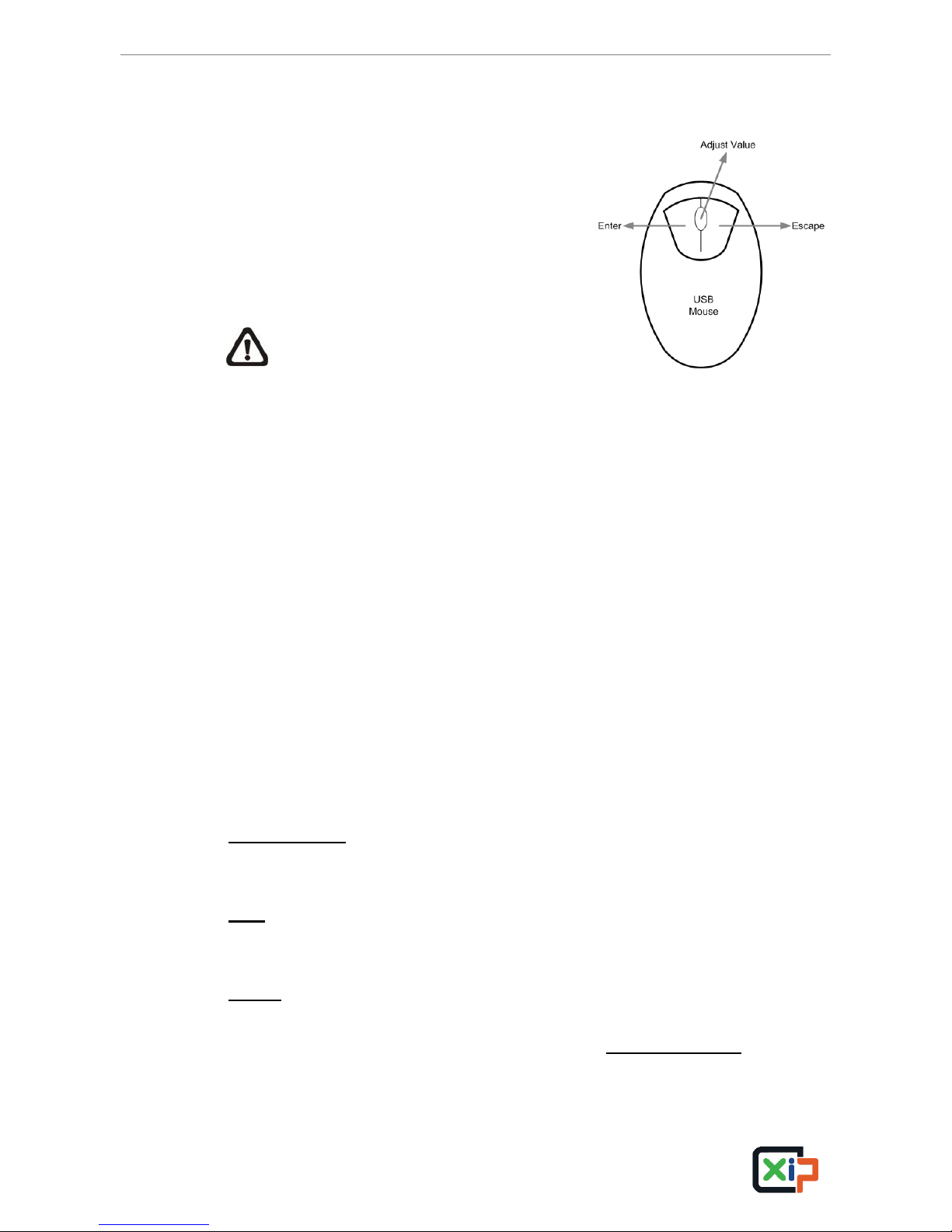
3.1 USB Mouse Operation
A USB mouse must be connected in order to
operate the NVR. As shown in the figure on
the right, click the left button to select or
“ENTER”. Conversely, click the right button to
exit or “ESC”. The scroll wheel is for adjusting
values.
NOTE: Users can setup preferred
mouse sensitivity level by accessing
the OSD menu <Monitor> <Mouse
Sensitivity>.
Users can click and drag on any camera name to change its position. When
right clicking on any camera name, options are provided for setting positions
of all camera names at once.
In addition, users can also connect an USB keyboard to help operating the
NVR. Refer to the appendix for key definition of the USB keyboard.
3.1.2 Functional Keys
Move the cursor to the right side of the screen and a Live Panel will be
displayed. This section describes the functional icons in the Live Panel.
Please refer to the Setup Guide for the graphical illustration of the functional
icons.
ENTER/ZOOM
In Live full-screen mode, click on this icon to view a 2× zoom image.
ESC
Click on this icon to logout.
MODE
Click on this icon repeatedly to change the display format among full-screen,
4-window, and 9-window. Refer to section Viewing Modes for more
information.
NVR User’s Manual
12
FREEZE
Click on this icon while viewing live image, the live video will be frozen. The
date/time information shown on the monitor will continue updating, as well as
the recording of video. Click on this icon again to return to live video of the
current moment.
SEARCH
In Live mode, click on this icon to enter the Search menu to search and
playback recorded video by date/time or event.
PLAY
Click on this icon to playback recorded video from last suspend time.
NOTE: The video of latest 5~10 minutes cannot be played back
because the video is still saved in the buffer.
SEQ (Sequence)
This icon is for automatic sequence display of predetermined camera orders.
NOTE: This function is only available for 8CH models.
MENU
Click on this icon to enter the OSD setup menu.
DOME
Click on this icon to enter Dome Camera Control mode. Please refer to
Section Dome Control for detailed controlling operation.
CHANNEL
In Live mode, click on the CHANNEL icons to view the corresponding video in
full-screen.
NOTE: Users can also right click the mouse, and the pop-up menu
provides some similar functions such as Mode List, Mode, Freeze,
Search, Fast PB, Sequence, Menu and Dome.
NVR User’s Manual
13
3.2 Enter OSD Setup Menu
The configuration of the NVR can be customized through the intuitive
Graphical User Interface (GUI) OSD setup menu. Collaborating with a USB
mouse, setting up the NVR can be easy as operating on a PC. Click on the
MENU icon in the Live Panel and select an account to login.
The next step is to enter a corresponding password. The preset password for
the administrator account “admin” is “1234”.
NOTE: It is strongly suggested to change the preset password to
prevent unauthorized access to the unit.
An icon displayed at the status bar will show the authority level of the account.
Under logout condition, the icon will be a guest icon. When an account is
logged in, its authority level number (1~8) will be shown.
Before completely logout, other functions can still be accessed. There are two
ways to logout: manually logout by clicking on the ESC icon in the Live Panel,
or auto logout when users have not accessed the NVR for a preset period of
time (default 5 minutes) at Live/Menu mode.
3.2.1 User Management
The NVR provides the option to create up to seven sets of usernames and
passwords with customized authority, excluding the preset “admin” account.
From the Main Menu, select <System> <User Management> and the
menu is as the following.
User Management
Password Protection
Auto Logout
Account Setup
Permissions Setup
Load Default Setting
On
300 Sec
No
Password Protection
Select <On> to request username and password for accessing functions
listed in Authority Setup menu, or select <Off> to allow free access.
NVR User’s Manual
14
Auto Logout
Select the duration of time to auto logout after no operation is performed.
Account Setup
Setup customized account, password, and privilege level in this menu. The
account is case sensitive. The privilege level rank from level 1~8, and level 8
has highest privilege. Alternatively, select <Disable> to stop using the account.
A second password can also be specified, if required.
NOTE: The username and privilege level of the preset administrator
account “admin” cannot be changed.
Permissions Setup
Setup the allowed authority level for accessing the functions listed in this
menu. In accordance with users’ privilege level defined in <Account Setup>,
the authority level here also ranks from levels 1~8, with level 8 as the highest
level. Users will be able to access any function that is set to their equivalent or
lower level. Alternatively, select <DISABLE> to allow free access.
NOTE: The “Menu Access” cannot be set to <Disable>.
When the account does not have authority to access certain functions, an
error message will be displayed on the screen.
Load Default Setting
Select <Yes> to load the default setting.

NVR User’s Manual
15
3.3 Reboot and Shutdown
If the NVR must be shutdown for any reason, please follow the proper
shutdown procedures to avoid damaging the NVR.
Click on the Menu icon and users can either choose <Shutdown> to quick
shutdown the NVR, or choose <Menu> to enter the Shutdown menu. The
following menu will be displayed.
Shutdown
Power Off
Reboot
Auto Rebooting
Rebooting Time
Off
AM 12:00
Power Off
Select this item to shutdown the NVR. Do not remove the power source until
the NVR is completely off.
Reboot
Select this item to reboot the NVR. The login screen will be displayed after the
NVR is completely restarted.
Auto Rebooting
The NVR can be set to reboot automatically once a day/week at a
predetermined time, in order to keep the NVR system more stable. Select
<Off> to disable the auto rebooting function.
Rebooting Time
If the auto rebooting function is enabled, select a desired time to perform the
auto rebooting function.

NVR User’s Manual
16
3.3.1 HDD Auto Scan
When the NVR found file system error while recording, the NVR will reboot
and HDD auto scan will be initiated. If by any chance auto scan failed, the
HDD will need to be formatted.
NOTE: If users wish to initiate HDD auto scan function for abnormal
power loss as well, enter the OSD setup menu via an authorized
account and access <Database> to set <Repair On Power Loss> to
<On>. HDD auto scan will be initiated every time the NVR powers on if
it previously loss power abnormally or if there is file system error.
Read the following troubleshooting to finish the auto scanning process.
Skip Auto Scan: During the scanning process, users can click to skip the
process.
Time Expired: When the scanning process took more than predetermined
time (3hrs for 1TB HDD, 6hrs for 2TB HDD, etc.), the scanning process is
treated as failed and will be automatically terminated. The NVR will reboot.
Format HDD: If the scanning process is failed, users will be prompted to
confirm format of the HDD with error. When users confirmed to format the
HDD with error, login of an authorized account is required if password
protection is enabled. If users select cancel or do not respond within 5
minutes, the HDD with error will be marked as a NG HDD. A NG HDD will
not be counted as a part of the NVR’s database. It will just stay there doing
nothing.
Recover NG HDD: Enter the OSD setup menu via an authorized account
and access <Database>. Then select <Internal Disks> and find the NG
HDD from the list. Under <Action> column, select <Format> to format the
NG HDD. Then select <Add> to add the formatted HDD to the database.
NOTE: The above actions will be recorded in the system log data.
NVR User’s Manual
17
3.4 System Date/time Setting
Users can set the current date, time and other OSD parameters in Date/Time
menu (under System setup menu). The login account should have authority to
access the System menu. In OSD setup menu, select <System>, and then
select <Date/Time> to access the Date/Time menu; the menu displays as
follows.
Date/Time
Date
Time
Time Zone
Date/Time Display
Date Display Mode
Time Display Mode
Daylight Saving Time Setup
Network Time Protocol Setup
2010/12/07
PM 10:39:26
Off
1 Row
Y/M/D
12 HR
3.4.1 Set Date/time
Set Date/time
Select <Date> or <Time> for adjusting the settings. Click at the target position
and click on the UP/DOWN arrow buttons to change the value in the selected
field.
NOTE: The new date/time setting applies to videos recorded after the
change. The date and time of previously recorded videos will not be
altered.
NOTE: If time settings have to be changed in any case, it is strongly
recommended to format the HDDs to avoid database corruption.
Date/time Display
Users are allowed to set the time OSD displays in 1 row or 2 rows.
Date Display Mode
This item allows user to set the OSD display type of the date. There are three
options to select from: <Y/M/D>, <M/D/Y> or <D/M/Y>. “Y” represents “Year”,
“M” represents “Month” and “D” represents “Day”.
Time Display Mode
User can set the time format to <12 HR> or <24 HR>.
NVR User’s Manual
18
3.4.2 Daylight Saving Time
Daylight Saving Time
The item is for people who live in certain regions to observe Daylight Saving
Time. Select <On> to enable, or <Off> to disable the function. If the function is
disabled, the DST Start/End time and DST Bias will be grayed out and cannot
be accessed.
NOTE: If this function is enabled, the date/time information will be
shown on the screen with a DST icon when playing back recorded
video or searching video in the event list. “S” indicates summer time
and “W” indicates wintertime.
DST Start/End
These items are used to program the daylight saving duration. Click at the
target position and click on the UP/DOWN arrow buttons to change the value.
DST Bias
This item allows user to set the amount of time to move forward from the
standard time for daylight saving time. The available options are in minutes.
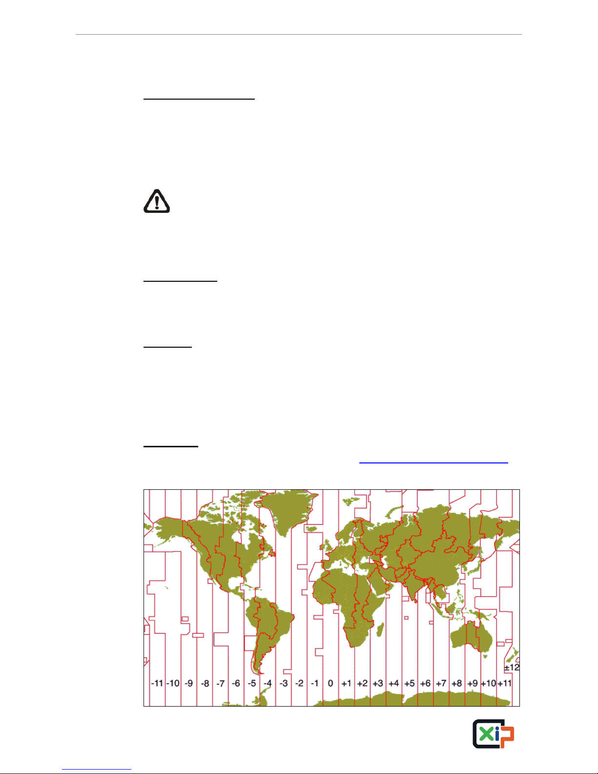
3.4.3 Network Time Protocol Setup
Time Zone
Select users’ current time zone. Please visit www.greenwichmeantime.com to
find out the correct local time zone, or refer to the following figure.

NVR User’s Manual
19
NOTE: The <Time Zone> must be set to the correct local time zone or
the <Network Time Protocol Setup> will not be accessible.
Network Time Protocol Setup
After time zone is selected, <Network Time Protocol Setup> option will be
available. Select <Network Time Protocol Setup> to set the NTP server.
The default NTP server is time.nist.gov. Users can always change to any
other NTP servers. A list of IP addresses of the NTP servers is listed below.
129.6.15.28
129.6.15.29
132.163.4.101
132.163.4.102
132.163.4.103
128.138.140.44
192.43.244.18
131.107.1.10
69.25.96.13
206.246.118.250
208.184.49.9
64.125.78.85
207.200.81.113
64.236.96.53
68.216.79.113
After the time server is set, select <Yes> for <Manually Time Sync> to sync
the time immediately. The time sync can also be updated periodically. Select
<On> for <Automatically Time Sync>, and the time will be automatically
synced once an hour.
3.5 IP Camera Setting
IP cameras can be connected via network. For models with PoE ports, when
IP cameras with the Nx Series protocol are connected to PoE ports, settings
of the IP cameras will be automatically retrieved if the PnP function is enabled.
If users wish to connect IP cameras with other supported protocols to the PoE
ports, disable the PnP function and setup the related settings in the
<Camera> setup menu. The <Camera> setup menu will be shown as below.
Camera
IP Camera Select
IP Camera Name
IP Camera Covert
Enable PnP
Device Search
Hostname/IP
Model
Connection Setup
Device Setup
Activated
Status
Copy Settings
CH01
CH01
Off
On
X.X.X.X
Nx Series
No

NVR User’s Manual
20
NOTE: If the IP camera is already activated, items <Device Search>,
<Hostname/IP>, <Model>, <Connection Setup>, and <Copy Settings>
will be grayed out and cannot be accessed.
NOTE: The maximum throughput of 4CH / 8CH models is 20Mbps /
40Mbps. Therefore, the maximum throughput for each channel is
5Mbps.
3.5.1 IP Camera Information
IP Camera Select
Choose an IP camera at this item to edit its settings.
IP Camera Name
Access this item to input a name of the IP camera to be shown on the monitor.
IP Camera Covert
If users want to hide the live image of the IP camera, select <On>. Note that
the display in the remote monitoring software will also be hidden. Otherwise,
select <Off>, the live image will be shown on the monitor.
Enable PnP
The preset is <On> that enabled the plug and play function via the PoE port
connection. Users need to select <Off> to be able to connect the IP camera
via internet.
Device Search
Select this item to automatically search for IP cameras installed in the same
LAN network. If the IP cameras are ONVIF devices, “Brand Name/Onvif” will
be shown under the “Brand” column.
Hostname/IP
Users can input the hostname or IP address of the IP camera here, for
example 192.168.1.123.
Please obtain IP address of the connecting IP camera. Alternatively, if the
connecting IP camera is installed in the same LAN as the NVR, users can
look for it by device search.
 Loading...