


XP3-BD User Manual Page 2 of 30 MANUL008R2V1
XP3-BD User Manual
Index Page
Chapter 1 Configuration of the BD-Board
1-1 Configuration 3
Chapter 2 AI and temperature sampling board XP3-2AD2PT-BD
2-1 General 5
2-2 Specs 6
2-3 External installations and connections 7
3-4 Assignment of input ID 8
2-5 Working Mode settings 9
2-6 Control settings 10
2-7 Application of PID output value 10
2-8 Programs 11
Chapter 3 K type thermo coupling temperature PID board XP3-2TC-P-3D
3-1 General 13
3-2 Specs 14
3-3 External installations and connections 15
3-4 Assignment of input ID 17
3-5 Working Mode settings 18
3-6 Control Speciality 19
3-7 Programs 20
Chapter 4 Analogue AI/AO temperature sampling board XP3-2PT2ADIDA-
BD
4-1 General 21
4-2 Specs 22
4-3 External installations and connections 23
4-4 Assignment of input ID 24
4-5 Working Mode settings 25
4-6 Control Speciality 26
4-7 Programs 27
XP3-BD User Manual Page 3 of 30 MANUL008R2V1
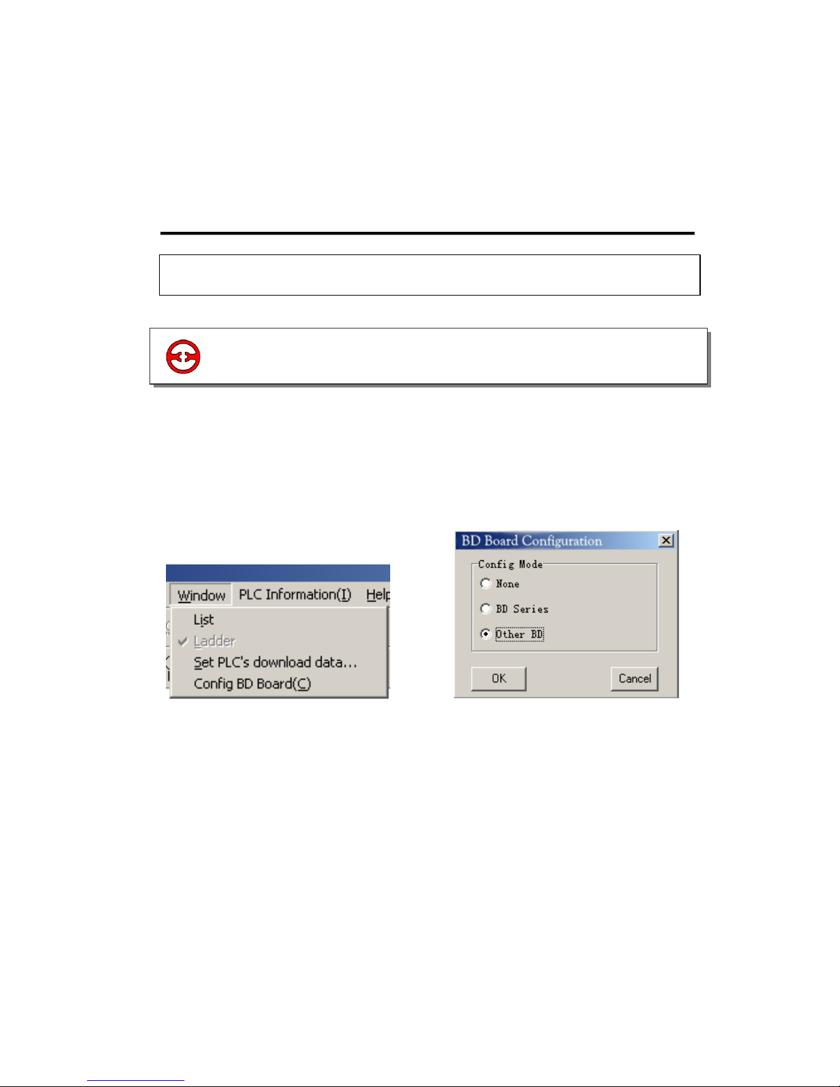
1 Configuration of the BD-Board
1. Install BD correctly on the main unit;
2. Then connect the model online via XCP edit tool, in the “Window” menu, choose “Config
BD Board(C)” (Image 1).
3. Click it, in the “Config BD Board(C)” dialog box, choose “Other BD” (Just as shown in graph
and click “OK” to download the program.
Image 1 Image 2
1-1 Configuration
1-1.Configuration

XP3-BD User Manual Page 4 of 30 MANUL008R2V1
2 AI and temperature sampling board XP3-
2AD2PT-BD
2-2.Specs
2-3.External installations and connections
2-1.General
2-5.Working Mode settings
2-6.Control settings
2-4.Assignment of input ID
2-7.Application of PID output value
XP3-BD User Manual Page 5 of 30 MANUL008R2V1
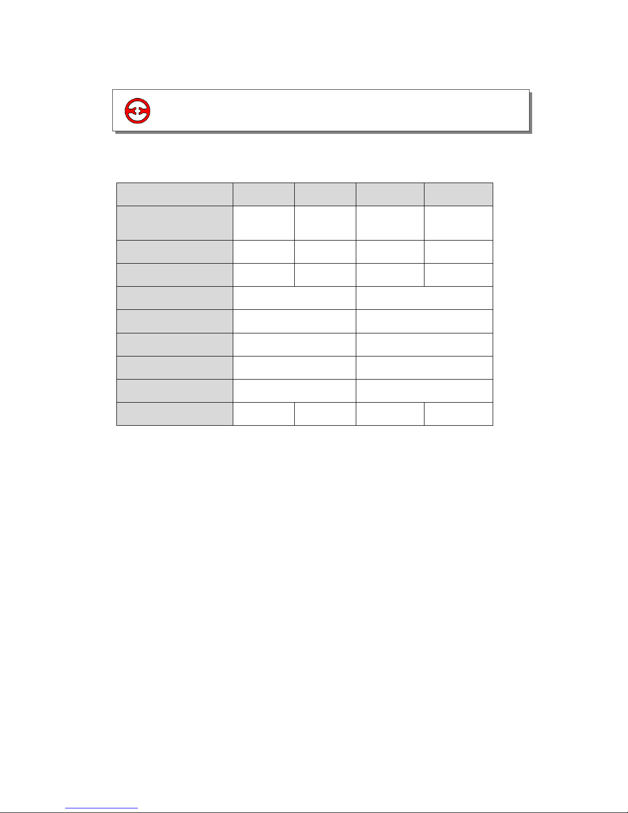
2-1 General
14 bits high precision analogue input.
2 Channel voltage 0/10V, 0/5V
(selectable) analogue input.
2 channels PT temperature testing.
resistor (PT100 two-wire format)
temperature sensor analogue input.

XP3-BD User Manual Page 6 of 30 MANUL008R2V1
Item
Voltage Input
Temperature Input
Analogue Input
Signal
DC: 0 to 5V, 0 to 10V
(Input resistor 300kΩ)
Platinum Resistor PT100
(2-wire format)
Temperature
Testing band
-
-100 to 350 degrees C
Resolution
0.15mV 10/16383
0.1
Digital Output
band
0 to 16383
-1000 to 3500
Integrate
Precision
±0.8% of full scale
Convert Time
15ms × 4 channels
PID Output
Value
0 to K4095
Vacant
Defaulted
Value
0
3500
Input
Specialty
Isolation
No isolation between each channel of PLC
Used points
0 point (As operated via data register, so the used points are not limited
by PLC’s max control points)
2-2 Specs
XP3-BD User Manual Page 7 of 30 MANUL008R2V1
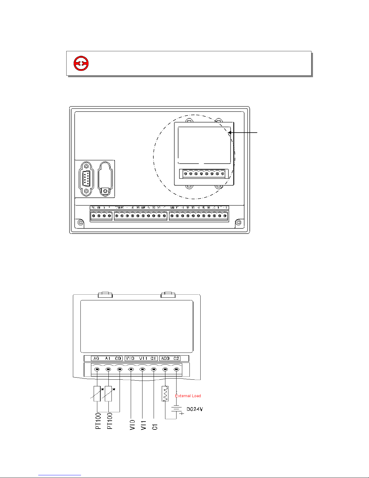
Board’s install
position
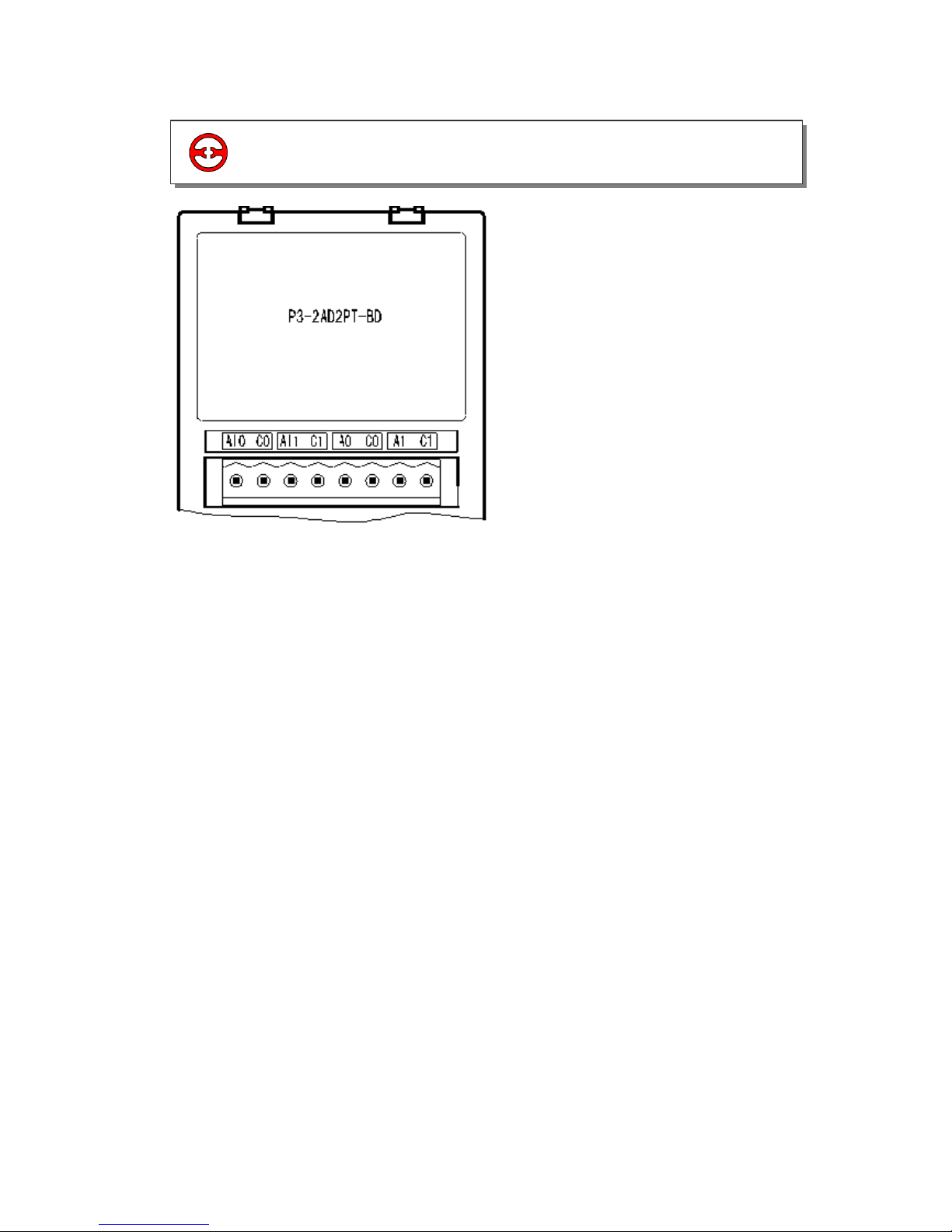
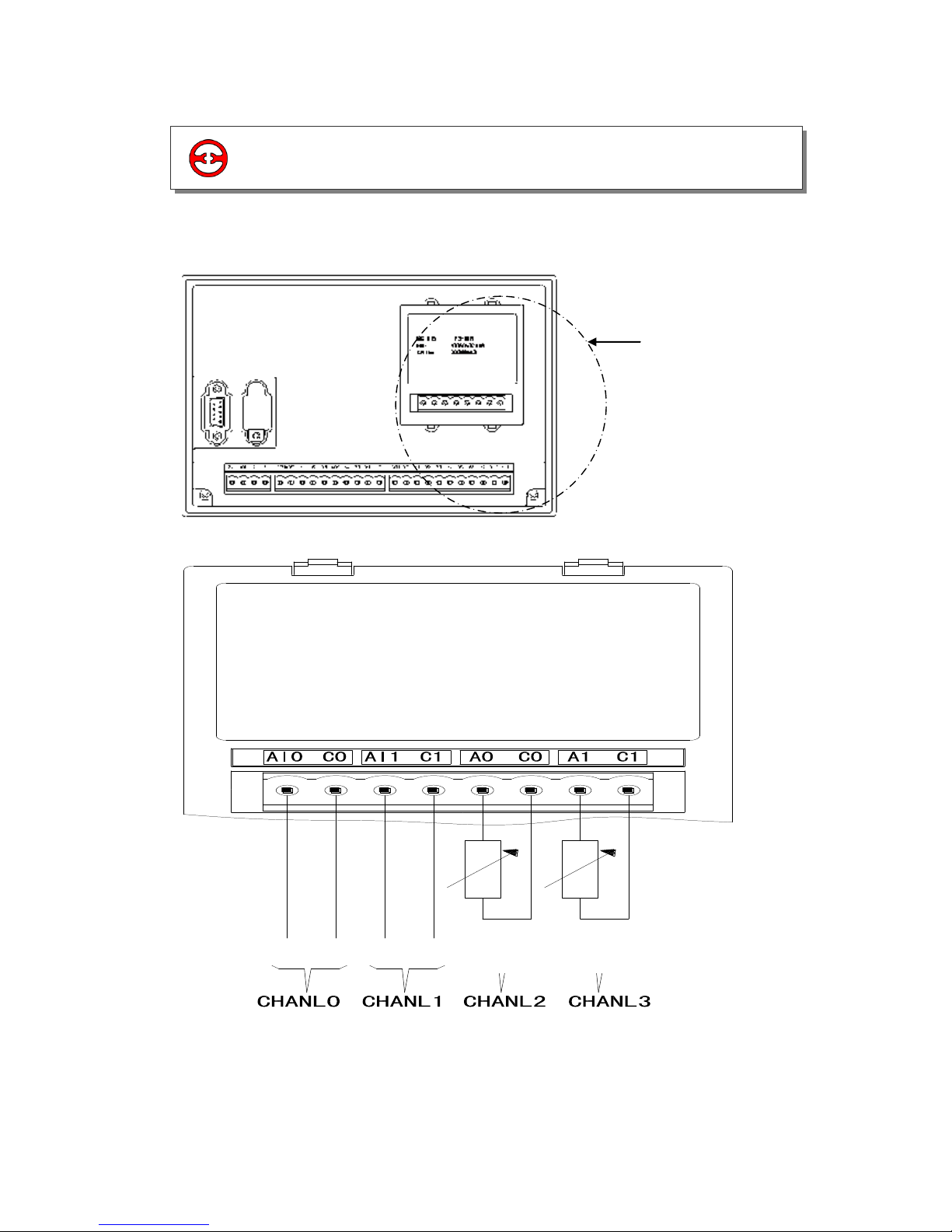
1) The Installation of Board:
Open the board’s cover at the back of XP3 (As shown in the following image); install it according
to the pin arrangement. Then fix it with screws, close the cover.
2) Connection: See the following diagram
PT100
PT100
V-
V+
V-
V+
2-3 External installations and connections
XP3-BD User Manual Page 8 of 30 MANUL008R2V1
This BD board does not use standard I/O units memory addresses, the converted data will be
directly sent into PLC register. The channels correspond to the PLC register ID:
Channel
0CH
1CH
2CH
3CH
AD signal/Temperature
value
ID1000
ID1001
ID1002
ID1003
PID output value
ID1004
ID1005
ID1006
ID1007
Set the target value
QD1000
QD1001
QD1002
QD1003
Kp
QD1004
QD1009
Ki
QD1005
QD1010
Kd
QD1006
QD1011
Diff
QD1007
QD1012
Dead Band
QD1008
-
Start/Stop
Y1000
Y1001
Y1002
Y1003
Note:
1. PID value: PID output value:0 to 4095.
2. Kp: proportion parameter
3. Ki: Integral parameter.
4. Kd: Differential parameter.
5. Diff: Control proportion band.
6. Control coil’s status: Y1000/Y1001 (0 = means stop PID control, 1 = means run PID control
Description:
0CH and 1CH are AD input channels.
2CH and 3CH are PT100 input channels.
Kp: proportion parameter.
Ki: Integral parameter.
Kd: Differential parameter.
Diff: Control band.
Control Band Diff: Carry on PID control in the assigned band, beyond the band, don’t carry
on PID control
Start Signal (Y): PID control is closed when Y is 0, open PID control when Y is 1.
Dead Band “Dead Band”: Compare the current PID output value with the preceding PID
output value. If their difference is less than the set Dead Band, the module will abandon the
current PID output value; still transferring the preceding PID output value to PLC main unit.
2-4 Assignment of input ID
XP3-BD User Manual Page 9 of 30 MANUL008R2V1
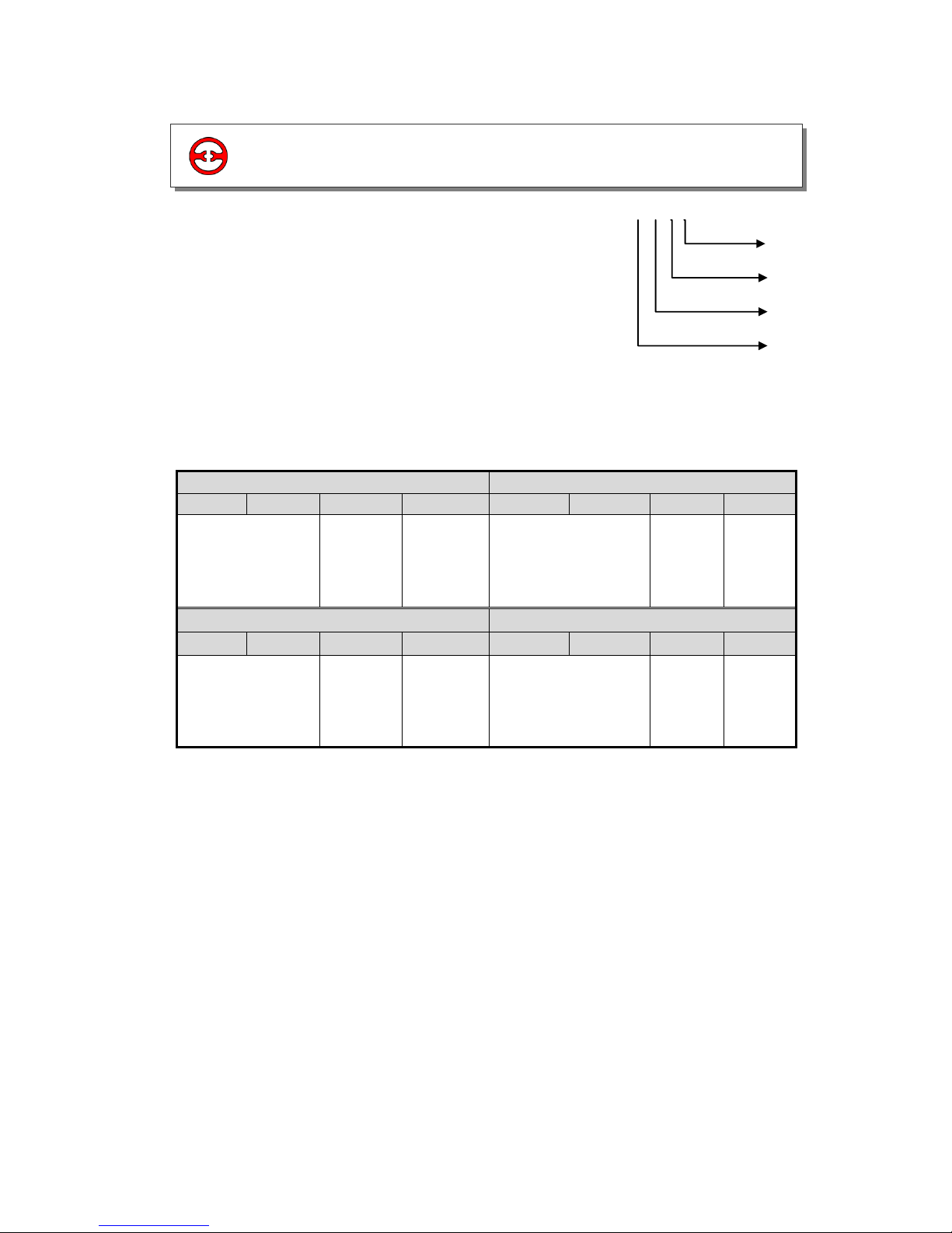
2) Each channel’s working mode is assigned by the four bits of the corresponding register, each
bits definition is shown below:
Register FD8306:
1. Usage of four parameters: Proportion parameter (Kp), integral parameter (Ki), differential
parameter (Kd), control proportion band (Diff).
2. Parameter P is proportion parameter, mainly reflect system’s wrap, when system wrap
appears, carry on control immediately to decrease the wrap.
3. Parameter I is integral parameter, mainly used to remove net difference, improve the systems
no-difference degree
4. Parameter D is differential parameter; mainly used to control the signal’s change trend,
decrease system’s shake.
5. Temperature control proportion band means: in the assigned band, carry on PID control,
beyond the band, do not carry on PID control.
CH1
CH 0
Bit7
Bit6
Bit5
Bit4
Bit3
Bit2
Bit1
Bit0
00: 1/2 filter
01: not filter
10: 1/3 filter
11: 1/4 filter
-
0:0~10V
1:0~5V
00: 1/2 filter
01: not filter
10: 1/3 filter
11: 1/4 filter
-
0:0/10V
1:0/5V
CH3
CH 2
Bit15
Bit14
Bit13
Bit12
Bit11
Bit10
Bit9
Bit8
00: 1/2 filter
01: not filter
10: 1/3 filter
11: 1/4 filter
-
-
00: 1/2 filter
01: not filter
10: 1/3 filter
11: 1/4 filter
-
-
2-5 Working Mode settings
1) Expansion’s input has voltage 0/5V and 0/10V. These
two modes and filter form to select. Set via special
FLASH data register FD8306 in PLC.
Refer to the graph (right) each register set the 4
channels’ modes, each register has 16 bits. From low bit
to high bit, each 4 bits set one channel mode.
FD8306 H O O O O
0CH
1CH
2CH
3CH

XP3-BD User Manual Page 10 of 30 MANUL008R2V1
1. Usage of four parameters: Proportion parameter (Kp), integral parameter (Ki), differential
parameter (Kd), control proportion band (Diff)
Parameter P is the proportion parameter.
Parameter I is the integral parameter.
Parameter D is differential parameter
Temperature Control Band Means: in the assigned band, to carry out PID control.
PID Temperature Control Curve is Shown Below:
Note:
Each parameter’s reference value: Kp=20/100, Ki=5/20, Kd=200~500, DIFF=100/200.
This reference value only for normal condition, according to the locale detail condition, each
reference value could be beyond the band.
When using PID, the BD board will perform heating control with a cycle of 2 Seconds.
This modifies the output value based on the PID control.
2-6 Control settings
2-7 Application of PID output values

XP3-BD User Manual Page 11 of 30 MANUL008R2V1
E.g.1: Real time readings of the AD value of CH0, and then carries on PID parameters setting
with CH0, then read the PID output value.
MOV K800 QD1000
MOV ID1000 D10
M8000
END
MOV K30 QD1004
MOV K5 QD1005
MOV K500 QD1006
MOV K150 QD1007
MOV K200 QD1008
MOV ID1004 D1000
Y1000
M8
2-8 Programs
Write CH0’s input value into D10
Set CH0’s value as 800
Set CH0’s Kp as 30
Set CH0’s Ki as 5
Set CH0’s Kd as 500
Set CH0’s Diff as 150
Set CH0’s Death as 200
Write CH0’s PID output value into
D1000
Start/stop PID adjustment of CH0

XP3-BD User Manual Page 12 of 30 MANUL008R2V1
E.g.2. PID temperature control example
MOV K800 QD1002
MOV ID1006 D1000
MUL D1000 K200
DDIV D1100 K4095
D1100
D1200
M8000
M8000
T200 K200
T200
T200 D1200
≤
Y3
Y1000
M10
END
MOV K30 QD1009
MOV K5 QD1010
MOV K500 QD1011
MOV K150 QD1012
D1100>K0
T200 is 10ms timer
Convert PID output value (0/4095) to be
value of 0/200
Via ON/OFF of Y3, carry on PID
temperature adjustment
Stop/start CH2
Set CH2’s value as 800 (80 degrees)
Set CH2’s Kp as 30
Set CH2’s Ki as 5
Set CH2’s Kd as 500
Set CH2’s Diff as 150

XP3-BD User Manual Page 13 of 30 MANUL008R2V1
3 K Type thermo coupling temperature PID
board XP3-2TC-P-3D
3-1. General
3-2.Specs
3-3.External installations and connections
3-4.Assign input/output ID
3-5.Working Mode settings
3-6.Control speciality
3-7.Programs
3-1 General
Analogue input used by thermocouple (K type) temperature sensor
2 channels input, 2 channels output
2 groups PID parameters
Cold terminal compensate circuit inside
Resolution is 0.1

XP3-BD User Manual Page 14 of 30 MANUL008R2V1
Item
Content
Analogue Input Signal
Thermocouple K type
Input Points
2 points
Temperature Testing Band
0 to 970°C
Digital Output Band
0~9700, 16 bits binary
Output Points
2 points
Output Format
NPN collector open circuit transistor output
Control Precision
0.4°C
Resolution
0.1°C
Synthesis Precision
±0.8% (Relative max value)
Conversion Speed
45ms × 2 channels
Analogue Power
DC24V±10%, 50mA
3-2 Specs

XP3-BD User Manual Page 15 of 30 MANUL008R2V1
Install Position of
Expansion Board
Installation Method of Expand Board:
1. Open the expansion cover behind XP3 (See the following diagram), then install according to
the pin and fix with screws.
2. Connection Method
3-3 External installations and connections

XP3-BD User Manual Page 16 of 30 MANUL008R2V1
Output terminals:
Transistor output terminals - please choose DC5V to 30V-regulated power.
Circuit insulation:
Between programmable controller’s interior circuit and output transistor, use optical coupling
device to insulate. Each public module is divided separately
Response time:
The time from PLC drive optical coupling device to transistor ON/OFF is not more than 0.2ms.
Output current:
Each point’s current could be 0.8A, but to restrict temperature increasing, please use as 1.2A
per 4
Open circuit leakage current:
Below 0.1mA
The Output Current is Shown Below:

XP3-BD User Manual Page 17 of 30 MANUL008R2V1
This BD expansion does not use I/O unit, the converted data is directly sent into PLC register,
also add two extra output points. Extra outputs do not include normal system’s I/O output.
Channels correspond to the PLC register ID:
Channel
Current
Temperature
Set
Temperature
Kp
Ki
Kd
Diff
Start/stop
0CH
ID1000
QD1000
QD1
001
QD1
002
QD1
003
QD1
004
Y1000
1CH
ID1001
QD1005
QD1
006
QD1
007
QD1
008
QD1
009
Y1001
Note:
1. Kp: proportion parameter, Ki: integral parameter, Kd: differential parameter; Diff: control
proportion band.
2. Control coil’s status (Y1000/Y1001): 0 = means close PID control, 1 = means start PID
control.
3. Expansion’s input has voltage 0/5V or 0/10V these two modes and filter form to select. Set
via set the 4 channels’ mode, each register has 16 bits. From low bit to high bit, each 4 bits set
one channel’s mode
3-4 Assign input/output ID

XP3-BD User Manual Page 18 of 30 MANUL008R2V1
2) Temperature Control Cycle
Temperature Control Cycle: When carry on PID adjustment, the output terminals carry on
heating according to the duty cycle got by PID output value, this period is called Temperature.
Control Cycle
CH1
CH0
Bit7
Bit6
Bit5
Bit4
Bit3
Bit2
Bit1
Bit0
- - -
0:2 Sec.
- - -
0:2 Sec.
1:20 Sec.
1:20 Sec.
FD8306 H O O O O
0CH
1CH
3-5 Working Mode settings
1) Set the expansion’s working mode via special FLASH
data register FD8306 in PLC. Refer to the graph by the
right, each register has 16 bits, from low bit to high bit,
every 4 bits confirm 1 channel’s mode.

XP3-BD User Manual Page 19 of 30 MANUL008R2V1
1. Usage of Four Parameters:
Proportion parameter (Kp), integral parameter (Ki), differential
parameter (Kd), control proportion band (Diff)
Parameter P is the proportion parameter:
Parameter I is the integral parameter, mainly used to remove net difference.
Parameter D is the differential parameter, mainly used to control signal’s change trend.
Temperature Control Band Means: in the assigned band, to carry out PID control,beyond
the band does not carry out PID control.
2. Temperature Control Cycle:
When carrying out PID adjustment, the output will carry on
heating according to the duty cycle got by PID output value, this period is called
Temperature Control Cycle.
3. Control Specialties:
The band of the PID adjustment is: (QD-Diff QD + Diff), when the temperature is lower
than QD-Diff, controller goes on heating, when temperature is higher than QD + Diff, the
controller will stop heating.
The Control Curve of PID is Shown Below:
Each parameter’s reference value: Kp=20/100, Ki=5/20, Kd=200/500. DIFF=100~200
This reference value only for normal condition,according to the locale detail condition, each
reference value could be beyond the band.
3-6 Control specialities

XP3-BD User Manual Page 20 of 30 MANUL008R2V1
Program with CH0
K800MOV QD1000
K500MOV QD1003
K5MOV QD1002
K30MOV QD1001
M8000
END
K150MOV QD1004
Y1000
M0
3-7 Programs
Set value in CH0 as 800 (80 degrees)
Set CH0’s Kp as 30
Start/stop CH0
Set CH0’s Ki as 5
Set CH0’s Kd as 500
Set CH0’s Diff as 150
(i.e., carry on PID operation at
650)

XP3-BD User Manual Page 21 of 30 MANUL008R2V1
4 Analogue AI/AO temperature sampling
board XP3-2PT2ADIDA-BD
4-1. General
4-2.Specs
4-3.External installations and connections
4-4.Assignment of input ID
4-5.Working Mode settings
4-6.Control settings
4-7.Programs

XP3-BD User Manual Page 22 of 30 MANUL008R2V1
4-1 General
14 bits high precision analog input
10 bits high precision analog output
2 channels voltage 0/10V or 0/5V (selectable)
analog input
2 channels PT temperature testing resistor
(PT100 2-wire format) temperature sensor
analog input

XP3-BD User Manual Page 23 of 30 MANUL008R2V1
Item
Voltage Input
Temperature Input
D/A output
Analogue
Input Signal
DC: 0to 5V, 0 to 10V
(Input Resistance
300kΩ)
Platinum resistor PT100
(2-wire format)
Digital Input
band
10 bits Binary
(0/1023)
Analogue
Output band
0/20mA, 4/20mA
Temperature
Testing
band
-100 to 350°C
Distinguish
Ratio
0.15mV 10/16383
0.1ºC
1/1023
Digital Output
band
0 to 16383
-1000 to 3500
Integrate
Precision
±0.8% of the full scale
Conversion
Time
15ms × 4 channels
PID output
value
0 to K4095
Vacant
defaulted
value
0
3500
-
Input/output
Specialty
Isolation
No isolation among PLC’s each channel
Used I/O
0 point (because it is operated via data register, so it is not limited by
master PLC’s standard I/O control points)
4-2 Specs
XP3-BD User Manual Page 24 of 30 MANUL008R2V1
Board’s install
position
1. Installation method of the expansion board:
Open the board’s cover at the back of XP3 (As shown in the following graph), and then
install it according to the pin arrangement. Then fix it with screws, close the cover.
2. Connection format: As shown in the following graph:
Note:
Module’s 0/20mA or 4/20mA output needs 24V power supplier from outside. According to
the QD value, the module adjusts the signal’s current. However, the model itself doesn’t
generate current.
4-3 Extension installations and connections

XP3-BD User Manual Page 25 of 30 MANUL008R2V1
This BD board does not use I/O units, the converted data will be sent directly into the PLC
register. The channel’s corresponding PLC register ID is:
Channel
0CH
1CH
2CH
3CH
AD signal/Temperature
value
ID1000
ID1001
ID1002
ID1003
PID output value
ID1004
ID1005
ID1006
ID1007
Set the target value
QD1001
QD1002
QD1003
QD1004
D/A Output Value
QD1000
Kp
QD1005
QD1009
Ki
QD1006
QD1010
Kd
QD1007
QD1011
Diff
QD1008
QD1012
Dead Band
--
QD1013
Start/Stop
Y1000
Y1001
Y1002
Y1003
Note:
1. Both 0CH and 1CH are PT input channels; 2CH and 3CH are AD input channels
2. Kp: proportion parameter
3. Ki: Integral parameter
4. Kd: Differential parameter
5. Diff: Control band
Control band
6. (Diff): Carry on PID control in the assigned band;
7. Start Signal (Y): Close PID control when Y is 0, open PID control when Y is 1
8. Dead Band (Dead Band): Compare the current PID output value with the preceding PID
output value. If their difference is less than the set Dead Band, the module will not use the
current
PID output value and will transfer the preceding PID output.
4-4 Assignment of input ID

XP3-BD User Manual Page 26 of 30 MANUL008R2V1
Register FD8306:
2) Output channel’s mode setting value is stored in register FD8307 (Low bit); its definition is
CH 1
CH 0
Bit7
Bit6
Bit5
Bit4
Bit3
Bit2
Bit1
Bit0
00: 1/2 filter
01: not filter
10: 1/3 filter
11: 1/4 filter
-
-
00: 1/2 filter
01: not filter
10: 1/3 filter
11: 1/4 filter
-
-
CH 3
CH 2
Bit15
Bit14
Bit13
Bit12
Bit11
Bit10
Bit9
Bit8
00: 1/2 filter
01: not filter
10: 1/3 filter
11: 1/4 filter
-
0:0~10V
1:0~5V
00: 1/2 filter
01: not filter
10: 1/3 filter
11: 1/4 filter
-
0:0~10V
1:0~5V
4-5 Working mode settings
FD8306 H O O O O
0CH
1CH
2CH
3CH
1) Expansion’s input cards have voltage 0/5V,
0/10V these two modes and filter form to
select. Set via special FLASH data register
FD8306 in PLC. Refer to the graph by the
right; each register set the 4 channels’ modes,
each register has 16 bits. From low bit to high
bit, each 4 bits set one channel’s mode

XP3-BD User Manual Page 27 of 30 MANUL008R2V1
shown below:
Register FD8307:
P
a
r
a
m
e
t
e
r
D
i
s
Parameter D is the differential parameter.
Temperature control proportion band: in the assigned band, and will carry on PID
control.
-
D/A channel
Bit7
Bit6
Bit5
Bit4
Bit3
Bit2
Bit1
Bit0
00: 1/2 filter
01: not filter
10: 1/3 filter
11: 1/4 filter
-
-
00: 1/2 filter
01: not filter
10: 1/3 filter
11: 1/4 filter
-
0:0~20m
A
1:4~20m
A
-
-
Bit15
Bit14
Bit13
Bit12
Bit11
Bit10
Bit9
Bit8
-
- - -
-
-

XP3-BD User Manual Page 28 of 30 MANUL008R2V1
1. Usage of Four Parameters: Proportion parameter (Kp), integral parameter (Ki), differential
parameter (Kd), control proportion band (Diff).
Parameter P is the proportion parameter.
Parameter I is the integral parameter, mainly used to remove net difference.
Parameter D is the differential parameter, mainly used to control signal’s change trend.
Temperature Control Band Means: in the assigned band, to carry out PID control, beyond the
band does not carry out PID control.
2. Temperature Control Cycle: When carrying out PID adjustment, the output will carry on
heating according to the duty cycle got by PID output value, this period is called Temperature
Control Cycle
3. Control Specialties: The band of the PID adjustment is: (QD-Diff QD + Diff), when the
temperature is lower than QD-Diff, controller goes on heating, when temperature is higher than
QD + Diff, the controller will stop heating.
The Control Curve of PID is Shown Below:
Each parameter’s reference value: Kp=20/100, Ki=5/20, Kd=200/500. DIFF=100~200
This reference value only for normal condition,according to the locale detail condition, each
reference value could be beyond the band.
4-6 Control specialities

XP3-BD User Manual Page 29 of 30 MANUL008R2V1
The following example is a sample Program & corresponding description:
MOV ID1000 D0
MOV K5 QD1010
M8000
END
MOV ID1001 D2
MOV ID1002 QD1004
MOV ID1003 D4
MOV K30 QD1009
MOV K500 QD1011
Y1003
M8
MOV K150 QD1012
MOV K200 QD1013
MOV ID1007 D10
M8000
DIV D10 D12K4
MOV D12 QD1000
4-7 Programs
Write channel 0 (input temperature) into D0
Write channel 1 (output temperature) into D2
Treat CH2 (Pressure setting 0/10V) as the
set value in CH3
Write CH3 (Pressure Feedback) into D4
Set AD Channel’s Kp as 30
Set AD Channel’s Ki as 5
Set AD Channel’s Kd as 500
Set AD Channel’s Diff as 150
Set AD Channel’s Dead band as 200
Start/stop PID adjustment of CH3
Write PID output value of CH3 into D10
Change PID output range from 0/4095 as
0/1023
Convert PID output to be 0/10V output, to
control the inverter’s rotation speed
XP3-BD User Manual Page 30 of 30 MANUL008R2V1
Documentation Reference
Document Number
Revision Date
MANU
L008
R2
V1
05/07/2011
XINJE IS A REGISTERED TRADEMARK OF XINJE ELECTRICAL CO.LTD.
REPLICATION OF THE INFORMATION CONTAINED WITHIN THIS DOCUMENT
WITHOUT PRIOR NOTIFICATION AND AGREEMENT IS PROHIBITED.
Engineered and supplied by:
International partners with:
Web: www.listo-ltd.com
www.xinje-support-centre-listo.com
E-mail: support@listo-ltd.com
Please consider the environment before printing
this document
 Loading...