


XP3-BD User Manual Page 2 of 30 MANUL008R2V1
XP3-BD User Manual
Index Page
Chapter 1 Configuration of the BD-Board
1-1 Configuration 3
Chapter 2 AI and temperature sampling board XP3-2AD2PT-BD
2-1 General 5
2-2 Specs 6
2-3 External installations and connections 7
3-4 Assignment of input ID 8
2-5 Working Mode settings 9
2-6 Control settings 10
2-7 Application of PID output value 10
2-8 Programs 11
Chapter 3 K type thermo coupling temperature PID board XP3-2TC-P-3D
3-1 General 13
3-2 Specs 14
3-3 External installations and connections 15
3-4 Assignment of input ID 17
3-5 Working Mode settings 18
3-6 Control Speciality 19
3-7 Programs 20
Chapter 4 Analogue AI/AO temperature sampling board XP3-2PT2ADIDA-
BD
4-1 General 21
4-2 Specs 22
4-3 External installations and connections 23
4-4 Assignment of input ID 24
4-5 Working Mode settings 25
4-6 Control Speciality 26
4-7 Programs 27
XP3-BD User Manual Page 3 of 30 MANUL008R2V1
1 Configuration of the BD-Board
1. Install BD correctly on the main unit;
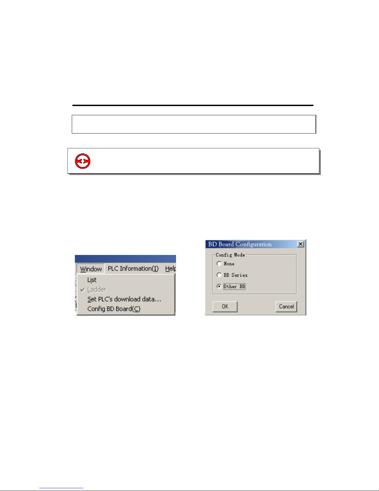
2. Then connect the model online via XCP edit tool, in the “Window” menu, choose “Config
BD Board(C)” (Image 1).
3. Click it, in the “Config BD Board(C)” dialog box, choose “Other BD” (Just as shown in graph
and click “OK” to download the program.
Image 1 Image 2
1-1 Configuration
1-1.Configuration

XP3-BD User Manual Page 4 of 30 MANUL008R2V1
2 AI and temperature sampling board XP3-
2AD2PT-BD
2-2.Specs
2-3.External installations and connections
2-1.General
2-5.Working Mode settings
2-6.Control settings
2-4.Assignment of input ID
2-7.Application of PID output value
XP3-BD User Manual Page 5 of 30 MANUL008R2V1
2-1 General
14 bits high precision analogue input.
2 Channel voltage 0/10V, 0/5V
(selectable) analogue input.
2 channels PT temperature testing.
resistor (PT100 two-wire format)
temperature sensor analogue input.

XP3-BD User Manual Page 6 of 30 MANUL008R2V1
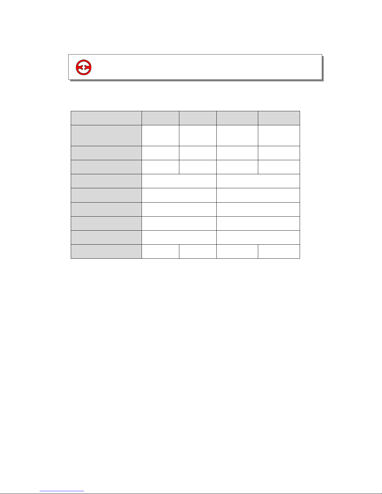
Item
Voltage Input
Temperature Input
Analogue Input
Signal
DC: 0 to 5V, 0 to 10V
(Input resistor 300kΩ)
Platinum Resistor PT100
(2-wire format)
Temperature
Testing band
-
-100 to 350 degrees C
Resolution
0.15mV 10/16383
0.1
Digital Output
band
0 to 16383
-1000 to 3500
Integrate
Precision
±0.8% of full scale
Convert Time
15ms × 4 channels
PID Output
Value
0 to K4095
Vacant
Defaulted
Value
0
3500
Input
Specialty
Isolation
No isolation between each channel of PLC
Used points
0 point (As operated via data register, so the used points are not limited
by PLC’s max control points)
2-2 Specs
XP3-BD User Manual Page 7 of 30 MANUL008R2V1
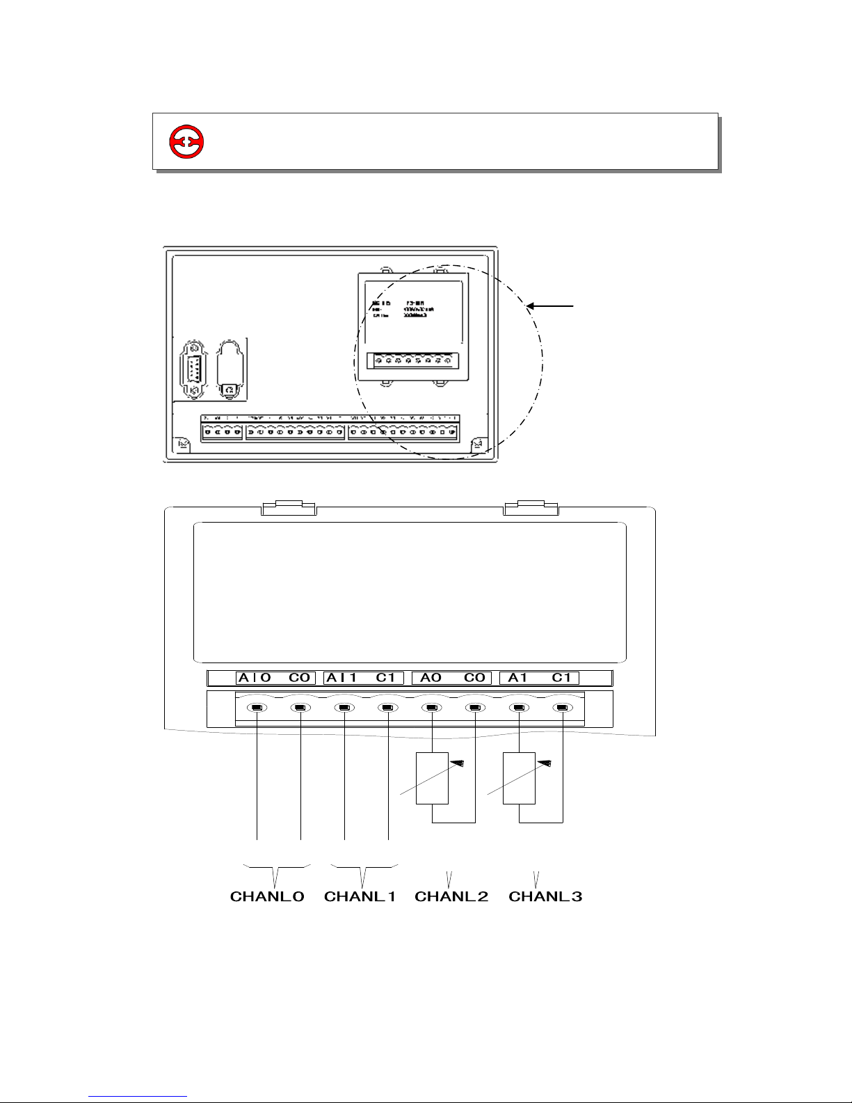
Board’s install
position
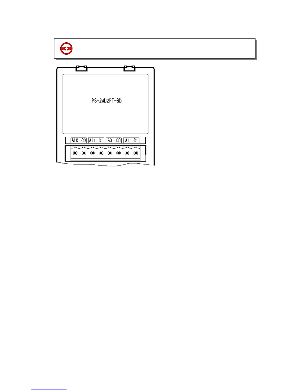
1) The Installation of Board:
Open the board’s cover at the back of XP3 (As shown in the following image); install it according
to the pin arrangement. Then fix it with screws, close the cover.
2) Connection: See the following diagram
PT100
PT100
V-
V+
V-
V+
2-3 External installations and connections
XP3-BD User Manual Page 8 of 30 MANUL008R2V1
This BD board does not use standard I/O units memory addresses, the converted data will be
directly sent into PLC register. The channels correspond to the PLC register ID:
Channel
0CH
1CH
2CH
3CH
AD signal/Temperature
value
ID1000
ID1001
ID1002
ID1003
PID output value
ID1004
ID1005
ID1006
ID1007
Set the target value
QD1000
QD1001
QD1002
QD1003
Kp
QD1004
QD1009
Ki
QD1005
QD1010
Kd
QD1006
QD1011
Diff
QD1007
QD1012
Dead Band
QD1008
-
Start/Stop
Y1000
Y1001
Y1002
Y1003
Note:
1. PID value: PID output value:0 to 4095.
2. Kp: proportion parameter
3. Ki: Integral parameter.
4. Kd: Differential parameter.
5. Diff: Control proportion band.
6. Control coil’s status: Y1000/Y1001 (0 = means stop PID control, 1 = means run PID control
Description:
0CH and 1CH are AD input channels.
2CH and 3CH are PT100 input channels.
Kp: proportion parameter.
Ki: Integral parameter.
Kd: Differential parameter.
Diff: Control band.
Control Band Diff: Carry on PID control in the assigned band, beyond the band, don’t carry
on PID control
Start Signal (Y): PID control is closed when Y is 0, open PID control when Y is 1.
Dead Band “Dead Band”: Compare the current PID output value with the preceding PID
output value. If their difference is less than the set Dead Band, the module will abandon the
current PID output value; still transferring the preceding PID output value to PLC main unit.
2-4 Assignment of input ID
XP3-BD User Manual Page 9 of 30 MANUL008R2V1
2) Each channel’s working mode is assigned by the four bits of the corresponding register, each
bits definition is shown below:
Register FD8306:
1. Usage of four parameters: Proportion parameter (Kp), integral parameter (Ki), differential
parameter (Kd), control proportion band (Diff).
2. Parameter P is proportion parameter, mainly reflect system’s wrap, when system wrap
appears, carry on control immediately to decrease the wrap.
3. Parameter I is integral parameter, mainly used to remove net difference, improve the systems
no-difference degree
4. Parameter D is differential parameter; mainly used to control the signal’s change trend,
decrease system’s shake.
5. Temperature control proportion band means: in the assigned band, carry on PID control,
beyond the band, do not carry on PID control.
CH1
CH 0
Bit7
Bit6
Bit5
Bit4
Bit3
Bit2
Bit1
Bit0
00: 1/2 filter
01: not filter
10: 1/3 filter
11: 1/4 filter
-
0:0~10V
1:0~5V
00: 1/2 filter
01: not filter
10: 1/3 filter
11: 1/4 filter
-
0:0/10V
1:0/5V
CH3
CH 2
Bit15
Bit14
Bit13
Bit12
Bit11
Bit10
Bit9
Bit8
00: 1/2 filter
01: not filter
10: 1/3 filter
11: 1/4 filter
-
-
00: 1/2 filter
01: not filter
10: 1/3 filter
11: 1/4 filter
-
-
2-5 Working Mode settings
1) Expansion’s input has voltage 0/5V and 0/10V. These
two modes and filter form to select. Set via special
FLASH data register FD8306 in PLC.
Refer to the graph (right) each register set the 4
channels’ modes, each register has 16 bits. From low bit
to high bit, each 4 bits set one channel mode.
FD8306 H O O O O
0CH
1CH
2CH
3CH
 Loading...