

Page 1

Xinje Electronic Co.,Ltd.
VB3/VB5/V5
VB3/VB5/V5
VB3/VB5/V5
VB3/VB5/V5 frequency
frequency
frequency
frequency inverter
inverter
inverter
inverter
User
User
User
User manual
manual
manual
manual
No. INV C 01 20081130 204
Page 2

VB3 / V B 5 / V 5
Series Inverter
User M anual
Table
Table
Table
Table of
of
of
of Contents
Contents
Contents
Contents
Preface
Preface
Preface
Preface
———————————————
———————————————
———————————————
———————————————
Safty
Safty
Safty
Safty Precautions
Precautions
Precautions
Precautions
———————————————
———————————————
———————————————
———————————————
Product
Product
Product
Product In
In
In
In troductions
troductions
troductions
troductions
———————————————
———————————————
———————————————
———————————————
Install
Install
Install
Install ation
ation
ation
ation and
and
and
and Wiring
Wiring
Wiring
Wiring
———————————————
———————————————
———————————————
———————————————
Operati
Operati
Operati
Operati on
on
on
on Descriptions
Descriptions
Descriptions
Descriptions
———————————————
———————————————
———————————————
———————————————
Function
Function
Function
Function Parameters
Parameters
Parameters
Parameters
———————————————
———————————————
———————————————
———————————————
Fault
Fault
Fault
Fault D
D
D
D iagnos
iagnos
iagnos
iagnos
is
is
is
is
and
and
and
and Disposal
Disposal
Disposal
Disposal
———————————————
———————————————
———————————————
———————————————
Maint
Maint
Maint
Maint enance
enance
enance
enance
———————————————
———————————————
———————————————
———————————————
Communication
Communication
Communication
Communication Protoc
Protoc
Protoc
Protoc o
o
o
o l
l
l
l
———————————————
———————————————
———————————————
———————————————
Page 3

VB3/ V B 5 / V 5 series inverter
This manual include s the basic caution items that you should obey to ensure your personal safety, as well as to protect the
product and the connected equipment s . These items are highlighted in the manual by a warning triangle. P lease comply
with the essential electric operation ` rules that are not indicated in this manual.
Please comply with these items , incorrect operation may cause the system error working even abnormal.
More serious would cause poss ess ion loss.
The device and its components can only be used in the applications described in the catalog and the
technical manual s , can only be connect ed with devices or components from other manufacturers which
have been approved or recommended by Xinje .
Th
e product s will run normally in the condition of been transported, stored, configured and installed
correctly, been operated and maintained as recommended.
Xinje Electronic Co., Ltd. C opy right reserved
Without written authority, please do not copy, trans fer or use this document and its content.Anyone who disobey s this
should take responsibility for the loss .
Obligation Declare
We
have checked and confirmed that the contents in this manual were compatible with the hardware and software described .
Since mistakes are hard to avoid, we cannot promise total accordant.This manual is subject to change without notice s .
2010.01
Correct
Correct
Correct
Correct Applications
Applications
Applications
Applications
Installing
Installing
Installing
Installing Precautions
Precautions
Precautions
Precautions
Page 4

VB3/ V B 5 / V 5 series inverter
i
PREFACE
PREFACE
PREFACE
PREFACE .
.
.
. .
.
.
. .
.
.
. .
.
.
. .
.
.
. .
.
.
. .
.
.
. .
.
.
. .
.
.
. .
.
.
. .
.
.
. .
.
.
. .
.
.
. .
.
.
. .
.
.
. .
.
.
. .
.
.
. .
.
.
. .
.
.
. .
.
.
. .
.
.
. .
.
.
. .
.
.
. .
.
.
. .
.
.
. .
.
.
. .
.
.
. .
.
.
. .
.
.
. .
.
.
. .
.
.
. .
.
.
. .
.
.
. .
.
.
. .
.
.
. .
.
.
. .
.
.
. .
.
.
. .
.
.
. .
.
.
. .
.
.
. .
.
.
. .
.
.
. .
.
.
. .
.
.
. .
.
.
. .
.
.
. .
.
.
. .
.
.
. .
.
.
. .
.
.
. .
.
.
. .
.
.
. .
.
.
. .
.
.
. .
.
.
. .
.
.
. .
.
.
. .
.
.
. .
.
.
. .
.
.
. .
.
.
. .
.
.
. .
.
.
. .
.
.
. .
.
.
. .
.
.
. .
.
.
. .
.
.
. .
.
.
. .
.
.
. .
.
.
. .
.
.
. .
.
.
. .
.
.
. .
.
.
. .
.
.
. .
.
.
. .
.
.
. .
.
.
. .
.
.
. .
.
.
. .
.
.
. .
.
.
. .
.
.
. .
.
.
. .
.
.
. .
.
.
. .
.
.
. .
.
.
. .
.
.
. .
.
.
. .
.
.
. .
.
.
. .
.
.
. .
.
.
. .
.
.
. .
.
.
. .
.
.
. .
.
.
. .
.
.
. .
.
.
. .
.
.
. .
.
.
. .
.
.
. .
.
.
. .
.
.
. .
.
.
. .
.
.
. .
.
.
. .
.
.
. .
.
.
. .
.
.
. .
.
.
. .
.
.
. .
.
.
. .
.
.
. .
.
.
. .
.
.
. .
.
.
. .
.
.
. .
.
.
. .
.
.
. .
.
.
. .
.
.
. .
.
.
. .
.
.
. .
.
.
. .
.
.
. .
.
.
. .
.
.
. .
.
.
. .
.
.
. .
.
.
. .
.
.
. .
.
.
. .
.
.
. 1
1
1
1
SAFETY
SAFETY
SAFETY
SAFETY PRECAUTIONS
PRECAUTIONS
PRECAUTIONS
PRECAUTIONS .
.
.
. .
.
.
. .
.
.
. .
.
.
. .
.
.
. .
.
.
. .
.
.
. .
.
.
. .
.
.
. .
.
.
. .
.
.
. .
.
.
. .
.
.
. .
.
.
. .
.
.
. .
.
.
. .
.
.
. .
.
.
. .
.
.
. .
.
.
. .
.
.
. .
.
.
. .
.
.
. .
.
.
. .
.
.
. .
.
.
. .
.
.
. .
.
.
. .
.
.
. .
.
.
. .
.
.
. .
.
.
. .
.
.
. .
.
.
. .
.
.
. .
.
.
. .
.
.
. .
.
.
. .
.
.
. .
.
.
. .
.
.
. .
.
.
. .
.
.
. .
.
.
. .
.
.
. .
.
.
. .
.
.
. .
.
.
. .
.
.
. .
.
.
. .
.
.
. .
.
.
. .
.
.
. .
.
.
. .
.
.
. .
.
.
. .
.
.
. .
.
.
. .
.
.
. .
.
.
. .
.
.
. .
.
.
. .
.
.
. .
.
.
. .
.
.
. .
.
.
. .
.
.
. .
.
.
. .
.
.
. .
.
.
. .
.
.
. .
.
.
. .
.
.
. .
.
.
. .
.
.
. .
.
.
. .
.
.
. .
.
.
. .
.
.
. .
.
.
. .
.
.
. .
.
.
. .
.
.
. .
.
.
. .
.
.
. .
.
.
. .
.
.
. .
.
.
. .
.
.
. .
.
.
. .
.
.
. .
.
.
. .
.
.
. .
.
.
. .
.
.
. .
.
.
. .
.
.
. .
.
.
. .
.
.
. .
.
.
. .
.
.
. .
.
.
. .
.
.
. .
.
.
. .
.
.
. .
.
.
. .
.
.
. .
.
.
. .
.
.
. .
.
.
. .
.
.
. .
.
.
. .
.
.
. 2
2
2
2
1
1
1
1 PRODUCT
PRODUCT
PRODUCT
PRODUCT INSTRUCTION
INSTRUCTION
INSTRUCTION
INSTRUCTION .
.
.
. .
.
.
. .
.
.
. .
.
.
. .
.
.
. .
.
.
. .
.
.
. .
.
.
. .
.
.
. .
.
.
. .
.
.
. .
.
.
. .
.
.
. .
.
.
. .
.
.
. .
.
.
. .
.
.
. .
.
.
. .
.
.
. .
.
.
. .
.
.
. .
.
.
. .
.
.
. .
.
.
. .
.
.
. .
.
.
. .
.
.
. .
.
.
. .
.
.
. .
.
.
. .
.
.
. .
.
.
. .
.
.
. .
.
.
. .
.
.
. .
.
.
. .
.
.
. .
.
.
. .
.
.
. .
.
.
. .
.
.
. .
.
.
. .
.
.
. .
.
.
. .
.
.
. .
.
.
. .
.
.
. .
.
.
. .
.
.
. .
.
.
. .
.
.
. .
.
.
. .
.
.
. .
.
.
. .
.
.
. .
.
.
. .
.
.
. .
.
.
. .
.
.
. .
.
.
. .
.
.
. .
.
.
. .
.
.
. .
.
.
. .
.
.
. .
.
.
. .
.
.
. .
.
.
. .
.
.
. .
.
.
. .
.
.
. .
.
.
. .
.
.
. .
.
.
. .
.
.
. .
.
.
. .
.
.
. .
.
.
. .
.
.
. .
.
.
. .
.
.
. .
.
.
. .
.
.
. .
.
.
. .
.
.
. .
.
.
. .
.
.
. .
.
.
. .
.
.
. .
.
.
. .
.
.
. .
.
.
. .
.
.
. .
.
.
. .
.
.
. .
.
.
. .
.
.
. .
.
.
. .
.
.
. .
.
.
. .
.
.
. .
.
.
. .
.
.
. .
.
.
. .
.
.
. .
.
.
. .
.
.
. .
.
.
. 6
6
6
6
1-1.
1-1.
1-1.
1-1. Product
Product
Product
Product overview
overview
overview
overview .
.
.
. .
.
.
. .
.
.
. .
.
.
. .
.
.
. .
.
.
. .
.
.
. .
.
.
. .
.
.
. .
.
.
. .
.
.
. .
.
.
. .
.
.
. .
.
.
. .
.
.
. .
.
.
. .
.
.
. .
.
.
. .
.
.
. .
.
.
. .
.
.
. .
.
.
. .
.
.
. .
.
.
. .
.
.
. .
.
.
. .
.
.
. .
.
.
. .
.
.
. .
.
.
. .
.
.
. .
.
.
. .
.
.
. .
.
.
. .
.
.
. .
.
.
. .
.
.
. .
.
.
. .
.
.
. .
.
.
. .
.
.
. .
.
.
. .
.
.
. .
.
.
. .
.
.
. .
.
.
. .
.
.
. .
.
.
. .
.
.
. .
.
.
. .
.
.
. .
.
.
. .
.
.
. .
.
.
. .
.
.
. .
.
.
. .
.
.
. .
.
.
. .
.
.
. .
.
.
. .
.
.
. .
.
.
. .
.
.
. .
.
.
. .
.
.
. .
.
.
. .
.
.
. .
.
.
. .
.
.
. .
.
.
. .
.
.
. .
.
.
. .
.
.
. .
.
.
. .
.
.
. .
.
.
. .
.
.
. .
.
.
. .
.
.
. .
.
.
. .
.
.
. .
.
.
. .
.
.
. .
.
.
. .
.
.
. .
.
.
. .
.
.
. .
.
.
. .
.
.
. .
.
.
. .
.
.
. .
.
.
. .
.
.
. .
.
.
. .
.
.
. .
.
.
. .
.
.
. .
.
.
. .
.
.
. .
.
.
. .
.
.
. .
.
.
. .
.
.
. .
.
.
. .
.
.
. .
.
.
. .
.
.
. .
.
.
. .
.
.
. .
.
.
. .
.
.
. .
.
.
. .
.
.
. .
.
.
. .
.
.
. .
.
.
. .
.
.
. .
.
.
. .
.
.
. .
.
.
. .
.
.
. .
.
.
. .
.
.
. .
.
.
. .
.
.
. .
.
.
. .
.
.
. .
.
.
. .
.
.
. .
.
.
. .
.
.
. .
.
.
. .
.
.
. .
.
.
. .
.
.
. .
.
.
. .
.
.
. .
.
.
. .
.
.
. .
.
.
. .
.
.
. .
.
.
. .
.
.
. .
.
.
. .
.
.
. .
.
.
. .
.
.
. .
.
.
. .
.
.
. .
.
.
. .
.
.
. .
.
.
. .
.
.
. .
.
.
. .
.
.
. .
.
.
. .
.
.
. .
.
.
. .
.
.
. .
.
.
. .
.
.
. .
.
.
. .
.
.
. .
.
.
. .
.
.
. .
.
.
. .
.
.
. .
.
.
. 6
6
6
6
1-2.
1-2.
1-2.
1-2. Product
Product
Product
Product technical
technical
technical
technical specification
specification
specification
specification .
.
.
. .
.
.
. .
.
.
. .
.
.
. .
.
.
. .
.
.
. .
.
.
. .
.
.
. .
.
.
. .
.
.
. .
.
.
. .
.
.
. .
.
.
. .
.
.
. .
.
.
. .
.
.
. .
.
.
. .
.
.
. .
.
.
. .
.
.
. .
.
.
. .
.
.
. .
.
.
. .
.
.
. .
.
.
. .
.
.
. .
.
.
. .
.
.
. .
.
.
. .
.
.
. .
.
.
. .
.
.
. .
.
.
. .
.
.
. .
.
.
. .
.
.
. .
.
.
. .
.
.
. .
.
.
. .
.
.
. .
.
.
. .
.
.
. .
.
.
. .
.
.
. .
.
.
. .
.
.
. .
.
.
. .
.
.
. .
.
.
. .
.
.
. .
.
.
. .
.
.
. .
.
.
. .
.
.
. .
.
.
. .
.
.
. .
.
.
. .
.
.
. .
.
.
. .
.
.
. .
.
.
. .
.
.
. .
.
.
. .
.
.
. .
.
.
. .
.
.
. .
.
.
. .
.
.
. .
.
.
. .
.
.
. .
.
.
. .
.
.
. .
.
.
. .
.
.
. .
.
.
. .
.
.
. .
.
.
. .
.
.
. .
.
.
. .
.
.
. .
.
.
. .
.
.
. .
.
.
. .
.
.
. .
.
.
. .
.
.
. .
.
.
. .
.
.
. .
.
.
. .
.
.
. .
.
.
. .
.
.
. .
.
.
. .
.
.
. .
.
.
. .
.
.
. .
.
.
. .
.
.
. .
.
.
. .
.
.
. .
.
.
. .
.
.
. .
.
.
. .
.
.
. .
.
.
. .
.
.
. .
.
.
. .
.
.
. .
.
.
. .
.
.
. .
.
.
. .
.
.
. .
.
.
. .
.
.
. .
.
.
. .
.
.
. .
.
.
. .
.
.
. .
.
.
. .
.
.
. .
.
.
. .
.
.
. .
.
.
. .
.
.
. .
.
.
. .
.
.
. .
.
.
. .
.
.
. .
.
.
. .
.
.
. .
.
.
. .
.
.
. .
.
.
. .
.
.
. .
.
.
. .
.
.
. .
.
.
. .
.
.
. .
.
.
. .
.
.
. .
.
.
. .
.
.
. .
.
.
. .
.
.
. .
.
.
. 7
7
7
7
1-3.
1-3.
1-3.
1-3. Product
Product
Product
Product appearance:
appearance:
appearance:
appearance: .
.
.
. .
.
.
. .
.
.
. .
.
.
. .
.
.
. .
.
.
. .
.
.
. .
.
.
. .
.
.
. .
.
.
. .
.
.
. .
.
.
. .
.
.
. .
.
.
. .
.
.
. .
.
.
. .
.
.
. .
.
.
. .
.
.
. .
.
.
. .
.
.
. .
.
.
. .
.
.
. .
.
.
. .
.
.
. .
.
.
. .
.
.
. .
.
.
. .
.
.
. .
.
.
. .
.
.
. .
.
.
. .
.
.
. .
.
.
. .
.
.
. .
.
.
. .
.
.
. .
.
.
. .
.
.
. .
.
.
. .
.
.
. .
.
.
. .
.
.
. .
.
.
. .
.
.
. .
.
.
. .
.
.
. .
.
.
. .
.
.
. .
.
.
. .
.
.
. .
.
.
. .
.
.
. .
.
.
. .
.
.
. .
.
.
. .
.
.
. .
.
.
. .
.
.
. .
.
.
. .
.
.
. .
.
.
. .
.
.
. .
.
.
. .
.
.
. .
.
.
. .
.
.
. .
.
.
. .
.
.
. .
.
.
. .
.
.
. .
.
.
. .
.
.
. .
.
.
. .
.
.
. .
.
.
. .
.
.
. .
.
.
. .
.
.
. .
.
.
. .
.
.
. .
.
.
. .
.
.
. .
.
.
. .
.
.
. .
.
.
. .
.
.
. .
.
.
. .
.
.
. .
.
.
. .
.
.
. .
.
.
. .
.
.
. .
.
.
. .
.
.
. .
.
.
. .
.
.
. .
.
.
. .
.
.
. .
.
.
. .
.
.
. .
.
.
. .
.
.
. .
.
.
. .
.
.
. .
.
.
. .
.
.
. .
.
.
. .
.
.
. .
.
.
. .
.
.
. .
.
.
. .
.
.
. .
.
.
. .
.
.
. .
.
.
. .
.
.
. .
.
.
. .
.
.
. .
.
.
. .
.
.
. .
.
.
. .
.
.
. .
.
.
. .
.
.
. .
.
.
. .
.
.
. .
.
.
. .
.
.
. .
.
.
. .
.
.
. .
.
.
. .
.
.
. .
.
.
. .
.
.
. .
.
.
. .
.
.
. .
.
.
. .
.
.
. .
.
.
. .
.
.
. .
.
.
. .
.
.
. .
.
.
. .
.
.
. .
.
.
. .
.
.
. .
.
.
. .
.
.
. .
.
.
. .
.
.
. .
.
.
. .
.
.
. .
.
.
. .
.
.
. .
.
.
. .
.
.
. .
.
.
. .
.
.
. .
.
.
. .
.
.
. .
.
.
. 9
9
9
9
1-4.
1-4.
1-4.
1-4. Product
Product
Product
Product dimension
dimension
dimension
dimension .
.
.
. .
.
.
. .
.
.
. .
.
.
. .
.
.
. .
.
.
. .
.
.
. .
.
.
. .
.
.
. .
.
.
. .
.
.
. .
.
.
. .
.
.
. .
.
.
. .
.
.
. .
.
.
. .
.
.
. .
.
.
. .
.
.
. .
.
.
. .
.
.
. .
.
.
. .
.
.
. .
.
.
. .
.
.
. .
.
.
. .
.
.
. .
.
.
. .
.
.
. .
.
.
. .
.
.
. .
.
.
. .
.
.
. .
.
.
. .
.
.
. .
.
.
. .
.
.
. .
.
.
. .
.
.
. .
.
.
. .
.
.
. .
.
.
. .
.
.
. .
.
.
. .
.
.
. .
.
.
. .
.
.
. .
.
.
. .
.
.
. .
.
.
. .
.
.
. .
.
.
. .
.
.
. .
.
.
. .
.
.
. .
.
.
. .
.
.
. .
.
.
. .
.
.
. .
.
.
. .
.
.
. .
.
.
. .
.
.
. .
.
.
. .
.
.
. .
.
.
. .
.
.
. .
.
.
. .
.
.
. .
.
.
. .
.
.
. .
.
.
. .
.
.
. .
.
.
. .
.
.
. .
.
.
. .
.
.
. .
.
.
. .
.
.
. .
.
.
. .
.
.
. .
.
.
. .
.
.
. .
.
.
. .
.
.
. .
.
.
. .
.
.
. .
.
.
. .
.
.
. .
.
.
. .
.
.
. .
.
.
. .
.
.
. .
.
.
. .
.
.
. .
.
.
. .
.
.
. .
.
.
. .
.
.
. .
.
.
. .
.
.
. .
.
.
. .
.
.
. .
.
.
. .
.
.
. .
.
.
. .
.
.
. .
.
.
. .
.
.
. .
.
.
. .
.
.
. .
.
.
. .
.
.
. .
.
.
. .
.
.
. .
.
.
. .
.
.
. .
.
.
. .
.
.
. .
.
.
. .
.
.
. .
.
.
. .
.
.
. .
.
.
. .
.
.
. .
.
.
. .
.
.
. .
.
.
. .
.
.
. .
.
.
. .
.
.
. .
.
.
. .
.
.
. .
.
.
. .
.
.
. .
.
.
. .
.
.
. .
.
.
. .
.
.
. .
.
.
. .
.
.
. .
.
.
. .
.
.
. .
.
.
. .
.
.
. .
.
.
. .
.
.
. .
.
.
. .
.
.
. .
.
.
. .
.
.
. .
.
.
. .
.
.
. .
.
.
. .
.
.
. .
.
.
. .
.
.
. .
.
.
. .
.
.
. .
.
.
. .
.
.
. .
.
.
. .
.
.
. .
.
.
. 11
11
11
11
1-5.
1-5.
1-5.
1-5. Choose
Choose
Choose
Choose fittings
fittings
fittings
fittings .
.
.
. .
.
.
. .
.
.
. .
.
.
. .
.
.
. .
.
.
. .
.
.
. .
.
.
. .
.
.
. .
.
.
. .
.
.
. .
.
.
. .
.
.
. .
.
.
. .
.
.
. .
.
.
. .
.
.
. .
.
.
. .
.
.
. .
.
.
. .
.
.
. .
.
.
. .
.
.
. .
.
.
. .
.
.
. .
.
.
. .
.
.
. .
.
.
. .
.
.
. .
.
.
. .
.
.
. .
.
.
. .
.
.
. .
.
.
. .
.
.
. .
.
.
. .
.
.
. .
.
.
. .
.
.
. .
.
.
. .
.
.
. .
.
.
. .
.
.
. .
.
.
. .
.
.
. .
.
.
. .
.
.
. .
.
.
. .
.
.
. .
.
.
. .
.
.
. .
.
.
. .
.
.
. .
.
.
. .
.
.
. .
.
.
. .
.
.
. .
.
.
. .
.
.
. .
.
.
. .
.
.
. .
.
.
. .
.
.
. .
.
.
. .
.
.
. .
.
.
. .
.
.
. .
.
.
. .
.
.
. .
.
.
. .
.
.
. .
.
.
. .
.
.
. .
.
.
. .
.
.
. .
.
.
. .
.
.
. .
.
.
. .
.
.
. .
.
.
. .
.
.
. .
.
.
. .
.
.
. .
.
.
. .
.
.
. .
.
.
. .
.
.
. .
.
.
. .
.
.
. .
.
.
. .
.
.
. .
.
.
. .
.
.
. .
.
.
. .
.
.
. .
.
.
. .
.
.
. .
.
.
. .
.
.
. .
.
.
. .
.
.
. .
.
.
. .
.
.
. .
.
.
. .
.
.
. .
.
.
. .
.
.
. .
.
.
. .
.
.
. .
.
.
. .
.
.
. .
.
.
. .
.
.
. .
.
.
. .
.
.
. .
.
.
. .
.
.
. .
.
.
. .
.
.
. .
.
.
. .
.
.
. .
.
.
. .
.
.
. .
.
.
. .
.
.
. .
.
.
. .
.
.
. .
.
.
. .
.
.
. .
.
.
. .
.
.
. .
.
.
. .
.
.
. .
.
.
. .
.
.
. .
.
.
. .
.
.
. .
.
.
. .
.
.
. .
.
.
. .
.
.
. .
.
.
. .
.
.
. .
.
.
. .
.
.
. .
.
.
. .
.
.
. .
.
.
. .
.
.
. .
.
.
. .
.
.
. .
.
.
. .
.
.
. .
.
.
. .
.
.
. .
.
.
. .
.
.
. .
.
.
. .
.
.
. .
.
.
. .
.
.
. .
.
.
. .
.
.
. .
.
.
. .
.
.
. .
.
.
. .
.
.
. .
.
.
. .
.
.
. .
.
.
. 13
13
13
13
2
2
2
2 INSTALLATION
INSTALLATION
INSTALLATION
INSTALLATION AND
AND
AND
AND WIRING
WIRING
WIRING
WIRING .
.
.
. .
.
.
. .
.
.
. .
.
.
. .
.
.
. .
.
.
. .
.
.
. .
.
.
. .
.
.
. .
.
.
. .
.
.
. .
.
.
. .
.
.
. .
.
.
. .
.
.
. .
.
.
. .
.
.
. .
.
.
. .
.
.
. .
.
.
. .
.
.
. .
.
.
. .
.
.
. .
.
.
. .
.
.
. .
.
.
. .
.
.
. .
.
.
. .
.
.
. .
.
.
. .
.
.
. .
.
.
. .
.
.
. .
.
.
. .
.
.
. .
.
.
. .
.
.
. .
.
.
. .
.
.
. .
.
.
. .
.
.
. .
.
.
. .
.
.
. .
.
.
. .
.
.
. .
.
.
. .
.
.
. .
.
.
. .
.
.
. .
.
.
. .
.
.
. .
.
.
. .
.
.
. .
.
.
. .
.
.
. .
.
.
. .
.
.
. .
.
.
. .
.
.
. .
.
.
. .
.
.
. .
.
.
. .
.
.
. .
.
.
. .
.
.
. .
.
.
. .
.
.
. .
.
.
. .
.
.
. .
.
.
. .
.
.
. .
.
.
. .
.
.
. .
.
.
. .
.
.
. .
.
.
. .
.
.
. .
.
.
. .
.
.
. .
.
.
. .
.
.
. .
.
.
. .
.
.
. .
.
.
. .
.
.
. .
.
.
. .
.
.
. .
.
.
. .
.
.
. .
.
.
. .
.
.
. .
.
.
. .
.
.
. .
.
.
. .
.
.
. .
.
.
. .
.
.
. .
.
.
. .
.
.
. .
.
.
. 15
15
15
15
2-1.
2-1.
2-1.
2-1. Installation
Installation
Installation
Installation environment
environment
environment
environment .
.
.
. .
.
.
. .
.
.
. .
.
.
. .
.
.
. .
.
.
. .
.
.
. .
.
.
. .
.
.
. .
.
.
. .
.
.
. .
.
.
. .
.
.
. .
.
.
. .
.
.
. .
.
.
. .
.
.
. .
.
.
. .
.
.
. .
.
.
. .
.
.
. .
.
.
. .
.
.
. .
.
.
. .
.
.
. .
.
.
. .
.
.
. .
.
.
. .
.
.
. .
.
.
. .
.
.
. .
.
.
. .
.
.
. .
.
.
. .
.
.
. .
.
.
. .
.
.
. .
.
.
. .
.
.
. .
.
.
. .
.
.
. .
.
.
. .
.
.
. .
.
.
. .
.
.
. .
.
.
. .
.
.
. .
.
.
. .
.
.
. .
.
.
. .
.
.
. .
.
.
. .
.
.
. .
.
.
. .
.
.
. .
.
.
. .
.
.
. .
.
.
. .
.
.
. .
.
.
. .
.
.
. .
.
.
. .
.
.
. .
.
.
. .
.
.
. .
.
.
. .
.
.
. .
.
.
. .
.
.
. .
.
.
. .
.
.
. .
.
.
. .
.
.
. .
.
.
. .
.
.
. .
.
.
. .
.
.
. .
.
.
. .
.
.
. .
.
.
. .
.
.
. .
.
.
. .
.
.
. .
.
.
. .
.
.
. .
.
.
. .
.
.
. .
.
.
. .
.
.
. .
.
.
. .
.
.
. .
.
.
. .
.
.
. .
.
.
. .
.
.
. .
.
.
. .
.
.
. .
.
.
. .
.
.
. .
.
.
. .
.
.
. .
.
.
. .
.
.
. .
.
.
. .
.
.
. .
.
.
. .
.
.
. .
.
.
. .
.
.
. .
.
.
. .
.
.
. .
.
.
. .
.
.
. .
.
.
. .
.
.
. .
.
.
. .
.
.
. .
.
.
. .
.
.
. .
.
.
. .
.
.
. .
.
.
. .
.
.
. .
.
.
. .
.
.
. .
.
.
. .
.
.
. .
.
.
. .
.
.
. .
.
.
. .
.
.
. .
.
.
. .
.
.
. .
.
.
. .
.
.
. .
.
.
. .
.
.
. .
.
.
. .
.
.
. .
.
.
. .
.
.
. .
.
.
. .
.
.
. .
.
.
. .
.
.
. .
.
.
. .
.
.
. .
.
.
. .
.
.
. .
.
.
. .
.
.
. .
.
.
. .
.
.
. 15
15
15
15
2-1-1. Environment requirement . . . . . . . . . . . . . . . . . . . . . . . . . . . . . . . . . . . . . . . . . . . . . . . . . . . . . . . . . . . . . . . . . . . . . . . . . . . . . . . . . . . . . . . . . . . . . . . . . . . . . . . . . . . . . . . . . . . . . . . . . . . . . . . . . . . . . . . . . . . . . . . . . . . 15
2-1-2. Mounting location and space . . . . . . . . . . . . . . . . . . . . . . . . . . . . . . . . . . . . . . . . . . . . . . . . . . . . . . . . . . . . . . . . . . . . . . . . . . . . . . . . . . . . . . . . . . . . . . . . . . . . . . . . . . . . . . . . . . . . . . . . . . . . . . . . . . . . . . . . . . . . . . 15
2-1-3. Mounting and removing . . . . . . . . . . . . . . . . . . . . . . . . . . . . . . . . . . . . . . . . . . . . . . . . . . . . . . . . . . . . . . . . . . . . . . . . . . . . . . . . . . . . . . . . . . . . . . . . . . . . . . . . . . . . . . . . . . . . . . . . . . . . . . . . . . . . . . . . . . . . . . . . . . . . . 15
2-2.
2-2.
2-2.
2-2. Wiring
Wiring
Wiring
Wiring .
.
.
. .
.
.
. .
.
.
. .
.
.
. .
.
.
. .
.
.
. .
.
.
. .
.
.
. .
.
.
. .
.
.
. .
.
.
. .
.
.
. .
.
.
. .
.
.
. .
.
.
. .
.
.
. .
.
.
. .
.
.
. .
.
.
. .
.
.
. .
.
.
. .
.
.
. .
.
.
. .
.
.
. .
.
.
. .
.
.
. .
.
.
. .
.
.
. .
.
.
. .
.
.
. .
.
.
. .
.
.
. .
.
.
. .
.
.
. .
.
.
. .
.
.
. .
.
.
. .
.
.
. .
.
.
. .
.
.
. .
.
.
. .
.
.
. .
.
.
. .
.
.
. .
.
.
. .
.
.
. .
.
.
. .
.
.
. .
.
.
. .
.
.
. .
.
.
. .
.
.
. .
.
.
. .
.
.
. .
.
.
. .
.
.
. .
.
.
. .
.
.
. .
.
.
. .
.
.
. .
.
.
. .
.
.
. .
.
.
. .
.
.
. .
.
.
. .
.
.
. .
.
.
. .
.
.
. .
.
.
. .
.
.
. .
.
.
. .
.
.
. .
.
.
. .
.
.
. .
.
.
. .
.
.
. .
.
.
. .
.
.
. .
.
.
. .
.
.
. .
.
.
. .
.
.
. .
.
.
. .
.
.
. .
.
.
. .
.
.
. .
.
.
. .
.
.
. .
.
.
. .
.
.
. .
.
.
. .
.
.
. .
.
.
. .
.
.
. .
.
.
. .
.
.
. .
.
.
. .
.
.
. .
.
.
. .
.
.
. .
.
.
. .
.
.
. .
.
.
. .
.
.
. .
.
.
. .
.
.
. .
.
.
. .
.
.
. .
.
.
. .
.
.
. .
.
.
. .
.
.
. .
.
.
. .
.
.
. .
.
.
. .
.
.
. .
.
.
. .
.
.
. .
.
.
. .
.
.
. .
.
.
. .
.
.
. .
.
.
. .
.
.
. .
.
.
. .
.
.
. .
.
.
. .
.
.
. .
.
.
. .
.
.
. .
.
.
. .
.
.
. .
.
.
. .
.
.
. .
.
.
. .
.
.
. .
.
.
. .
.
.
. .
.
.
. .
.
.
. .
.
.
. .
.
.
. .
.
.
. .
.
.
. .
.
.
. .
.
.
. .
.
.
. .
.
.
. .
.
.
. .
.
.
. .
.
.
. .
.
.
. .
.
.
. .
.
.
. .
.
.
. .
.
.
. .
.
.
. .
.
.
. .
.
.
. .
.
.
. .
.
.
. .
.
.
. .
.
.
. .
.
.
. .
.
.
. .
.
.
. .
.
.
. .
.
.
. .
.
.
. .
.
.
. .
.
.
. .
.
.
. .
.
.
. .
.
.
. .
.
.
. .
.
.
. .
.
.
. .
.
.
. .
.
.
. .
.
.
. .
.
.
. .
.
.
. .
.
.
. 16
16
16
16
2-3.
2-3.
2-3.
2-3. Wiring
Wiring
Wiring
Wiring of
of
of
of main
main
main
main circuit
circuit
circuit
circuit terminals
terminals
terminals
terminals .
.
.
. .
.
.
. .
.
.
. .
.
.
. .
.
.
. .
.
.
. .
.
.
. .
.
.
. .
.
.
. .
.
.
. .
.
.
. .
.
.
. .
.
.
. .
.
.
. .
.
.
. .
.
.
. .
.
.
. .
.
.
. .
.
.
. .
.
.
. .
.
.
. .
.
.
. .
.
.
. .
.
.
. .
.
.
. .
.
.
. .
.
.
. .
.
.
. .
.
.
. .
.
.
. .
.
.
. .
.
.
. .
.
.
. .
.
.
. .
.
.
. .
.
.
. .
.
.
. .
.
.
. .
.
.
. .
.
.
. .
.
.
. .
.
.
. .
.
.
. .
.
.
. .
.
.
. .
.
.
. .
.
.
. .
.
.
. .
.
.
. .
.
.
. .
.
.
. .
.
.
. .
.
.
. .
.
.
. .
.
.
. .
.
.
. .
.
.
. .
.
.
. .
.
.
. .
.
.
. .
.
.
. .
.
.
. .
.
.
. .
.
.
. .
.
.
. .
.
.
. .
.
.
. .
.
.
. .
.
.
. .
.
.
. .
.
.
. .
.
.
. .
.
.
. .
.
.
. .
.
.
. .
.
.
. .
.
.
. .
.
.
. .
.
.
. .
.
.
. .
.
.
. .
.
.
. .
.
.
. .
.
.
. .
.
.
. .
.
.
. .
.
.
. .
.
.
. .
.
.
. .
.
.
. .
.
.
. .
.
.
. .
.
.
. .
.
.
. .
.
.
. .
.
.
. .
.
.
. .
.
.
. .
.
.
. .
.
.
. .
.
.
. .
.
.
. .
.
.
. .
.
.
. .
.
.
. .
.
.
. .
.
.
. .
.
.
. .
.
.
. .
.
.
. .
.
.
. .
.
.
. .
.
.
. .
.
.
. .
.
.
. .
.
.
. .
.
.
. .
.
.
. .
.
.
. .
.
.
. .
.
.
. .
.
.
. .
.
.
. .
.
.
. .
.
.
. .
.
.
. .
.
.
. .
.
.
. .
.
.
. .
.
.
. .
.
.
. .
.
.
. .
.
.
. .
.
.
. .
.
.
. .
.
.
. .
.
.
. .
.
.
. .
.
.
. .
.
.
. 16
16
16
16
2-3-1. Wiring diagram . . . . . . . . . . . . . . . . . . . . . . . . . . . . . . . . . . . . . . . . . . . . . . . . . . . . . . . . . . . . . . . . . . . . . . . . . . . . . . . . . . . . . . . . . . . . . . . . . . . . . . . . . . . . . . . . . . . . . . . . . . . . . . . . . . . . . . . . . . . . . . . . . . . . . . . . . . . . . . . . . . . 16
2-3-2. Terminal assignment and description . . . . . . . . . . . . . . . . . . . . . . . . . . . . . . . . . . . . . . . . . . . . . . . . . . . . . . . . . . . . . . . . . . . . . . . . . . . . . . . . . . . . . . . . . . . . . . . . . . . . . . . . . . . . . . . . . . . . . . . . . . . . . . . . . 17
2-4.
2-4.
2-4.
2-4. Basic
Basic
Basic
Basic running
running
running
running wiring
wiring
wiring
wiring .
.
.
. .
.
.
. .
.
.
. .
.
.
. .
.
.
. .
.
.
. .
.
.
. .
.
.
. .
.
.
. .
.
.
. .
.
.
. .
.
.
. .
.
.
. .
.
.
. .
.
.
. .
.
.
. .
.
.
. .
.
.
. .
.
.
. .
.
.
. .
.
.
. .
.
.
. .
.
.
. .
.
.
. .
.
.
. .
.
.
. .
.
.
. .
.
.
. .
.
.
. .
.
.
. .
.
.
. .
.
.
. .
.
.
. .
.
.
. .
.
.
. .
.
.
. .
.
.
. .
.
.
. .
.
.
. .
.
.
. .
.
.
. .
.
.
. .
.
.
. .
.
.
. .
.
.
. .
.
.
. .
.
.
. .
.
.
. .
.
.
. .
.
.
. .
.
.
. .
.
.
. .
.
.
. .
.
.
. .
.
.
. .
.
.
. .
.
.
. .
.
.
. .
.
.
. .
.
.
. .
.
.
. .
.
.
. .
.
.
. .
.
.
. .
.
.
. .
.
.
. .
.
.
. .
.
.
. .
.
.
. .
.
.
. .
.
.
. .
.
.
. .
.
.
. .
.
.
. .
.
.
. .
.
.
. .
.
.
. .
.
.
. .
.
.
. .
.
.
. .
.
.
. .
.
.
. .
.
.
. .
.
.
. .
.
.
. .
.
.
. .
.
.
. .
.
.
. .
.
.
. .
.
.
. .
.
.
. .
.
.
. .
.
.
. .
.
.
. .
.
.
. .
.
.
. .
.
.
. .
.
.
. .
.
.
. .
.
.
. .
.
.
. .
.
.
. .
.
.
. .
.
.
. .
.
.
. .
.
.
. .
.
.
. .
.
.
. .
.
.
. .
.
.
. .
.
.
. .
.
.
. .
.
.
. .
.
.
. .
.
.
. .
.
.
. .
.
.
. .
.
.
. .
.
.
. .
.
.
. .
.
.
. .
.
.
. .
.
.
. .
.
.
. .
.
.
. .
.
.
. .
.
.
. .
.
.
. .
.
.
. .
.
.
. .
.
.
. .
.
.
. .
.
.
. .
.
.
. .
.
.
. .
.
.
. .
.
.
. .
.
.
. .
.
.
. .
.
.
. .
.
.
. .
.
.
. .
.
.
. .
.
.
. .
.
.
. .
.
.
. .
.
.
. .
.
.
. .
.
.
. .
.
.
. .
.
.
. .
.
.
. .
.
.
. .
.
.
. .
.
.
. .
.
.
. .
.
.
. .
.
.
. .
.
.
. .
.
.
. 18
18
18
18
2-5.
2-5.
2-5.
2-5. Setting
Setting
Setting
Setting and
and
and
and wiring
wiring
wiring
wiring of
of
of
of control
control
control
control circuit
circuit
circuit
circuit .
.
.
. .
.
.
. .
.
.
. .
.
.
. .
.
.
. .
.
.
. .
.
.
. .
.
.
. .
.
.
. .
.
.
. .
.
.
. .
.
.
. .
.
.
. .
.
.
. .
.
.
. .
.
.
. .
.
.
. .
.
.
. .
.
.
. .
.
.
. .
.
.
. .
.
.
. .
.
.
. .
.
.
. .
.
.
. .
.
.
. .
.
.
. .
.
.
. .
.
.
. .
.
.
. .
.
.
. .
.
.
. .
.
.
. .
.
.
. .
.
.
. .
.
.
. .
.
.
. .
.
.
. .
.
.
. .
.
.
. .
.
.
. .
.
.
. .
.
.
. .
.
.
. .
.
.
. .
.
.
. .
.
.
. .
.
.
. .
.
.
. .
.
.
. .
.
.
. .
.
.
. .
.
.
. .
.
.
. .
.
.
. .
.
.
. .
.
.
. .
.
.
. .
.
.
. .
.
.
. .
.
.
. .
.
.
. .
.
.
. .
.
.
. .
.
.
. .
.
.
. .
.
.
. .
.
.
. .
.
.
. .
.
.
. .
.
.
. .
.
.
. .
.
.
. .
.
.
. .
.
.
. .
.
.
. .
.
.
. .
.
.
. .
.
.
. .
.
.
. .
.
.
. .
.
.
. .
.
.
. .
.
.
. .
.
.
. .
.
.
. .
.
.
. .
.
.
. .
.
.
. .
.
.
. .
.
.
. .
.
.
. .
.
.
. .
.
.
. .
.
.
. .
.
.
. .
.
.
. .
.
.
. .
.
.
. .
.
.
. .
.
.
. .
.
.
. .
.
.
. .
.
.
. .
.
.
. .
.
.
. .
.
.
. .
.
.
. .
.
.
. .
.
.
. .
.
.
. .
.
.
. .
.
.
. .
.
.
. .
.
.
. .
.
.
. .
.
.
. .
.
.
. .
.
.
. .
.
.
. .
.
.
. .
.
.
. .
.
.
. .
.
.
. .
.
.
. .
.
.
. .
.
.
. .
.
.
. .
.
.
. .
.
.
. .
.
.
. .
.
.
. .
.
.
. .
.
.
. .
.
.
. 18
18
18
18
2-5-1.Position and function of terminals and jumpers on control panel . . . . . . . . . . . . . . . . . . . . . . . . . . . . . . . . . . . . . . . . . . . . . . . . . . . . . . . . . . . . . . . . . . . . . . . . . . . . . . . . . . . . . . . 18
2-5-2.Description of terminals on control panel . . . . . . . . . . . . . . . . . . . . . . . . . . . . . . . . . . . . . . . . . . . . . . . . . . . . . . . . . . . . . . . . . . . . . . . . . . . . . . . . . . . . . . . . . . . . . . . . . . . . . . . . . . . . . . . . . . . . . . . . . . . 20
2-5-3. Analog input/output terminal wiring . . . . . . . . . . . . . . . . . . . . . . . . . . . . . . . . . . . . . . . . . . . . . . . . . . . . . . . . . . . . . . . . . . . . . . . . . . . . . . . . . . . . . . . . . . . . . . . . . . . . . . . . . . . . . . . . . . . . . . . . . . . . . . . . . . 22
2-5-4. Connection of communication terminals . . . . . . . . . . . . . . . . . . . . . . . . . . . . . . . . . . . . . . . . . . . . . . . . . . . . . . . . . . . . . . . . . . . . . . . . . . . . . . . . . . . . . . . . . . . . . . . . . . . . . . . . . . . . . . . . . . . . . . . . . . . . 23
2-6.
2-6.
2-6.
2-6. Mounting
Mounting
Mounting
Mounting guide
guide
guide
guide according
according
according
according with
with
with
with EMC
EMC
EMC
EMC requirement
requirement
requirement
requirement .
.
.
. .
.
.
. .
.
.
. .
.
.
. .
.
.
. .
.
.
. .
.
.
. .
.
.
. .
.
.
. .
.
.
. .
.
.
. .
.
.
. .
.
.
. .
.
.
. .
.
.
. .
.
.
. .
.
.
. .
.
.
. .
.
.
. .
.
.
. .
.
.
. .
.
.
. .
.
.
. .
.
.
. .
.
.
. .
.
.
. .
.
.
. .
.
.
. .
.
.
. .
.
.
. .
.
.
. .
.
.
. .
.
.
. .
.
.
. .
.
.
. .
.
.
. .
.
.
. .
.
.
. .
.
.
. .
.
.
. .
.
.
. .
.
.
. .
.
.
. .
.
.
. .
.
.
. .
.
.
. .
.
.
. .
.
.
. .
.
.
. .
.
.
. .
.
.
. .
.
.
. .
.
.
. .
.
.
. .
.
.
. .
.
.
. .
.
.
. .
.
.
. .
.
.
. .
.
.
. .
.
.
. .
.
.
. .
.
.
. .
.
.
. .
.
.
. .
.
.
. .
.
.
. .
.
.
. .
.
.
. .
.
.
. .
.
.
. .
.
.
. .
.
.
. .
.
.
. .
.
.
. .
.
.
. .
.
.
. .
.
.
. .
.
.
. .
.
.
. .
.
.
. .
.
.
. .
.
.
. .
.
.
. .
.
.
. .
.
.
. .
.
.
. .
.
.
. .
.
.
. .
.
.
. .
.
.
. .
.
.
. .
.
.
. .
.
.
. .
.
.
. .
.
.
. .
.
.
. .
.
.
. .
.
.
. .
.
.
. .
.
.
. .
.
.
. .
.
.
. .
.
.
. .
.
.
. .
.
.
. .
.
.
. .
.
.
. .
.
.
. 24
24
24
24
2-6-1. Control the noise . . . . . . . . . . . . . . . . . . . . . . . . . . . . . . . . . . . . . . . . . . . . . . . . . . . . . . . . . . . . . . . . . . . . . . . . . . . . . . . . . . . . . . . . . . . . . . . . . . . . . . . . . . . . . . . . . . . . . . . . . . . . . . . . . . . . . . . . . . . . . . . . . . . . . . . . . . . . . . . . . 24
2-6-2. Local wiring and grounding . . . . . . . . . . . . . . . . . . . . . . . . . . . . . . . . . . . . . . . . . . . . . . . . . . . . . . . . . . . . . . . . . . . . . . . . . . . . . . . . . . . . . . . . . . . . . . . . . . . . . . . . . . . . . . . . . . . . . . . . . . . . . . . . . . . . . . . . . . . . . . . 25
3
3
3
3 OPERATING
OPERATING
OPERATING
OPERATING INSTRUCTIONS
INSTRUCTIONS
INSTRUCTIONS
INSTRUCTIONS .
.
.
. .
.
.
. .
.
.
. .
.
.
. .
.
.
. .
.
.
. .
.
.
. .
.
.
. .
.
.
. .
.
.
. .
.
.
. .
.
.
. .
.
.
. .
.
.
. .
.
.
. .
.
.
. .
.
.
. .
.
.
. .
.
.
. .
.
.
. .
.
.
. .
.
.
. .
.
.
. .
.
.
. .
.
.
. .
.
.
. .
.
.
. .
.
.
. .
.
.
. .
.
.
. .
.
.
. .
.
.
. .
.
.
. .
.
.
. .
.
.
. .
.
.
. .
.
.
. .
.
.
. .
.
.
. .
.
.
. .
.
.
. .
.
.
. .
.
.
. .
.
.
. .
.
.
. .
.
.
. .
.
.
. .
.
.
. .
.
.
. .
.
.
. .
.
.
. .
.
.
. .
.
.
. .
.
.
. .
.
.
. .
.
.
. .
.
.
. .
.
.
. .
.
.
. .
.
.
. .
.
.
. .
.
.
. .
.
.
. .
.
.
. .
.
.
. .
.
.
. .
.
.
. .
.
.
. .
.
.
. .
.
.
. .
.
.
. .
.
.
. .
.
.
. .
.
.
. .
.
.
. .
.
.
. .
.
.
. .
.
.
. .
.
.
. .
.
.
. .
.
.
. .
.
.
. .
.
.
. .
.
.
. .
.
.
. .
.
.
. .
.
.
. .
.
.
. .
.
.
. .
.
.
. .
.
.
. .
.
.
. .
.
.
. .
.
.
. .
.
.
. .
.
.
. .
.
.
. .
.
.
. .
.
.
. .
.
.
. 27
27
27
27
3-1.
3-1.
3-1.
3-1. Run
Run
Run
Run the
the
the
the inverter
inverter
inverter
inverter .
.
.
. .
.
.
. .
.
.
. .
.
.
. .
.
.
. .
.
.
. .
.
.
. .
.
.
. .
.
.
. .
.
.
. .
.
.
. .
.
.
. .
.
.
. .
.
.
. .
.
.
. .
.
.
. .
.
.
. .
.
.
. .
.
.
. .
.
.
. .
.
.
. .
.
.
. .
.
.
. .
.
.
. .
.
.
. .
.
.
. .
.
.
. .
.
.
. .
.
.
. .
.
.
. .
.
.
. .
.
.
. .
.
.
. .
.
.
. .
.
.
. .
.
.
. .
.
.
. .
.
.
. .
.
.
. .
.
.
. .
.
.
. .
.
.
. .
.
.
. .
.
.
. .
.
.
. .
.
.
. .
.
.
. .
.
.
. .
.
.
. .
.
.
. .
.
.
. .
.
.
. .
.
.
. .
.
.
. .
.
.
. .
.
.
. .
.
.
. .
.
.
. .
.
.
. .
.
.
. .
.
.
. .
.
.
. .
.
.
. .
.
.
. .
.
.
. .
.
.
. .
.
.
. .
.
.
. .
.
.
. .
.
.
. .
.
.
. .
.
.
. .
.
.
. .
.
.
. .
.
.
. .
.
.
. .
.
.
. .
.
.
. .
.
.
. .
.
.
. .
.
.
. .
.
.
. .
.
.
. .
.
.
. .
.
.
. .
.
.
. .
.
.
. .
.
.
. .
.
.
. .
.
.
. .
.
.
. .
.
.
. .
.
.
. .
.
.
. .
.
.
. .
.
.
. .
.
.
. .
.
.
. .
.
.
. .
.
.
. .
.
.
. .
.
.
. .
.
.
. .
.
.
. .
.
.
. .
.
.
. .
.
.
. .
.
.
. .
.
.
. .
.
.
. .
.
.
. .
.
.
. .
.
.
. .
.
.
. .
.
.
. .
.
.
. .
.
.
. .
.
.
. .
.
.
. .
.
.
. .
.
.
. .
.
.
. .
.
.
. .
.
.
. .
.
.
. .
.
.
. .
.
.
. .
.
.
. .
.
.
. .
.
.
. .
.
.
. .
.
.
. .
.
.
. .
.
.
. .
.
.
. .
.
.
. .
.
.
. .
.
.
. .
.
.
. .
.
.
. .
.
.
. .
.
.
. .
.
.
. .
.
.
. .
.
.
. .
.
.
. .
.
.
. .
.
.
. .
.
.
. .
.
.
. .
.
.
. .
.
.
. .
.
.
. .
.
.
. .
.
.
. .
.
.
. .
.
.
. .
.
.
. .
.
.
. .
.
.
. .
.
.
. .
.
.
. .
.
.
. .
.
.
. .
.
.
. .
.
.
. .
.
.
. 27
27
27
27
3-1-1. Command channel for inverter running . . . . . . . . . . . . . . . . . . . . . . . . . . . . . . . . . . . . . . . . . . . . . . . . . . . . . . . . . . . . . . . . . . . . . . . . . . . . . . . . . . . . . . . . . . . . . . . . . . . . . . . . . . . . . . . . . . . . . . . . . . . . . . 27
Catalog
Catalog
Catalog
Catalog
Page 5

VB3/ V B 5 / V 5 seires inverter
ii
3-1-2. Frequency setting channel . . . . . . . . . . . . . . . . . . . . . . . . . . . . . . . . . . . . . . . . . . . . . . . . . . . . . . . . . . . . . . . . . . . . . . . . . . . . . . . . . . . . . . . . . . . . . . . . . . . . . . . . . . . . . . . . . . . . . . . . . . . . . . . . . . . . . . . . . . . . . . . . . . 27
3-1-3. Running state . . . . . . . . . . . . . . . . . . . . . . . . . . . . . . . . . . . . . . . . . . . . . . . . . . . . . . . . . . . . . . . . . . . . . . . . . . . . . . . . . . . . . . . . . . . . . . . . . . . . . . . . . . . . . . . . . . . . . . . . . . . . . . . . . . . . . . . . . . . . . . . . . . . . . . . . . . . . . . . . . . . . . . 27
3-1-4. Running modes . . . . . . . . . . . . . . . . . . . . . . . . . . . . . . . . . . . . . . . . . . . . . . . . . . . . . . . . . . . . . . . . . . . . . . . . . . . . . . . . . . . . . . . . . . . . . . . . . . . . . . . . . . . . . . . . . . . . . . . . . . . . . . . . . . . . . . . . . . . . . . . . . . . . . . . . . . . . . . . . . . . 27
3-2.
3-2.
3-2.
3-2. Use
Use
Use
Use the
the
the
the keyboard
keyboard
keyboard
keyboard .
.
.
. .
.
.
. .
.
.
. .
.
.
. .
.
.
. .
.
.
. .
.
.
. .
.
.
. .
.
.
. .
.
.
. .
.
.
. .
.
.
. .
.
.
. .
.
.
. .
.
.
. .
.
.
. .
.
.
. .
.
.
. .
.
.
. .
.
.
. .
.
.
. .
.
.
. .
.
.
. .
.
.
. .
.
.
. .
.
.
. .
.
.
. .
.
.
. .
.
.
. .
.
.
. .
.
.
. .
.
.
. .
.
.
. .
.
.
. .
.
.
. .
.
.
. .
.
.
. .
.
.
. .
.
.
. .
.
.
. .
.
.
. .
.
.
. .
.
.
. .
.
.
. .
.
.
. .
.
.
. .
.
.
. .
.
.
. .
.
.
. .
.
.
. .
.
.
. .
.
.
. .
.
.
. .
.
.
. .
.
.
. .
.
.
. .
.
.
. .
.
.
. .
.
.
. .
.
.
. .
.
.
. .
.
.
. .
.
.
. .
.
.
. .
.
.
. .
.
.
. .
.
.
. .
.
.
. .
.
.
. .
.
.
. .
.
.
. .
.
.
. .
.
.
. .
.
.
. .
.
.
. .
.
.
. .
.
.
. .
.
.
. .
.
.
. .
.
.
. .
.
.
. .
.
.
. .
.
.
. .
.
.
. .
.
.
. .
.
.
. .
.
.
. .
.
.
. .
.
.
. .
.
.
. .
.
.
. .
.
.
. .
.
.
. .
.
.
. .
.
.
. .
.
.
. .
.
.
. .
.
.
. .
.
.
. .
.
.
. .
.
.
. .
.
.
. .
.
.
. .
.
.
. .
.
.
. .
.
.
. .
.
.
. .
.
.
. .
.
.
. .
.
.
. .
.
.
. .
.
.
. .
.
.
. .
.
.
. .
.
.
. .
.
.
. .
.
.
. .
.
.
. .
.
.
. .
.
.
. .
.
.
. .
.
.
. .
.
.
. .
.
.
. .
.
.
. .
.
.
. .
.
.
. .
.
.
. .
.
.
. .
.
.
. .
.
.
. .
.
.
. .
.
.
. .
.
.
. .
.
.
. .
.
.
. .
.
.
. .
.
.
. .
.
.
. .
.
.
. .
.
.
. .
.
.
. .
.
.
. .
.
.
. .
.
.
. .
.
.
. .
.
.
. .
.
.
. .
.
.
. .
.
.
. .
.
.
. .
.
.
. .
.
.
. .
.
.
. .
.
.
. .
.
.
. .
.
.
. .
.
.
. .
.
.
. .
.
.
. .
.
.
. .
.
.
. .
.
.
. .
.
.
. .
.
.
. .
.
.
. 28
28
28
28
3-2-1. Keyboard layout . . . . . . . . . . . . . . . . . . . . . . . . . . . . . . . . . . . . . . . . . . . . . . . . . . . . . . . . . . . . . . . . . . . . . . . . . . . . . . . . . . . . . . . . . . . . . . . . . . . . . . . . . . . . . . . . . . . . . . . . . . . . . . . . . . . . . . . . . . . . . . . . . . . . . . . . . . . . . . . . . 28
3-2-2. Keyboard function . . . . . . . . . . . . . . . . . . . . . . . . . . . . . . . . . . . . . . . . . . . . . . . . . . . . . . . . . . . . . . . . . . . . . . . . . . . . . . . . . . . . . . . . . . . . . . . . . . . . . . . . . . . . . . . . . . . . . . . . . . . . . . . . . . . . . . . . . . . . . . . . . . . . . . . . . . . . . . 29
3-2-3. Fucntion description of LED and indicator . . . . . . . . . . . . . . . . . . . . . . . . . . . . . . . . . . . . . . . . . . . . . . . . . . . . . . . . . . . . . . . . . . . . . . . . . . . . . . . . . . . . . . . . . . . . . . . . . . . . . . . . . . . . . . . . . . . . . . . . 30
3-2-4. Display of the operation panel . . . . . . . . . . . . . . . . . . . . . . . . . . . . . . . . . . . . . . . . . . . . . . . . . . . . . . . . . . . . . . . . . . . . . . . . . . . . . . . . . . . . . . . . . . . . . . . . . . . . . . . . . . . . . . . . . . . . . . . . . . . . . . . . . . . . . . . . . . . . 30
3-2-5. Panel operation procedure . . . . . . . . . . . . . . . . . . . . . . . . . . . . . . . . . . . . . . . . . . . . . . . . . . . . . . . . . . . . . . . . . . . . . . . . . . . . . . . . . . . . . . . . . . . . . . . . . . . . . . . . . . . . . . . . . . . . . . . . . . . . . . . . . . . . . . . . . . . . . . . . . . 32
3-3.
3-3.
3-3.
3-3. Start-up
Start-up
Start-up
Start-up .
.
.
. .
.
.
. .
.
.
. .
.
.
. .
.
.
. .
.
.
. .
.
.
. .
.
.
. .
.
.
. .
.
.
. .
.
.
. .
.
.
. .
.
.
. .
.
.
. .
.
.
. .
.
.
. .
.
.
. .
.
.
. .
.
.
. .
.
.
. .
.
.
. .
.
.
. .
.
.
. .
.
.
. .
.
.
. .
.
.
. .
.
.
. .
.
.
. .
.
.
. .
.
.
. .
.
.
. .
.
.
. .
.
.
. .
.
.
. .
.
.
. .
.
.
. .
.
.
. .
.
.
. .
.
.
. .
.
.
. .
.
.
. .
.
.
. .
.
.
. .
.
.
. .
.
.
. .
.
.
. .
.
.
. .
.
.
. .
.
.
. .
.
.
. .
.
.
. .
.
.
. .
.
.
. .
.
.
. .
.
.
. .
.
.
. .
.
.
. .
.
.
. .
.
.
. .
.
.
. .
.
.
. .
.
.
. .
.
.
. .
.
.
. .
.
.
. .
.
.
. .
.
.
. .
.
.
. .
.
.
. .
.
.
. .
.
.
. .
.
.
. .
.
.
. .
.
.
. .
.
.
. .
.
.
. .
.
.
. .
.
.
. .
.
.
. .
.
.
. .
.
.
. .
.
.
. .
.
.
. .
.
.
. .
.
.
. .
.
.
. .
.
.
. .
.
.
. .
.
.
. .
.
.
. .
.
.
. .
.
.
. .
.
.
. .
.
.
. .
.
.
. .
.
.
. .
.
.
. .
.
.
. .
.
.
. .
.
.
. .
.
.
. .
.
.
. .
.
.
. .
.
.
. .
.
.
. .
.
.
. .
.
.
. .
.
.
. .
.
.
. .
.
.
. .
.
.
. .
.
.
. .
.
.
. .
.
.
. .
.
.
. .
.
.
. .
.
.
. .
.
.
. .
.
.
. .
.
.
. .
.
.
. .
.
.
. .
.
.
. .
.
.
. .
.
.
. .
.
.
. .
.
.
. .
.
.
. .
.
.
. .
.
.
. .
.
.
. .
.
.
. .
.
.
. .
.
.
. .
.
.
. .
.
.
. .
.
.
. .
.
.
. .
.
.
. .
.
.
. .
.
.
. .
.
.
. .
.
.
. .
.
.
. .
.
.
. .
.
.
. .
.
.
. .
.
.
. .
.
.
. .
.
.
. .
.
.
. .
.
.
. .
.
.
. .
.
.
. .
.
.
. .
.
.
. .
.
.
. .
.
.
. .
.
.
. .
.
.
. .
.
.
. .
.
.
. .
.
.
. .
.
.
. .
.
.
. .
.
.
. .
.
.
. .
.
.
. .
.
.
. .
.
.
. .
.
.
. .
.
.
. .
.
.
. .
.
.
. .
.
.
. .
.
.
. .
.
.
. .
.
.
. .
.
.
. .
.
.
. .
.
.
. 34
34
34
34
3-3-1. Checking before starting up . . . . . . . . . . . . . . . . . . . . . . . . . . . . . . . . . . . . . . . . . . . . . . . . . . . . . . . . . . . . . . . . . . . . . . . . . . . . . . . . . . . . . . . . . . . . . . . . . . . . . . . . . . . . . . . . . . . . . . . . . . . . . . . . . . . . . . . . . . . . . . . . 34
3-3-2. Start up the inverter for the first time . . . . . . . . . . . . . . . . . . . . . . . . . . . . . . . . . . . . . . . . . . . . . . . . . . . . . . . . . . . . . . . . . . . . . . . . . . . . . . . . . . . . . . . . . . . . . . . . . . . . . . . . . . . . . . . . . . . . . . . . . . . . . . . . . 34
4
4
4
4 FUNCTION
FUNCTION
FUNCTION
FUNCTION PARAMETERS
PARAMETERS
PARAMETERS
PARAMETERS .
.
.
. .
.
.
. .
.
.
. .
.
.
. .
.
.
. .
.
.
. .
.
.
. .
.
.
. .
.
.
. .
.
.
. .
.
.
. .
.
.
. .
.
.
. .
.
.
. .
.
.
. .
.
.
. .
.
.
. .
.
.
. .
.
.
. .
.
.
. .
.
.
. .
.
.
. .
.
.
. .
.
.
. .
.
.
. .
.
.
. .
.
.
. .
.
.
. .
.
.
. .
.
.
. .
.
.
. .
.
.
. .
.
.
. .
.
.
. .
.
.
. .
.
.
. .
.
.
. .
.
.
. .
.
.
. .
.
.
. .
.
.
. .
.
.
. .
.
.
. .
.
.
. .
.
.
. .
.
.
. .
.
.
. .
.
.
. .
.
.
. .
.
.
. .
.
.
. .
.
.
. .
.
.
. .
.
.
. .
.
.
. .
.
.
. .
.
.
. .
.
.
. .
.
.
. .
.
.
. .
.
.
. .
.
.
. .
.
.
. .
.
.
. .
.
.
. .
.
.
. .
.
.
. .
.
.
. .
.
.
. .
.
.
. .
.
.
. .
.
.
. .
.
.
. .
.
.
. .
.
.
. .
.
.
. .
.
.
. .
.
.
. .
.
.
. .
.
.
. .
.
.
. .
.
.
. .
.
.
. .
.
.
. .
.
.
. .
.
.
. .
.
.
. .
.
.
. .
.
.
. .
.
.
. .
.
.
. .
.
.
. .
.
.
. .
.
.
. .
.
.
. .
.
.
. .
.
.
. .
.
.
. .
.
.
. .
.
.
. .
.
.
. .
.
.
. .
.
.
. .
.
.
. .
.
.
. 36
36
36
36
4-1.
4-1.
4-1.
4-1. Function
Function
Function
Function parameter
parameter
parameter
parameter table
table
table
table .
.
.
. .
.
.
. .
.
.
. .
.
.
. .
.
.
. .
.
.
. .
.
.
. .
.
.
. .
.
.
. .
.
.
. .
.
.
. .
.
.
. .
.
.
. .
.
.
. .
.
.
. .
.
.
. .
.
.
. .
.
.
. .
.
.
. .
.
.
. .
.
.
. .
.
.
. .
.
.
. .
.
.
. .
.
.
. .
.
.
. .
.
.
. .
.
.
. .
.
.
. .
.
.
. .
.
.
. .
.
.
. .
.
.
. .
.
.
. .
.
.
. .
.
.
. .
.
.
. .
.
.
. .
.
.
. .
.
.
. .
.
.
. .
.
.
. .
.
.
. .
.
.
. .
.
.
. .
.
.
. .
.
.
. .
.
.
. .
.
.
. .
.
.
. .
.
.
. .
.
.
. .
.
.
. .
.
.
. .
.
.
. .
.
.
. .
.
.
. .
.
.
. .
.
.
. .
.
.
. .
.
.
. .
.
.
. .
.
.
. .
.
.
. .
.
.
. .
.
.
. .
.
.
. .
.
.
. .
.
.
. .
.
.
. .
.
.
. .
.
.
. .
.
.
. .
.
.
. .
.
.
. .
.
.
. .
.
.
. .
.
.
. .
.
.
. .
.
.
. .
.
.
. .
.
.
. .
.
.
. .
.
.
. .
.
.
. .
.
.
. .
.
.
. .
.
.
. .
.
.
. .
.
.
. .
.
.
. .
.
.
. .
.
.
. .
.
.
. .
.
.
. .
.
.
. .
.
.
. .
.
.
. .
.
.
. .
.
.
. .
.
.
. .
.
.
. .
.
.
. .
.
.
. .
.
.
. .
.
.
. .
.
.
. .
.
.
. .
.
.
. .
.
.
. .
.
.
. .
.
.
. .
.
.
. .
.
.
. .
.
.
. .
.
.
. .
.
.
. .
.
.
. .
.
.
. .
.
.
. .
.
.
. .
.
.
. .
.
.
. .
.
.
. .
.
.
. .
.
.
. .
.
.
. .
.
.
. .
.
.
. .
.
.
. .
.
.
. .
.
.
. .
.
.
. .
.
.
. .
.
.
. .
.
.
. .
.
.
. .
.
.
. .
.
.
. .
.
.
. .
.
.
. .
.
.
. .
.
.
. .
.
.
. .
.
.
. .
.
.
. .
.
.
. .
.
.
. .
.
.
. .
.
.
. .
.
.
. .
.
.
. 36
36
36
36
4-2.
4-2.
4-2.
4-2. Parameter
Parameter
Parameter
Parameter description
description
description
description .
.
.
. .
.
.
. .
.
.
. .
.
.
. .
.
.
. .
.
.
. .
.
.
. .
.
.
. .
.
.
. .
.
.
. .
.
.
. .
.
.
. .
.
.
. .
.
.
. .
.
.
. .
.
.
. .
.
.
. .
.
.
. .
.
.
. .
.
.
. .
.
.
. .
.
.
. .
.
.
. .
.
.
. .
.
.
. .
.
.
. .
.
.
. .
.
.
. .
.
.
. .
.
.
. .
.
.
. .
.
.
. .
.
.
. .
.
.
. .
.
.
. .
.
.
. .
.
.
. .
.
.
. .
.
.
. .
.
.
. .
.
.
. .
.
.
. .
.
.
. .
.
.
. .
.
.
. .
.
.
. .
.
.
. .
.
.
. .
.
.
. .
.
.
. .
.
.
. .
.
.
. .
.
.
. .
.
.
. .
.
.
. .
.
.
. .
.
.
. .
.
.
. .
.
.
. .
.
.
. .
.
.
. .
.
.
. .
.
.
. .
.
.
. .
.
.
. .
.
.
. .
.
.
. .
.
.
. .
.
.
. .
.
.
. .
.
.
. .
.
.
. .
.
.
. .
.
.
. .
.
.
. .
.
.
. .
.
.
. .
.
.
. .
.
.
. .
.
.
. .
.
.
. .
.
.
. .
.
.
. .
.
.
. .
.
.
. .
.
.
. .
.
.
. .
.
.
. .
.
.
. .
.
.
. .
.
.
. .
.
.
. .
.
.
. .
.
.
. .
.
.
. .
.
.
. .
.
.
. .
.
.
. .
.
.
. .
.
.
. .
.
.
. .
.
.
. .
.
.
. .
.
.
. .
.
.
. .
.
.
. .
.
.
. .
.
.
. .
.
.
. .
.
.
. .
.
.
. .
.
.
. .
.
.
. .
.
.
. .
.
.
. .
.
.
. .
.
.
. .
.
.
. .
.
.
. .
.
.
. .
.
.
. .
.
.
. .
.
.
. .
.
.
. .
.
.
. .
.
.
. .
.
.
. .
.
.
. .
.
.
. .
.
.
. .
.
.
. .
.
.
. .
.
.
. .
.
.
. .
.
.
. .
.
.
. .
.
.
. .
.
.
. .
.
.
. .
.
.
. .
.
.
. .
.
.
. .
.
.
. .
.
.
. .
.
.
. .
.
.
. .
.
.
. .
.
.
. .
.
.
. .
.
.
. .
.
.
. .
.
.
. .
.
.
. .
.
.
. .
.
.
. .
.
.
. .
.
.
. 52
52
52
52
4-2-1. Basic operating function parameters ( Group P0 ) . . . . . . . . . . . . . . . . . . . . . . . . . . . . . . . . . . . . . . . . . . . . . . . . . . . . . . . . . . . . . . . . . . . . . . . . . . . . . . . . . . . . . . . . . . . . . . . . . . . . . . . . . . . 52
4-2-2. Parameters of reference frequency ( Group P1 ) . . . . . . . . . . . . . . . . . . . . . . . . . . . . . . . . . . . . . . . . . . . . . . . . . . . . . . . . . . . . . . . . . . . . . . . . . . . . . . . . . . . . . . . . . . . . . . . . . . . . . . . . . . . . . . 57
4-2-3. Starting and braking parameters ( Group P2 ) . . . . . . . . . . . . . . . . . . . . . . . . . . . . . . . . . . . . . . . . . . . . . . . . . . . . . . . . . . . . . . . . . . . . . . . . . . . . . . . . . . . . . . . . . . . . . . . . . . . . . . . . . . . . . . . . . . 59
4-2-4. Auxiliary running parameters ( Group P3 ) . . . . . . . . . . . . . . . . . . . . . . . . . . . . . . . . . . . . . . . . . . . . . . . . . . . . . . . . . . . . . . . . . . . . . . . . . . . . . . . . . . . . . . . . . . . . . . . . . . . . . . . . . . . . . . . . . . . . . . 61
4-2-5. Function parameters of terminal ( Group P4 ) . . . . . . . . . . . . . . . . . . . . . . . . . . . . . . . . . . . . . . . . . . . . . . . . . . . . . . . . . . . . . . . . . . . . . . . . . . . . . . . . . . . . . . . . . . . . . . . . . . . . . . . . . . . . . . . . . 66
4-2-6. Protective function parameters ( Group P5 ) . . . . . . . . . . . . . . . . . . . . . . . . . . . . . . . . . . . . . . . . . . . . . . . . . . . . . . . . . . . . . . . . . . . . . . . . . . . . . . . . . . . . . . . . . . . . . . . . . . . . . . . . . . . . . . . . . . . . 74
4-2-7. Fault recording parameters ( Group P6 ) . . . . . . . . . . . . . . . . . . . . . . . . . . . . . . . . . . . . . . . . . . . . . . . . . . . . . . . . . . . . . . . . . . . . . . . . . . . . . . . . . . . . . . . . . . . . . . . . . . . . . . . . . . . . . . . . . . . . . . . . . . 76
4-2-8.Close-loop control parameters (Group P7) . . . . . . . . . . . . . . . . . . . . . . . . . . . . . . . . . . . . . . . . . . . . . . . . . . . . . . . . . . . . . . . . . . . . . . . . . . . . . . . . . . . . . . . . . . . . . . . . . . . . . . . . . . . . . . . . . . . . . . . . . . 77
4-2-9. Simple PLC operation parameters. ( Group P8 ) . . . . . . . . . . . . . . . . . . . . . . . . . . . . . . . . . . . . . . . . . . . . . . . . . . . . . . . . . . . . . . . . . . . . . . . . . . . . . . . . . . . . . . . . . . . . . . . . . . . . . . . . . . . . . . 80
4-2-10.Traverse and measure function parameters ( Group P9 ) . . . . . . . . . . . . . . . . . . . . . . . . . . . . . . . . . . . . . . . . . . . . . . . . . . . . . . . . . . . . . . . . . . . . . . . . . . . . . . . . . . . . . . . . . . . . . . . . 83
4-2-11. Vector control parameters ( Group
PA
) . . . . . . . . . . . . . . . . . . . . . . . . . . . . . . . . . . . . . . . . . . . . . . . . . . . . . . . . . . . . . . . . . . . . . . . . . . . . . . . . . . . . . . . . . . . . . . . . . . . . . . . . . . . . . . . . . . . . . . . . . 85
4-2-12. Specail application function parameters ( Group PB ) . . . . . . . . . . . . . . . . . . . . . . . . . . . . . . . . . . . . . . . . . . . . . . . . . . . . . . . . . . . . . . . . . . . . . . . . . . . . . . . . . . . . . . . . . . . . . . . . . . . 86
4-2-13. Factory setting ( Group PF ) . . . . . . . . . . . . . . . . . . . . . . . . . . . . . . . . . . . . . . . . . . . . . . . . . . . . . . . . . . . . . . . . . . . . . . . . . . . . . . . . . . . . . . . . . . . . . . . . . . . . . . . . . . . . . . . . . . . . . . . . . . . . . . . . . . . . . . . . . . . 87
5
5
5
5 FAULT
FAULT
FAULT
FAULT DIAGNOSIS
DIAGNOSIS
DIAGNOSIS
DIAGNOSIS AND
AND
AND
AND COUNTERMEASURES
COUNTERMEASURES
COUNTERMEASURES
COUNTERMEASURES .
.
.
. .
.
.
. .
.
.
. .
.
.
. .
.
.
. .
.
.
. .
.
.
. .
.
.
. .
.
.
. .
.
.
. .
.
.
. .
.
.
. .
.
.
. .
.
.
. .
.
.
. .
.
.
. .
.
.
. .
.
.
. .
.
.
. .
.
.
. .
.
.
. .
.
.
. .
.
.
. .
.
.
. .
.
.
. .
.
.
. .
.
.
. .
.
.
. .
.
.
. .
.
.
. .
.
.
. .
.
.
. .
.
.
. .
.
.
. .
.
.
. .
.
.
. .
.
.
. .
.
.
. .
.
.
. .
.
.
. .
.
.
. .
.
.
. .
.
.
. .
.
.
. .
.
.
. .
.
.
. .
.
.
. .
.
.
. .
.
.
. .
.
.
. .
.
.
. .
.
.
. .
.
.
. .
.
.
. .
.
.
. .
.
.
. .
.
.
. .
.
.
. .
.
.
. .
.
.
. .
.
.
. .
.
.
. .
.
.
. .
.
.
. .
.
.
. .
.
.
. .
.
.
. .
.
.
. 88
88
88
88
5-1.
5-1.
5-1.
5-1. Fault
Fault
Fault
Fault diagnosis
diagnosis
diagnosis
diagnosis and
and
and
and countermeasurs
countermeasurs
countermeasurs
countermeasurs .
.
.
. .
.
.
. .
.
.
. .
.
.
. .
.
.
. .
.
.
. .
.
.
. .
.
.
. .
.
.
. .
.
.
. .
.
.
. .
.
.
. .
.
.
. .
.
.
. .
.
.
. .
.
.
. .
.
.
. .
.
.
. .
.
.
. .
.
.
. .
.
.
. .
.
.
. .
.
.
. .
.
.
. .
.
.
. .
.
.
. .
.
.
. .
.
.
. .
.
.
. .
.
.
. .
.
.
. .
.
.
. .
.
.
. .
.
.
. .
.
.
. .
.
.
. .
.
.
. .
.
.
. .
.
.
. .
.
.
. .
.
.
. .
.
.
. .
.
.
. .
.
.
. .
.
.
. .
.
.
. .
.
.
. .
.
.
. .
.
.
. .
.
.
. .
.
.
. .
.
.
. .
.
.
. .
.
.
. .
.
.
. .
.
.
. .
.
.
. .
.
.
. .
.
.
. .
.
.
. .
.
.
. .
.
.
. .
.
.
. .
.
.
. .
.
.
. .
.
.
. .
.
.
. .
.
.
. .
.
.
. .
.
.
. .
.
.
. .
.
.
. .
.
.
. .
.
.
. .
.
.
. .
.
.
. .
.
.
. .
.
.
. .
.
.
. .
.
.
. .
.
.
. .
.
.
. .
.
.
. .
.
.
. .
.
.
. .
.
.
. .
.
.
. .
.
.
. .
.
.
. .
.
.
. .
.
.
. .
.
.
. .
.
.
. .
.
.
. .
.
.
. .
.
.
. .
.
.
. .
.
.
. .
.
.
. .
.
.
. .
.
.
. .
.
.
. .
.
.
. .
.
.
. .
.
.
. .
.
.
. .
.
.
. .
.
.
. .
.
.
. .
.
.
. .
.
.
. .
.
.
. .
.
.
. .
.
.
. .
.
.
. .
.
.
. .
.
.
. .
.
.
. .
.
.
. .
.
.
. .
.
.
. .
.
.
. .
.
.
. .
.
.
. .
.
.
. .
.
.
. .
.
.
. .
.
.
. .
.
.
. .
.
.
. .
.
.
. .
.
.
. .
.
.
. .
.
.
. 88
88
88
88
5-2.
5-2.
5-2.
5-2. Fault
Fault
Fault
Fault records
records
records
records .
.
.
. .
.
.
. .
.
.
. .
.
.
. .
.
.
. .
.
.
. .
.
.
. .
.
.
. .
.
.
. .
.
.
. .
.
.
. .
.
.
. .
.
.
. .
.
.
. .
.
.
. .
.
.
. .
.
.
. .
.
.
. .
.
.
. .
.
.
. .
.
.
. .
.
.
. .
.
.
. .
.
.
. .
.
.
. .
.
.
. .
.
.
. .
.
.
. .
.
.
. .
.
.
. .
.
.
. .
.
.
. .
.
.
. .
.
.
. .
.
.
. .
.
.
. .
.
.
. .
.
.
. .
.
.
. .
.
.
. .
.
.
. .
.
.
. .
.
.
. .
.
.
. .
.
.
. .
.
.
. .
.
.
. .
.
.
. .
.
.
. .
.
.
. .
.
.
. .
.
.
. .
.
.
. .
.
.
. .
.
.
. .
.
.
. .
.
.
. .
.
.
. .
.
.
. .
.
.
. .
.
.
. .
.
.
. .
.
.
. .
.
.
. .
.
.
. .
.
.
. .
.
.
. .
.
.
. .
.
.
. .
.
.
. .
.
.
. .
.
.
. .
.
.
. .
.
.
. .
.
.
. .
.
.
. .
.
.
. .
.
.
. .
.
.
. .
.
.
. .
.
.
. .
.
.
. .
.
.
. .
.
.
. .
.
.
. .
.
.
. .
.
.
. .
.
.
. .
.
.
. .
.
.
. .
.
.
. .
.
.
. .
.
.
. .
.
.
. .
.
.
. .
.
.
. .
.
.
. .
.
.
. .
.
.
. .
.
.
. .
.
.
. .
.
.
. .
.
.
. .
.
.
. .
.
.
. .
.
.
. .
.
.
. .
.
.
. .
.
.
. .
.
.
. .
.
.
. .
.
.
. .
.
.
. .
.
.
. .
.
.
. .
.
.
. .
.
.
. .
.
.
. .
.
.
. .
.
.
. .
.
.
. .
.
.
. .
.
.
. .
.
.
. .
.
.
. .
.
.
. .
.
.
. .
.
.
. .
.
.
. .
.
.
. .
.
.
. .
.
.
. .
.
.
. .
.
.
. .
.
.
. .
.
.
. .
.
.
. .
.
.
. .
.
.
. .
.
.
. .
.
.
. .
.
.
. .
.
.
. .
.
.
. .
.
.
. .
.
.
. .
.
.
. .
.
.
. .
.
.
. .
.
.
. .
.
.
. .
.
.
. .
.
.
. .
.
.
. .
.
.
. .
.
.
. .
.
.
. .
.
.
. .
.
.
. .
.
.
. .
.
.
. .
.
.
. .
.
.
. .
.
.
. .
.
.
. .
.
.
. .
.
.
. .
.
.
. .
.
.
. .
.
.
. .
.
.
. .
.
.
. .
.
.
. 90
90
90
90
5-3.
5-3.
5-3.
5-3. Fault
Fault
Fault
Fault reset
reset
reset
reset .
.
.
. .
.
.
. .
.
.
. .
.
.
. .
.
.
. .
.
.
. .
.
.
. .
.
.
. .
.
.
. .
.
.
. .
.
.
. .
.
.
. .
.
.
. .
.
.
. .
.
.
. .
.
.
. .
.
.
. .
.
.
. .
.
.
. .
.
.
. .
.
.
. .
.
.
. .
.
.
. .
.
.
. .
.
.
. .
.
.
. .
.
.
. .
.
.
. .
.
.
. .
.
.
. .
.
.
. .
.
.
. .
.
.
. .
.
.
. .
.
.
. .
.
.
. .
.
.
. .
.
.
. .
.
.
. .
.
.
. .
.
.
. .
.
.
. .
.
.
. .
.
.
. .
.
.
. .
.
.
. .
.
.
. .
.
.
. .
.
.
. .
.
.
. .
.
.
. .
.
.
. .
.
.
. .
.
.
. .
.
.
. .
.
.
. .
.
.
. .
.
.
. .
.
.
. .
.
.
. .
.
.
. .
.
.
. .
.
.
. .
.
.
. .
.
.
. .
.
.
. .
.
.
. .
.
.
. .
.
.
. .
.
.
. .
.
.
. .
.
.
. .
.
.
. .
.
.
. .
.
.
. .
.
.
. .
.
.
. .
.
.
. .
.
.
. .
.
.
. .
.
.
. .
.
.
. .
.
.
. .
.
.
. .
.
.
. .
.
.
. .
.
.
. .
.
.
. .
.
.
. .
.
.
. .
.
.
. .
.
.
. .
.
.
. .
.
.
. .
.
.
. .
.
.
. .
.
.
. .
.
.
. .
.
.
. .
.
.
. .
.
.
. .
.
.
. .
.
.
. .
.
.
. .
.
.
. .
.
.
. .
.
.
. .
.
.
. .
.
.
. .
.
.
. .
.
.
. .
.
.
. .
.
.
. .
.
.
. .
.
.
. .
.
.
. .
.
.
. .
.
.
. .
.
.
. .
.
.
. .
.
.
. .
.
.
. .
.
.
. .
.
.
. .
.
.
. .
.
.
. .
.
.
. .
.
.
. .
.
.
. .
.
.
. .
.
.
. .
.
.
. .
.
.
. .
.
.
. .
.
.
. .
.
.
. .
.
.
. .
.
.
. .
.
.
. .
.
.
. .
.
.
. .
.
.
. .
.
.
. .
.
.
. .
.
.
. .
.
.
. .
.
.
. .
.
.
. .
.
.
. .
.
.
. .
.
.
. .
.
.
. .
.
.
. .
.
.
. .
.
.
. .
.
.
. .
.
.
. .
.
.
. .
.
.
. .
.
.
. .
.
.
. .
.
.
. .
.
.
. .
.
.
. .
.
.
. .
.
.
. .
.
.
. .
.
.
. .
.
.
. .
.
.
. .
.
.
. .
.
.
. .
.
.
. .
.
.
. .
.
.
. .
.
.
. .
.
.
. 90
90
90
90
6
6
6
6 MAINTENANCE
MAINTENANCE
MAINTENANCE
MAINTENANCE .
.
.
. .
.
.
. .
.
.
. .
.
.
. .
.
.
. .
.
.
. .
.
.
. .
.
.
. .
.
.
. .
.
.
. .
.
.
. .
.
.
. .
.
.
. .
.
.
. .
.
.
. .
.
.
. .
.
.
. .
.
.
. .
.
.
. .
.
.
. .
.
.
. .
.
.
. .
.
.
. .
.
.
. .
.
.
. .
.
.
. .
.
.
. .
.
.
. .
.
.
. .
.
.
. .
.
.
. .
.
.
. .
.
.
. .
.
.
. .
.
.
. .
.
.
. .
.
.
. .
.
.
. .
.
.
. .
.
.
. .
.
.
. .
.
.
. .
.
.
. .
.
.
. .
.
.
. .
.
.
. .
.
.
. .
.
.
. .
.
.
. .
.
.
. .
.
.
. .
.
.
. .
.
.
. .
.
.
. .
.
.
. .
.
.
. .
.
.
. .
.
.
. .
.
.
. .
.
.
. .
.
.
. .
.
.
. .
.
.
. .
.
.
. .
.
.
. .
.
.
. .
.
.
. .
.
.
. .
.
.
. .
.
.
. .
.
.
. .
.
.
. .
.
.
. .
.
.
. .
.
.
. .
.
.
. .
.
.
. .
.
.
. .
.
.
. .
.
.
. .
.
.
. .
.
.
. .
.
.
. .
.
.
. .
.
.
. .
.
.
. .
.
.
. .
.
.
. .
.
.
. .
.
.
. .
.
.
. .
.
.
. .
.
.
. .
.
.
. .
.
.
. .
.
.
. .
.
.
. .
.
.
. .
.
.
. .
.
.
. .
.
.
. .
.
.
. .
.
.
. .
.
.
. .
.
.
. .
.
.
. .
.
.
. .
.
.
. .
.
.
. .
.
.
. .
.
.
. .
.
.
. .
.
.
. .
.
.
. .
.
.
. .
.
.
. .
.
.
. .
.
.
. .
.
.
. .
.
.
. .
.
.
. .
.
.
. .
.
.
. 91
91
91
91
6-1.
6-1.
6-1.
6-1. Maintenance
Maintenance
Maintenance
Maintenance .
.
.
. .
.
.
. .
.
.
. .
.
.
. .
.
.
. .
.
.
. .
.
.
. .
.
.
. .
.
.
. .
.
.
. .
.
.
. .
.
.
. .
.
.
. .
.
.
. .
.
.
. .
.
.
. .
.
.
. .
.
.
. .
.
.
. .
.
.
. .
.
.
. .
.
.
. .
.
.
. .
.
.
. .
.
.
. .
.
.
. .
.
.
. .
.
.
. .
.
.
. .
.
.
. .
.
.
. .
.
.
. .
.
.
. .
.
.
. .
.
.
. .
.
.
. .
.
.
. .
.
.
. .
.
.
. .
.
.
. .
.
.
. .
.
.
. .
.
.
. .
.
.
. .
.
.
. .
.
.
. .
.
.
. .
.
.
. .
.
.
. .
.
.
. .
.
.
. .
.
.
. .
.
.
. .
.
.
. .
.
.
. .
.
.
. .
.
.
. .
.
.
. .
.
.
. .
.
.
. .
.
.
. .
.
.
. .
.
.
. .
.
.
. .
.
.
. .
.
.
. .
.
.
. .
.
.
. .
.
.
. .
.
.
. .
.
.
. .
.
.
. .
.
.
. .
.
.
. .
.
.
. .
.
.
. .
.
.
. .
.
.
. .
.
.
. .
.
.
. .
.
.
. .
.
.
. .
.
.
. .
.
.
. .
.
.
. .
.
.
. .
.
.
. .
.
.
. .
.
.
. .
.
.
. .
.
.
. .
.
.
. .
.
.
. .
.
.
. .
.
.
. .
.
.
. .
.
.
. .
.
.
. .
.
.
. .
.
.
. .
.
.
. .
.
.
. .
.
.
. .
.
.
. .
.
.
. .
.
.
. .
.
.
. .
.
.
. .
.
.
. .
.
.
. .
.
.
. .
.
.
. .
.
.
. .
.
.
. .
.
.
. .
.
.
. .
.
.
. .
.
.
. .
.
.
. .
.
.
. .
.
.
. .
.
.
. .
.
.
. .
.
.
. .
.
.
. .
.
.
. .
.
.
. .
.
.
. .
.
.
. .
.
.
. .
.
.
. .
.
.
. .
.
.
. .
.
.
. .
.
.
. .
.
.
. .
.
.
. .
.
.
. .
.
.
. .
.
.
. .
.
.
. .
.
.
. .
.
.
. .
.
.
. .
.
.
. .
.
.
. .
.
.
. .
.
.
. .
.
.
. .
.
.
. .
.
.
. .
.
.
. .
.
.
. .
.
.
. .
.
.
. .
.
.
. .
.
.
. .
.
.
. .
.
.
. .
.
.
. .
.
.
. .
.
.
. .
.
.
. .
.
.
. .
.
.
. .
.
.
. .
.
.
. .
.
.
. .
.
.
. .
.
.
. .
.
.
. .
.
.
. .
.
.
. 91
91
91
91
6-1-1. Routine maintenance . . . . . . . . . . . . . . . . . . . . . . . . . . . . . . . . . . . . . . . . . . . . . . . . . . . . . . . . . . . . . . . . . . . . . . . . . . . . . . . . . . . . . . . . . . . . . . . . . . . . . . . . . . . . . . . . . . . . . . . . . . . . . . . . . . . . . . . . . . . . . . . . . . . . . . . . . . 91
6-2.
6-2.
6-2.
6-2. Periodical
Periodical
Periodical
Periodical care
care
care
care and
and
and
and maintenance
maintenance
maintenance
maintenance .
.
.
. .
.
.
. .
.
.
. .
.
.
. .
.
.
. .
.
.
. .
.
.
. .
.
.
. .
.
.
. .
.
.
. .
.
.
. .
.
.
. .
.
.
. .
.
.
. .
.
.
. .
.
.
. .
.
.
. .
.
.
. .
.
.
. .
.
.
. .
.
.
. .
.
.
. .
.
.
. .
.
.
. .
.
.
. .
.
.
. .
.
.
. .
.
.
. .
.
.
. .
.
.
. .
.
.
. .
.
.
. .
.
.
. .
.
.
. .
.
.
. .
.
.
. .
.
.
. .
.
.
. .
.
.
. .
.
.
. .
.
.
. .
.
.
. .
.
.
. .
.
.
. .
.
.
. .
.
.
. .
.
.
. .
.
.
. .
.
.
. .
.
.
. .
.
.
. .
.
.
. .
.
.
. .
.
.
. .
.
.
. .
.
.
. .
.
.
. .
.
.
. .
.
.
. .
.
.
. .
.
.
. .
.
.
. .
.
.
. .
.
.
. .
.
.
. .
.
.
. .
.
.
. .
.
.
. .
.
.
. .
.
.
. .
.
.
. .
.
.
. .
.
.
. .
.
.
. .
.
.
. .
.
.
. .
.
.
. .
.
.
. .
.
.
. .
.
.
. .
.
.
. .
.
.
. .
.
.
. .
.
.
. .
.
.
. .
.
.
. .
.
.
. .
.
.
. .
.
.
. .
.
.
. .
.
.
. .
.
.
. .
.
.
. .
.
.
. .
.
.
. .
.
.
. .
.
.
. .
.
.
. .
.
.
. .
.
.
. .
.
.
. .
.
.
. .
.
.
. .
.
.
. .
.
.
. .
.
.
. .
.
.
. .
.
.
. .
.
.
. .
.
.
. .
.
.
. .
.
.
. .
.
.
. .
.
.
. .
.
.
. .
.
.
. .
.
.
. .
.
.
. .
.
.
. .
.
.
. .
.
.
. .
.
.
. .
.
.
. .
.
.
. .
.
.
. .
.
.
. .
.
.
. .
.
.
. .
.
.
. .
.
.
. .
.
.
. .
.
.
. .
.
.
. .
.
.
. .
.
.
. .
.
.
. .
.
.
. .
.
.
. .
.
.
. .
.
.
. 91
91
91
91
6-2-1.Periodical care . . . . . . . . . . . . . . . . . . . . . . . . . . . . . . . . . . . . . . . . . . . . . . . . . . . . . . . . . . . . . . . . . . . . . . . . . . . . . . . . . . . . . . . . . . . . . . . . . . . . . . . . . . . . . . . . . . . . . . . . . . . . . . . . . . . . . . . . . . . . . . . . . . . . . . . . . . . . . . . . . . . . . 91
6-2-2. Periodical maintenance . . . . . . . . . . . . . . . . . . . . . . . . . . . . . . . . . . . . . . . . . . . . . . . . . . . . . . . . . . . . . . . . . . . . . . . . . . . . . . . . . . . . . . . . . . . . . . . . . . . . . . . . . . . . . . . . . . . . . . . . . . . . . . . . . . . . . . . . . . . . . . . . . . . . . . . 91
Page 6

VB3/ V B 5 / V 5 series inverter
iii
6-3.
6-3.
6-3.
6-3. Warranty
Warranty
Warranty
Warranty of
of
of
of the
the
the
the inverter
inverter
inverter
inverter .
.
.
. .
.
.
. .
.
.
. .
.
.
. .
.
.
. .
.
.
. .
.
.
. .
.
.
. .
.
.
. .
.
.
. .
.
.
. .
.
.
. .
.
.
. .
.
.
. .
.
.
. .
.
.
. .
.
.
. .
.
.
. .
.
.
. .
.
.
. .
.
.
. .
.
.
. .
.
.
. .
.
.
. .
.
.
. .
.
.
. .
.
.
. .
.
.
. .
.
.
. .
.
.
. .
.
.
. .
.
.
. .
.
.
. .
.
.
. .
.
.
. .
.
.
. .
.
.
. .
.
.
. .
.
.
. .
.
.
. .
.
.
. .
.
.
. .
.
.
. .
.
.
. .
.
.
. .
.
.
. .
.
.
. .
.
.
. .
.
.
. .
.
.
. .
.
.
. .
.
.
. .
.
.
. .
.
.
. .
.
.
. .
.
.
. .
.
.
. .
.
.
. .
.
.
. .
.
.
. .
.
.
. .
.
.
. .
.
.
. .
.
.
. .
.
.
. .
.
.
. .
.
.
. .
.
.
. .
.
.
. .
.
.
. .
.
.
. .
.
.
. .
.
.
. .
.
.
. .
.
.
. .
.
.
. .
.
.
. .
.
.
. .
.
.
. .
.
.
. .
.
.
. .
.
.
. .
.
.
. .
.
.
. .
.
.
. .
.
.
. .
.
.
. .
.
.
. .
.
.
. .
.
.
. .
.
.
. .
.
.
. .
.
.
. .
.
.
. .
.
.
. .
.
.
. .
.
.
. .
.
.
. .
.
.
. .
.
.
. .
.
.
. .
.
.
. .
.
.
. .
.
.
. .
.
.
. .
.
.
. .
.
.
. .
.
.
. .
.
.
. .
.
.
. .
.
.
. .
.
.
. .
.
.
. .
.
.
. .
.
.
. .
.
.
. .
.
.
. .
.
.
. .
.
.
. .
.
.
. .
.
.
. .
.
.
. .
.
.
. .
.
.
. .
.
.
. .
.
.
. .
.
.
. .
.
.
. .
.
.
. .
.
.
. .
.
.
. .
.
.
. .
.
.
. .
.
.
. .
.
.
. .
.
.
. .
.
.
. .
.
.
. .
.
.
. .
.
.
. .
.
.
. .
.
.
. .
.
.
. .
.
.
. .
.
.
. .
.
.
. .
.
.
. .
.
.
. .
.
.
. .
.
.
. .
.
.
. .
.
.
. .
.
.
. 92
92
92
92
7
7
7
7 COMMUNICATION
COMMUNICATION
COMMUNICATION
COMMUNICATION PROTOCOL
PROTOCOL
PROTOCOL
PROTOCOL .
.
.
. .
.
.
. .
.
.
. .
.
.
. .
.
.
. .
.
.
. .
.
.
. .
.
.
. .
.
.
. .
.
.
. .
.
.
. .
.
.
. .
.
.
. .
.
.
. .
.
.
. .
.
.
. .
.
.
. .
.
.
. .
.
.
. .
.
.
. .
.
.
. .
.
.
. .
.
.
. .
.
.
. .
.
.
. .
.
.
. .
.
.
. .
.
.
. .
.
.
. .
.
.
. .
.
.
. .
.
.
. .
.
.
. .
.
.
. .
.
.
. .
.
.
. .
.
.
. .
.
.
. .
.
.
. .
.
.
. .
.
.
. .
.
.
. .
.
.
. .
.
.
. .
.
.
. .
.
.
. .
.
.
. .
.
.
. .
.
.
. .
.
.
. .
.
.
. .
.
.
. .
.
.
. .
.
.
. .
.
.
. .
.
.
. .
.
.
. .
.
.
. .
.
.
. .
.
.
. .
.
.
. .
.
.
. .
.
.
. .
.
.
. .
.
.
. .
.
.
. .
.
.
. .
.
.
. .
.
.
. .
.
.
. .
.
.
. .
.
.
. .
.
.
. .
.
.
. .
.
.
. .
.
.
. .
.
.
. .
.
.
. .
.
.
. .
.
.
. .
.
.
. .
.
.
. .
.
.
. .
.
.
. .
.
.
. .
.
.
. .
.
.
. .
.
.
. .
.
.
. .
.
.
. .
.
.
. .
.
.
. .
.
.
. .
.
.
. .
.
.
. .
.
.
. .
.
.
. 93
93
93
93
7-1.
7-1.
7-1.
7-1. Overview
Overview
Overview
Overview of
of
of
of communication
communication
communication
communication protocol
protocol
protocol
protocol .
.
.
. .
.
.
. .
.
.
. .
.
.
. .
.
.
. .
.
.
. .
.
.
. .
.
.
. .
.
.
. .
.
.
. .
.
.
. .
.
.
. .
.
.
. .
.
.
. .
.
.
. .
.
.
. .
.
.
. .
.
.
. .
.
.
. .
.
.
. .
.
.
. .
.
.
. .
.
.
. .
.
.
. .
.
.
. .
.
.
. .
.
.
. .
.
.
. .
.
.
. .
.
.
. .
.
.
. .
.
.
. .
.
.
. .
.
.
. .
.
.
. .
.
.
. .
.
.
. .
.
.
. .
.
.
. .
.
.
. .
.
.
. .
.
.
. .
.
.
. .
.
.
. .
.
.
. .
.
.
. .
.
.
. .
.
.
. .
.
.
. .
.
.
. .
.
.
. .
.
.
. .
.
.
. .
.
.
. .
.
.
. .
.
.
. .
.
.
. .
.
.
. .
.
.
. .
.
.
. .
.
.
. .
.
.
. .
.
.
. .
.
.
. .
.
.
. .
.
.
. .
.
.
. .
.
.
. .
.
.
. .
.
.
. .
.
.
. .
.
.
. .
.
.
. .
.
.
. .
.
.
. .
.
.
. .
.
.
. .
.
.
. .
.
.
. .
.
.
. .
.
.
. .
.
.
. .
.
.
. .
.
.
. .
.
.
. .
.
.
. .
.
.
. .
.
.
. .
.
.
. .
.
.
. .
.
.
. .
.
.
. .
.
.
. .
.
.
. .
.
.
. .
.
.
. .
.
.
. .
.
.
. .
.
.
. .
.
.
. .
.
.
. .
.
.
. .
.
.
. .
.
.
. .
.
.
. .
.
.
. .
.
.
. .
.
.
. .
.
.
. .
.
.
. .
.
.
. .
.
.
. .
.
.
. .
.
.
. .
.
.
. .
.
.
. .
.
.
. .
.
.
. .
.
.
. .
.
.
. .
.
.
. .
.
.
. .
.
.
. .
.
.
. .
.
.
. .
.
.
. .
.
.
. .
.
.
. .
.
.
. .
.
.
. .
.
.
. .
.
.
. 93
93
93
93
7-2.
7-2.
7-2.
7-2. Instruction
Instruction
Instruction
Instruction of
of
of
of communication
communication
communication
communication protocal
protocal
protocal
protocal .
.
.
. .
.
.
. .
.
.
. .
.
.
. .
.
.
. .
.
.
. .
.
.
. .
.
.
. .
.
.
. .
.
.
. .
.
.
. .
.
.
. .
.
.
. .
.
.
. .
.
.
. .
.
.
. .
.
.
. .
.
.
. .
.
.
. .
.
.
. .
.
.
. .
.
.
. .
.
.
. .
.
.
. .
.
.
. .
.
.
. .
.
.
. .
.
.
. .
.
.
. .
.
.
. .
.
.
. .
.
.
. .
.
.
. .
.
.
. .
.
.
. .
.
.
. .
.
.
. .
.
.
. .
.
.
. .
.
.
. .
.
.
. .
.
.
. .
.
.
. .
.
.
. .
.
.
. .
.
.
. .
.
.
. .
.
.
. .
.
.
. .
.
.
. .
.
.
. .
.
.
. .
.
.
. .
.
.
. .
.
.
. .
.
.
. .
.
.
. .
.
.
. .
.
.
. .
.
.
. .
.
.
. .
.
.
. .
.
.
. .
.
.
. .
.
.
. .
.
.
. .
.
.
. .
.
.
. .
.
.
. .
.
.
. .
.
.
. .
.
.
. .
.
.
. .
.
.
. .
.
.
. .
.
.
. .
.
.
. .
.
.
. .
.
.
. .
.
.
. .
.
.
. .
.
.
. .
.
.
. .
.
.
. .
.
.
. .
.
.
. .
.
.
. .
.
.
. .
.
.
. .
.
.
. .
.
.
. .
.
.
. .
.
.
. .
.
.
. .
.
.
. .
.
.
. .
.
.
. .
.
.
. .
.
.
. .
.
.
. .
.
.
. .
.
.
. .
.
.
. .
.
.
. .
.
.
. .
.
.
. .
.
.
. .
.
.
. .
.
.
. .
.
.
. .
.
.
. .
.
.
. .
.
.
. .
.
.
. .
.
.
. .
.
.
. .
.
.
. .
.
.
. .
.
.
. .
.
.
. .
.
.
. .
.
.
. .
.
.
. .
.
.
. .
.
.
. .
.
.
. .
.
.
. .
.
.
. .
.
.
. .
.
.
. 93
93
93
93
7-2-1. Communicating mode . . . . . . . . . . . . . . . . . . . . . . . . . . . . . . . . . . . . . . . . . . . . . . . . . . . . . . . . . . . . . . . . . . . . . . . . . . . . . . . . . . . . . . . . . . . . . . . . . . . . . . . . . . . . . . . . . . . . . . . . . . . . . . . . . . . . . . . . . . . . . . . . . . . . . . . . . 93
7-2-2. Communication modes . . . . . . . . . . . . . . . . . . . . . . . . . . . . . . . . . . . . . . . . . . . . . . . . . . . . . . . . . . . . . . . . . . . . . . . . . . . . . . . . . . . . . . . . . . . . . . . . . . . . . . . . . . . . . . . . . . . . . . . . . . . . . . . . . . . . . . . . . . . . . . . . . . . . . . . 93
7-2-3. Mode of communication port . . . . . . . . . . . . . . . . . . . . . . . . . . . . . . . . . . . . . . . . . . . . . . . . . . . . . . . . . . . . . . . . . . . . . . . . . . . . . . . . . . . . . . . . . . . . . . . . . . . . . . . . . . . . . . . . . . . . . . . . . . . . . . . . . . . . . . . . . . . . . 94
7-3.Modbus-RTU
7-3.Modbus-RTU
7-3.Modbus-RTU
7-3.Modbus-RTU communication
communication
communication
communication protocol
protocol
protocol
protocol .
.
.
. .
.
.
. .
.
.
. .
.
.
. .
.
.
. .
.
.
. .
.
.
. .
.
.
. .
.
.
. .
.
.
. .
.
.
. .
.
.
. .
.
.
. .
.
.
. .
.
.
. .
.
.
. .
.
.
. .
.
.
. .
.
.
. .
.
.
. .
.
.
. .
.
.
. .
.
.
. .
.
.
. .
.
.
. .
.
.
. .
.
.
. .
.
.
. .
.
.
. .
.
.
. .
.
.
. .
.
.
. .
.
.
. .
.
.
. .
.
.
. .
.
.
. .
.
.
. .
.
.
. .
.
.
. .
.
.
. .
.
.
. .
.
.
. .
.
.
. .
.
.
. .
.
.
. .
.
.
. .
.
.
. .
.
.
. .
.
.
. .
.
.
. .
.
.
. .
.
.
. .
.
.
. .
.
.
. .
.
.
. .
.
.
. .
.
.
. .
.
.
. .
.
.
. .
.
.
. .
.
.
. .
.
.
. .
.
.
. .
.
.
. .
.
.
. .
.
.
. .
.
.
. .
.
.
. .
.
.
. .
.
.
. .
.
.
. .
.
.
. .
.
.
. .
.
.
. .
.
.
. .
.
.
. .
.
.
. .
.
.
. .
.
.
. .
.
.
. .
.
.
. .
.
.
. .
.
.
. .
.
.
. .
.
.
. .
.
.
. .
.
.
. .
.
.
. .
.
.
. .
.
.
. .
.
.
. .
.
.
. .
.
.
. .
.
.
. .
.
.
. .
.
.
. .
.
.
. .
.
.
. .
.
.
. .
.
.
. .
.
.
. .
.
.
. .
.
.
. .
.
.
. .
.
.
. .
.
.
. .
.
.
. .
.
.
. .
.
.
. .
.
.
. .
.
.
. .
.
.
. .
.
.
. .
.
.
. .
.
.
. .
.
.
. .
.
.
. .
.
.
. .
.
.
. .
.
.
. .
.
.
. .
.
.
. .
.
.
. .
.
.
. .
.
.
. .
.
.
. .
.
.
. .
.
.
. .
.
.
. .
.
.
. 94
94
94
94
7-3-1. Structure . . . . . . . . . . . . . . . . . . . . . . . . . . . . . . . . . . . . . . . . . . . . . . . . . . . . . . . . . . . . . . . . . . . . . . . . . . . . . . . . . . . . . . . . . . . . . . . . . . . . . . . . . . . . . . . . . . . . . . . . . . . . . . . . . . . . . . . . . . . . . . . . . . . . . . . . . . . . . . . . . . . . . . . . . . . . . 94
7-3-2. Communication information . . . . . . . . . . . . . . . . . . . . . . . . . . . . . . . . . . . . . . . . . . . . . . . . . . . . . . . . . . . . . . . . . . . . . . . . . . . . . . . . . . . . . . . . . . . . . . . . . . . . . . . . . . . . . . . . . . . . . . . . . . . . . . . . . . . . . . . . . . . . . . 94
7-3-3.Communication parameter . . . . . . . . . . . . . . . . . . . . . . . . . . . . . . . . . . . . . . . . . . . . . . . . . . . . . . . . . . . . . . . . . . . . . . . . . . . . . . . . . . . . . . . . . . . . . . . . . . . . . . . . . . . . . . . . . . . . . . . . . . . . . . . . . . . . . . . . . . . . . . . . . . 96
Page 7

VB3/VB5/V5 系列变频器
1
—— Essential introduction for this manual
Preface
Preface
Preface
Preface
Thank you for purchas ing Xinje inverter , this manual should be read and understood before attempting relevant operation s .
1.
1.
1.
1. Purpose
Purpose
Purpose
Purpose of
of
of
of this
this
this
this manual
manual
manual
manual
This manual offers guidance and introductions about how to use and maintains the inverter correctly , including functions,
usages, installation, main tenance , etc.
2.
2.
2.
2. Qualified
Qualified
Qualified
Qualified personnel
personnel
personnel
personnel
This manual is intent for the following personnel :
Inverter installation personnel
Project technical personnel(electric engineer, electrician)
Design personnel
The above personnel should read and understand this manual carefully before operating and debugging
.
3
3
3
3 .
.
.
. V alidity
Validity
Validity
Validity of
of
of
of this
this
this
this manual
manual
manual
manual
This manual may only be used for inverter s made
by
Xi n je .
4.
4.
4.
4. Electronic
Electronic
Electronic
Electronic Documents
Documents
Documents
Documents
In addition to our written manuals, we offer electronic documentations of our products
by
the fol l owing ways.
User CD
There are software, user manual and application tip of relevant products.
Website
Please visit www. xinje .com to obtain all variable electronic documents.
Page 8
VB3/ V5 / VB 5 series inverter
2
—— Essential
Essential
Essential
Essential introduction
introduction
introduction
introduction about
about
about
about product
product
product
product operation
operation
operation
operation
Safety
Safety
Safety
Safety Precautions
Precautions
Precautions
Precautions
Upon unpacking, please confirm that: Check whether the model and the rated values on the nameplate of the inverter are in
accordance with your order. Check if there is any damage occurred during transportation; p leases contact us or the
distributor if you find any missing or damage of the products.
In order to use this product correctly, the user who uses the product for the first time must read this manual carefully and
pay close attention to the safety precautions.
Please keep this manual properly , hand it to the terminal user and
lay
it on the place where the operators can read it easily.
Confirmations
Confirmations
Confirmations
Confirmations Upon
Upon
Upon
Upon Delivery
Delivery
Delivery
Delivery
Installation
Installation
Installation
Installation
Wiring
Wiring
Wiring
Wiring
Notice
Notice
Notice
Notice
1 .
Never install an inverter that is damaged or missing components. Doing so can result in injury.
Notice
Notice
Notice
Notice
1.
Always hold the bottom of the inverter when carrying it. If the inverterisheld by the front cover, the main body
of the inverter may fall, possible resulting in injury.
2.
Attach the inverter to metal or other noncombustible materials. Fire can result if the inverterisattached to a
combustible material.
3.
Install a cooling fan or other cooling device when installing more than one inverter in the same enclosure so that
the temperature of the air entering the invertersisbelow 45 ℃ . Overheating can result in fires or other accidents.
Danger
Danger
Danger
Danger
1.
Always turn off the input power supply before wiring . Otherwise, an electric shock or fire may occur.
3.
Wiring must be operated by an authorized person qualified in electrical work. Otherwise, an electric shock or
fire may occur.
5.
Make sure to ground the ground terminals. Otherwise, an electric shock or fire may occur.
7.
Always check the operation of any emergency stop circuits after they are wired. Otherwise, possibly result in
injury ( user respon sib ility for the wiring ) .
9.
Never touch the output terminal directly by your hands or let the output terminals to come into contact with the
inverter case. Never short the output terminals. Otherwise, an electric short or ground short may occur.
6. Never touch the internal circuit or the zero- component until power off and the charge indicator
is
off
as
there may still be high voltage inside the A C motor dirver.
Notice
Notice
Notice
Notice
◎ Safty
Safty
Safty
Safty Precautions
Precautions
Precautions
Precautions ◎
Page 9
VB3/ V5 / VB 5 series inverter
3
Main
Main
Main
Main tenance
tenance
tenance
tenance and
and
and
and Inspection
Inspection
Inspection
Inspection
Constant
Constant
Constant
Constant torque
torque
torque
torque low
low
low
low speed
speed
speed
speed running
running
running
running
When the inverter outputs to a common motor at low speed for a long term, the output rated torque should be derated due to
the worsening radiating effect. If low speed constant torque long term running is required, then a special variable frequency
motor is needed.
Motor
Motor
Motor
Motor insulation
insulation
insulation
insulation
When using the V5 /F5 series inverter, make sure to confirm the insulation of the motor which will be used to avoid device
damage. Besides, do the periodic check for the insulation condition of the motor located in the bad environment to
guarantee the system can operate safel
y.
Negative
Negative
Negative
Negative torque
torque
torque
torque load
load
load
load
If in the case of improving load, negative torque may occur. Braking units should be connected with the inverter, or over
current and over voltage fault may happen.
1 .
Confirm that the voltage of the main AC power supply satisfies the rated voltage of the Inverter. Injury and fire
may occur if the voltage is not right.
2 .
Do not perform voltage withstand tests on the Inverter. Otherwise, semiconductor elements and other devices
can be damaged.
4 .
Connect braking resistors, Braking Resistor Units, and Braking Units as shown in the I/O wiring examples.
Otherwise, a fire may occur.
4. Tighten all terminal screws to the specified tightening torque.
Otherwise, a fire may occur.
5. Do not connect AC power to output terminals U,V,and
W.
The interior parts of the Inverter will be damaged if voltage is applied to the output terminals.
6. Do not connect phase-advancing capacitors or LC/RC noise filters to the output circuits. The Inverter may be
damaged or internal parts burnt if these devices are connected.
7. Do not connect electromagnetism switch, electromagnetism contactor to output circuit. When the inverter is
running with load, the electromagnetism switch and electromagneti sm contactor will generate inrush current
which will cause inverter’s over current protection .
8. D o not disassemble the whole front cover as disassembling the top front while wiring is ok. Otherwise, inverter
internal parts may be damaged.
Danger
Danger
Danger
Danger
1 .
Do not touch the inverter terminals, as they may carry high voltage.
Otherwise, an electric short may occur.
2 .
Make sure to have protective cover .Always have the protective cover in place when power is being supplied to
the Inverter. When attaching the cover, please with the power turns off.
Otherwise, an electric short may occur.
3 .
Maintenance, inspection, must be performed only by authorized personnel.
Otherwise, an electric short may occur.
Notice
Notice
Notice
Notice
1.
A
CMOS IC is used in the control board. Handle the control board and CMOS IC carefully . The CMOS IC can
be destroyed by static electricity if touched directly.
2 . Do not change the wiring, or remove connectors or the Digital Operator, during operation .
Otherwise, The devices may be damaged.
◎ Usage
Usage
Usage
Usage Precautions
Precautions
Precautions
Precautions ◎
Page 10
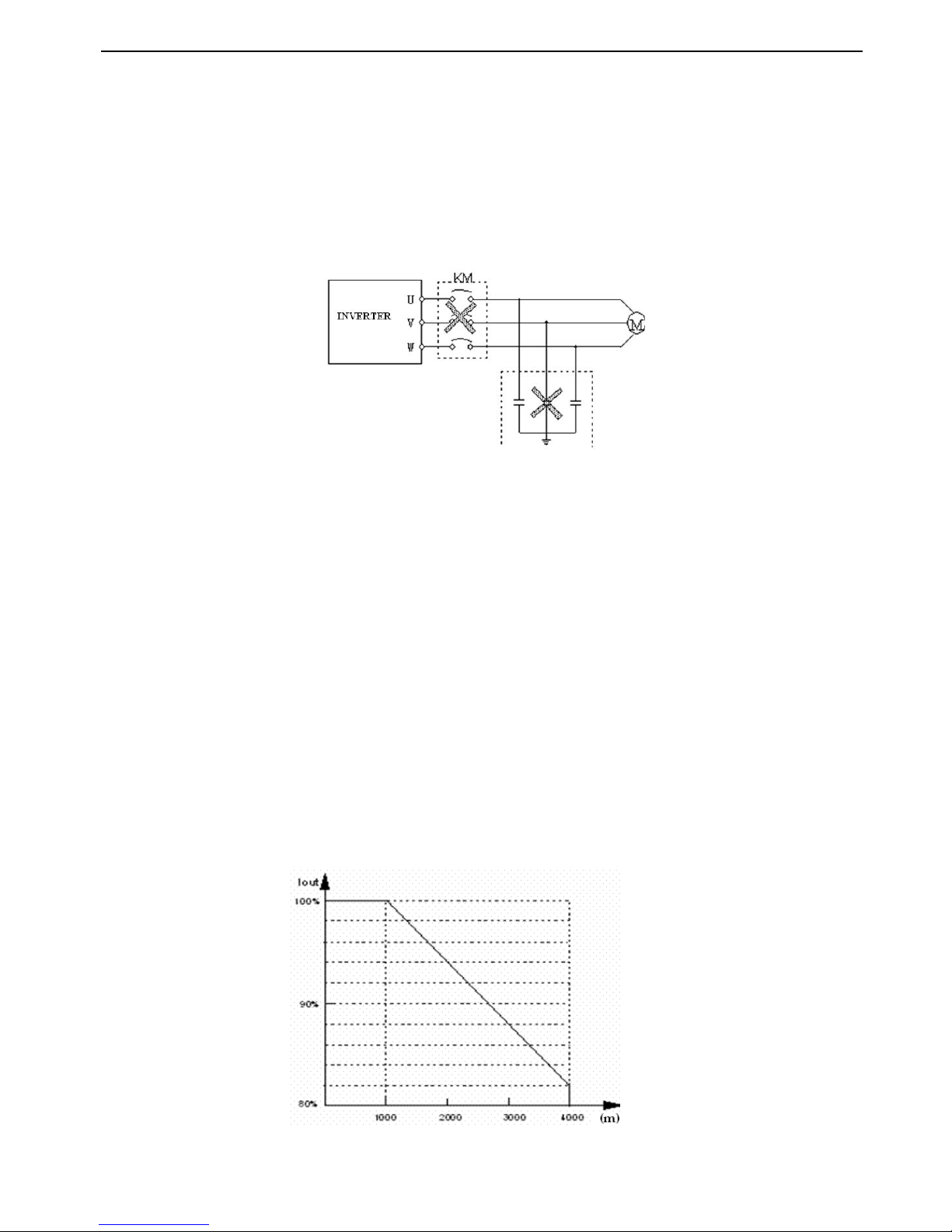
VB3/ V5 / VB 5 series inverter
4
M
M
M
M echanical
echanical
echanical
echanical resonance
resonance
resonance
resonance point
point
point
point of
of
of
of load
load
load
load
The inverter may encounter the mechanical resonance point of load within certain output frequency range. Jump
frequencies have to be set to avoid it.
Capacitor
Capacitor
Capacitor
Capacitor and
and
and
and resistor
resistor
resistor
resistor
Because the inverter output pulse wave, capacitor and resistors shouldn't be connected with the output terminals of the
inverter, or the inverter may trip or components may be damaged; Besides, don ’ t connect switch components such as air
switch and contactor with the output terminals is recommended, as shown in Fig.0-1(If switch components need to be
connected with the output terminals, make sure output current of the inverter is zero when switch is acting).
Fig.0-1
Fig.0-1
Fig.0-1
Fig.0-1 Capacitor is prohibited to be connected with
output terminals of inverter
Derat
Derat
Derat
Derat
e
e
e
e
according
according
according
according to
to
to
to basic
basic
basic
basic frequency
frequency
frequency
frequency setting
setting
setting
setting
When the basic frequency is lower than the reference frequency, please consider duration for the motor so as to avoid
motor’s damage caused
by
overheat ing
.
Running
Running
Running
Running
at
at
at
at
frequency
frequency
frequency
frequency above
above
above
above 50Hz
50Hz
50Hz
50Hz
If running at frequency above 50Hz, besides the increment of vibration and noise, the ranges of running speed of motor
shaft and mechanical device have to be guaranteed. Be sure to make an enquiry first.
The
The
The
The electro-thermal
electro-thermal
electro-thermal
electro-thermal protective
protective
protective
protective value
value
value
value of
of
of
of motor
motor
motor
motor
If the applicable motor is selected as per requirements, the inverter can perform the thermal protection to the motor. If the
ratings of applied motor are not in compliance with the inverter, be sure to adjust the protective value or adopt other
protective measures to guarantee the safe running of motor.
Altitude
Altitude
Altitude
Altitude and
and
and
and derat
derat
derat
derat e
e
e
e
When the altitude is higher than 1000m, the cooling effect of inverter is deteriorated because of the rareness of air, deration
must be considered, shown in Fig. 0-2 which indicates the relationship between the altitude and rated current of frequency
inverter.
Fig
Fig
Fig
Fig
.
.
.
. 0-2
0-2
0-2
0-2 The relationship between the altitude and rated
current of frequency inverter
Page 11

VB3/ V5 / VB 5 series inverter
5
About
About
About
About protect
protect
protect
protect ion
ion
ion
ion classes
classes
classes
classes
The protection class of V5 /F5 series inve rter IP20 is reached in the case of status display unit or keyboard.
When you scrap the inverter, please pay attention to :
Explosion risk of capacitor: The capacitors in the main circuits may explode when they are burned.
Waste gas when plastic parts are burned: Poisonous gas may be generated when front panel is burned.
Dispose method: Please dispose as industrial rubbish.
◎ Note
Note
Note
Note For
For
For
For Scrap
Scrap
Scrap
Scrap ◎
Page 12
VB3/ V5 / VB 5 series inverter
6
1
1
1
1
Product
Product
Product
Product Instruction
Instruction
Instruction
Instruction
1-1.
1-1.
1-1.
1-1. Product
Product
Product
Product o
o
o
o verview
verview
verview
verview
V5 /F5 series inverter is produced
by
Thinget Co., Ltd with high performance, easy operating and low noise. It is a
innovative product with a series advanced and pra c tical running and control functions such as practical PI, flexible input
and output terminals, parameter modification online, fixed length control, traverse operation, RS485 control , bus-mastering .
It provides OEM customers with high integrated, reliable, cost-effective solution .
VB3 only has 220V level types; V5 /VB5 series frequency inverter has 220V and 380V voltage levels. Suitable motor
capability is from 0. 4 KW to 55 KW .
Please
Please
Please
Please note
note
note
note 220V
220V
220V
220V level
level
level
level types
types
types
types have
have
have
have no
no
no
no vector
vector
vector
vector control
control
control
control
1-2.
1-2.
1-2.
1-2. Product
Product
Product
Product t
t
t
t echnical
echnical
echnical
echnical s
s
s
s pecification
pecification
pecification
pecification
1
1
1
1 .
.
.
. Technical
Technical
Technical
Technical s
s
s
s pecification
pecification
pecification
pecification
L evelType
R ated c apacity (
KVA
)
R ated output current ( A )
S uitable motor ( KW )
220V
S ingle phase
VB3-20P4
0.9
3.0
0.4
VB 3 -20P7
1.5
4.7
0.75
VB5-21P5
2.8
7.5
1.5
380V
T hree pahse
VB5-41P5
2.5
4. 5
1.5
VB5-42P2
3.0
6.0
2.2
VB5-43P7
5.9
9.6
3.7
V B 5-45P5
8.5
14.0
5.5
V B 5-47P51117.0
7.5
V5-40111525
11
V5-4015
20
3 3
15
V5-4018
253818.5
V5-4022
30
4 6
22
V5-4030
406030
V5-403 7
5 07537
V5-40 456090
45
V5-40 5575110
55
Name
Name
Name
Name Designation
Designation
Designation
Designation Rules
Rules
Rules
Rules
V
V
V
V 5
5
5
5 - 2
2
2
2 3
3
3
3
P
P
P
P
7
7
7
7
Max Suitable Motor's Capacity
0 11 : 11 KW
1P5 : 1.5KW
A nd so on
( P : Stands for radix Point )
V oltage Level
2 : 2 2 0V
4 : 380 V
Type
Type
Type
Type
Inverter Series
V5
: VVVF /vector control
VB5: VVVF /vector control
VB3: VVVF control, mini type
( B means black cover)
Page 13
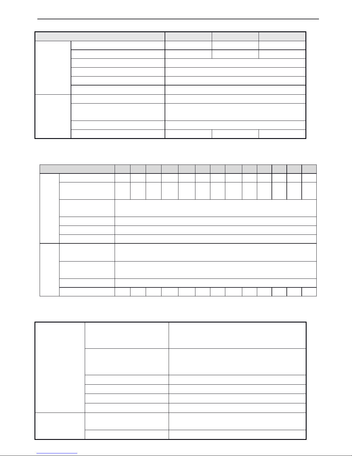
VB3/ V5 / VB 5 series inverter
7
2
2
2
2 2
2
2
2 0V
0V
0V
0V
380
380
380
380 V
V
V
V
Common
Common
Common
Common c
c
c
c haracteristics
haracteristics
haracteristics
haracteristics
Type
Type
Type
Type
VB3-20P4
VB3-20P4
VB3-20P4
VB3-20P4
VB3-20P7
VB3-20P7
VB3-20P7
VB3-20P7
VB5-21P5
VB5-21P5
VB5-21P5
VB5-21P5
Output
Match Motor(KW)
0. 4
0.75
1.5
Output Current(A)
3.0
4.7
7.5
Voltage(V)
AC 200
Frequency Range(Hz)
0~500
Frequency Resolution(Hz)
0.01
Over-loading Ability
150%Rated Current for 1 minutes,180% Rated Current for 1 secon d
Input
Rated Voltage/Frequency
Single-phase 220V , 50/60Hz
AC voltage permit fluctuate range
Voltage : -20% ~ +20 %
Voltage Unbalance Rate : <3%
Frequency fluctuate Range
Frequency : ± 5 %
Power Capacity (
KVA
)
0.9
1.5
2.8
Environment
Application environment
In-door, free from direct sunlight, dust, corrosive gas, oil mist,
steam, water drop etc.
Elevation
Lower than 1000m ( T he inverter should be derated when the
elevation is higher than 1000m )
Ambient Temperature
- 10 ℃ ~+ 40 ℃
Humidity
Less than 90%RH , No dry bulb
Vibration
Less than 5.9 m/s2( 0.6M )
Storage Temperature
- 20 ℃ ~+ 60 ℃
Structure
Protect Configuration
IP20(In the state of "state display units" or "keyboard" )
Cooling Manner
Fan cooling
V5/VB5-4_
V5/VB5-4_
V5/VB5-4_
V5/VB5-4_ _
_
_
_ _
_
_
_
1P5
1P5
1P5
1P5
2P2
2P2
2P2
2P2
3P7
3P7
3P7
3P7
5P5
5P5
5P5
5P5
7P5
7P5
7P5
7P5
011
011
011
011
015
015
015
015
018
018
018
018
022
022
022
022
030
030
030
030
037
037
037
037
045
045
045
045
055
055
055
055
output
S uitable motor (KW)
1.5
2.2
3.7
5.5
7.51115
18.522303745
55
R ated
current (A)
4.5
6.0
9.6
14.0
17.025333846607590110
R ate d
voltage ( V)
AC 380
frequency range (Hz)
0 ~ 500
frequency accuracy (Hz)
0.01
Overload Ability
150% Rated Current for 1 minute , 180% Rated Current for 1 s econd
I nput
Rated voltage
/Frequency
Three phase 380V ; 50Hz/60Hz
AC voltage fluctuate rang e
Voltage : -20% ~ +20 %
Voltage Unbalance Rate : <3%
Frequency fluctuate range
Frequency : ± 5 %
Power Capacity (
KVA
)
2.5
3.0
5.9
8.51115202530405060
75
Page 14
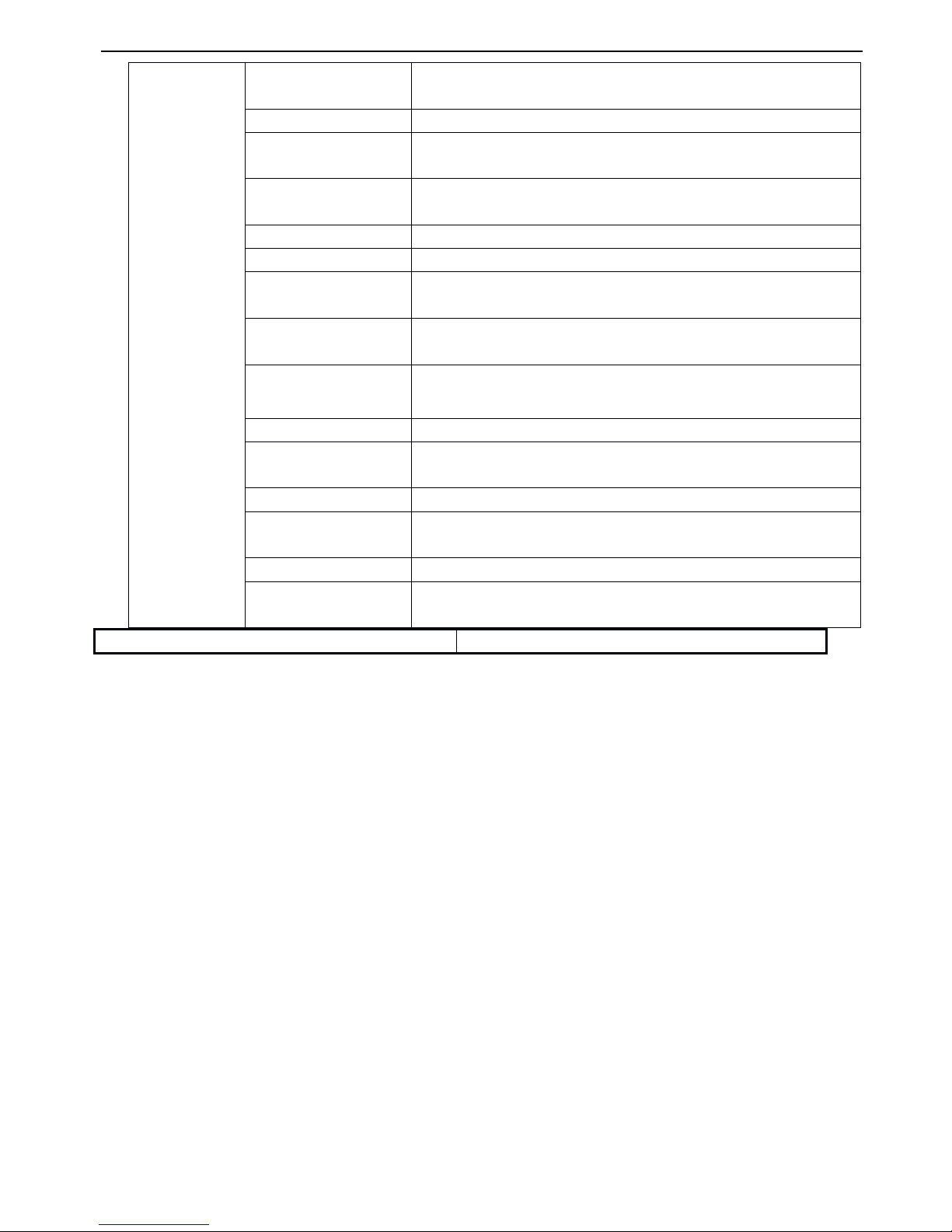
VB3/ V5 / VB 5 series inverter
8
2
2
2
2 .
.
.
. General
General
General
General Specification
Specification
Specification
Specification
Installation
Wall mounted or install inside cabinet
Main
Main
Main
Main Control
Control
Control
Control
Function
Function
Function
Function
Modulation mode
Optimized space voltage vector SVPWM modulation
Control mode
SVPWM control ( dead zone compensation for optimized low-frequency)
Frequency precision
Digital Setting: max frequency ×± 0. 01% ;
Analog Set ting : max frequency ×± 0.2%
Frequency resolution
Digital Setting : 0.01Hz ;
Analog Set ting : max frequency × 0.1%
Start frequency
0.40Hz ~ 20.00Hz
Torque boost
Auto torque boost , manual torque boost 0.1% ~ 30.0%
V/F curve
Five modes : constant torque V/F curve, 1 V/F curve mode by user and 3 kinds of
torque-derating modes ( 2 nd power , 1.7 th power , 1.2 nd power )
Acc elerate /Dec elerate curve
Two
modes : linear Acc/Dec, S curve Acc/Dec ; seven kinds of Acc/Dec time
(Maximum:6000 minutes) and unit(minute or second) is selectable.
DC braking
Initial frequency of DC braking : 0 ~ 15.00Hz
Braking time : 0 ~ 60.0 s
Braking current : 0 ~ 80 %
P ower consumption braking
P ower consumption unit inside, can be connected with external braking resistor
Jog
Range of jog frequendy : 0.1Hz ~ 50.00Hz, Acc/Dec time of jog operation 0.1 ~
60.0s
Internal PI
Be abletoform close loop control system easily
Multi-step
speed running
Multi-step speed running can be realized by internal PLC or control terminals
T
extile w obble frequency
A djustable preset frequency and center frequency
Auto voltage regulation
(AVR)
When the power system voltage changes, maintain the constant of output voltage
Page 15
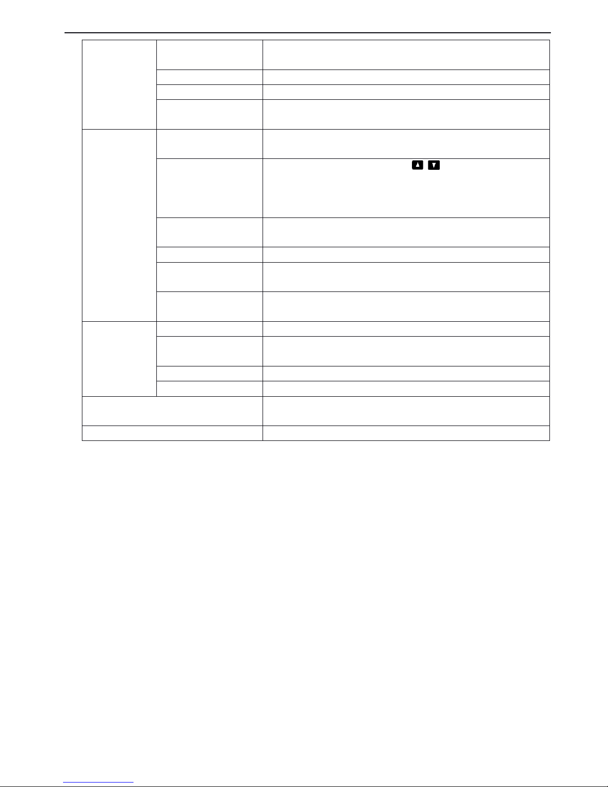
VB3/ V5 / VB 5 series inverter
9
1-3
1-3
1-3
1-3 .
.
.
. Product
Product
Product
Product a
a
a
a ppearance:
ppearance:
ppearance:
ppearance:
VB3 series 0.4~0.75KW
Auto energy saving running
V/F curve is optimiz ed automatically according
to
the load condition
to
realize
energy saving operation
Auto current limiting
running current is limited automaticallytoavoid trip caused by overcurrent
Fix-length control
T he frequency inverter will stop running when reaching the fixed length
Communication
function
W ith RS485 port, support Modbus-RTU protocol. Be with master-slave multi-
devices linkage function
Operating
Operating
Operating
Operating
function
function
function
function
R unning command channel
Operation panel set ting;control terminals set ting;serial port set ting;three mo des
are exchangeable .
F requency setting channel
Keyboard analog potentiometer set ting ; , keys set ting ; function code
digital set ting ; serial port set ting ; UP/DOW N terminal set ting ; analog voltage
set ting;analog current set ting ; pulse set ting;combination set ting ; different setti ng
modes can be select ed
D igital input channel
Forward/ Reverse running command;6 channels programmable digita l input,ca n
set 35 kinds of function , X6 support 0~20KHz pulse output
Analog input channel
2 channels analog input , 4 ~ 20mA and 0 ~ 10V can be selected
Analog output channel
1 channel analog output , 0 ~ 10V , be abletooutput setting frequency, output
frequency
Digital , pulse output
channel
1 channel programmable open-collector output ; 1 channel relay output ; 1 channel
0-20KHz pulse outpu t
Operation
Operation
Operation
Operation panel
panel
panel
panel
LED Display
Can display set ting frequency, output voltage, output current and other parameters .
External meter Display
Display output frequency, output current, output voltage and other physical
quantit ies
B utton Lock
Lock all the buttons
Parameter Copy
Function code copy among frequency inverters by remote keyboard
Protection
Protection
Protection
Protection Function
Function
Function
Function
Over current protection ; over voltage protection ; under voltage protection ; ove
r
heat protection ; over load protection
Optional
Optional
Optional
Optional parts
parts
parts
parts
Braking parts, operation panel installation seat, operation panel extension cable
Page 16
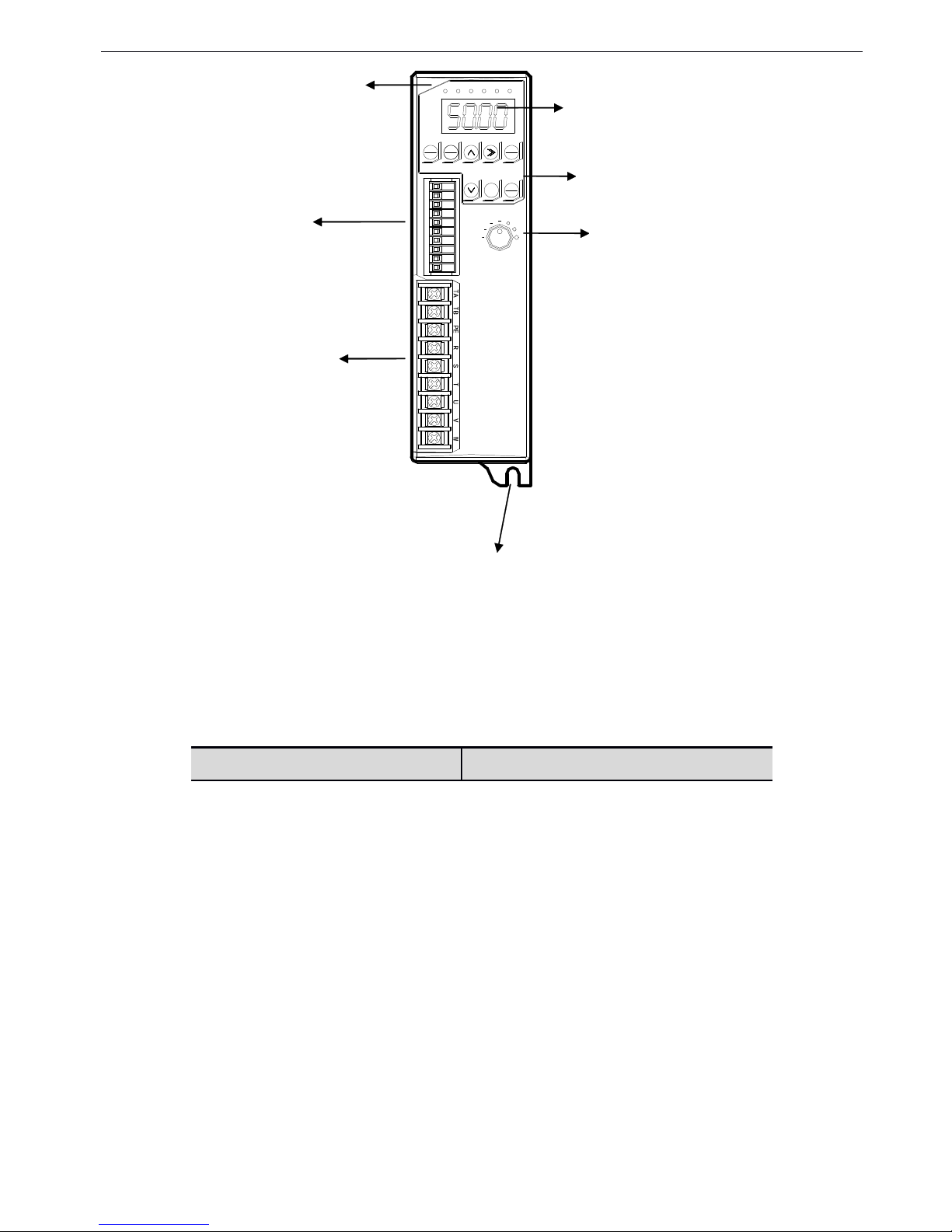
VB3/ V5 / VB 5 series inverter
10
MENU
ESC
JOG
REV
ENT
DATA
FWD
STOP
RESET
FWD REV ALM HZ V A
VB5
VB5
VB5
VB5 series
series
series
series 1.5KW~3.7KW
1.5KW~3.7KW
1.5KW~3.7KW
1.5KW~3.7KW
VB5
VB5
VB5
VB5 series
series
series
series 5.5KW~7.5KW
5.5KW~7.5KW
5.5KW~7.5KW
5.5KW~7.5KW
LED
C ontrol
terminals
P ower
terminals
M ounting hole
4 bits LED display
B uttons
A nalog potent i o meter
Page 17
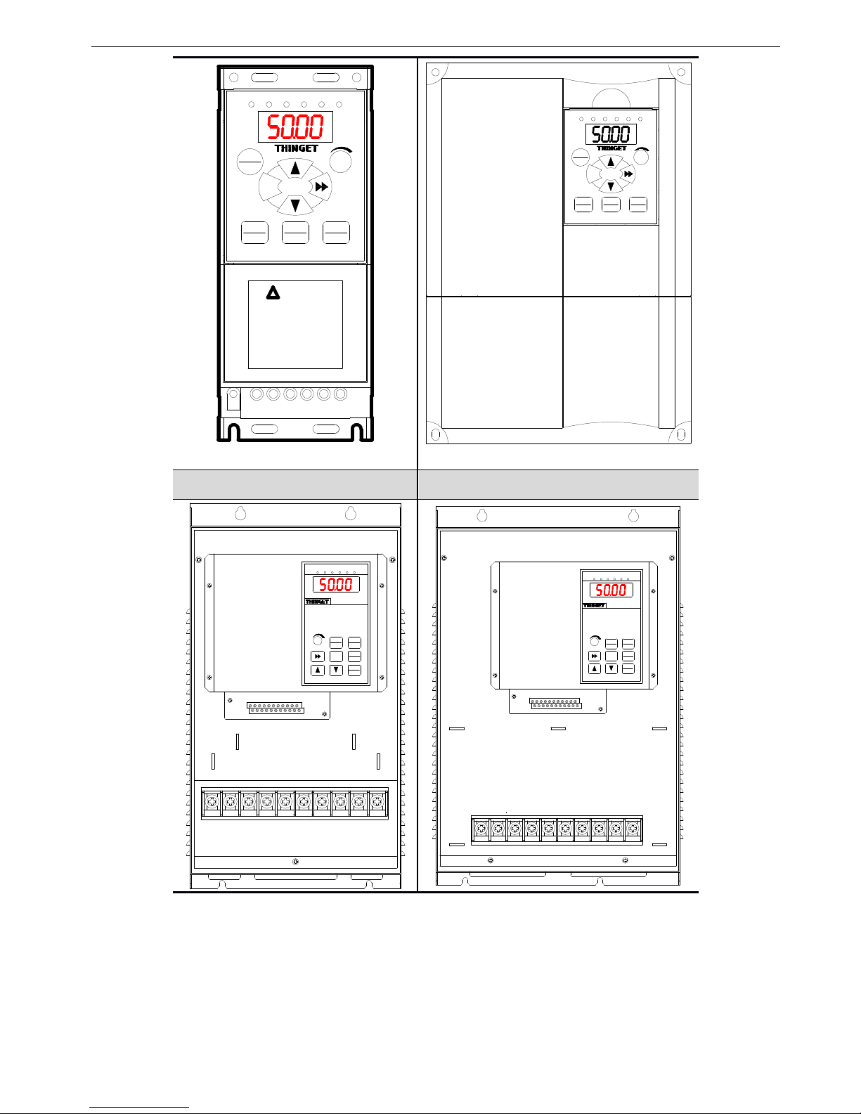
VB3/ V5 / VB 5 series inverter
11
MENU
ESC
FWD
ENT
DATA
JOG
REV
STOP
RESET
FWD REV ALM
HZ
V A
WARNING
!
* STORED CHARGE DO NOT TOUCH
UNTIL 10 MIN. AFTER DISCO-
* RISK OF ELECTRIC SHOCK-DUAL
SUPPLY DISCONNECT MAINS AND
* DO NOT CONNECT AC POWER TO
OUTPUT TERMINALS OF "U V W"
LOADSHARING BEFORE SERVICE
NNECTION
MENU
ESC
FWD
ENT
DATA
JOG
REV
STOP
RESET
FWD REV ALMHZV A
V5
V5
V5
V5 series
series
series
series 11
11
11
11 ~ 18.5KW
18.5KW
18.5KW
18.5KW
V5
V5
V5
V5 series
series
series
series 22
22
22
22 ~ 55KW
55KW
55KW
55KW
MENU
ESC
ENTER
DATA
FWD
JOG
REV
STOP
RESET
FWD REV ALM HZ V A
MENU
ESC
ENTER
DATA
FWD
JOG
REV
STOP
RESET
FWD REV ALM HZ V A
Page 18
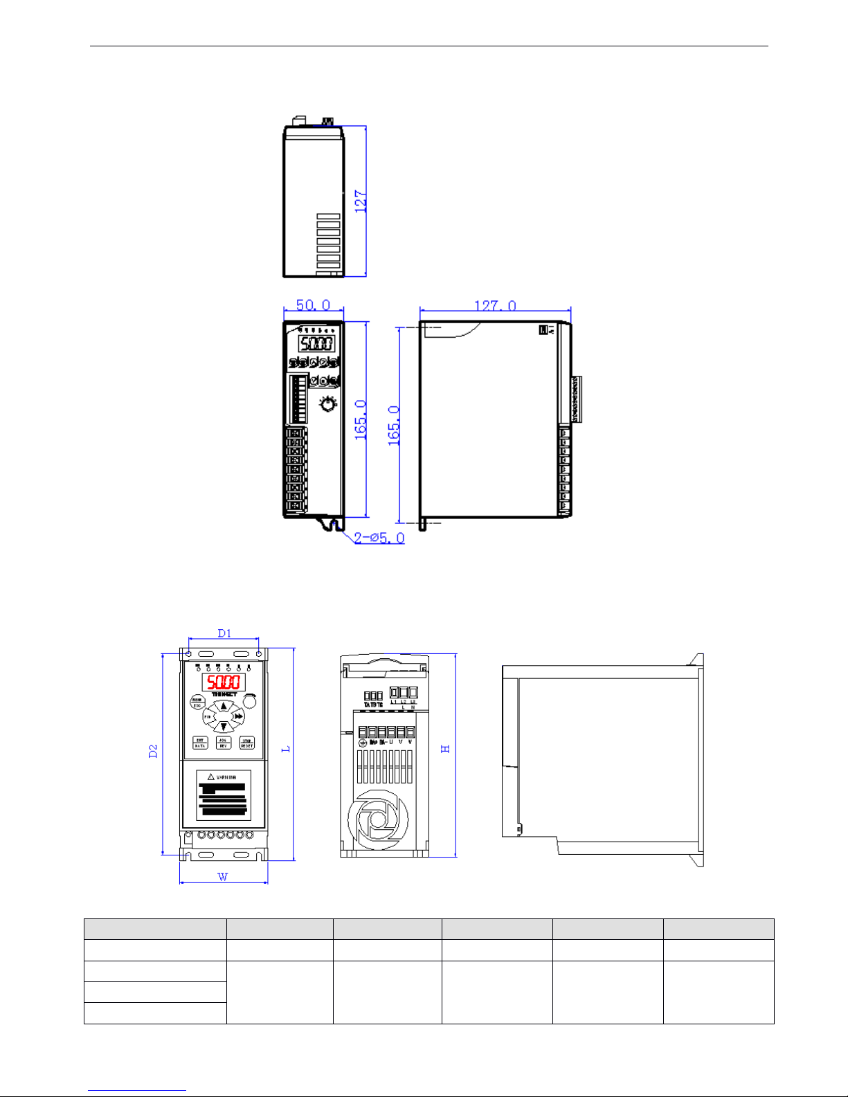
VB3/ V5 / VB 5 series inverter
12
1-4.
1-4.
1-4.
1-4. Product
Product
Product
Product d
d
d
d imension
imension
imension
imension
V
V
V
V B3
B3
B3
B3 series
series
series
series 0.
0.
0.
0. 4
4
4
4 ~ 0.75
0.75
0.75
0.75 KW
KW
KW
KW ( Unit:
Unit:
Unit:
Unit: mm
mm
mm
mm )
VB5
VB5
VB5
VB5 series
series
series
series 1.5
1.5
1.5
1.5 ~ 3.7KW
3.7KW
3.7KW
3.7KW ( Unit:
Unit:
Unit:
Unit: mm
mm
mm
mm )
The
The
The
The details
details
details
details of
of
of
of the
the
the
the dimension
dimension
dimension
dimension :
:
:
:
Type
WD1LD2H
VB5-21P57056
170
160
162
VB5-41P5
8056200
190
162
VB5-42P2
VB5-43P7
Page 19
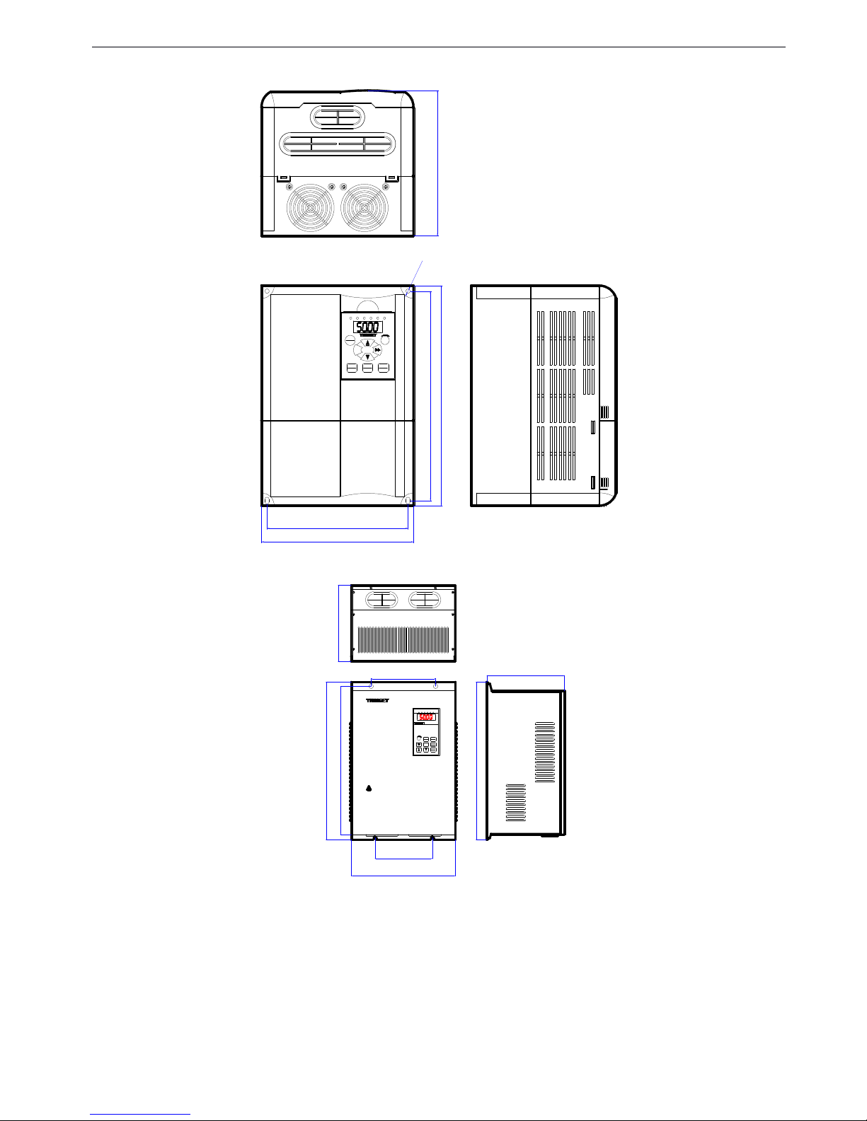
VB3/ V5 / VB 5 series inverter
13
VB5
VB5
VB5
VB5 series
series
series
series 5.5~7.5KW
5.5~7.5KW
5.5~7.5KW
5.5~7.5KW ( Unit:
Unit:
Unit:
Unit: mm
mm
mm
mm )
MENU
ESC
FWD
ENT
DATA
JOG
REV
STOP
RESET
FWD REV ALM HZ V A
180.0
167.0
260.0
247.5
171.8
?5.0
V5
V5
V5
V5 series
series
series
series 11
11
11
11 ~ 55
55
55
55 KW
KW
KW
KW ( Unit:
Unit:
Unit:
Unit: mm
mm
mm
mm )
MENU
ESC
ENTER
DATA
FWD
JOG
REV
STOP
RESET
FWD REV ALM HZ V A
L
W
D2
D3
D1
L
H
* STORED CHARGE DO NOT TOUCH UNTIL
10 MIN. AFTER DISCONNECTION
* RISK OF ELECTRIC SHOCK-DUAL SUPPLY
DISCONNECT MAINS AND LOADSHARING
WARNING
!
* DO NOT CONNECT AC POWER TO OUTPUT
TERMINALS OF "U V W"
BEFORE SERVICE
H
T
T
T
T h
h
h
h
e
e
e
e
details
details
details
details of
of
of
of the
the
the
the dimension:
dimension:
dimension:
dimension:
Page 20
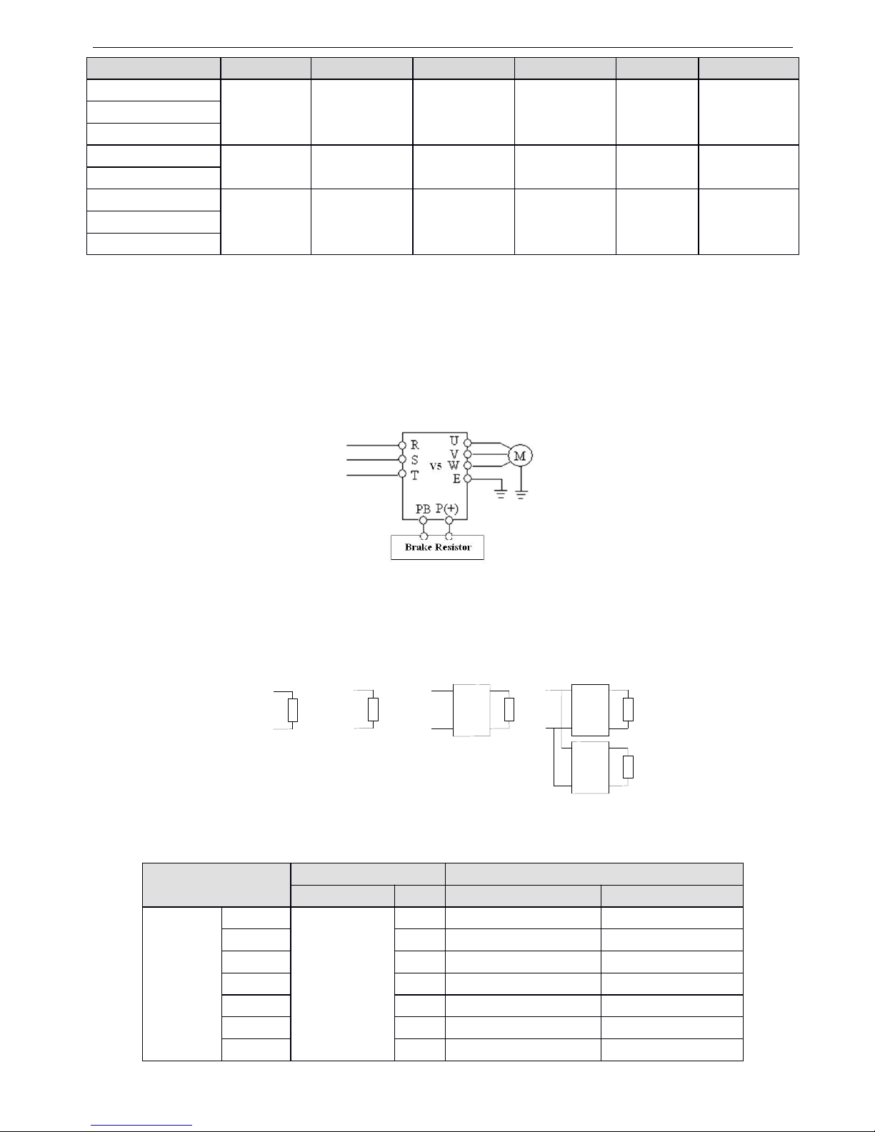
VB3/ V5 / VB 5 series inverter
14
1-5.
1-5.
1-5.
1-5. Choose
Choose
Choose
Choose f
f
f
f ittings
ittings
ittings
ittings
Brak
Brak
Brak
Brak ing
ing
ing
ing Resistor
Resistor
Resistor
Resistor
1.5 ~18.5KW series inverter s have brak ing unit inside (not include VB5-21P5)
.
If you have the requirements of power
consumption braking , choose brak ing resist or /unit according to table 1-1 , 22KW and above inverters need to connect
braking unit. T he braking resistor connection method is shown as below:
Figure
Figure
Figure
Figure 1-1
1-1
1-1
1-1 Wiring
Wiring
Wiring
Wiring of
of
of
of inverter
inverter
inverter
inverter and
and
and
and brake
brake
brake
brake units
units
units
units
E ach power level inverter is corresponding to the following connection method:
Table
Table
Table
Table
1-1
1-1
1-1
1-1 Brak
Brak
Brak
Brak ing
ing
ing
ing resistor
resistor
resistor
resistor selection
selection
selection
selection
TypeWD1LD2HD3
V5-4011
230
120
420
160
218
400
V5-4015
V5-4018
V5-4022
290
180
450
210
217
430
V5-4030
V5-4037
375
230
581
230
261
551
V5-4045
V5-4055
Spec.
Spec.
Spec.
Spec. ( KW
KW
KW
KW )
B
B
B
B raking
raking
raking
raking unit
unit
unit
unit
B
B
B
B raking
raking
raking
raking resistor
resistor
resistor
resistor
spec
spec
spec
spec
No.
No.
No.
No.
B
B
B
B raking
raking
raking
raking resistor
resistor
resistor
resistor ( Ω
Ω
Ω
Ω )
B
B
B
B raking
raking
raking
raking power
power
power
power ( W
W
W
W
)
380V
380V
380V
380V
1.5
B uilt-in
1
300
400
2.2
1
200
500
3.7
1
200
500
5.5
1
100
500
7.5
1
75
1000111
50
1000
15
1
40
1500
Page 21
VB3/ V5 / VB 5 series inverter
15
O
O
O
O per
per
per
per ate
ate
ate
ate panel
panel
panel
panel mounting
mounting
mounting
mounting seat
seat
seat
seat
O
O
O
O peration
peration
peration
peration panel
panel
panel
panel extension
extension
extension
extension cable
cable
cable
cable
The frequency inverter will be attached with 0.3m extension cable when out of factory. Besides, we also provide 0.5m, 1.0m, 1.5m
extension cable.
18.5
1
32
5000
22
BRU-4045
1
27.2
5000301
20
6000
37
1
16
9600451
13.6
9600
55
1
10
12000
O
O
O
O perate
perate
perate
perate panel
panel
panel
panel
P
P
P
P ower
ower
ower
ower (KW)
(KW)
(KW)
(KW)
S
S
S
S uitable
uitable
uitable
uitable
T
T
T
T
ype
ype
ype
ype
M
M
M
M ounting
ounting
ounting
ounting dimension
dimension
dimension
dimension ( mm
mm
mm
mm )
V5-OPU-01
1.5~7.5
VB5 series
62*75
V5-OPU-03
11~55
V5 series
71*131
C
C
C
C able
able
able
able type
type
type
type
L
L
L
L ength
ength
ength
ength (m)
(m)
(m)
(m)
V 5-ECC-05
0.5
V5-ECC-10
1.0
V5-ECC-15
1.5
Page 22
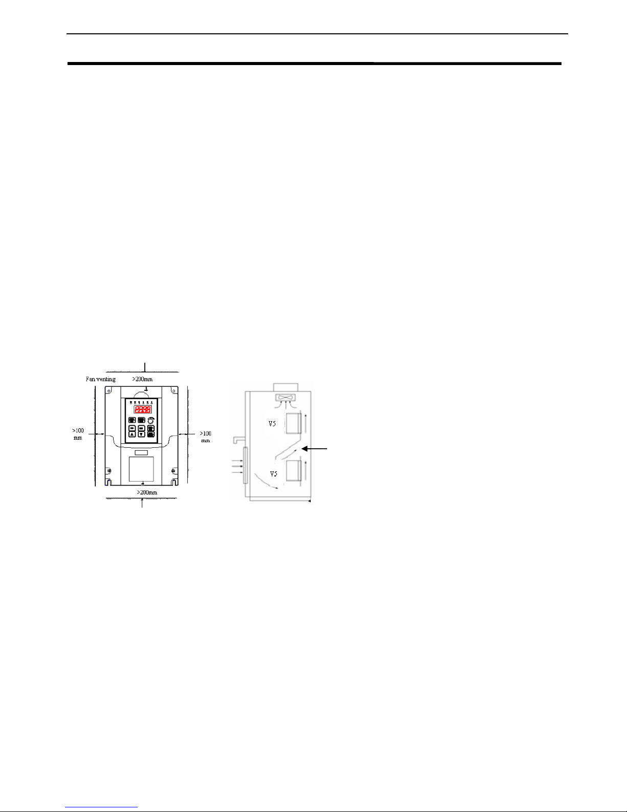
VB3/ V5 / VB 5 series inverter
16
2
2
2
2 Installation
Installation
Installation
Installation and
and
and
and W
W
W
W iring
iring
iring
iring
2-1.
2-1.
2-1.
2-1. Installation
Installation
Installation
Installation environment
environment
environment
environment
2-1-1
2-1-1
2-1-1
2-1-1 .
.
.
. Environment
Environment
Environment
Environment r
r
r
r equirement
equirement
equirement
equirement
Ambient tempeature: It is required to be within the range of -10 º C~40 º C. The inverter should be derated when the
temperature over 40 º C, at the same time ventilation and heat dissipation should be enhanced.
Far away from the location with direct sunlight, dust, floating fiber or metal powder.
Mount in the location free of corrosive gas and combustible gas.
Mount in the location free of condensing, dry bulb and the humidity should less then 95%RH.
Mount in the location where vibration less than 5.9m/s ² (0.6G)
Far away from electramagnetism interfere source and other electric instruments sensitive with electramagnetism
interfere.
2-1-2
2-1-2
2-1-2
2-1-2 .
.
.
. Mounting
Mounting
Mounting
Mounting l
l
l
l ocation
ocation
ocation
ocation and
and
and
and space
space
space
space
Mount the inverter vertically under general condition.
The mounting space and distance are shown in Fig. 2-1.
When several inverters are mounted up and down, air diver sion plate should be fixed in the middle as shown in Fig. 2-
2.
Fig.
Fig.
Fig.
Fig. 2-1
2-1
2-1
2-1 Mounting
Mounting
Mounting
Mounting Space
Space
Space
Space Fig.2-2
Fig.2-2
Fig.2-2
Fig.2-2 Mounting
Mounting
Mounting
Mounting of
of
of
of M
M
M
M ulti-
ulti-
ulti-
ulti- Inverters
Inverters
Inverters
Inverters
2-1-3
2-1-3
2-1-3
2-1-3
.
.
.
.
Mounting
Mounting
Mounting
Mounting and
and
and
and r
r
r
r emoving
emoving
emoving
emoving
Removing: Romove the four screws on the cover with phillips screwdriver
Mounting: Allign the mounting holes and then fix the screws .
Air diverting
plate
Page 23

VB3/ V5 / VB 5 series inverter
17
2-2.
2-2.
2-2.
2-2. Wiring
Wiring
Wiring
Wiring
Wiring after power off for at least 10 minutes, otherwise , an electronic short may occur.
Do not connect AC power to output terminals U, V and
W.
Both the inverter and the motor should be safety ground ed as there is leakage current inside the inverter.The diameter
of ground ing copper cable must be more than 3.5mm ² , ground ing resistor must be less than 10ohm.
W ithstand voltage test of the inverter has been done in the factory, user s would better not do it again.
Do not install electromagnetic contactor , absorption capacitor or other re sistance-capacitance absorption devices, as
shown in Fig 2 -3.
In order to make the input over - current protection and power off maint enance easily, the inverters should connect
power supply via braker .
T he connection cable of relay I/O circuit (X1~X6 , FWD , REV , OC , DO) should select the twisted-pair or shield cable
with diameter over 0.75 mm ².One terminal of the shield layer should be hung in the air and the other terminal should
be connected with the inverter’s grounding terminal E , the cable len g th should be less than 50m .
2-3.
2-3.
2-3.
2-3. Wiring
Wiring
Wiring
Wiring of
of
of
of m
m
m
m ain
ain
ain
ain circui
circui
circui
circui
t
t
t
t
terminals
terminals
terminals
terminals
2-3-1.
2-3-1.
2-3-1.
2-3-1. Wiring
Wiring
Wiring
Wiring d
d
d
d iagram
iagram
iagram
iagram
Fig.
Fig.
Fig.
Fig. 2-3
2-3
2-3
2-3 Wiring
Wiring
Wiring
Wiring of
of
of
of main
main
main
main circuit
circuit
circuit
circuit
2-3-2
2-3-2
2-3-2
2-3-2
.
.
.
.
Terminal
Terminal
Terminal
Terminal assignment
assignment
assignment
assignment and
and
and
and d
d
d
d escription
escription
escription
escription
Caution
Caution
Caution
Caution
Danger
Danger
Danger
Danger
Before layout operation, m ake sure the power supply of inverter is cut off , all the LED on the operate panel is black out
and delay for more than 10 minutes .
Wiring work can be performed after the voltage between internal electrolesis capacity “ + ” and “ – ” is below DC36V .
Wiring work can only be done by trained and professional personnel.
Before power on, please check if the power supply voltage is consistent with the inverter voltage level, otherwise
device damage , human injur ies and deaths may occur.
Page 24
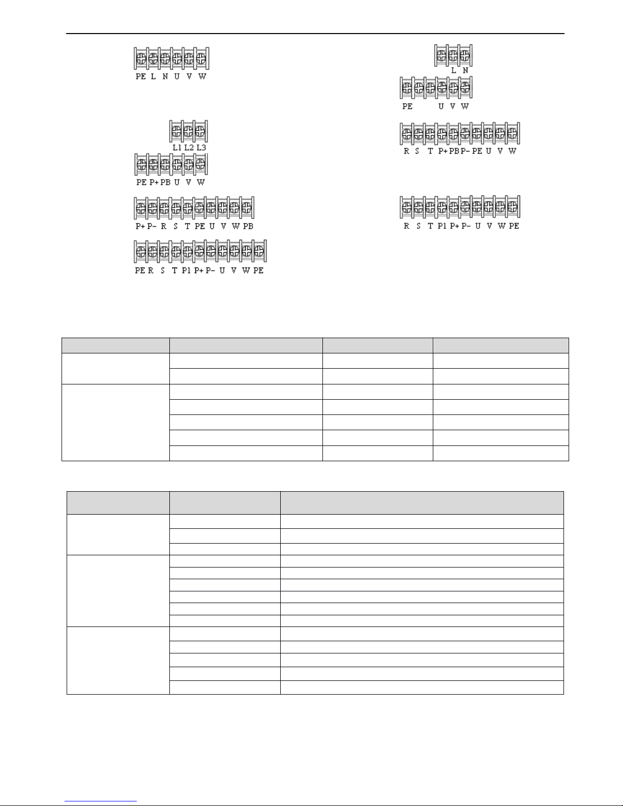
VB3/ V5 / VB 5 series inverter
18
The relationship between m ain circuit terminals and inverter types:
M ain circuit I/O terminals are shown in table 2-1:
Table
Table
Table
Table
2-1
2-1
2-1
2-1 main
main
main
main circuit
circuit
circuit
circuit I/O
I/O
I/O
I/O terminals
terminals
terminals
terminals
Fig. A
Fig. B
Fig. C
Fig. D
Fig. E
Fig. F
Fig. G
V
oltage level
Power (KW)
FigureType
220V
0.4 ~ 0.75
Fig. A
VB3
1.5
Fig. B
VB5
380V
1.5 ~ 3.7
Fig. C
VB5
5.5 ~ 7.5
Fig. D
VB5
11 ~ 18.5
Fig. E
V5
22 ~ 30
Fig. F
V5
37 ~ 55
Fig. G
V5
V
oltage
T
erminal
F unction
VB3 、 VB5 series
S ingle phase 220V
L 、 N
S ingle phase AC 220V input
U 、 V 、 W
T hree phase AC output
PE
G rounding
VB5 series
T hree phase 380V
L1 、 L2 、 L3
T hree phase AC 380V input
R 、 S 、 T
T hree phase AC 380V input
P+ 、 PB
B raking resistor
P+ 、 P-
G eneratrix + and -
U 、 V 、 W
T hree phase AC output
PE
G rounding
V5 series
T hree phase 380V
R 、 S 、 T
T hree phase AC 380V input
U 、 V 、 W
T hree phase AC output
P+ 、 P-
G eneratrix + and -
P 1 、 PB
B raking resistor
PE
G rounding
Page 25
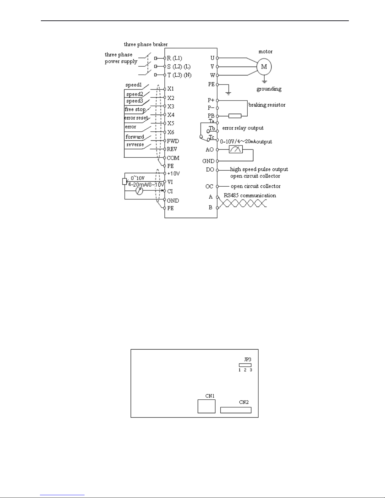
VB3/ V5 / VB 5 series inverter
19
2-4.
2-4.
2-4.
2-4. Basic
Basic
Basic
Basic r
r
r
r un
un
un
un ning
ning
ning
ning w
w
w
w iring
iring
iring
iring
Note
Note
Note
Note :
:
:
:
(1) P- terminal is only used in 5.5KW and larger inverters.
(2) L, N terminals are suitable for 220V single phase inverters.
(3) L1, L2, L3 terminals are suitable for VB5 series 1.5~3.7KW three phase types.
(4) VB5 series 1.5~3.7KW three phase has no digital input X5, analog input
Vi
and digital output DO.
(5) VB3/VB5 series single phase have no X4~X6, VI, AO, DO, OC, P+, P-, PB.
2-5.
2-5.
2-5.
2-5. Setting
Setting
Setting
Setting and
and
and
and wiring
wiring
wiring
wiring of
of
of
of control
control
control
control circuit
circuit
circuit
circuit
2-5-1
2-5-1
2-5-1
2-5-1 .
.
.
. P
P
P
P osition
osition
osition
osition and
and
and
and function
function
function
function of
of
of
of terminals
terminals
terminals
terminals and
and
and
and jumpers
jumpers
jumpers
jumpers on
on
on
on control
control
control
control panel
panel
panel
panel
0.4 ~0.75KW VB3 series inverter jumper position
Fig
Fig
Fig
Fig 2
2
2
2 - 4
4
4
4 ( a
a
a
a ) control
control
control
control panel
panel
panel
panel jumper
jumper
jumper
jumper position
position
position
position
1.5KW VB5 series single phase inverter jumper position
Page 26
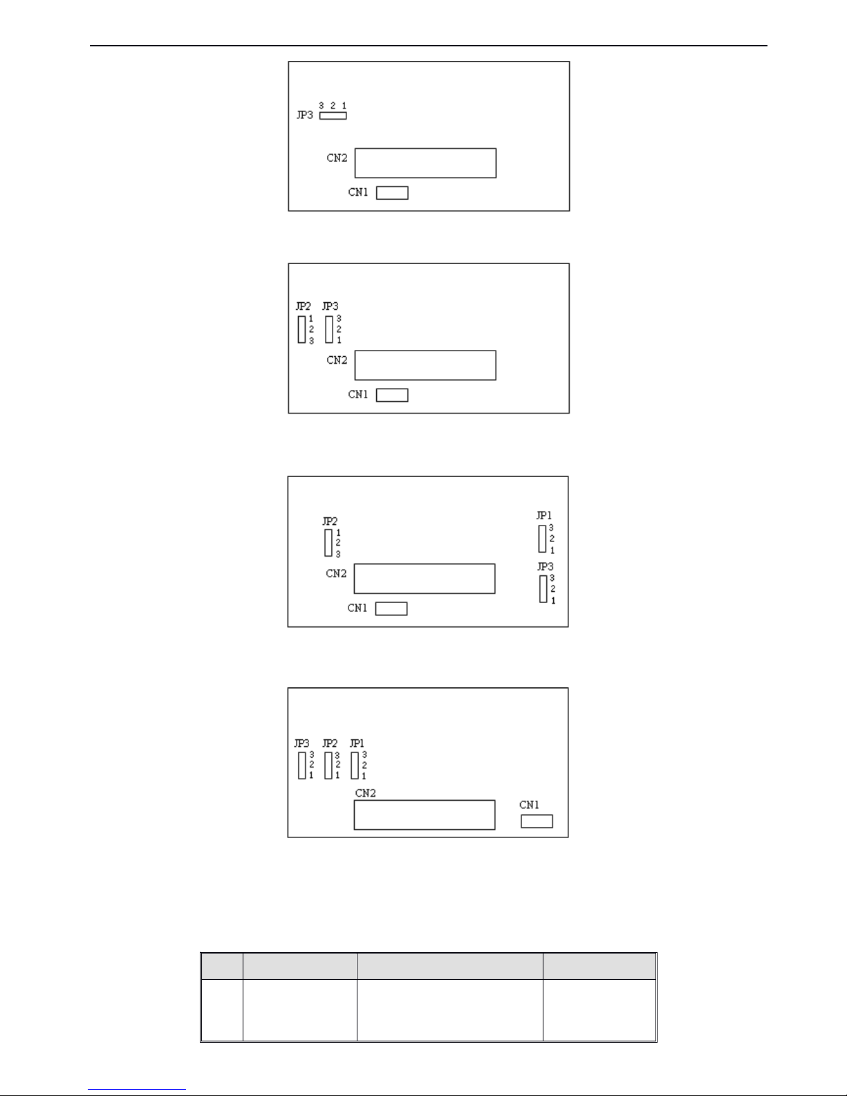
VB3/ V5 / VB 5 series inverter
20
Fig
Fig
Fig
Fig 2
2
2
2 - 4
4
4
4 ( b
b
b
b ) control
control
control
control panel
panel
panel
panel jumper
jumper
jumper
jumper position
position
position
position
1.5~3.7KW VB5 series three phase inverter jumper position
Fig
Fig
Fig
Fig 2
2
2
2 - 4
4
4
4 ( c
c
c
c ) control
control
control
control panel
panel
panel
panel jumper
jumper
jumper
jumper position
position
position
position
5.5~7.5KW VB5 series three phase inverter jumper position
Fig
Fig
Fig
Fig 2
2
2
2 - 4
4
4
4 ( d
d
d
d ) control
control
control
control panel
panel
panel
panel jumper
jumper
jumper
jumper position
position
position
position
11~55KW V5 series inverter jumper position
Fig
Fig
Fig
Fig 2
2
2
2 - 4
4
4
4 ( e
e
e
e ) control
control
control
control panel
panel
panel
panel jumper
jumper
jumper
jumper position
position
position
position
The position of terminals and jumpers on control panel are shown
in Fig. 2-4,
the function descriptions of terminals are shown
in
Table
2-3 and the function descriptions of jumpersand their set ting method are shown
in
Table2-2.
Before running the
inverter,
make sure terminals wiring and jumpers setting have been done,more than 1mm2cables are recommended to use.
Table
Table
Table
Table
2-2
2-2
2-2
2-2 Function
Function
Function
Function of
of
of
of jumpers
jumpers
jumpers
jumpers
Jumper
Function
Setup
Default Setup
JP1
Pulse output terminal
DO power selection
1 - 2 connect:External power suppl y
2 - 3 connect : Inverter’s internal
24V power supply
External power supply
Page 27
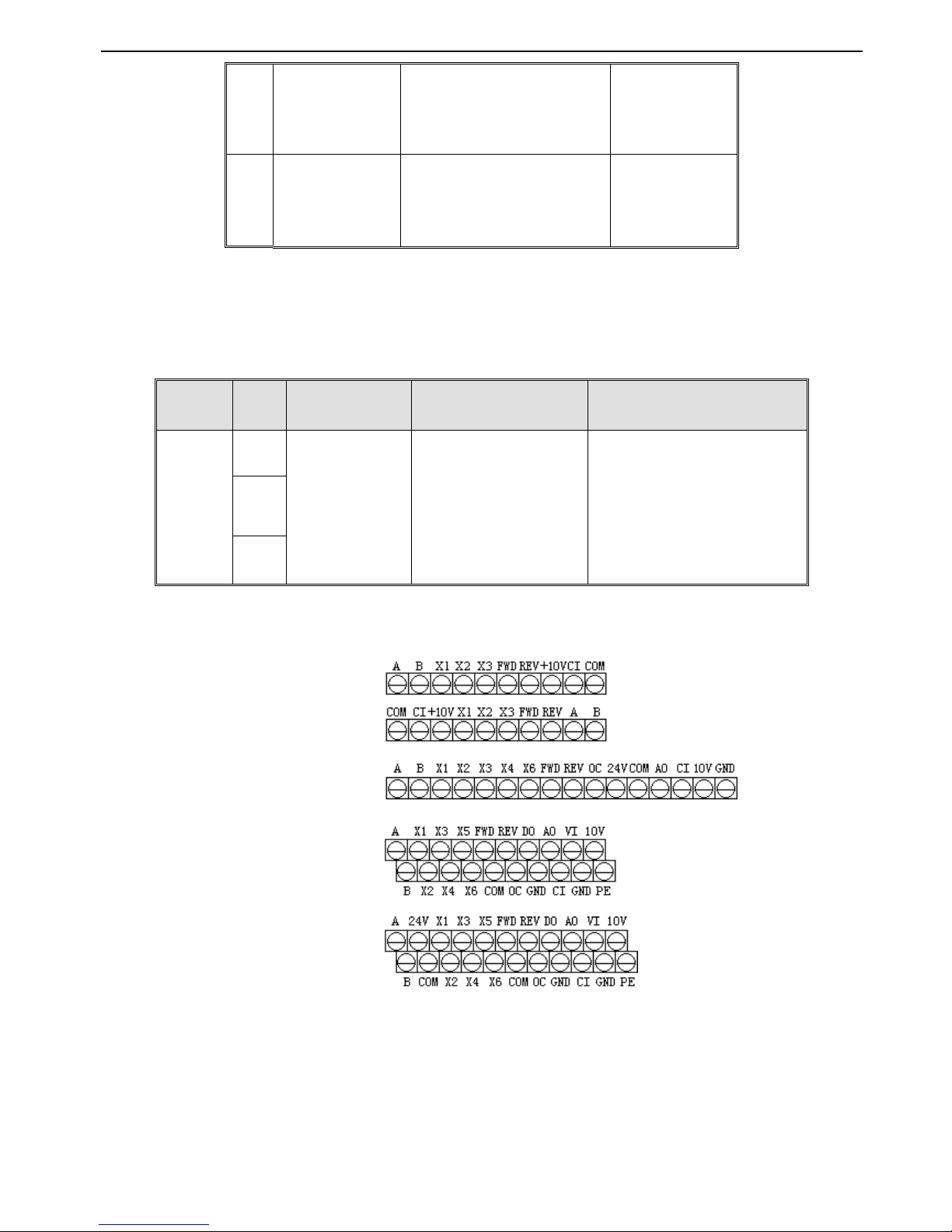
VB3/ V5 / VB 5 series inverter
21
2-5-2
2-5-2
2-5-2
2-5-2 .
.
.
. Description
Description
Description
Description of
of
of
of terminals
terminals
terminals
terminals on
on
on
on control
control
control
control panel
panel
panel
panel
1. Functions of CN1 terminal are shown as below in T able 2-3 :
Table
Table
Table
Table
2-3
2-3
2-3
2-3 Function
Function
Function
Function of
of
of
of CN1
CN1
CN1
CN1 on
on
on
on control
control
control
control panel
panel
panel
panel
2. Control circuit terminals CN2
Fig.
Fig.
Fig.
Fig. 2
2
2
2 -
-
-
- 5
5
5
5 Terminals
Terminals
Terminals
Terminals on
on
on
on control
control
control
control panel
panel
panel
panel
JP2
An a log output
terminal AO output
1 - 2 connect : 4~20mA , AO
terminal output s current signal
2 - 3 connect : 0~10V , AO terminal
output s voltage signal
0~10V
JP3
CI current/voltage
input modes selection
1-2 connect:V
side:0~10V
volta
ge
signal
2 - 3 connect : I side : 4~20mA
current signal
4~20mA
Type
Termina
l Mark
Name
Function Description
Specification
Relay output
terminal
TA
Inverter
Multi - function
relay output terminals
Inverter
Multifunctional relay output
terminals.
Please
refer to
terminal function parameters
P4.11
and description of output
terminals
TA-TC:
normal close,
TA-TB:
normal open
Contact Capacity :
AC250V/2A (COS Φ =1)
AC250V/1A (COS Φ =0.4)
DC30V/1A
TB
TC
VB3 series single phase 0.4 ~ 0.75KW
VB5 series single phase 1.5KW
VB5 series three phase 1.5 ~ 3.7KW
VB5 series three phase 5.5 ~ 7.5KW
V5 series 11 ~ 55KW
Page 28
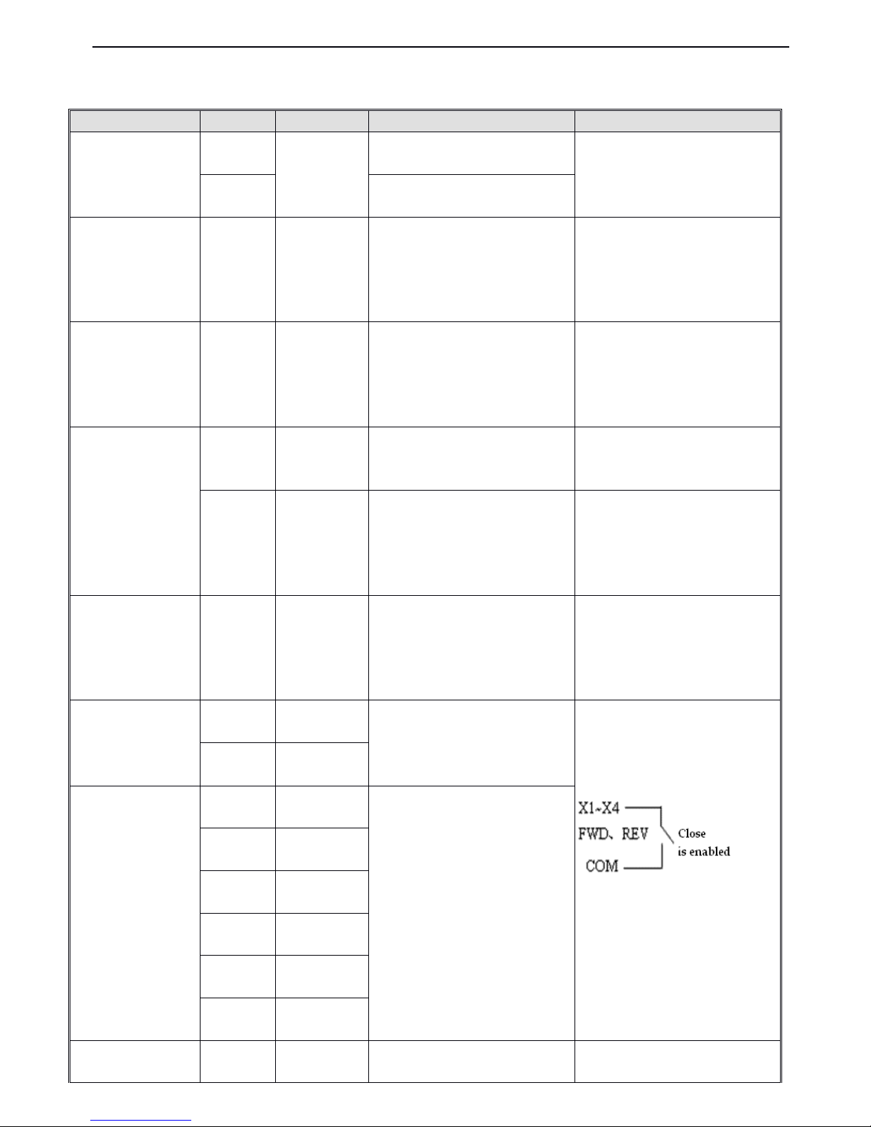
VB3/ V5 / VB 5 series inverter
22
3. CN2 terminals’function description are show n as below :
Table
Table
Table
Table
2-4
2-4
2-4
2-4 CN2
CN2
CN2
CN2 terminals
terminals
terminals
terminals
’
’
’
’
function
function
function
function description
description
description
description
Type
Terminal
Name
Terminal Function Description
Specification
C ommunication
A
RS485 port
P ositive terminal of RS485
differential signal
standard RS485 port, please use
twisted cable or shielded cable
B
N egative terminal of RS485
differential signal
Multifunction output
terminal
OC
Open collector
output terminal
1
Multi-function digital output
terminal, Refer to output terminals
’
function description of terminal
function parameters
P4.10
for
details.
(common terminals : COM)
optical coupling isolation output
voltage range:9~30V
max output current:50mA
usage
please refertoP4.10
Pulse output terminal
DO
Open collector
pulse output
terminal
Multi-function digital output terminal ,
Refer to output terminals’function
description of terminal function
parameters
P4.20,P4.21
for
details
(common terminals : COM)
Output frequency range : Decided
by function code
P4.21
, highest
20KHz
Analog input
VI
Analog input
VI
analog voltage input
(reference ground : GND)
Input voltage range : 0~10V (input
resistance : 47K Ω )
accuracy : 1/1000
CI
Analog input
CI
Analog current/voltage input ,
voltage and current are selected by
jumper JP3 and the default is
current.
(reference ground : GND)
Input voltage range : 0~10V (input
resistance : 47K Ω )
Input current range
:
4~20mA (inp ut
resistance : 500 Ω )
accuracy : 1/1000
Analog output
AO
Analog output
AO
Analog voltage/current ouput ,
They are selected by jumper JP2
and the default is voltage which can
indicate 7 values. (reference
ground : GND)
V oltage output range : 0~10V
Current output range : 4~ 20 mA
Running control
terminal
FWD
Forward
running
Forware/reverse digital command.
Refer to P4.08 for details
( instruction about 2-wire and 3-
wire control function) .
Optical coupling isolation input
Input resistance: R=2K Ω
Highest input frequency:200Hz
Input voltage range: 9 ~ 30V
REV
Reverse
running
Multifunction input
terminal
X1
Multifunction
input
1
Multi-function digital input
terminals, refer to input terminals
’
function description in terminals
’
function parameters P4.
(common terminal : COM)
X2
Multifunction
input
2
X3
Multifunction
input
3
X4
Multifunction
input
4
X5
Multifunction
input
5
X6
Multifunction
input
6
Power supply
24V
+24V power
supply
Offer +24V power supply
(negative terminal : COM)
-
Page 29
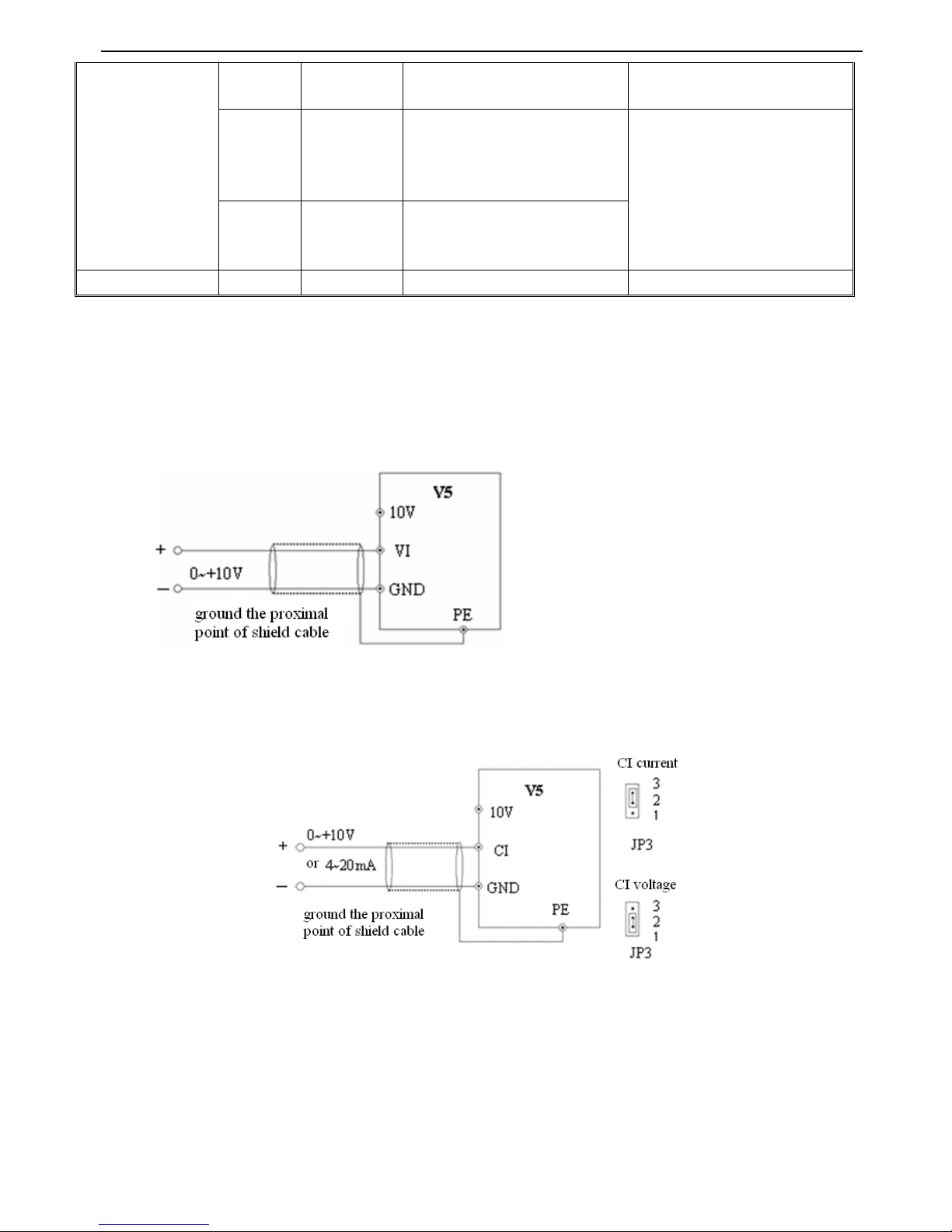
VB3/ V5 / VB 5 series inverter
23
2-5-3.
2-5-3.
2-5-3.
2-5-3. Analog
Analog
Analog
Analog input/output
input/output
input/output
input/output terminal
terminal
terminal
terminal wiring
wiring
wiring
wiring
1. VI terminal voltage signal input , wiring is shown as below :
F
F
F
F ig.
ig.
ig.
ig. 2-6
2-6
2-6
2-6 VI
VI
VI
VI terminal
terminal
terminal
terminal wiring
wiring
wiring
wiring diagram
diagram
diagram
diagram
2. CI terminal analog input, jumper select voltage input (0~10V)orcurrent input (4~20mA),wiring is shown as below :
Fig.
Fig.
Fig.
Fig. 2-7
2-7
2-7
2-7 CI
CI
CI
CI terminals
terminals
terminals
terminals
’
’
’
’
wiring
wiring
wiring
wiring
3. Wiring for a nalog ouput terminal AO
Analog output terminal AO can display various physical quantities w hen connecting external analog meter, output voltage
0~10V,
output current 4~20mA, wiring is shown in Fig.2-8 .
10V
+10V power
supply
Offer +10V power supply
(negative terminal : GND)
M ax output current:50mA
GND
+10V
power supply
common
terminal
Reference
ground of
analog signal
and +10V power
supply
COM is isolated with GND inside
inverter
COM
+24V power
supply common
terminal
Digital signal I /O common termina l
S hield
PE
S hield terminal
Page 30
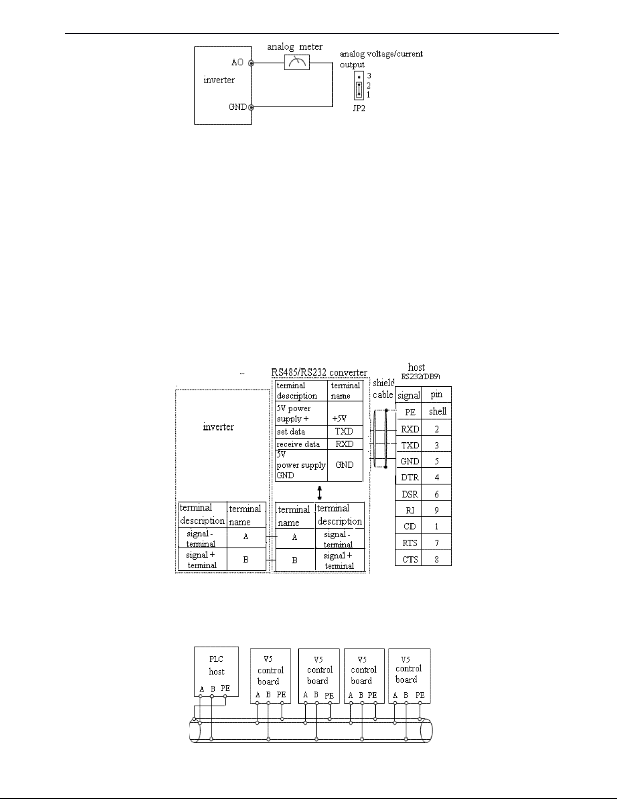
VB3/ V5 / VB 5 series inverter
24
F
F
F
F ig.
ig.
ig.
ig. 2-8
2-8
2-8
2-8 Analog
Analog
Analog
Analog output
output
output
output wiring
wiring
wiring
wiring
Note
Note
Note
Note :
:
:
:
(1) When us ing analog input, you can connect filter capaci tor or common mode inductor between VI and GND, or CI and
GND.
(2) Because analog input signal is easily interfer ed
by
outside
,
the shield cable is required,the cable length must be short
and the shield layer must be grounded well.
2-5-4
2-5-4
2-5-4
2-5-4
.
.
.
.
Connection
Connection
Connection
Connection of
of
of
of communication
communication
communication
communication terminals
terminals
terminals
terminals
The communication port of this inverter is standard RS485 port.
With the following wiring method s,you can buildup control system of one host with one slave or one host with several
slaves. Also, you can realize the functions such as real time monitor, remote control, high level automation and others for
the inveter with the host (PC or PLC) software.
Connection of inverter’s RS485 port and the host:
Fig.
Fig.
Fig.
Fig. 2-9
2-9
2-9
2-9 RS485
RS485
RS485
RS485 -
-
-
- (RS485/232)
(RS485/232)
(RS485/232)
(RS485/232) -
-
-
- RS232
RS232
RS232
RS232 cable
cable
cable
cable connection
connection
connection
connection
More than one inve r ter s can be connected through RS485 with the PLC(or PC) as the host, as shown in Fig.2-10; Also,
you can select one inveter as host and the other inverters as slaves, as shown in Fig. 2-11.Because with increasing of the
inverter’s quantities,the communication system will be interfered easier, the following wiring is recommended.
Fig.
Fig.
Fig.
Fig. 2-10
2-10
2-10
2-10 Connection
Connection
Connection
Connection of
of
of
of PLC
PLC
PLC
PLC and
and
and
and inverters
inverters
inverters
inverters
Page 31
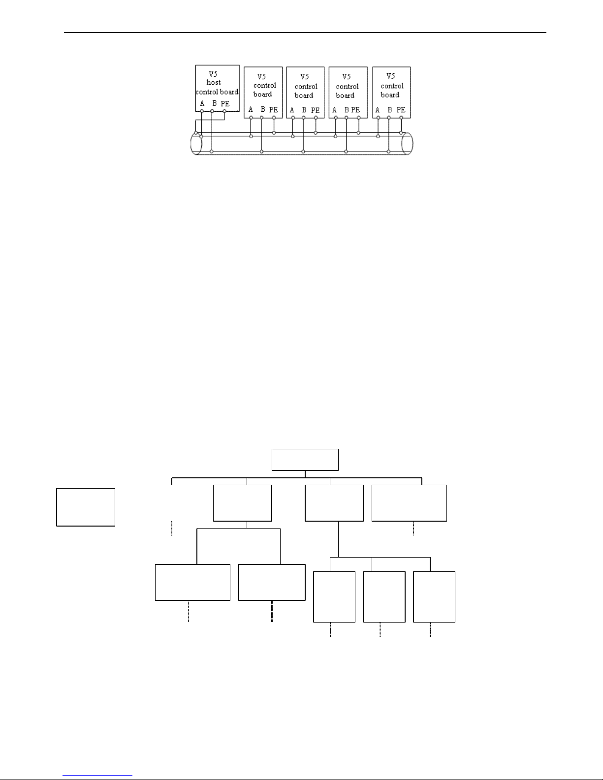
VB3/ V5 / VB 5 series inverter
25
(Inverters
(Inverters
(Inverters
(Inverters and
and
and
and motors
motors
motors
motors are
are
are
are all
all
all
all grounded
grounded
grounded
grounded well
well
well
well )
)
)
)
Fig.
Fig.
Fig.
Fig. 2-11
2-11
2-11
2-11 Connection
Connection
Connection
Connection of
of
of
of several
several
several
several inverters
inverters
inverters
inverters
(Inverters
(Inverters
(Inverters
(Inverters and
and
and
and motors
motors
motors
motors are
are
are
are all
all
all
all grounded
grounded
grounded
grounded well
well
well
well )
)
)
)
If the communication is still failed with the above connection methods
,
you can adopt the following measures:
(1) Use separate power supply for PLC or isolate the power supply .
(2) Use magnetism ring for the cable and reduce the inverter’s carrier frequency .
2-6.
2-6.
2-6.
2-6. Mounting
Mounting
Mounting
Mounting guid
guid
guid
guid
e
e
e
e
according
according
according
according with
with
with
with EMC
EMC
EMC
EMC requirement
requirement
requirement
requirement
As the inverter’s output wave is PWM, electro magnetic noise will be inevitably generated while it is working.To reduce the
inverter’s disturbance for the external devices, this chapter introduce s the mounting method in the following aspects:
control the noise, local wiring
,
grounding, leak current, usage of power supply filter.
2-6-1.
2-6-1.
2-6-1.
2-6-1. Control
Control
Control
Control the
the
the
the noise
noise
noise
noise
1. Noise type
The noise made
by
inverter
may
a ffect the neaby equipments and the effection is related to inveter’s control system,
antinoise and anti - jamming ability of the devices, wiring environment, saf e
ty
distance, grounding method and other
factors.The noise contains the following types: electrostatic induction, circuit transmit, space transmit, electro magnetic
induction and so on.
N oise types
C ircuit
transmission
S pace
transmission
E lectromagnetic
induction
L eakage current
grounding circuit
P ower supply
transmission
P ath 2
P ath 3
P ath 7, 8
M otor
cable
RF
P ower
cable
RF
I nverter
radiatio
n
P ath 4
P ath 6
2. Essential countermeasure for suppressing noise
E lectrostatic
induction
P ath 1
P ath 5
Page 32
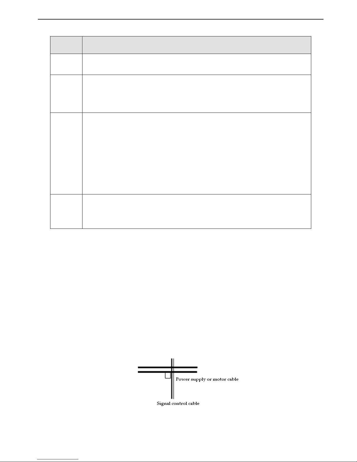
VB3/ V5 / VB 5 series inverter
26
Table
Table
Table
Table
2-5
2-5
2-5
2-5 solution
solution
solution
solution for
for
for
for control
control
control
control noise
noise
noise
noise
2-6-2.
2-6-2.
2-6-2.
2-6-2. Local
Local
Local
Local wiring
wiring
wiring
wiring and
and
and
and grounding
grounding
grounding
grounding
(1) The cable connected inverter and motor ( cables from U,V,W points ) should not p arallel with power supply calbe (R, S,
T or L, N terminal input wire ). The distance should be more than 30cm.
(2) Inverter’s output cables from U,V,W terminals is recommend to put in metal tube or slot.
(3) Control signal cables should be shield and the shield layer should be connected with inveter’s P E terminal,then ground
the point near the inverter.
(4) The gr ounding
cable
of inverter’s
P E terminal
should
be connected to ground directly.It can ’ t connect to other devices
’
grounding cables.
(5 ) Don ’ t put the signal cables in parallel with the power cables (R,S,T or L,N with U,V
,
W) or bundle these cables
together,at least 20~60 cm distance shou le be k ept ( related with power curren t ),If the signal cables and power cables
needed to be intersected, they should be vertical to each othe
r,
as shown in Fig2-12
.
Fig.
Fig.
Fig.
Fig. 2-12
2-12
2-12
2-12 Wiring
Wiring
Wiring
Wiring requirement
requirement
requirement
requirement of
of
of
of system
system
system
system
(6) The weak electricity ground ing cable such as c ontrol signal and sensor s should be separated with strong electricity
grounding cable.
Noise transmit
path
S olution
2
When the external equipment forms a loop with the inverter , the equipment may operate incorrectly caused by
leakage current of inverter grounding cable . The problem can be solved if the equipment is not grounded.
3
If the external equipment shares the same AC supply with the inverter, the inverter ’ s noise may be transmitted
along its input power supply cables, which may cause interference to other external equipment s . Take the
following actions to solve this problem: Install noise filter at the input side of the inverter , and use an isolation
transformer or power filter to prevent the noise from disturbing the external equipment.
4,5,6
(1)The equipment and the signal cables should be as far away as possible from the inverter . The signal cables
should be shielded and the shielding layer should be grounded. The signal cables should be located far away
from the input/output cables of the inverter . If the signal cables must cross over the power cables, they should be
placed at right angle to one another.
(2) Install high-frequency noise filter (ferrite common-mode choke) at the input and output of the inverter to
prevent the RF interfere of power lines.
(3) Motor cables should be placed in a tube thicker than 2mm or buried in a cement slot . Power cables should be
placed inside a metal tube and be grounded by shielding layer (Motor cable should use 4-core cable, one of the
core s should be ground ed near the inverter and another point should be connected to the motor ’ s cover ).
1,7,8
Don ’ t put the strong and weak electricity cables in parallel or bundle these cables together . Other devices should
also be away from the inverter.The devices wir e should be away from the I/O of the inverter . The signal cables
and power cables should be shielded cables. Devices with strong electric field and ma gnetic field should be away
and orthogonal from the inverter.
Page 33

VB3/ V5 / VB 5 series inverter
27
(7) Do not c onnect other devices to inverter’s power input terminals (R,S,T or L ,N).
Page 34
V5 series inverter
28
3
3
3
3 Operating
Operating
Operating
Operating Instructions
Instructions
Instructions
Instructions
3-1.
3-1.
3-1.
3-1. Run
Run
Run
Run the
the
the
the inverter
inverter
inverter
inverter
3-1-1.
3-1-1.
3-1-1.
3-1-1. Command
Command
Command
Command channel
channel
channel
channel for
for
for
for inverter
inverter
inverter
inverter running
running
running
running
We
can control the inverter’s
START,
STOP,
JOG and other running actions
by
three command channels .
1. Operation panel
Control by
,
and keys on the operation panel (default setting)
2. Control terminals
Use FWD,
REV,
COM to form 2-wire control
,
or use one terminal of X1~X6 and FWD,REV to form 3-wire control
.
3. Serial port
The operations such as
START,
STOP can be controlled
by
other devices which can communicate with the inverter.
You
can select the command channel s via parameter P 0.03 or via multi-function input terminal ( P4.00~ P4.07 function 23,
24 ).
Warning
Warning
Warning
Warning :
:
:
: The user must debug the system after changing the command channel to make sure it can meet the system
requirement, otherwise device damage and physical injury will happen.
3-1-2.
3-1-2.
3-1-2.
3-1-2. Frequenc
Frequenc
Frequenc
Frequenc y
y
y
y s
s
s
s etting
etting
etting
etting channel
channel
channel
channel
In common operating mode, there are 8 channels to set the frequency :
0 : key board analog potentiometer
1 : a a nd keys on the keyboard
2 : Operation panel function code
3 : Terminals UP/DOWN
4 : Serial port
5 : Analog VI
6 : Analog CI
7 : Pulse terminal ( PULSE )
8 : Combination
3-1-3.
3-1-3.
3-1-3.
3-1-3. Running
Running
Running
Running state
state
state
state
There are two running state: stop ping and running .
Stopping
Stopping
Stopping
Stopping state:
state:
state:
state: After the inverter is switched on and initialized, If no operating command is executed, then the inverter
enters stopping state.
Running
Running
Running
Running state
state
state
state : The inverter enters running state after it receive the running command .
3-1-4.
3-1-4.
3-1-4.
3-1-4. Running
Running
Running
Running modes
modes
modes
modes
V5 inverter has 5 kinds of running modes which can be sequenced according to the priority: Jog running → Close loop
running → PLC running → Multi-step speed running → Simple running, as shown in Fig. 3-1.
0
0
0
0 : Jog
Jog
Jog
Jog running
running
running
running
Page 35
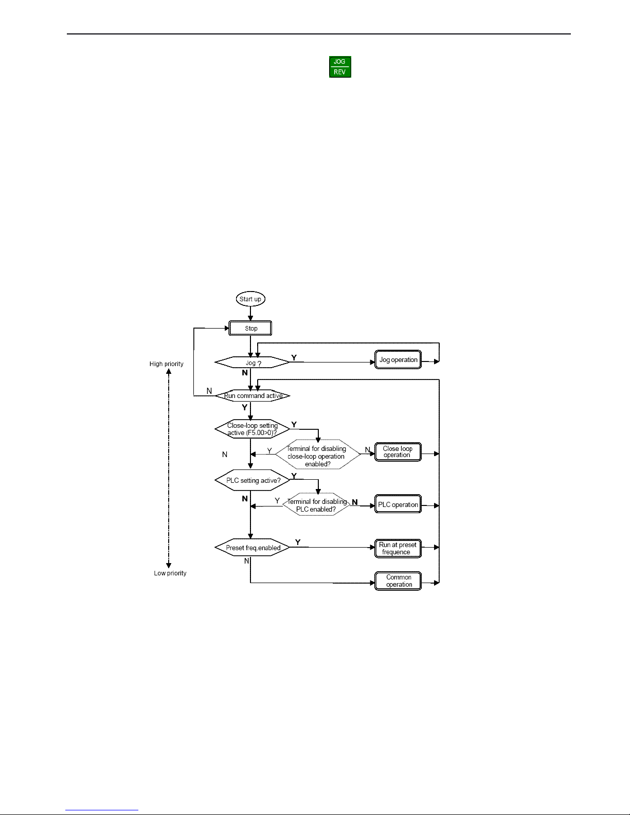
V5 series inverter
29
When the inverter is in the stopping state, it will running a c cording to jog frequency (refer to P3.06~P3.08 for details)
after receiving jog running command (e.g after pressing key)
1
1
1
1 : Close
Close
Close
Close loop
loop
loop
loop
If the close loop running function is enabled (P7.00=1), the inverter will enter the close loop running modes, that is, it
will perform PI adjust according to the reference and feedback value (refer to parameters in g roup P7),PI adjuster
ou t put is the ess en tial command of inverter’s output frequency. Close loop running can be disabled
by
multi-function
terminal (No.27 function) and the inverter will be in a running mode with low er priority.
2
2
2
2 : PLC
PLC
PLC
PLC running
running
running
running
If PLC function is enabled ( Unit’s place of P8.00 is set to a non-zero value), the inverter will enter PLC running mode
and running in the pre-defined running mode (refer to parameter description in group P8 ). PLC running can be
disabled
by
multi-function terminal (No.29 funcition) and the inverter will select a running mode with low priority.
3
3
3
3 : Multi-speed
Multi-speed
Multi-speed
Multi-speed running
running
running
running
Select Multi-frequency 1~7 (P3.26 ~ P3.32) to realize multi-speed running
by
no-zero combination of multi-function
terminal (No.1, 2 and 3 function s )
4
4
4
4 : Common
Common
Common
Common running
running
running
running
Common running is actually the open loop running mode.
Fig.
Fig.
Fig.
Fig. 3-1
3-1
3-1
3-1 Running
Running
Running
Running state
state
state
state of
of
of
of V5
V5
V5
V5
Except “ Jog running ”,other 4 kinds running modes can be enabled
by
multi-frequency setting method. Besides, “ PLC
running ”,“ multi-speed running ”,“ common running ” can be used as traverse frequency.
3-2.
3-2.
3-2.
3-2. Use
Use
Use
Use the
the
the
the keyboard
keyboard
keyboard
keyboard
3-2-1.
3-2-1.
3-2-1.
3-2-1. K
K
K
K eyboard
eyboard
eyboard
eyboard layout
layout
layout
layout
Start, speed, stop, brake, running parameter setting and control of the peripheral can be performed
by
inverter’s operation
Page 36
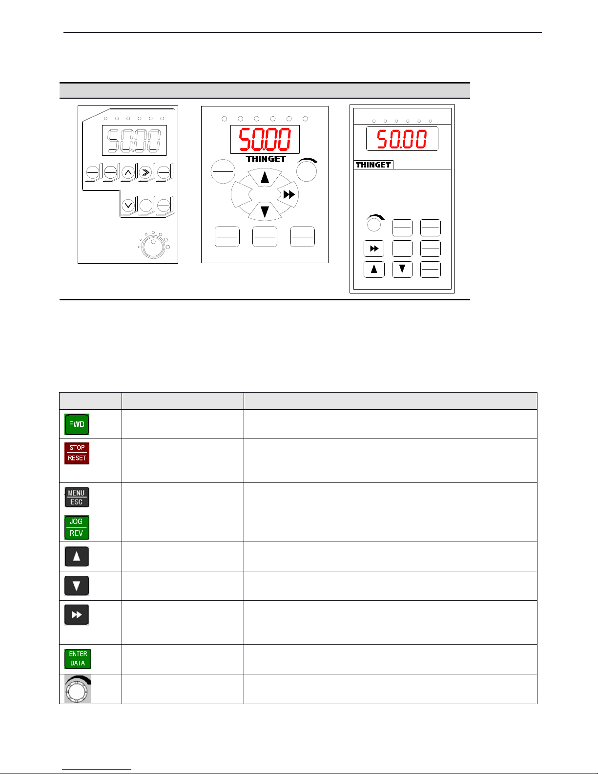
V5 series inverter
30
panel and control terminals, operation panel is shown in Fig.3-2.
Fig.
Fig.
Fig.
Fig. 3-2
3-2
3-2
3-2 Illustration
Illustration
Illustration
Illustration of
of
of
of operation
operation
operation
operation panel
panel
panel
panel
3-2-2.
3-2-2.
3-2-2.
3-2-2. Keyboard
Keyboard
Keyboard
Keyboard function
function
function
function
There are8keys and 1 analog potentiometer o n operation panel and the function
s
are shown in the following table .
VB3
VB3
VB3
VB3 0.4~0.75KW
0.4~0.75KW
0.4~0.75KW
0.4~0.75KW
VB5-OPU-01
VB5-OPU-01
VB5-OPU-01
VB5-OPU-01
V5-OPU-03
V5-OPU-03
V5-OPU-03
V5-OPU-03
MENU
ESC
JOG
REV
ENT
DATA
FWD
STOP
RESET
FWD REV ALM HZ V A
MENU
ESC
FWD
ENT
DATA
JOG
REV
STOP
RESET
FWD REV
ALM HZ V A
MENU
ESC
ENTER
DATA
FWD
JOG
REV
STOP
RESET
FWD R EV ALM H Z V A
Key
Key
Key
Key
Name
Name
Name
Name
Function
Function
Function
Function
Forward run ning
In operate panel control mode, press this key to run forward
Stop/Reset
I n operate panel control mode, press this key to stop running or return to normal
state
when inverter is in error state.
Program/Exit
Enter or exit programming state
Jog/Reverse run
P3.45=0 , jog running
P3.45=1 , reverse run ning
Increase
Increase data or function code
Decrease
Decrease data or function code
Shift
In editing state, press this key to select the bit to be changed; in other state, press this
key to see the monitor parameters.
S ave/switch
In program state, press this key to enter the next menu or saving the parameters.
Analog potentiometer
When P0.01=0, adjust
analog
potentiometer to change the inverter’s output
frequency.
Page 37
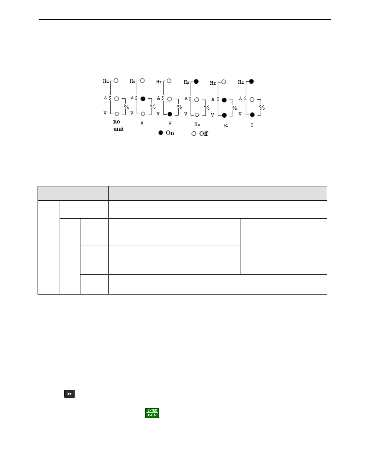
V5 series inverter
31
3-2-3.
3-2-3.
3-2-3.
3-2-3. Fucntion
Fucntion
Fucntion
Fucntion description
description
description
description of
of
of
of LED
LED
LED
LED and
and
and
and indicator
indicator
indicator
indicator
The operation panel consists of 4 bits-8segments LED,3 unit indicators and 3 state indicators. The three unit indicators
have 6 different combinations and each combination corresponds to one type of unit while settting parameters.The
relationship between the combination of the indicators and the unit are shown in Fig.3-3.
Fig.
Fig.
Fig.
Fig. 3
3
3
3 - 3
3
3
3 Unit
Unit
Unit
Unit represted
represted
represted
represted by
by
by
by combination
combination
combination
combination of
of
of
of the
the
the
the indicators
indicators
indicators
indicators
3 stat e indicators locate above the LED display on the operate panel.F rom left to right are: forward indicator FWD, reverse
indicator
REV,
alarm indicator ALM. The function s of these indicators are shown in Table3-1
Table
Table
Table
Table
3-1
3-1
3-1
3-1 Functions
Functions
Functions
Functions of
of
of
of status
status
status
status indicators
indicators
indicators
indicators
3-
3-
3-
3- 2-4
2-4
2-4
2-4
.
.
.
.
Display
Display
Display
Display of
of
of
of the
the
the
the operation
operation
operation
operation panel
panel
panel
panel
The inverter’s operation panel can display four paraters in stopping, editing, fault alarming and running.
1
1
1
1
.
.
.
.
Parameters
Parameters
Parameters
Parameters displayed
displayed
displayed
displayed in
in
in
in stopping
stopping
stopping
stopping status
status
status
status
When the inverter stops operation, operation panel displays monitor parameters in stopping status, the normally content is
setting frequency (b-01 monitor parameter). As shown in Fig.3-4,the unit indicator on the top right indicates the unit of this
parameter.
Pressing key can display other monitor parameters in stopping status circularly (the first seven monitor parameters
in B group are fault displayed value and the other monitor parameters can be defined
by
function code P3.41 and P3.42
,
please refer to Chapter 5 for details).Press in display status can shift to b-01 which can set frequency, otherwise
the panel will display the last monitor parameter constantly.
Item
Function
D isplay function
LED display
D isplay inverter’s current status parameters and setting parameters
Status indicators
FWD
F orward running indicator, inverter outputs positive phase, the
motor will run forward after connect ing to the inverter
If FWD and REV indicators all light on,
it means that the inverter are under DC
braking status
REV
Reverse running indicator , inverter output s negative phase.The
motor will run reverse after connect ing to the inverter
ALM
This indicator will light on when the inverter has fault .
Page 38
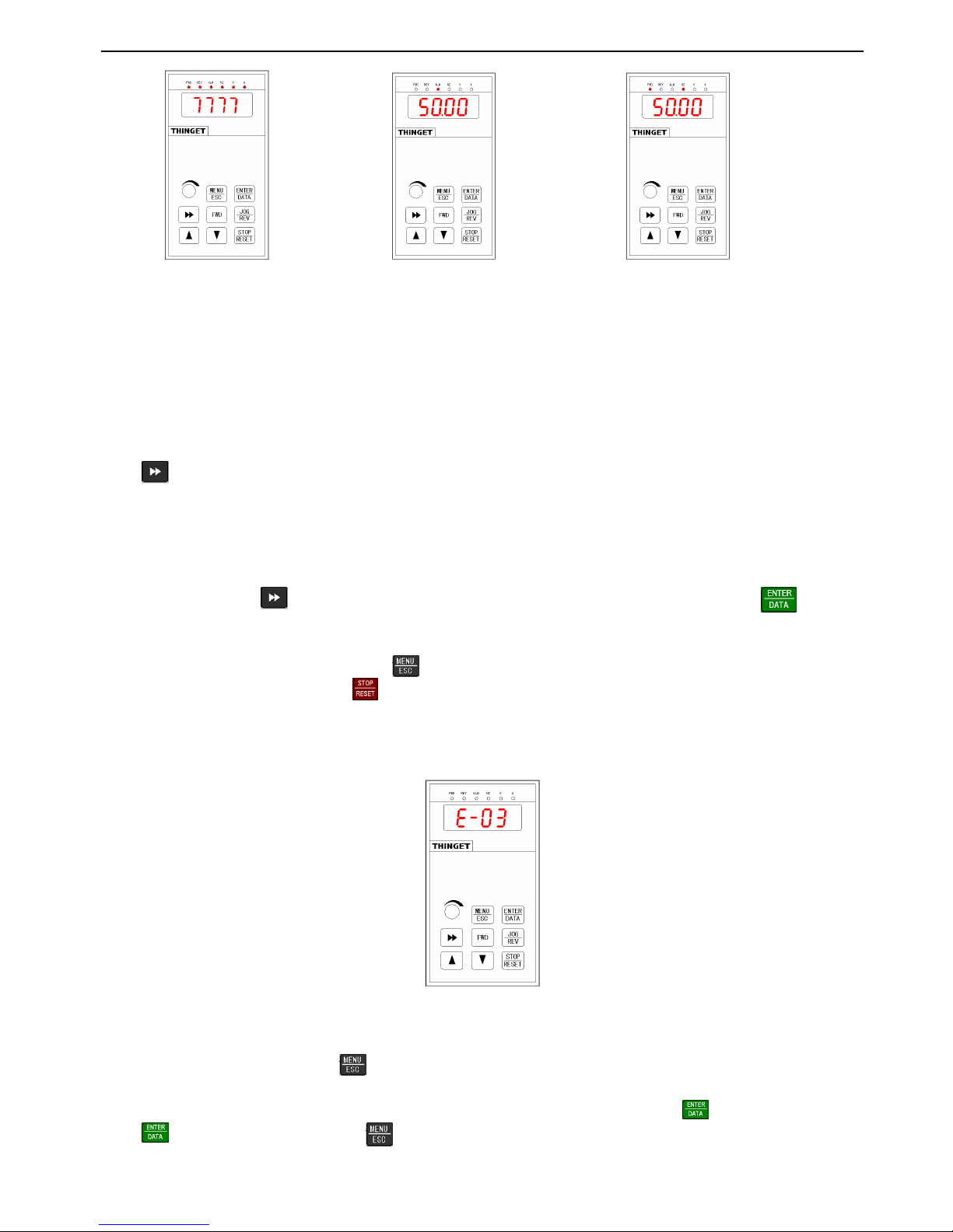
V5 series inverter
32
Fig.
Fig.
Fig.
Fig. 3
3
3
3 - 4
4
4
4 Display
Display
Display
Display during
during
during
during initialize,
initialize,
initialize,
initialize, STOP
STOP
STOP
STOP and
and
and
and RUN
RUN
RUN
RUN
2
2
2
2
.
.
.
.
Parameters
Parameters
Parameters
Parameters displayed
displayed
displayed
displayed in
in
in
in running
running
running
running status
status
status
status
When the inverter receive the running command, it starts to enter running status and operation panel will display running
monitor parameters, the default parameter is output frequency ( b-00 monitor parameter),as shown in Fig.3-4-B, the unit
indicator on the top right indicates the unit of this parameter
Press key can display parameter in running status circularly (defined
by
function code P3.41 and P3.42).While
displaying, press jkjk key to shift to the default parameter b-00 , that is output frequency , Otherwise, the operation panel
will display the last monitor parameter constantly.
3
3
3
3
.
.
.
.
Alarm
Alarm
Alarm
Alarm information
information
information
information
When then inverter detects a fault signal, the panel will display fault code, the code will flash to catch your attention as
shown in Fig.3-5; Press key to view the relative fault parameters in stopping status, and then press to shift to
fault code display.
If you want to view fault information, press to view P6 parameter in editing status.After you finding out and solve
the default, the inverter can be reset
by
key in operation panel or control terminals or communication command. The
fault code will not disappear until the fault is cleared .
Note
Note
Note
Note : For some serious default such as over current, over voltage etc. please do not reset the inverter to rerun before
confirming that the default is cleared, otherwise the inverter may be damaged.
Fig.
Fig.
Fig.
Fig. 3
3
3
3 — 5
5
5
5 Alarming
Alarming
Alarming
Alarming display
display
display
display status
status
status
status
4
4
4
4
.
.
.
.
Editing
Editing
Editing
Editing status
status
status
status
This status can be entered
by
pressing key in stopping ,running or fault alarming status(if there is a user’s password,
you should input correct password, refer to P0.00 and Fig 3-9 for details).This status can be displayed in three level menu,
they a re: code gruop → code No. → code parameter, you can enter the sub-menu
by
pressing .In code parameter status,
press to save parameter and press to exit without saving.
Fig.AFig. B
Fig. C
Power on and
initialize, display
the dynamic picture
S top status, display
the stop parameters
running status,
display the running
parameters
Page 39
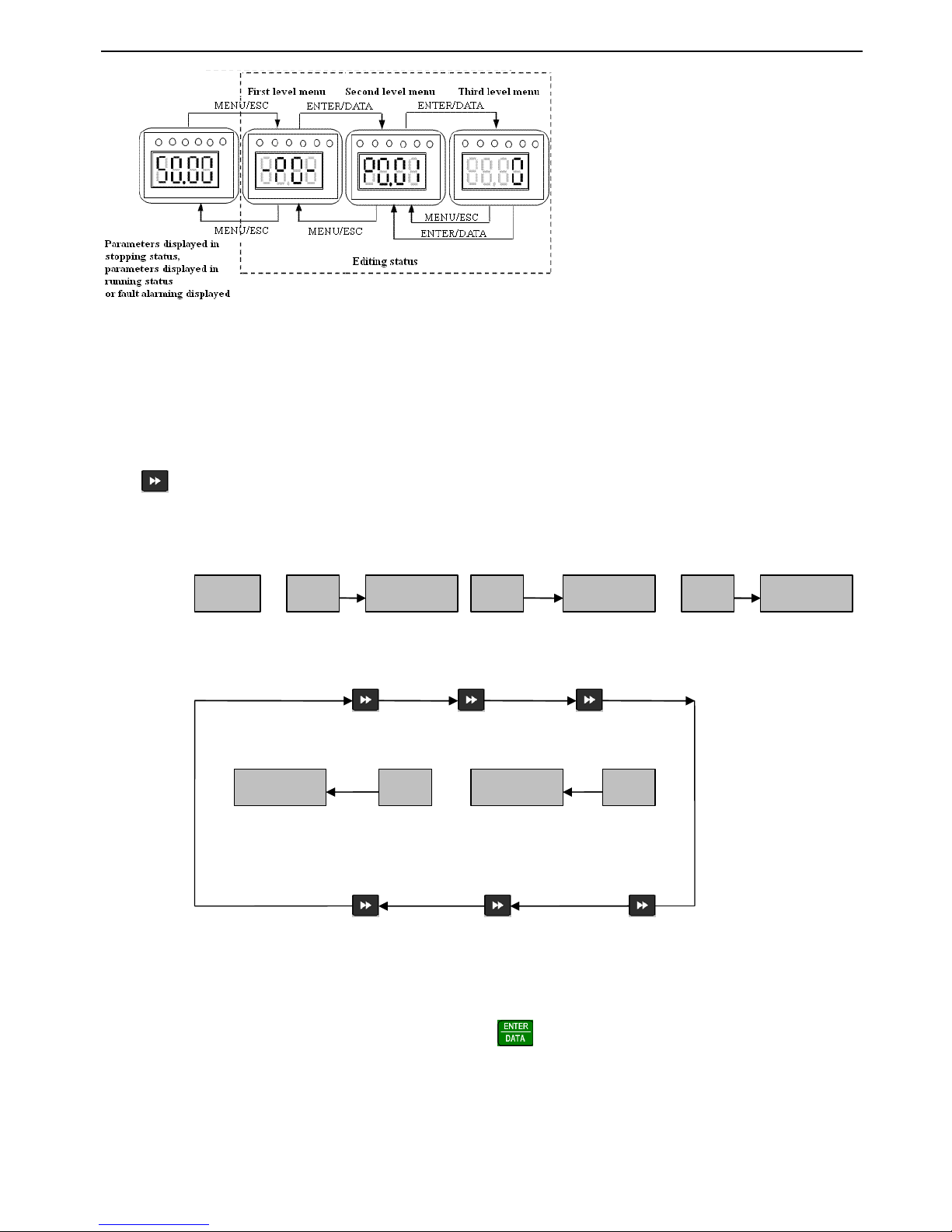
V5 series inverter
33
Fig.
Fig.
Fig.
Fig. 3
3
3
3 - 6
6
6
6 Editing
Editing
Editing
Editing status
status
status
status
3-
3-
3-
3- 2-5
2-5
2-5
2-5
.
.
.
.
Panel
Panel
Panel
Panel operation
operation
operation
operation procedure
procedure
procedure
procedure
The following shows how to do various operation
by
operation panel.
1
1
1
1
.
.
.
.
Parameter
Parameter
Parameter
Parameter Display
Display
Display
Display
Press key to display monitor parameters in b group.First display the parameter No, then shift to display parameter
value automatically in one second. The shift method is shown below in Fig 4-7
1s 1s 1s
1s 1s
Fig.
Fig.
Fig.
Fig. 3-7
3-7
3-7
3-7 Setting
Setting
Setting
Setting the
the
the
the parameters
parameters
parameters
parameters in
in
in
in running
running
running
running status
status
status
status
1) State parameter can only display seven parameters from b-00 to b-06 with factory setting, you can view other status
parameters
by
changeing P3.41 and P3.42.
(2) When you want to view status monitor parameter, press can shift to default monitor parameter display
statu s.The default monitor parameter in stopping states is setting frequency and in running states is output frequency.
2
2
2
2
.
.
.
.
Function
Function
Function
Function parameter
parameter
parameter
parameter
Take the following as an example: reset function parameter P3.06 from 5.00Hz to 8.50Hz.
LED
display
50.00
b-01
parameter
b-02
parameter
b-03
parameter
parameter
b-14
para meters
b-04
O utput frequency
B utton
operation
S et
frequency
O utput
voltage
O utput
current
G eneratrix
voltage
S et length
Page 40
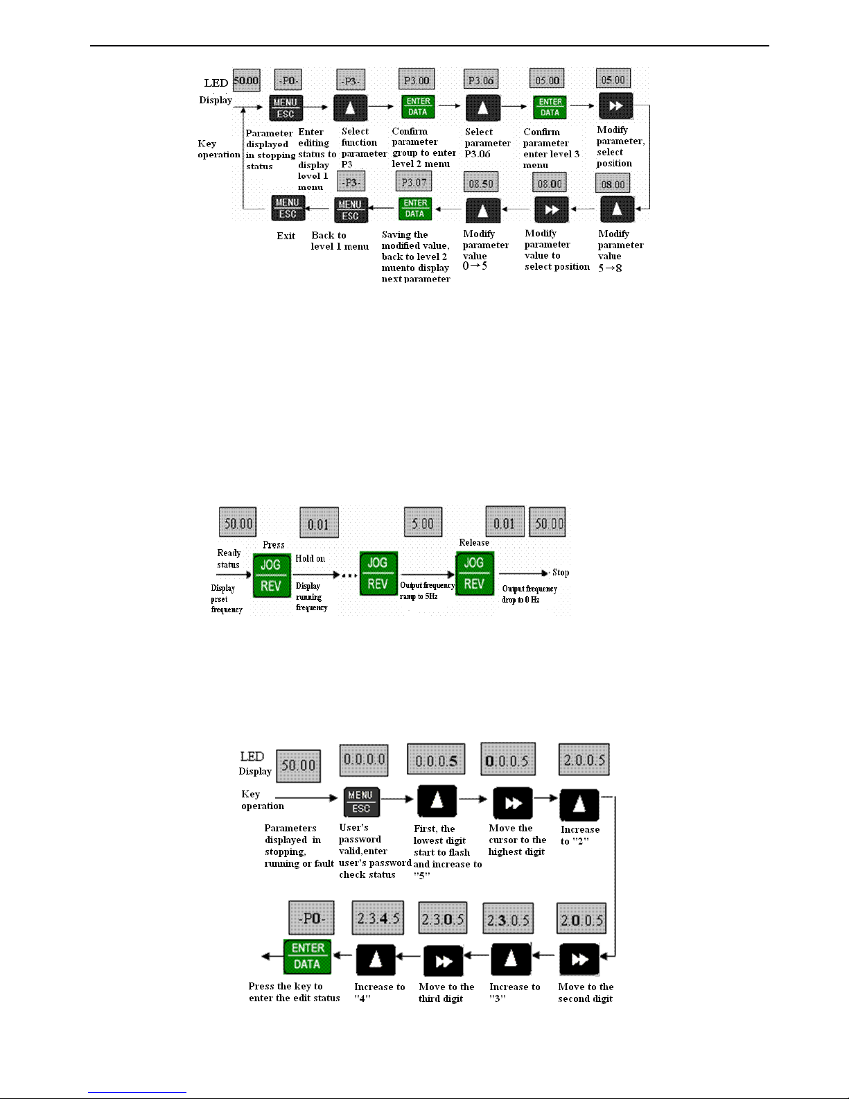
V5 series inverter
34
F
F
F
F ig.
ig.
ig.
ig. 3-8
3-8
3-8
3-8 Parameter
Parameter
Parameter
Parameter editing
editing
editing
editing
In the th ird level menu
,
the parameter can ’ t be changed if none digit of the parameter is flashing, the possible reasons are:
(1) The setting of this parameter can not be changed, such as the actural detected parameters or recorded parameters.
(2) This parameters can only be changed in stopping state and can not be changed in running state.
(3) Parameters have been protected. IfP3.01 is set to
1
or 2, the setting of all the parameters can not be changed
by
wrong
operation. If you really want to change the setting, first set P3.01 to 0.
3
3
3
3
.
.
.
.
Jog
Jog
Jog
Jog
When the inverter in stop state, press JOG key and holde it, the panel will display start output frequency and the frequency
will ramp to 5Hz, then releasing the JOG
key,
the frequency will drop to 0Hz and the inverter will stop.
Fig.
Fig.
Fig.
Fig. 3-9
3-9
3-9
3-9 Jog
Jog
Jog
Jog Operation
Operation
Operation
Operation
4
4
4
4
.
.
.
.
Setting
Setting
Setting
Setting user
user
user
user
’
’
’
’
s
s
s
s password
password
password
password
Setting PF.0
1
as “ 2345 ” and let it as user’s password. The bold digit indicates flashing digit.
Fig.
Fig.
Fig.
Fig. 3-10
3-10
3-10
3-10 Input
Input
Input
Input user
user
user
user
’
’
’
’
s
s
s
s password
password
password
password
LED
Dispaly
Key Operation
Page 41
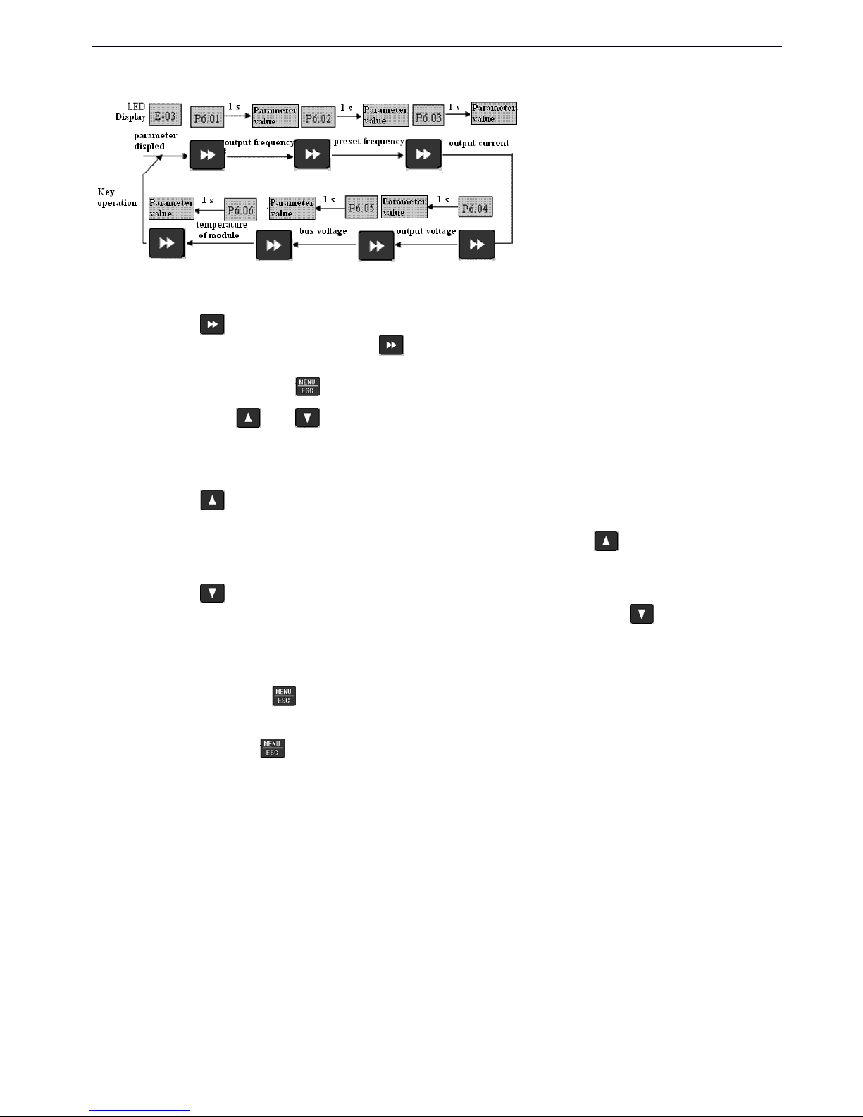
V5 series inverter
35
5
5
5
5
.
.
.
.
Inquiry
Inquiry
Inquiry
Inquiry fault
fault
fault
fault parameters:
parameters:
parameters:
parameters:
Fig.
Fig.
Fig.
Fig. 3-11
3-11
3-11
3-11 Inquiry
Inquiry
Inquiry
Inquiry operation
operation
operation
operation in
in
in
in fault
fault
fault
fault status
status
status
status
Note :
(1)
You
can press key to inquire P6 function parameter group in the status of parameters displayed in fault, the range
of the parameters is P6.01 ~ P6.06
,
when you press
key,
parameter No. will firstly displayed and the parameter value
will be displayed automatically in one second.
(2) While inquiring,
You
can press key to back to fault parameter displayed status.
6
6
6
6
.
.
.
.
Set
Set
Set
Set ting
ting
ting
ting freuqnecy
freuqnecy
freuqnecy
freuqnecy via
via
via
via and
and
and
and
Suppose that the parameters at stop is displaying
,
P0.01=1, the operation mode is shown below:
(1) Frequency adjustment adopt integral mode;
(2) When pressing
,
the digital increase s f rom unit’place of LED, then it carr ies from unit’s place to ten’s place,the
digital of ten’s place starts to increase, as the same, when it carries from ten’s place to hundred’s place, the digital of
hundred’s place starts to increase,so does the digital of thousand
’
s place. If you release and press it again, the digital
will restart to increase from the unit’s place of LED.
(3) When pressing
,
the digital decrease s from unit’s place of LED, then it borrow from ten’s place,the digital of ten’s
place starts to decrease. So does the digital in hundred ’ place and thousand
’
s place.If you realse key and press it again,
it will restart to descrease from the unit’s place of LED.
7
7
7
7
.
.
.
.
Lock
Lock
Lock
Lock the
the
the
the panel
panel
panel
panel
If the panel is unlocked, press key for five seconds can lock the panel.
8
8
8
8
.
.
.
.
Unlock
Unlock
Unlock
Unlock the
the
the
the panel
panel
panel
panel
If the panel is locked, press key for five seconds can unlock the panel.
3-3.
3-3.
3-3.
3-3. Start-up
Start-up
Start-up
Start-up
3-3-1.
3-3-1.
3-3-1.
3-3-1. Checking
Checking
Checking
Checking befor
befor
befor
befor
e
e
e
e
start
start
start
start ing
ing
ing
ing up
up
up
up
Please wire the inverter according to “ Wiring ” in this manual.
3-3-2.
3-3-2.
3-3-2.
3-3-2. Start
Start
Start
Start up
up
up
up the
the
the
the inverter
inverter
inverter
inverter for
for
for
for the
the
the
the first
first
first
first time
time
time
time
After checking the wiring and AC power, switch on the AC power supply to electrify the inverter.The inverter’s panel will
display dynamic screen and then the contactor closes. When the LED displays preset frequency, the initialization of this
inverter is completed.The procedure is shown as Fig.
Page 42
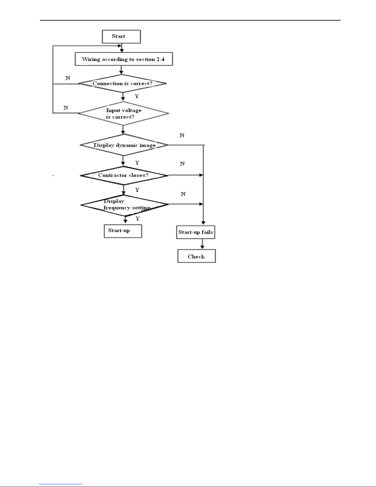
V5 series inverter
36
Fig.
Fig.
Fig.
Fig. 3-12
3-12
3-12
3-12 Procedures
Procedures
Procedures
Procedures of
of
of
of starting
starting
starting
starting the
the
the
the driver
driver
driver
driver for
for
for
for the
the
the
the first
first
first
first time
time
time
time
Page 43
V5 series inverter
37
4
4
4
4 Function
Function
Function
Function Parameters
Parameters
Parameters
Parameters
4-1.
4-1.
4-1.
4-1. Function
Function
Function
Function parameter
parameter
parameter
parameter table
table
table
table
“○”
: Parameters can be changed while running
“×”
: Parameters can not be changed while running
“ *”: Parameters can only be read, user can not changed
1
1
1
1
.
.
.
.
Basic
Basic
Basic
Basic running
running
running
running parameters
parameters
parameters
parameters (
(
(
( G
G
G
G roup
roup
roup
roup P0)
P0)
P0)
P0)
Group
Group
Group
Group P0
P0
P0
P0 : Basic
Basic
Basic
Basic running
running
running
running parameters
parameters
parameters
parameters
Parameter
Parameter
Parameter
Parameter
Name
Name
Name
Name
Setting
Setting
Setting
Setting Range
Range
Range
Range
Minmum
Minmum
Minmum
Minmum
unit
unit
unit
unit
Factory
Factory
Factory
Factory setting
setting
setting
setting
Change
Change
Change
Change
P0.00
Control mode
selection
0 : V/F control
1 : open-loop vector control
1
0
×
P0.01
Frequency setting
mode
0 : Analog potentiometer in the
panel
1 : Increase / Decrease key
2:digit setting 1,via keys on th e
panel
3 : digit setting 2 , via terminal
UP/DOWN
4 : digit setting 3 , via serial port
5 : VI analog input ( VI-GND )
6 : CI analog input ( CI-GND )
7 : Pulse input ( PULSE )
8 : Combined setting mode ( refe r
to P3.00 )10
○
P0.02
Running frequency
in digit mode
P0.19
High frequency limit ~ P0.20 low
frequency limit
0.01HZ
50.00HZ
○
P0.03
Running command
selection
0 : Running frequency via
operation panel control
1 : Teminal control
2 : serial port control
1
0
○
P0.04
Running direction
setting
Unit’s place :
0 : jog forward via panel
1 : jog reverse via panel
Ten’s place :
0 : permit reverse
1 : prohibit reverse
1
00
○
P0.05
Run forward/reverse
dead time
0.0 ~ 120.0s
0.1s
0.1s
○
P0.06
Highest ouput
frequency
50.00Hz ~ 500.00Hz
0.01Hz
50.00Hz
×
P0.07
Basic running
frequency
1.00Hz ~ 500.00Hz
0.01Hz
50.00Hz
×
P0.08
Highest output
voltage
1 ~ 480V1VInverter rated
voltage
×
P0.09
Torque boost
0.0 %~ 30.0 %
0.1 %
2.0 %
○
P0.10
Cut-off frequency
for torque boost
0.00Hz ~ basic running
frequency P0.07
0.00
25.00Hz
○
P0.11
Torque boost mode
0 : manual
1 : automatical
1
0
○
P0.12
Carrier frequency
1.0K ~ 14.0K
0.1K
8.0K
×
P0.13
Acc/Dec direction se
0 : linear Acc/Dec
1
0
×
Page 44
V5 series inverter
38
2
2
2
2
.
.
.
.
Reference
Reference
Reference
Reference frequency
frequency
frequency
frequency parameter
parameter
parameter
parameter (
(
(
( G
G
G
G roup
roup
roup
roup P1)
P1)
P1)
P1)
lection
1 : S curve Acc/Dec
P0.14
Low speed time of S
ramp
10.0 %~ 50.0 %( Acc/Dec time
)
P0.14 + P0.15 < 90 %
0.1 %
20.0 %
○
P0.15
Linear time of S
ramp
10.0 %~ 80.0 %( Acc/Dec time
)
P0.14 + P0.15 < 90 %
0.1 %
60.0 %
○
P0.16
Acc/Dec time unit
0 : second
1 : minute00
×
P0.17
Acc ti me 1
0.1 ~ 6000.0
0.1
10.0
○
P0.18
Dec time 1
0.1 ~ 6000.0
0.1
10.0
○
P0.19
High frequency limit
Low frequency limit ~ highest
output frequency P0.06
0.01Hz
50.00Hz
×
P0.20
Low frequency limit
0.00Hz ~ high frequency limit
0.01Hz
0.00Hz
×
P0.21
Running mode of
low frequency limit
0 : running at low frequency limit
1 : stop
10×
P0.22
V/F curve setting
0 : constant torque curve
1 : torque-reducing curve 1 ( 1. 2
order )
2 : torque-reducing curve 2 ( 1.7
order )
3 : torque-reducing curve 3 ( 2.0
order )
4 : multi-s eg ment V/F curve
10×
P0.23
V/F frequency value
P1
0.00 ~ P0.25
0.01Hz
0.00Hz
×
P0.24
V/F voltage value
V1
0 ~ P0.26
0.1 %
0.0 %
×
P0.25
V/F frequency value
P2
P0.23 ~ P0.27
0.01Hz
0.00Hz
×
P0.26
V/F voltage value
V2
P0.24 ~ P0.28
0.1 %
0.0 %
×
P0.27
V/F frequency value
P3
P0.25 ~ P0.07 basic running
frequency
0.01Hz
0.00Hz
×
P0.28
V/F voltage value
V3
P0.26 ~ 100.0 %
0.1 %
0.0 %
×
Group
Group
Group
Group P1
P1
P1
P1 : reference
reference
reference
reference frequency
frequency
frequency
frequency parameter
parameter
parameter
parameter
Parameter
Parameter
Parameter
Parameter
Name
Name
Name
Name
Setting
Setting
Setting
Setting range
range
range
range
Minmum
Minmum
Minmum
Minmum
unit
unit
unit
unit
Factory
Factory
Factory
Factory setting
setting
setting
setting
Change
Change
Change
Change
P1.00
Time constant of
analog filter
0.01 ~ 30.00s
0.01s
0.20s
○
P1.01
VI G ain of reference
frequency selsector
0.01 ~ 9.99
0.01
1.00
○
P1.02
min reference of VI
0.00 ~ P1.04
0.01V
0.00V
○
P1.03
Frequency
corresponding to
min reference of VI
0.00 ~ high frequency limit
0.01Hz
0.00Hz
○
P1.04
Max reference of VI
P1.04 ~ 10.00V
0.01V
10.00V
○
P1.05
Frequency
corresponding to
max reference of VI
0.00 ~ high frequency limit
0.01Hz
50.00Hz
○
P1.06
Gain of reference
frequency selector of
CI
0.01 ~ 9.99
0.01
1.00
○
Page 45
V5 series inverter
39
3
3
3
3
.
.
.
.
Starting
Starting
Starting
Starting and
and
and
and Braking
Braking
Braking
Braking Prameters
Prameters
Prameters
Prameters (
(
(
( G
G
G
G roup
roup
roup
roup P2
P2
P2
P2 )
)
)
)
P1.07
Min r eferenc e of CI
0.00 ~ P1.09
0.01V
0.00V
○
P1.08
Frequency
corresponding to
min reference of CI
0.00 ~ high frequency limit
0.01Hz
0.00Hz
○
P1.09
Max reference of
CI
P1.07 ~ 10.00V
0.01V
10.00V
○
P1.10
Frequency
corresponding to
max reference of CI
0.00 ~ high frequency limit
0.01Hz
50.00Hz
○
P1.11
Max input pulse
frequency of
PULSE
0.1 ~ 20.0K
0.1K
10.0K
○
P1.12
Min reference of
PULSE
0.0 ~ P1.14
( Max reference of PULSE)
0.1K
0.1K
○
P1.13
Frequency
corresponding to
min reference of
PULSE
0.00 ~ high frequency limit
0.01Hz
0.00Hz
○
P1.14
Max reference of
PULSE
P1.12 ( Min reference of PULSE )~
P1.11 ( Max input frequency )
0.1K
10.0K
○
P1.15
Frequency
corresponding to
max reference of
PULSE
0.00 ~ high frequency limit
0.01Hz
50.00Hz
○
P1.16
Input mode of CI
0 : 4 ~ 20mA
1 : 0 ~ 10V
-0○
Group
Group
Group
Group P2
P2
P2
P2 : Starting
Starting
Starting
Starting and
and
and
and Braking
Braking
Braking
Braking Prameters
Prameters
Prameters
Prameters
Parameter
Parameter
Parameter
Parameter
Name
Name
Name
Name
Range
Range
Range
Range
Minmum
Minmum
Minmum
Minmum
unit
unit
unit
unit
Factory
Factory
Factory
Factory setting
setting
setting
setting
Change
Change
Change
Change
P2.00
Starting mode
0 : Start from the starting
frequency
1 : Brake first and then start
from the starting frequency
2 : Start on the fly
10×
P2.01
Starting frequency
0.20 ~ 20.00Hz
0.01Hz
0.50Hz
○
P2.02
Holding time of starting
frequency
0.0 ~ 30.0s
0.1s
0.0s
○
P2.03
DC injection braking
current at start
0.0 ~ 80.0 %
0.1 %
0 %
○
P2.04
DC injection braking time
at start
0.0 ~ 60.0s
0.1s
0.0s
○
P2.05
Stopping mode
0 : Dec-to-stop
1 : Coast-to-stop
2
:
Dec-to-stop +DC brakin g
1
0
×
P2.06
DC injection braking initial
0.0 ~ 15.00Hz
0.0Hz
3.00Hz
○
Page 46
V5 series inverter
40
4
4
4
4
.
.
.
.
Auxiliary
Auxiliary
Auxiliary
Auxiliary running
running
running
running parameters
parameters
parameters
parameters (
(
(
( G
G
G
G roup
roup
roup
roup P3
P3
P3
P3 )
)
)
)
frequency at stop
P2.07
DC injection braking
waiting time at stop
0.0 ~ 60.0s
0.1s
0.0s
○
P2.08
DC injection braking
current at stop
0.0 ~ 80.0 %
0.1 %
0.0 %
○
Group
Group
Group
Group P3
P3
P3
P3 : Auxiliary
Auxiliary
Auxiliary
Auxiliary running
running
running
running parameters
parameters
parameters
parameters
Parameter
Parameter
Parameter
Parameter
Name
Name
Name
Name
Range
Range
Range
Range
Minmum
Minmum
Minmum
Minmum
unit
unit
unit
unit
Factory
Factory
Factory
Factory
setting
setting
setting
setting
Change
Change
Change
Change
P3.00
Combination of
frequency input
0 : VI + CI
1 : VI - CI
2 : E xternal pulse reference + VI +
Increase / Decrease k ey reference
3 : E xternal pulse reference - VI -
Increase / Decrease k ey reference
4 : E xternal pulse reference + CI
5 : E xternal pulse reference - CI
6 : RS485 + VI + Increase / Decrease
k ey reference
7 : RS485 - VI - Increase / Decrease
Key reference
8 : RS485 + CI + Increase / Decrease
k ey reference
9 : RS485 - CI - Increase / Decrease
k ey reference
10 : RS485 + CI + E xternal pulse
reference
11 : RS485 - CI - E xternal pulse
reference
12 : RS485 + VI + E xternal pulse
reference
13 : RS485 - VI - E xternal pulse
reference
14 : VI + CI + Increase / Decrease k ey
reference + Digital setting
15 : VI + CI - Increase / Decrease k ey
reference + Digital setting
16 : MAX ( VI , CI )
17 : MIN ( VI , CI )
18 : MAX ( VI , CI , PULSE )
19 : MIN ( VI , CI , PULSE )
20 : VI , CI none-zero is valid , V I
priority
1
0
×
Page 47
V5 series inverter
41
P3.01
Parameter initial ization
locking up
Unit’s place :
0: A ll parameters are allowed
modifying
1: Only P3.01 can be modified
2: Only P0.02 and P3.01 can be
modified
Ten’s place :
0 : disable d
1 : Res tore to factory setting
2 : Clear fault record
1
0 0
×
P3.02
Parameter copy
0: disabled
1: parameter upload
2: parameter download
Note : Function is still in developing
10×
P3.03
Auto energy-saving
function
0 : disabled
1 : Enabled
1
0
×
P3.04
AVR
function
0 : disabled
1 : enable all the time
2 : Disabled in Dec process
10×
P3.05
Gain of slip
compensation
0 ~ 150 %
1 %
0 %
×
P3.06
Jog operating frequency
0.10 ~ 50.00H z
0.01H z
5.00H z
○
P3.07
Acc time of jog operation
0.1 ~ 60.0 s
0.1 s
5 .0 s
○
P3.08
Dec time of jog operation
0.1 ~ 60.0 s
0.1 s
5 .0 s
○
P3.09
Communication
config
LED unit’s place : baud rate selection
0 : 1200BPS
1 : 2400BPS
2 : 4800BPS
3 : 9600BPS
4 : 19200BPS
5 : 38400BPS
LED ten’s place : data format
0 : 1 - 7 - 2 foramt , no parity check
1 : 1 - 7 - 1 format , Odd
2 : 1 - 7 - 1 format , Even
3 : 1 - 8 - 2 format , None
4 : 1 - 8 - 1 format , Odd
5 : 1 - 8 - 1 format , Even
6 : 1 - 8 - 1 format , None
( When use Modbus-RTU
communication mode , please select
data mode 3 ~ 6 。 )
LED hundred’s place :
undefined
1
054
×
P3.10
Local address
0 ~ 248
0 : broadcast address
248 : inverter as the host address
11×
P3.11
Delay for responding to c
0.0 ~ 1000 .0s
0.1 s
0.0 s
×
Page 48
V5 series inverter
42
ontrol PLC
0.0 : Detection disabled
P3.12
Delay for responding to
control PLC
0 ~ 1000ms15ms
×
P3.13
Reference proportion of
communication frequency
0.01 ~ 1.00
0.01
1.00
×
P3.14
Acc time 2
0.1 ~ 6000.0
0.1
1 0.0
○
P3.15
Dec time 2
0.1 ~ 6000.0
0.1
1 0.0
○
P3.16
Acc time 3
0.1 ~ 6000.0
0.1
1 0.0
○
P3.17
Dec time 3
0.1 ~ 6000.0
0.1
1 0.0
○
P3.18
Acc time 4
0.1 ~ 6000.0
0.1
1 0.0
○
P3.19
Dec time 4
0.1 ~ 6000.0
0.1
1 0.0
○
P3.20
Acc time 5
0.1 ~ 6000.0
0.1
1 0.0
○
P3.21
Dec time 5
0.1 ~ 6000.0
0.1
1 0.0
○
P3.22
Acc time 6
0.1 ~ 6000.0
0.1
1 0.0
○
P3.23
Dec time 6
0.1 ~ 6000.0
0.1
1 0.0
○
P3.24
Acc time 7
0.1 ~ 6000.0
0.1
1 0.0
○
P3.25
Dec time 7
0.1 ~ 6000.0
0.1
1 0.0
○
P3.26
Multi-frequency 1
Lower limit frequency ~ upper limit of
frequency
0.01H z
5.00H z
○
P3.27
Multi-frequency 2
Lower limit frequency ~ upper limit of
frequency
0.01H z
10.00H z
○
P3.28
Multi-frequency 3
Lower limit frequency ~ upper limit of
frequency
0.01H z
20.00H z
○
P3.29
Multi-frequency 4
Lower limit frequency ~ upper limit of
frequency
0.01H z
30.00H z
○
P3.30
Multi-frequency 5
Lower limit frequency ~ upper limit of
frequency
0.01H z
40.00H z
○
P3.31
Multi-frequency 6
Lower limit frequency ~ upper limit of
frequency
0.01H z
45.00H z
○
P3.32
Multi-frequency 7
Lower limit frequency ~ upper limit of
frequency
0.01H z
50.00H z
○
P3.33
Jump frequency 1
0.00 ~ 50 0.00H z
0.01H z
0.00H z
×
P3.34
Range of jump frequency
1
0.00 ~ 30.00H z
0.01H z
0.00H z
×
P3.35
Jump frequency 2
0.00 ~ 50 0.00H z
0.01H z
0.00H z
×
P3.36
Range of jump frequency
2
0.00 ~ 30.00H z
0.01H z
0.00H z
×
P3.37
Jump frequency 3
0.00 ~ 50 0.00H z
0.01H z
0.00H z
×
P3.38
Range of jump frequency
3
0.00 ~ 30.00H z
0.01H z
0.00H z
×
P3.39
Set running time
0 ~ 65.535K hour
0.001 K
0 .000K
○
P3.40
Accumulate r unning time
0 ~ 65.535K hour
0.001K
0 .000K
*
P3.41
Display parameters
selection 1
0000 ~ FFFF
Unit’s place : b-09 ~ b - 12
Ten’s place : b-13 ~ b - 16
Hundred’s place : b-17 ~ b - 20
Thousand’s place : b-21 ~ b - 24
1
0000
○
P3.42
Display parameters select
0000 ~ FFFF10000
○
Page 49
V5 series inverter
43
5
5
5
5
.
.
.
.
Function
Function
Function
Function parameters
parameters
parameters
parameters of
of
of
of terminal
terminal
terminal
terminal (Group
(Group
(Group
(Group P4)
P4)
P4)
P4)
ion 2
Unit’s place : b-25 ~ b - 28
Ten’s place : b-29 ~ b-32
Hundred’s place : b-33 ~ b-36
Thousand’s place : b-37 ~ b-40
P3.43
Display parameters
selection 3
0000 ~ 4040
Ten’s place, unit’s pladce : stop
displayed parameter selection
Thousand’s place, hundred’s place :
run displayed parameter selection
1
0001
○
P3.44
D isplay
coefficient without unit
0.1 ~ 60.0
0.1
1.0
○
P3.45
JOG/REV shift control
mode
0 : select JOG to start jog
1 : select REV start reverse
10×
Group
Group
Group
Group P4
P4
P4
P4 : Function
Function
Function
Function Parameters
Parameters
Parameters
Parameters of
of
of
of T eriminal
Teriminal
Teriminal
Teriminal
Parameter
Parameter
Parameter
Parameter
Name
Name
Name
Name
Range
Range
Range
Range
Minmum
Minmum
Minmum
Minmum
unit
unit
unit
unit
Factory
Factory
Factory
Factory
setting
setting
setting
setting
Change
Change
Change
Change
P4.00
Function selection of
i nput terminal X1
0 : Control terminal free
1 : Multi-step speed
control terminal 1
2:Multi-step speed contro l
terminal 2
3:Multi-step speed contro l
terminal 3
4 : Exteral terminal for
forward jog operation
5 : Exteral terminal for
reverse jog operation
6:Acc/Dec time terminal 1
7:Acc/Dec time terminal 2
8:Acc/Dec time terminal 3
9:3-wire operation contro l
10 : Coast-to-stop ( FRS
)
11:External stop comman d
12 : DC injection braking
command DB
13 : Inverter run ning
prohibit
14 : Frequency ramp
up ( UP )
15 : Frequency ramp down
( DOWN )
16 : Acc/Dec prohibit
17 : Reset signal ( clear
fault )
18 : External fault signal
normally open input
11×
Page 50
V5 series inverter
44
19 : F requency selector 1
20 : F requency selector 2
21 : F requency selector 3
22 : T erminal control mode
is forcibly enabled
23:C ontrol mode selector 1
24:C ontrol mode selector 2
25:Start traverse operatio n
26 : Reset the traverse
operation status
27 : Close-loop disabled
28 : Pause the PLC
operation
29 : PLC disabled
30 : Reset PLC stopping
status
31:Frequency reference is
input via CI
32 : Counter’s trig signal
input
33 : Counter’s zero-
cleaning signal input
34:External interrupt inpu t
35 : P ulse frequency inpu t
( only valid for X6 )
36 : A c tual length clea r ing
input
P4.01
Function selection of
input terminal X2
As above
12×
P4.02
Function selection of
input terminal X3
As above
1
3
×
P4.03
Function selection of
input terminal X 4
As above
110×
P4.04
Function selection of
input terminal X 5
As above
117×
P4.05
Function selection of
input terminal X 6
As above
118×
P4.06
Function selection of
input terminal X7 FWD
As above
1
0
×
P4.07
Function selection of
input terminal X8 REV
As above
10×
P4.08
FWD/REV
Operation mode selection
0 : 2-wire control mode 1
1 : 2-wire control mode 2
2 : 3-wire control mode 1
3 : 3-wire control mode 2
1
0
×
P4.09
UP/DN speed rate
0.01 - 99.99Hz/s
0.01
1.00Hz/s
○
P4.10
Bi-direction open-
collector output terminal
OC
0:Inverter
running
( RUN
)
1 : Frequency arriving
signal ( FAR )
10×
Page 51
V5 series inverter
45
2 : Frequency detection
threshold ( FDT1 )
3 : Frequency detection
threshold ( FDT2 )
4 : Overload pre-
alarm ( OL )
5 : Inverter under voltage
locking ( LU )
6 : External fault
stop ( EXT )
7:Output frequency arri ve
upper limit of ( FH )
8 : Output frequency arrive
lower limit ( FL )
9 : Inverter zero speed
running
10 : Simple PLC Pause
running finished
11 : PLC is finished after
one cycle running
12 :Specified counting
value arriving
13 : Mid counting value
arriving
14:Inverter Ready runnin g
finished ( RDY )
15 : Inverter fault
16 : Start frenquence
running time
17 : Start DC injection
braking time
18 : Stop braking time
19
:
High and lower limit s
of traverse operating
frequency
20:set running time arriv e
P4.11
Relay output selector
As above
115×
P4.12
Detecting range of
f requen cy arrive ( FAR
)
0.00 ~ 50.00Hz
0.01Hz
5.00Hz
○
P4.13
FDT1 ( frequency ) lev el
0.00 ~ upper limit of of
frequency
0.01Hz
10.00Hz
○
P4.14
FDT1 lag
0.00 ~ 50.00Hz
0.01Hz
1.00Hz
○
P4.15
FDT2 ( frequency ) level
0.00 ~ upper limit of of
frequency
0.01Hz
10.00Hz
○
P4.16
FDT2 lag
0.00 ~ 50.00Hz
0.01Hz
1.00Hz
○
P4.17
Analog output ( AO )
0:O utput frequency ( 0 ~
)
1 : Output current ( 0 ~ 2
times of rated current )
2:Output
voltage
( 0 ~ 1. 2 i
10○
Page 52
V5 series inverter
46
6
6
6
6
.
.
.
.
Protective
Protective
Protective
Protective function
function
function
function parameters
parameters
parameters
parameters (Group
(Group
(Group
(Group P5
P5
P5
P5 )
)
)
)
nverter’s rated voltage )
3:Bus voltage ( 0 ~ 800V
)
4 : PID reference
5 : PID feedback
6 : VI ( 0 ~ 10V )
7 : CI(0 ~ 10V/4 ~ 20mA)
P4.18
Analog
output
( AO)gai n
setup
0.50 ~ 2.00
0.01
1.00
○
P4.19
AO output mode
0 : 4 ~ 20mA
1 : 0 ~ 10V
-
1
○
P4.20
DO output terminal
0 : Output frequency ( 0 ~
upper limit of of
frequency )
1 : Output current ( 0 ~ 2
times motor rated current )
2 : Output voltage ( 0 ~ 1. 2
inverter’s rated voltage )
3:B us voltage ( 0 ~ 800V
)
4 : PID reference
5 : PID feedback
6 : VI ( 0 ~ 10V )
7 : CI(0 ~ 10V/4 ~ 20mA)
10○
P4.21
DO max pulse oupt
frequency
0.1K ~ 20.0K ( Max:
20KHz )
0.1KHz
10.0KHz
○
P4.22
preset counting value
arriving
P4.23 ~ 9999
10○
P4.23
Mid counting value
arriving
0 ~ P4.22
1
0
○
P4.24
Overload pre-alarm
detection level
20 %~ 200 %
1
130 %
○
P4.25
Delay time of over load
pre-alarm
0.0 ~ 20.0s
0.1s
5.0s
○
Group
Group
Group
Group P5
P5
P5
P5 : Protective
Protective
Protective
Protective function
function
function
function parameters
parameters
parameters
parameters
Parameter
Parameter
Parameter
Parameter
Name
Name
Name
Name
Range
Range
Range
Range
Minmum
Minmum
Minmum
Minmum
unit
unit
unit
unit
Factory
Factory
Factory
Factory setting
setting
setting
setting
Change
Change
Change
Change
P5.00
Motor overload protection
mod e selection
0 : Inverter locking output
1 : D isable d
10×
P5.01
Motor’s overload
protection coefficient
20 ~ 120 %
1
100 %
×
P5.02
Protection of over load at
stall
0 : Disabled
1 : Enabled
1
1
×
P5.03
Over voltage point at stall
380V : 120 ~ 150 %
220V : 110 ~ 130 %
1 %
140 %
120 %
○
P5.04
Auto current limiting
threshold
110 %~ 200 %
1 %
150 %
×
Page 53
V5 series inverter
47
7
7
7
7
.
.
.
.
Fault
Fault
Fault
Fault record
record
record
record ing
ing
ing
ing parameter
parameter
parameter
parameter (Group
(Group
(Group
(Group P6)
P6)
P6)
P6)
8
8
8
8
.
.
.
.
Close-loop
Close-loop
Close-loop
Close-loop control
control
control
control parameter
parameter
parameter
parameter s
s
s
s (Group
(Group
(Group
(Group P7)
P7)
P7)
P7)
P5.05
Frequeny decrease rate
when current limiting
0.00 ~ 99.99Hz/s
0.01Hz/s
10.00Hz/s
○
P5.06
Auto current limiting
selection
0 : D isabled in constant speed
1
:
E nabled in constant spee d
Note : Enabled at Acc/Dec
11×
P5.07
setting of the restart after
power off
0 : Disabled
1 : Enabled
1
0
×
P5.08
Holding time of restart
after power off
0.0 ~ 10.0s
0.1s
0.5s
×
P5.09
Auto reset times of fault
0 ~ 10
0 : N
o
auto reset
function ( Note : overload an d
overheat have no recovery
function )
10×
P5.10
Auto reset interval of fault
0.5 ~ 20.0s
0.1s
5.0s
×
Group
Group
Group
Group P6
P6
P6
P6 : Fault
Fault
Fault
Fault recording
recording
recording
recording parameter
parameter
parameter
parameter
Parameter
Parameter
Parameter
Parameter
Name
Name
Name
Name
Description
Description
Description
Description
Minmun
Minmun
Minmun
Minmun unit
unit
unit
unit
Factory
Factory
Factory
Factory
setting
setting
setting
setting
Change
Change
Change
Change
P6.00
Previous fault record
Previous fault record
10*
P6.01
Output frequency of
previous fault
Output frequency of previous fault
record
0.01Hz0*
P6.02
Setting frequency of
previous fault
Setting frequency of previous fault
record
0.01Hz0*
P6.03
Output current of previous
fault
Output current of previous fault
0.1A0*
P6.04
Output voltage of previous
fault
Output voltage of previous fault
1V0*
P6.05
DC injectiong bus voltage
of previous fault
DC injectiong bus voltage of
previous fault
1V0*
P6.06
Module temperature of
previous fault
Module temperature of previous
fault
10C0*
P6.07
2 latest fault record
2 latest fault record
10*
P6.08
3 latest fault record
3 latest fault record
10*
P6.09
4 latest fault record
4 latest fault record
10*
P6.10
5 latest fault record
5 latest fault record
10*
P6.11
6 latest fault record
6 latest fault record
10*
Group
Group
Group
Group P7
P7
P7
P7 : Close-loop
Close-loop
Close-loop
Close-loop control
control
control
control parameter
parameter
parameter
parameter s
s
s
s
Parameter
Parameter
Parameter
Parameter
Name
Name
Name
Name
Range
Range
Range
Range
Minmum
Minmum
Minmum
Minmum
unit
unit
unit
unit
Factory
Factory
Factory
Factory
setting
setting
setting
setting
Change
Change
Change
Change
P7.00
Close-loop function selection
0 : Disabled
1 : Enabled
1
0
×
P7.01
Reference channel selection
0 : Digit input
1 : VI (0~10V)
11○
Page 54
V5 series inverter
48
9
9
9
9
.
.
.
.
Simple
Simple
Simple
Simple PLC
PLC
PLC
PLC operation
operation
operation
operation parameters
parameters
parameters
parameters (
(
(
( Group
Group
Group
Group P8
P8
P8
P8 )
)
)
)
2 : Analog reference by CI
P7.02
Feedback channel selection
0 : VI (0~10V)
1 : Analog reference by CI
2 : VI+CI
3 : VI-CI
4 : Min { VI , CI }
5 : Max { VI , CI }
11○
P7.03
Reference filter
0.01 ~ 50.00s
0.01s
0.50s
○
P7.04
Feedback f ilter
0.01 ~ 50.00s
0.01s
0.50s○P7.05
S et reference in digital mode
0.00 ~ 10.00V
0.01V
0.00V○P7.06
Mi n reference
0.0 ~ Max reference P7.08
0.1 %
0.0 %
○
P7.07
Feedback value corresponding
to min reference
0.0 ~ 100.0%
0.1 %
0.0 %
○
P7.08
Max reference
Min reference P7.06 ~ 100.0 %
0.1 %
100.0 %
○
P7.09
Feedback va lue corresponding
to max reference
0.0 ~ 100.0 %
0.1 %
100.0 %
○
P7.10
Proportional KP
0.000 ~ 9.999
0.001
0.050○P7.11
Integral KI
0.001 ~ 9.999
0.001
0.050
○
P7.12
Sampling cycle T
0.01 ~ 10.00S
0.01
1.00
○
P7.13
Limits of deviation
0.0 ~ 20.0 %
1 %
2.0 %
○
P7.14
Close loop adjustment
characteristic
0: Forward
1: Reverse
Note : relationship between reference temperature and
speed
10×
P7.15
Integral adjustment selection
0 : Stop integral adjustment selection when the
frequency reaches upper limit or lower limit s
1:Continue the integral adjustment selection when th e
frequency reaches hig h limit or lower limit s
1
0
×
P7.16
Close loop preset frequency
0 ~ upper limit of of frequency
0.01Hz
0.00Hz○P7.17
Holding time of close loop
0.0 ~ 250.0s
0.1s
0.1s
×
P7.18
Threhold of zero-frequency
operation
0.00 ~ 500.00Hz
0.01Hz
0.01Hz
×
P7.19
Hysteresis of zero-frequency
operation
0.00 ~ 500.00Hz
0.01Hz
0.01Hz
×
Group
Group
Group
Group P8
P8
P8
P8 : Simple
Simple
Simple
Simple PLC
PLC
PLC
PLC operation
operation
operation
operation parameters
parameters
parameters
parameters
Parameters
Parameters
Parameters
Parameters
Name
Name
Name
Name
Range
Range
Range
Range
Minmum
Minmum
Minmum
Minmum
unit
unit
unit
unit
Factory
Factory
Factory
Factory
setting
setting
setting
setting
Change
Change
Change
Change
P8.00
Simple PLC operation
mode selection
0000 ~ 11 13
Unit’s place : mode selection
0 : Disabled
1 : Stop after single cycle of operation
2 : Holding at the final value after sing le cycle of
operation
3 : Operate continuously
Ten’s place :
PLC restarting mode after stopping
1
0000
×
Page 55
V5 series inverter
49
10
10
10
10
.
.
.
.
Traverse
Traverse
Traverse
Traverse and
and
and
and measure
measure
measure
measure function
function
function
function parameter
parameter
parameter
parameter s
s
s
s (Group
(Group
(Group
(Group 9)
9)
9)
9)
0 : Run again f rom stage 1
1 : Continue to run from the stopping stage
Hundred’s place :
Save at power off
0 : Not saving
1 : Save the time and frequency at power off
Thousand’s place : Selecting the unit of time
0: second
1: minute
P8.01
Stage 1 setup
000 ~ 621
Unit’s place of LED : frequency setup
0 : Multi i ( i = 1 ~ 7 )
1: Frequency is de cide by P0.01
Ten’s place of LED : Operating direction selection
0 : Run fo rward
1 : R un r everse
2 : Decided by operating instructions
Hundred’s place of LED : Acc/Dec time selection
0 : Acc/Dec time 1
1 : Acc/Dec time 2
2 : Acc/Dec time 3
3 : Acc/Dec time 4
4 : Acc/Dec time 5
5 : Acc/Dec time 6
6 : Acc/Dec time 7
1
000
○
P8.02
Operating time in stage 1
0.1 ~ 6000.0
0.1
10.0
○
P8.03
Stage 2 setup
000 ~ 621
1
000○P8.04
Operating time in stage 2
0.1 ~ 6000.0
0.1
10.0
○
P8.05
Stage 3 setup
000 ~ 621
1
000
○
P8.06
Operating time in stage 3
0.1 ~ 6000.0
0.1
10.0
○
P8.07
Stage 4 setup
000 ~ 621
1
000
○
P8.08
Operating time in stage 4
0.1 ~ 6000.0
0.1
10.0
○
P8.09
Stage 5 setup
000 ~ 621
1
000○P8.10
Operating time in stage 5
0.1 ~ 6000.0
0.1
10.0
○
P8.11
Stage 6 setup
000 ~ 621
1
000
○
P8.12
Operating time in stage 6
0.1 ~ 6000.0
0.1
10.0
○
P8.13
Stage 7 setup
000 ~ 621
1
000
○
P8.14
Operating time in stage 7
0.1 ~ 6000.0
0.1
10.0
○
Group
Group
Group
Group P9
P9
P9
P9 : Traverse
Traverse
Traverse
Traverse and
and
and
and measure
measure
measure
measure function
function
function
function parameters
parameters
parameters
parameters
Parameters
Parameters
Parameters
Parameters
Name
Name
Name
Name
Range
Range
Range
Range
Minmum
Minmum
Minmum
Minmum unit
unit
unit
unit
Factory
Factory
Factory
Factory setting
setting
setting
setting
Change
Change
Change
Change
P9.00
Traverse function selection
0 : Disabled
1 : Enabled
1
0
×
P9.01
Traverse operat ion control
mode
00 ~ 11
Unit’s place of LED : Start mode
0 : Auto mode
100×
Page 56
V5 series inverter
50
11
11
11
11 .
.
.
. Vector
Vector
Vector
Vector control
control
control
control parameters
parameters
parameters
parameters
( Group
Group
Group
Group PA
PA
PA
PA )
1 : Manual mode
Ten’s place of LED : Amplitude control
0 : V ariable amplitude
1 : Fixed amplitude
P9.02
Pre-traverse frequecncy
0.00 ~ 500.00Hz
0.01Hz
0.00Hz
○
P9.03
Waiting time before pre-
traverse frequency
0.0 ~ 3600.0s
0.1s
0.0s
○
P9.04
Traverse operating amplitude
0.0 ~ 50.0 %
0.1 %
0.0 %
○
P9.05
Jitter frequency
0.0 ~ 50.0 %
( with reference to P9.04 )
0.1 %
0.0 %
○
P9.06
Traverse operating cycle
0.1 ~ 999.9s
0.1s
10.0s
○
P9.07
Rising time of trangle wave
0.0 ~ 98.0 %
( with )
0.1 %
50.0 %
○
P9.08
Reference length
0.000 ~ 65.535(km)
0.001km
0.000km
○
P9.09
Actual length
0.0 ~ 65.535km
( Saving at power off )
0.001km
0.000km
○
P9.10
Times of length
0.001 ~ 30.000
0.001
1.000
○
P9.11
correction coefficient of
length
0.001 ~ 1.000
0.001
1.000
○
P9.12
Perimeter of shaft
0.01 ~ 100.00cm
0.01cm
10.00cm
○
P9.13
Number of pulses per
revolution
1 ~ 9999
1
1
○
Group
Group
Group
Group P A
PA
PA
PA : Vector
Vector
Vector
Vector Control
Control
Control
Control Parameters
Parameters
Parameters
Parameters
Parameter
Parameter
Parameter
Parameter
Name
Name
Name
Name
Range
Range
Range
Range
Minmum
Minmum
Minmum
Minmum
unit
unit
unit
unit
Factory
Factory
Factory
Factory setting
setting
setting
setting
Change
Change
Change
Change
PA.00
Motor auto-tu n e
0 : No tu n e
1 : auto tune
10×
PA.01
R ated voltage of motor
0 ~ 400V1Dependent on
inverter’s model
×
PA.02
R ated current of motor
0.01 ~ 500.00A
0.01A
Dependent on
inverter’s model
×
PA.03
R ated frequency of motor
1 ~ 99Hz
1Hz
Dependent on
inverter’s model
×
PA.04
Rated rot ated speed of motor
1 ~ 9999 r/min
1r/min
Dependent on
inverter’s model
×
PA.05
Polarity of motor
2 ~ 481Dependent on
inverter’s model
×
PA.06
Stator inducta nce of motor
0.1 ~ 5000.0mH
0.1mH
Dependent on
inverter’s model
×
PA.07
Rotor inductance of motor
0.1 ~ 5000.0mH
0.1mH
Dependent on
inverter’s model
×
PA.08
Exciting induction of motor
0.1 ~ 5000.0mH
0.1mH
Dependent on
inverter’s model
×
Page 57
V5 series inverter
51
12
12
12
12 .
.
.
. Specail
Specail
Specail
Specail Application
Application
Application
Application function
function
function
function parameters
parameters
parameters
parameters (Group
(Group
(Group
(Group PB
PB
PB
PB )
)
)
)
13
13
13
13
.
.
.
.
Factory
Factory
Factory
Factory setting
setting
setting
setting (Group
(Group
(Group
(Group PF
PF
PF
PF )
)
)
)
PA.09
Stator resistance of motor
0.001 ~ 50.000 Ω
0.001 Ω
Dependent on
inverter’s model
×
PA.10
Rotor resistance of motor
0.001 ~ 50.000 Ω
0.001 Ω
Dependent on
inverter’s model
×
PA.11
Over current protection
coeff icient of torque
0 ~ 15
1
15
×
PA.12
Percentage adjustment
coefficient of speed deviation
50 ~ 120
185×
PA.13
Integral adjustment coefficient
of speed deviation
100 ~ 500
1
360
×
PA.14Vector torque boost
100 ~ 150
1
80×PA.15
Reversed
000
×
PA.16
Reversed
1 ~ 514
×
PA.17
Reversed ( excitation)
100 ~ 150
1
100
×
PA.18
Reversed
1501150
×
PA.19
Reversed
0 ~ 210
Group
Group
Group
Group PB
PB
PB
PB : Specail
Specail
Specail
Specail Application
Application
Application
Application function
function
function
function parameters
parameters
parameters
parameters
Parameter
Parameter
Parameter
Parameter
Name
Name
Name
Name
Range
Range
Range
Range
Minmum
Minmum
Minmum
Minmum unit
unit
unit
unit
Factory
Factory
Factory
Factory
setting
setting
setting
setting
Change
Change
Change
Change
PB.00
Jog frequency source
0 ~ 4
0 : P3.06
1 : Panel poten t iometer
2 : P0.02
3 : VI
4 : CI
00○
PB.01
selecti on of f orward/
r everse dead time
0 、 1
0 : Dead time is enabled ( Min 0.1S)
1 : dead time can be set to
0 ( P0.05=0.0S 、 P0.20 ≥ 0.5Hz is
needed )
10○
PB.02
I nverter type select
0: G type(normal)
1: P type( wind machine,water pump,
power increase s 1 level )
N ote: set as 1, P0.22 must set to 3.
1
0
×
PB.03
S hort the run point
before power on, set the
run m ode
0: after inverter is power on, run
immediately
1: after inverter is power on, cut off
the point and connect again to run
11×
Group
Group
Group
Group PP
PP
PP
PP : Factory
Factory
Factory
Factory Setting
Setting
Setting
Setting
Parameter
Parameter
Parameter
Parameter
Name
Name
Name
Name
Range
Range
Range
Range
Minmum
Minmum
Minmum
Minmum
unit
unit
unit
unit
Factory
Factory
Factory
Factory setting
setting
setting
setting
Change
Change
Change
Change
PF.00
Default password
---
*
PF.01
User’s password
0 : With no password protection
0001 - 9999 : passwor protection
1
0000
○
Page 58
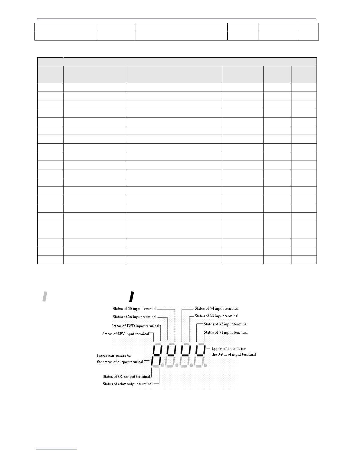
V5 series inverter
52
14
14
14
14
.
.
.
.
B
B
B
B — Monitor
Monitor
Monitor
Monitor function
function
function
function parameters
parameters
parameters
parameters
Note
Note
Note
Note : The corresponding relationship of monitor parameter input/output terminal s and their status display are shown
below:
“ ” shows dis able d ( lamp off
) ,
“ ” shows enabled ( lamp on )
PF.02
Software version
---
*
PF.03 ~ PF.10
Reversed
---
*
B
B
B
B — Monitor
Monitor
Monitor
Monitor function
function
function
function parameters
parameters
parameters
parameters
Code
Code
Code
Code
Name
Name
Name
Name
Description
Description
Description
Description
Minmum
Minmum
Minmum
Minmum
unit
unit
unit
unit
Factory
Factory
Factory
Factory
setting
setting
setting
setting
Change
Change
Change
Change
b-00
Output frequency
Present output frequency
0.01Hz
*
b-01
Reference frequency
Presetn reference frequency
0.01Hz*b-02
Output voltage
Valid
value of present output voltage
1V
*
b-03
Output current
Valid
value of present output current
0.1A
*
b-04
Bus voltage
P resent D C bus voltage
1V
*
b-05
Module temperature
IGBT Temperature of heatsink
10C
*
b-06
Motor overload speed
Present motor overload speed
1r/min
*
b-07
Operating time
one c ontinusly operating time of inverter
1 hour*b-08
Input/output terminal’s status
Digital input/output terminal’s status
——
*
b-09
Analog input VI
Value
of analog input VI
0.01V
*
b-10
Analog input CI
Value
of analog input CI
0.01V
*
b-11
External p ulse input
Input value of external pulse range
1ms
*
b-12
Inverter rated current
Inverter rated current
0.1A
*
b-13
Inverter rated voltage
Inverter rated voltage
1V*b-14
no unit dispaly
no unit dispaly
1
*
b-15
Inverter power class
Inverter power class
-
*
b-16
Display present counter
value
Display present counter value
-
*
b-17
Reversed
--*
……
Reversed
--*
b-40
Reversed
--*
Page 59

V5 series inverter
53
Page 60
V5 series inverter
54
4-2.
4-2.
4-2.
4-2. Parameter
Parameter
Parameter
Parameter d
d
d
d escription
escription
escription
escription
4-2-1
4-2-1
4-2-1
4-2-1
.
.
.
.
Basic
Basic
Basic
Basic operating
operating
operating
operating function
function
function
function parameters
parameters
parameters
parameters ( Group
Group
Group
Group P0
P0
P0
P0 )
0
0
0
0 : V/F
V/F
V/F
V/F control
control
control
control
1
1
1
1 : Open
Open
Open
Open loop
loop
loop
loop vector
vector
vector
vector control
control
control
control
0
0
0
0 : Panel
Panel
Panel
Panel analog
analog
analog
analog potentiometer
potentiometer
potentiometer
potentiometer setting
setting
setting
setting
1
1
1
1 : and
and
and
and keys
keys
keys
keys on
on
on
on the
the
the
the panel
panel
panel
panel
Y
ou can set the reference frequency via and keys on the panel .
2
2
2
2 : Keyboard
Keyboard
Keyboard
Keyboard digital
digital
digital
digital
Initial frequency is the value of P0.02, to set the reference frequency via keyboard
by
modify ing the value of P0.02.
3
3
3
3 : T erminal
Terminal
Terminal
Terminal UP/DOWN
UP/DOWN
UP/DOWN
UP/DOWN
Initial frequency is the value of P0.02, to set the frequency via terminal UP/DOWN
.
4
4
4
4 : Serial
Serial
Serial
Serial port
port
port
port (
(
(
( remote
remote
remote
remote control
control
control
control )
)
)
)
Initial frequencyisthe value
of
P0.02,toset the frequency
via
serial
port .
5
5
5
5 : VI
VI
VI
VI a
a
a
a nalog
nalog
nalog
nalog input
input
input
input (VI
(VI
(VI
(VI - GND)
GND)
GND)
GND)
The reference frequency is set
by
analog voltage input via terminal VI, the input voltage range is DC 0~10V
.
The
corresponding relationship between frequency and VI is decided
by
parameters P1.00~P1.05.
6
6
6
6 : CI
CI
CI
CI analog
analog
analog
analog input
input
input
input (CI
(CI
(CI
(CI - GND)
GND)
GND)
GND)
The reference requency is set
by
analog voltage/current of terminal CI and the input range is DC: 0~10V ( if jumper JP3 is
placed on “ V ” side ),DC:4~20mA ( if jumper JP3 is placed on “ A ” side
).Then corresponding relationship between
frequency and CI input is decided
by
parameter P1.06~P1.10 .
7
7
7
7 : Pulse
Pulse
Pulse
Pulse input
input
input
input (PLUSE)
(PLUSE)
(PLUSE)
(PLUSE)
The referency frequency is set
by
pulse input via pulse terminal ( can only be input via terminal X6).
The corresponding
relationship between frequency and PLUSE input is decided
by
parameters P1.11~P1.15 .
8
8
8
8 : Combination
Combination
Combination
Combination
Please refer to P3.00 , to set the reference frequency via combination of channels .
When the reference frequency is set in digital
mode
( P0.01 = 1 ,2, 3 , 4),
The setting of P0.02 is the inverter’s initial frequenc
y
value.
0
0
0
0 : Panel
Panel
Panel
Panel control
control
control
control
Input operating commands via panel start or stop the inverter
by
pressing
,
and on the panel.
1
1
1
1 : T erminal
Terminal
Terminal
Terminal control
control
control
control
Input operating commands via external s such as FWD,
REV,
X1~X6 to start or stop the inverter.
2
2
2
2 : Serial
Serial
Serial
Serial port
port
port
port control
control
control
control
To
start or stop the inverter via RS485 port.
Note
Note
Note
Note : The control modes can be control l ed
by
modifying P0. 03, while please be careful to use this method during
operating.
P0.00
P0.00
P0.00
P0.00
Control
Control
Control
Control mode
mode
mode
mode selection
selection
selection
selection
Range
Range
Range
Range : 0
0
0
0 ~ 1
1
1
1
0
0
0
0
P0.01
P0.01
P0.01
P0.01
Re
Re
Re
Re ference
ference
ference
ference frequnce
frequnce
frequnce
frequnce selection
selection
selection
selection
Range
Range
Range
Range : 1
1
1
1 ~ 8
8
8
8
0
0
0
0
P0.02
P0.02
P0.02
P0.02
Digital
Digital
Digital
Digital frequency
frequency
frequency
frequency setting
setting
setting
setting
Range
Range
Range
Range : Upper
Upper
Upper
Upper limit
limit
limit
limit of
of
of
of of
of
of
of frequncy
frequncy
frequncy
frequncy ~ lower
lower
lower
lower limit
limit
limit
limit of
of
of
of
frequency
frequency
frequency
frequency
50.00H
50.00H
50.00H
50.00H z
z
z
z
P0.03
P0.03
P0.03
P0.03
M
M
M
M ethods
ethods
ethods
ethods of
of
of
of inputting
inputting
inputting
inputting operating
operating
operating
operating
commands
commands
commands
commands
Range
Range
Range
Range : 0
0
0
0 ,
,
,
, 1
1
1
1 ,
,
,
, 2
2
2
2
0
0
0
0
Page 61
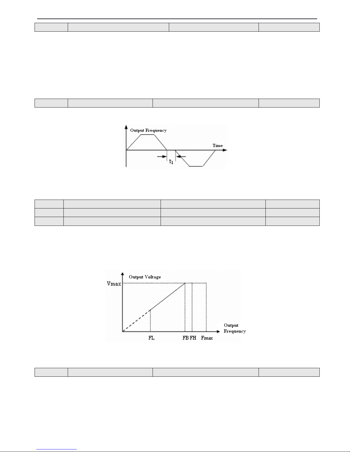
V5 series inverter
55
The unit’s place of this parameter is active with panel control mode to operate jog
.
Unit’s place of LED :
0
0
0
0 : Jog
Jog
Jog
Jog forward
forward
forward
forward in
in
in
in panel
panel
panel
panel control
control
control
control mode
mode
mode
mode
1
1
1
1 : Jog
Jog
Jog
Jog reverse
reverse
reverse
reverse in
in
in
in panel
panel
panel
panel control
control
control
control mode
mode
mode
mode
Ten’s place of LED :
0
0
0
0 : Reverse
Reverse
Reverse
Reverse running
running
running
running is
is
is
is permissible.
permissible.
permissible.
permissible.
1
1
1
1 : Reverse
Reverse
Reverse
Reverse running
running
running
running is
is
is
is prohibit.
prohibit.
prohibit.
prohibit. The inverter will stop output when reverse command is input.
It is the transition time at zero frequency time when the inverter switch ing its running direction, as shown in Fig.4-1 as t
1 .
Fig.
Fig.
Fig.
Fig. 4-1
4-1
4-1
4-1 Run
Run
Run
Run forward/reverse
forward/reverse
forward/reverse
forward/reverse dead
dead
dead
dead time
time
time
time
The max output frequency is the highest permissible frequency of the inverter, as shown in Fig.4-2 .
Basic running frequency is the lowest frequency when the inverter output the highest voltage and it is usually rated
frequency of the motor, as shown in Fig4-2 as
FB
.
The ma x output voltage is the relevant output voltage w hen the inverter output basic running frequency and it is usually
rated voltage of the motor
,
as shown in Fig.4-2 as Vmax.
Fig.
Fig.
Fig.
Fig. 4
4
4
4 -
2
2
2
2
Characteristic
Characteristic
Characteristic
Characteristic parameter
parameter
parameter
parameter
FH,FL are d e fined
by
P0.19 and P0.20 as upper limit of of frequency and lower limit of frequency .
In order to compensate the torque drop at low frequency,the inverter can be boost the output voltage so as to boost the
torque, the torque boost of constant torque c urve and square torque curve are shown in Fig. 4-3 asa,b.
P0.04
P0.04
P0.04
P0.04
Set
Set
Set
Set running
running
running
running direction
direction
direction
direction
Range
Range
Range
Range : 00
00
00
00 ~
11
11
11
11
00
00
00
00
P0.05
P0.05
P0.05
P0.05
Run
Run
Run
Run f
f
f
f orward/
orward/
orward/
orward/ r
r
r
r everse
everse
everse
everse dead
dead
dead
dead time
time
time
time
Range
Range
Range
Range : 0.0
0.0
0.0
0.0 ~ 120.0s
120.0s
120.0s
120.0s
0.1s
0.1s
0.1s
0.1s
P0.06
P0.06
P0.06
P0.06
Max
Max
Max
Max output
output
output
output frequency
frequency
frequency
frequency
Range
Range
Range
Range : 50.00Hz
50.00Hz
50.00Hz
50.00Hz ~ 500
500
500
500 .0Hz
.0Hz
.0Hz
.0Hz
50.00Hz
50.00Hz
50.00Hz
50.00Hz
P0.07
P0.07
P0.07
P0.07
Basic
Basic
Basic
Basic running
running
running
running frequency
frequency
frequency
frequency
Range
Range
Range
Range : 1.00Hz
1.00Hz
1.00Hz
1.00Hz ~ 500.00Hz
500.00Hz
500.00Hz
500.00Hz
50.00Hz
50.00Hz
50.00Hz
50.00Hz
P0.08
P0.08
P0.08
P0.08
Max
Max
Max
Max output
output
output
output voltage
voltage
voltage
voltage
Range
Range
Range
Range : 1
1
1
1 ~ 480V
480V
480V
480V
Rated
Rated
Rated
Rated
P0.09
P0.09
P0.09
P0.09
Torque
Torque
Torque
Torque boost
boost
boost
boost
Range
Range
Range
Range : 0.0
0.0
0.0
0.0 %~ 30.0
30.0
30.0
30.0 %
2.0
2.0
2.0
2.0 %
Page 62
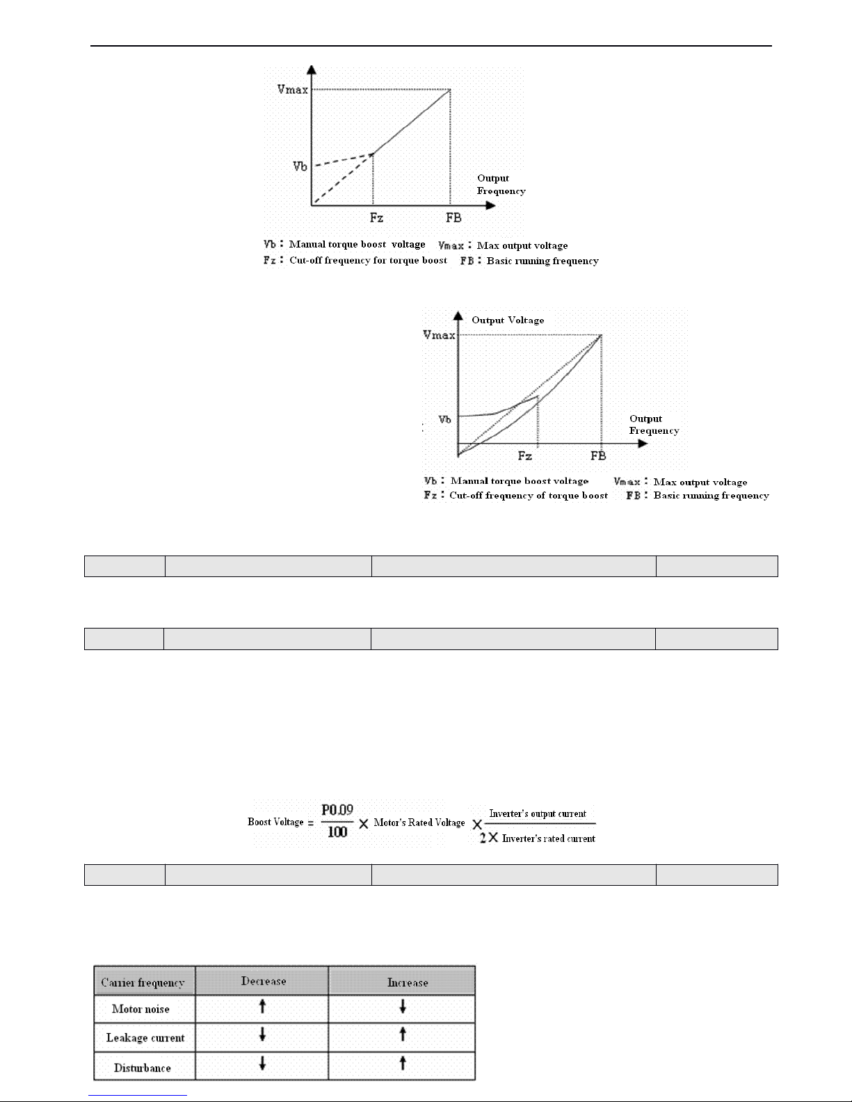
V5 series inverter
56
( a ) Torque boost of constant torque curve
( b ) Torque boost of square torque curve
Fig.
Fig.
Fig.
Fig. 4
4
4
4 — 3
3
3
3 Torque
Torque
Torque
Torque boost
boost
boost
boost
This function define s the cut-off frequency of torque boost, as shown in Fig. 4-3 as Fz. Then cut-off frequency is suitable for
any V/F curve defined
by
P0.02 .
0
0
0
0 : Manual
Manual
Manual
Manual torque
torque
torque
torque boost
boost
boost
boost
Torque boost voltage is defined
by
parameter P0.09. The boost voltage is fixed while motor will be easily magnetism
saturation with light load.
1
1
1
1 : Auto
Auto
Auto
Auto torque
torque
torque
torque boost
boost
boost
boost
Torque boost voltage will change with the motor stator’s current changes. The bigger the stator is,the higher the boost
voltage.
Carrier frequency will effect s the motor’s noise and heat waste.The relationship among carier frequency, motor noise, leak
current, and dist are shown below:
P0.10
P0.10
P0.10
P0.10
Cut-off
Cut-off
Cut-off
Cut-off frequency
frequency
frequency
frequency of
of
of
of torque
torque
torque
torque boost
boost
boost
boost
Range
Range
Range
Range : 0.00Hz
0.00Hz
0.00Hz
0.00Hz ~ Basic
Basic
Basic
Basic running
running
running
running frequency
frequency
frequency
frequency
25.00Hz
25.00Hz
25.00Hz
25.00Hz
P0.11
P0.11
P0.11
P0.11
Torque
Torque
Torque
Torque boost
boost
boost
boost mode
mode
mode
mode
Range
Range
Range
Range : 0
0
0
0 ,
,
,
, 1
1
1
1
0
0
0
0
P0.12
P0.12
P0.12
P0.12
Carrier
Carrier
Carrier
Carrier frequency
frequency
frequency
frequency
Range
Range
Range
Range : 1.0K
1.0K
1.0K
1.0K ~ 14.0K
14.0K
14.0K
14.0K
8.0K
8.0K
8.0K
8.0K
Page 63
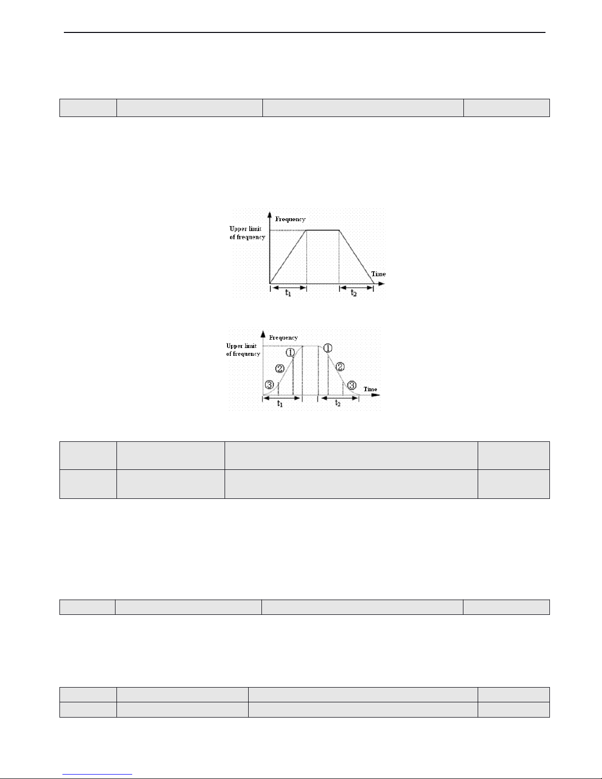
V5 series inverter
57
Note
Note
Note
Note : (1) In order to achieve better performance s,the ratio of carrierfrequency to the maximum running frequency of the
inverter should be less than 36 .
(2) When the carrier frequency is
low,
the current display value may has error.
0
0
0
0 : Linear
Linear
Linear
Linear Acc/Dec
Acc/Dec
Acc/Dec
Acc/Dec mode
mode
mode
mode
Output f requency increases or decreases according to a constant rate ,as shown in Fig. 4-4 .
1
1
1
1 : S
S
S
S ramp
ramp
ramp
ramp Acc/Dec
Acc/Dec
Acc/Dec
Acc/Dec mode
mode
mode
mode
Output frequency increases o r decreases according to a S-shape curve, as shown in Fig.4-5.
Fig.
Fig.
Fig.
Fig. 4-4
4-4
4-4
4-4 Linear
Linear
Linear
Linear Acc/Dec
Acc/Dec
Acc/Dec
Acc/Dec
Fig.
Fig.
Fig.
Fig. 4-5
4-5
4-5
4-5 S
S
S
S -shape
-shape
-shape
-shape curve
curve
curve
curve
P0.14 and P0.15 are only active when Acc/Dcc mode is S ramp Acc/Eec mode ( P0.13 = 1 ) and P0.14+P0.15 <
<
<
< 90 % .
Low speed
time of S rampisshown
in
Fig.4-5 as
③
,
where
the
chang ing
rate
of output
frequency
increasesfor
0.
Linear time of S ramp is shown in Fig.4-5 as ②
,
where the changing rate of output frequency is constant.
High speed time of S ramp is shown in Fig.4-5 as ①
,
where the changing rate of output frequency increases from 0. High
speed time = 100 %- P0.14 - P0.15
.
N
N
N
N ote
ote
ote
ote : S ramp Acc/Dec mode is suitable for the start/stop of elevator, conveying belt, conveying load and so on .
This function defines Acc/Dec time unit
0
0
0
0 : second
second
second
second
1
1
1
1 : minute
minute
minute
minute
Note
Note
Note
Note : (1) This function is active for all the process of Acc/Dec except jog running.
(2) Select second as time unit is recomm ended .
Acc time is the time taken for the motor to accelerate from
0
Hz to upper limit of frequency, as t1in Fig.4-6 ; Dec time is the
time taken for the motor to decelerate from upper limit of frequency to0Hz, as t2in Fig.4-6.
P0.13
P0.13
P0.13
P0.13
Acc/Dec
Acc/Dec
Acc/Dec
Acc/Dec mode
mode
mode
mode
Range
Range
Range
Range : 0
0
0
0 、 1
1
1
1
0
0
0
0
P0.14
P0.14
P0.14
P0.14
L
L
L
L ow
ow
ow
ow speed
speed
speed
speed time
time
time
time of
of
of
of S
S
S
S ramp
ramp
ramp
ramp
Range
Range
Range
Range : 10.0
10.0
10.0
10.0 %~ 50.0
50.0
50.0
50.0 %( Acc/Dec
Acc/Dec
Acc/Dec
Acc/Dec time
time
time
time
) ,
P0.14
P0.14
P0.14
P0.14 + P0.15<90
P0.15<90
P0.15<90
P0.15<90 %
20.0
20.0
20.0
20.0 %
P0.15
P0.15
P0.15
P0.15
Linear
Linear
Linear
Linear time
time
time
time of
of
of
of S
S
S
S ramp
ramp
ramp
ramp
Range
Range
Range
Range : 10.0
10.0
10.0
10.0 %~ 80.0
80.0
80.0
80.0 %( Acc/Dec
Acc/Dec
Acc/Dec
Acc/Dec time
time
time
time
) ,
P0.14
P0.14
P0.14
P0.14 + P0.15<90
P0.15<90
P0.15<90
P0.15<90 %
60.0
60.0
60.0
60.0 %
P0.16
P0.16
P0.16
P0.16
Acc/Dec
Acc/Dec
Acc/Dec
Acc/Dec time
time
time
time unit
unit
unit
unit
Range
Range
Range
Range : 0
0
0
0 ,
,
,
, 1
1
1
1
0
0
0
0
P0.17
P0.17
P0.17
P0.17
Acc
Acc
Acc
Acc time
time
time
time 1
1
1
1
Range
Range
Range
Range : 0.1
0.1
0.1
0.1 ~ 6000.0
6000.0
6000.0
6000.0
10.0
10.0
10.0
10.0
P0.18
P0.18
P0.18
P0.18
Dec
Dec
Dec
Dec time
time
time
time 1
1
1
1
Range
Range
Range
Range : 0.1
0.1
0.1
0.1 ~ 6000.0
6000.0
6000.0
6000.0
10.0
10.0
10.0
10.0
Page 64
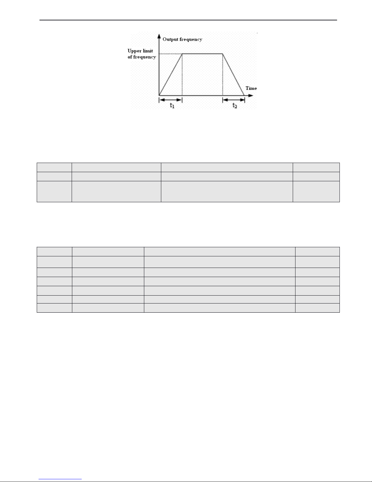
V5 series inverter
58
Fig.
Fig.
Fig.
Fig. 4-6
4-6
4-6
4-6 Acc/Dec
Acc/Dec
Acc/Dec
Acc/Dec time
time
time
time
Note
Note
Note
Note:(1) This series inverter defines seven kinds of Acc/Dec time. Here only defines A cc/Dec time 1,Acc/Dec time 2~7 ar e
defined in P3.14~P3.25.
(2) M inute and second as the time unit of Acc/Dec time 1~7 can be selected via P0.09 and the default unit is second.
P0.19 and P0.20 define the upper and lower frequency of frequencies respectively,as shown in Fig.4-2 as FH and FL.
When the actual frequency is lower than the lower limit of frequency, inverter will accelerate with the accelerate time which
you have set, and then after reaching the lower limit of frequency, inverter will running with the lower limit of frequency if the
running mode is0and it will de celerate output frequency continuously until 0Hz with the running mode is 1.
This group of parameters define s the flex ible V/F setting modes of this inverter to satisfy the requirement of different loads.
Four fixed curve s and one user-define
d
curve can be selected according to P0.22 .
P0.22=0 , V/F curve is constant torque curve,as shown in Fig.4-7 as curve0.
P0.22=1 , V/F cuve is 1.2 order torque-reducing curve ,
as
shown
in
Fig.
4 -7as
curve
1 .
P0.22=2 , V/F cuve is 1.
7
order torque-reducing curve , as shown in Fig.4-7 as curve 2.
P0.22=3 , V/F cuve is 2.0 order torque-reducing curve , as shown in Fig.4-7 as curve 3.
To
achieve best energy-saving effect, you can select 1,2 or 3 V/F curve s according to the actual loads such as fans and
pump s .
P0.19
P0.19
P0.19
P0.19
Upper
Upper
Upper
Upper limit
limit
limit
limit o
o
o
o f
f
f
f frequency
frequency
frequency
frequency
Range
Range
Range
Range : lower
lower
lower
lower limit
limit
limit
limit of
of
of
of frequency
frequency
frequency
frequency ~ max
max
max
max output
output
output
output frequency
frequency
frequency
frequency
50.00Hz
50.00Hz
50.00Hz
50.00Hz
P0.20
P0.20
P0.20
P0.20
Lower
Lower
Lower
Lower limit
limit
limit
limit of
of
of
of frequency
frequency
frequency
frequency
Range
Range
Range
Range : 0.00Hz
0.00Hz
0.00Hz
0.00Hz ~ upper
upper
upper
upper limit
limit
limit
limit of
of
of
of frequency
frequency
frequency
frequency
0.00HZ
0.00HZ
0.00HZ
0.00HZ
P0.21
P0.21
P0.21
P0.21
Lower
Lower
Lower
Lower mimit
mimit
mimit
mimit of
of
of
of frequency
frequency
frequency
frequency mode
mode
mode
mode
Range
Range
Range
Range :
0
0
0
0 : running
running
running
running with
with
with
with lower
lower
lower
lower limit
limit
limit
limit of
of
of
of frequency
frequency
frequency
frequency
1
1
1
1 : stop
stop
stop
stop
0
0
0
0
P0.22
P0.22
P0.22
P0.22
V/F
V/F
V/F
V/F curve
curve
curve
curve setting
setting
setting
setting
Range
Range
Range
Range : 0
0
0
0 ~ 4
4
4
4
0
0
0
0
P0.23
P0.23
P0.23
P0.23
V/F
V/F
V/F
V/F frequency
frequency
frequency
frequency value
value
value
value F1
F1
F1
F1
Range
Range
Range
Range : 0.00
0.00
0.00
0.00 ~ P0.25
P0.25
P0.25
P0.25
0.00Hz
0.00Hz
0.00Hz
0.00Hz
P0.24
P0.24
P0.24
P0.24
V/F
V/F
V/F
V/F voltage
voltage
voltage
voltage value
value
value
value V1
V1
V1
V1
Range
Range
Range
Range : 0
0
0
0 ~ P0.26
P0.26
P0.26
P0.26
0.0
0.0
0.0
0.0 %
P0.25
P0.25
P0.25
P0.25
V/F
V/F
V/F
V/F frequency
frequency
frequency
frequency value
value
value
value F2
F2
F2
F2
Range
Range
Range
Range : P0.23
P0.23
P0.23
P0.23 ~ P0.27
P0.27
P0.27
P0.27
0.00Hz
0.00Hz
0.00Hz
0.00Hz
P0.26
P0.26
P0.26
P0.26
V/F
V/F
V/F
V/F voltage
voltage
voltage
voltage value
value
value
value V2
V2
V2
V2
Range
Range
Range
Range : P0.24
P0.24
P0.24
P0.24 ~ P0.28
P0.28
P0.28
P0.28
0.0
0.0
0.0
0.0 %
P0.27
P0.27
P0.27
P0.27
V/F
V/F
V/F
V/F frequency
frequency
frequency
frequency value
value
value
value F3
F3
F3
F3
Range
Range
Range
Range : P0.25
P0.25
P0.25
P0.25 ~ P0.07
P0.07
P0.07
P0.07 basic
basic
basic
basic running
running
running
running frequency
frequency
frequency
frequency
0.00Hz
0.00Hz
0.00Hz
0.00Hz
P0.28
P0.28
P0.28
P0.28
V/F
V/F
V/F
V/F voltage
voltage
voltage
voltage value
value
value
value V3
V3
V3
V3
Range
Range
Range
Range : P0.26
P0.26
P0.26
P0.26 ~ 100.0
100.0
100.0
100.0 %
0.0
0.0
0.0
0.0 %
Page 65
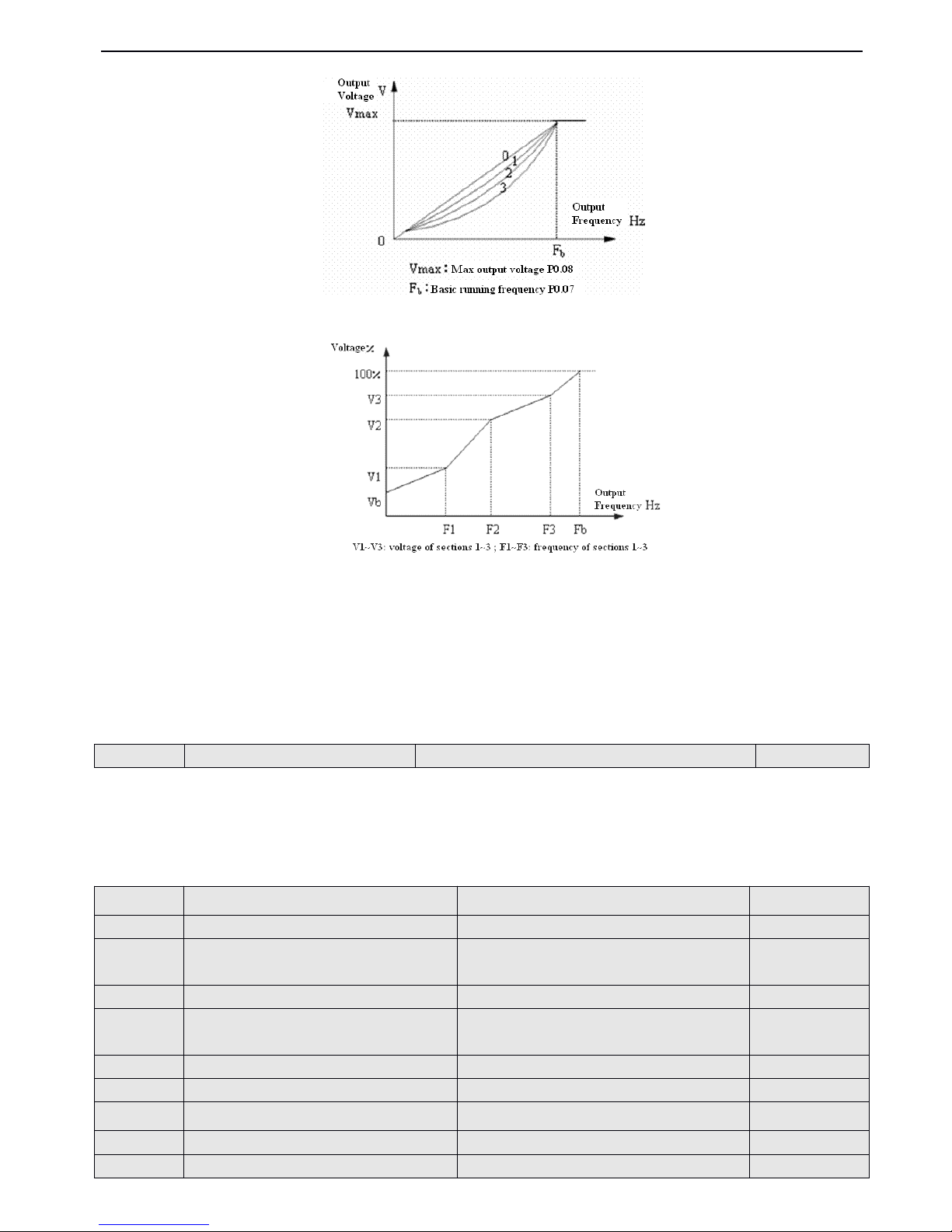
V5 series inverter
59
Fig.
Fig.
Fig.
Fig. 4
4
4
4 -
-
-
- 7
7
7
7 V/F
V/F
V/F
V/F curve
curve
curve
curve
Fig.
Fig.
Fig.
Fig. 4
4
4
4 -
-
-
- 8
8
8
8 U
U
U
U ser-defined
ser-defined
ser-defined
ser-defined V/F
V/F
V/F
V/F curve
curve
curve
curve
When P0.22 is set to 4 , you can define V/ F curve via modifying (V1 , F1)
,
(V2 , F2)
,
(V3 , F3) to satisfy the special load
requirement,as shown in Fig.4-8.Torque boost is suitable for user-defined V/F curve.In Fig.4-8
.
Vb = Torque boost ( P0.09 ) × V1
4-2-2
4-2-2
4-2-2
4-2-2
.
.
.
.
Parameters
Parameters
Parameters
Parameters of
of
of
of reference
reference
reference
reference frequency
frequency
frequency
frequency ( Group
Group
Group
Group P1
P1
P1
P1 )
It is the constant time of the filter that is for internal sample picking
by
inverter when reference frequency is setbyexternal
analog channel.When the wire is too long or the interference is serious which can lead to reference frequency becomes
wavy, you can increase filter time to improve the situation. The bigger the time constant is,the higher the immunity level,
but the response time is prolonged with the increase of the time constant. That is, the smaller the time constant is, the shorter
the response time, but the lower the immunity level.
P1.00
P1.00
P1.00
P1.00
Time
Time
Time
Time constant
constant
constant
constant of
of
of
of analog
analog
analog
analog filter
filter
filter
filter
Range
Range
Range
Range : 0.01
0.01
0.01
0.01 ~ 30.00s
30.00s
30.00s
30.00s
0.20s
0.20s
0.20s
0.20s
P1.01
P1.01
P1.01
P1.01
Gain
Gain
Gain
Gain of
of
of
of reference
reference
reference
reference frequency
frequency
frequency
frequency selector
selector
selector
selector of
of
of
of VI
VI
VI
VI
Range
Range
Range
Range : 0.01
0.01
0.01
0.01 ~ 9.99
9.99
9.99
9.99
1.00
1.00
1.00
1.00
P1.02
P1.02
P1.02
P1.02
Min
Min
Min
Min reference
reference
reference
reference of
of
of
of VI
VI
VI
VI
Range
Range
Range
Range : 0.00
0.00
0.00
0.00 ~ P1.04
P1.04
P1.04
P1.04
0.00V
0.00V
0.00V
0.00V
P1.03
P1.03
P1.03
P1.03
Frequency
Frequency
Frequency
Frequency corresponding
corresponding
corresponding
corresponding to
to
to
to min
min
min
min reference
reference
reference
reference of
of
of
of
VI
VI
VI
VI
Range
Range
Range
Range : 0.00
0.00
0.00
0.00 ~ upper
upper
upper
upper limit
limit
limit
limit of
of
of
of frequency
frequency
frequency
frequency
0.00Hz
0.00Hz
0.00Hz
0.00Hz
P1.04
P1.04
P1.04
P1.04
Max
Max
Max
Max reference
reference
reference
reference of
of
of
of VI
VI
VI
VI
Range
Range
Range
Range : P1.04
P1.04
P1.04
P1.04 ~ 10.00V
10.00V
10.00V
10.00V
10.00V
10.00V
10.00V
10.00V
P1.05
P1.05
P1.05
P1.05
Frequency
Frequency
Frequency
Frequency corresponding
corresponding
corresponding
corresponding to
to
to
to max
max
max
max reference
reference
reference
reference of
of
of
of
VI
VI
VI
VI
Range
Range
Range
Range : 0.00
0.00
0.00
0.00 ~ upper
upper
upper
upper limit
limit
limit
limit of
of
of
of frequency
frequency
frequency
frequency
50.00Hz
50.00Hz
50.00Hz
50.00Hz
P1.06
P1.06
P1.06
P1.06
Gain
Gain
Gain
Gain of
of
of
of reference
reference
reference
reference frequency
frequency
frequency
frequency selector
selector
selector
selector of
of
of
of CI
CI
CI
CI
Range
Range
Range
Range : 0.01
0.01
0.01
0.01 ~ 9.99
9.99
9.99
9.99
1.00
1.00
1.00
1.00
P1.07
P1.07
P1.07
P1.07
Min
Min
Min
Min reference
reference
reference
reference of
of
of
of CI
CI
CI
CI
Range
Range
Range
Range : 0.00
0.00
0.00
0.00 ~ P1.09
P1.09
P1.09
P1.09
0.00V
0.00V
0.00V
0.00V
P1.08
P1.08
P1.08
P1.08
Frequency
Frequency
Frequency
Frequency according
according
according
according to
to
to
to mi
mi
mi
mi n
n
n
n reference
reference
reference
reference of
of
of
of CI
CI
CI
CI
Range
Range
Range
Range : 0.00
0.00
0.00
0.00 ~ upper
upper
upper
upper limit
limit
limit
limit of
of
of
of frequency
frequency
frequency
frequency
0.00Hz
0.00Hz
0.00Hz
0.00Hz
P1.09
P1.09
P1.09
P1.09
Max
Max
Max
Max frequency
frequency
frequency
frequency of
of
of
of CI
CI
CI
CI
Range
Range
Range
Range : P1.07
P1.07
P1.07
P1.07 ~ 10.00V
10.00V
10.00V
10.00V
10.00V
10.00V
10.00V
10.00V
P1.10
P1.10
P1.10
P1.10
Frequency
Frequency
Frequency
Frequency according
according
according
according to
to
to
to max
max
max
max reference
reference
reference
reference of
of
of
of CI
CI
CI
CI
Range
Range
Range
Range : 0.00
0.00
0.00
0.00 ~ upper
upper
upper
upper limit
limit
limit
limit of
of
of
of frequency
frequency
frequency
frequency
50.00Hz
50.00Hz
50.00Hz
50.00Hz
Page 66
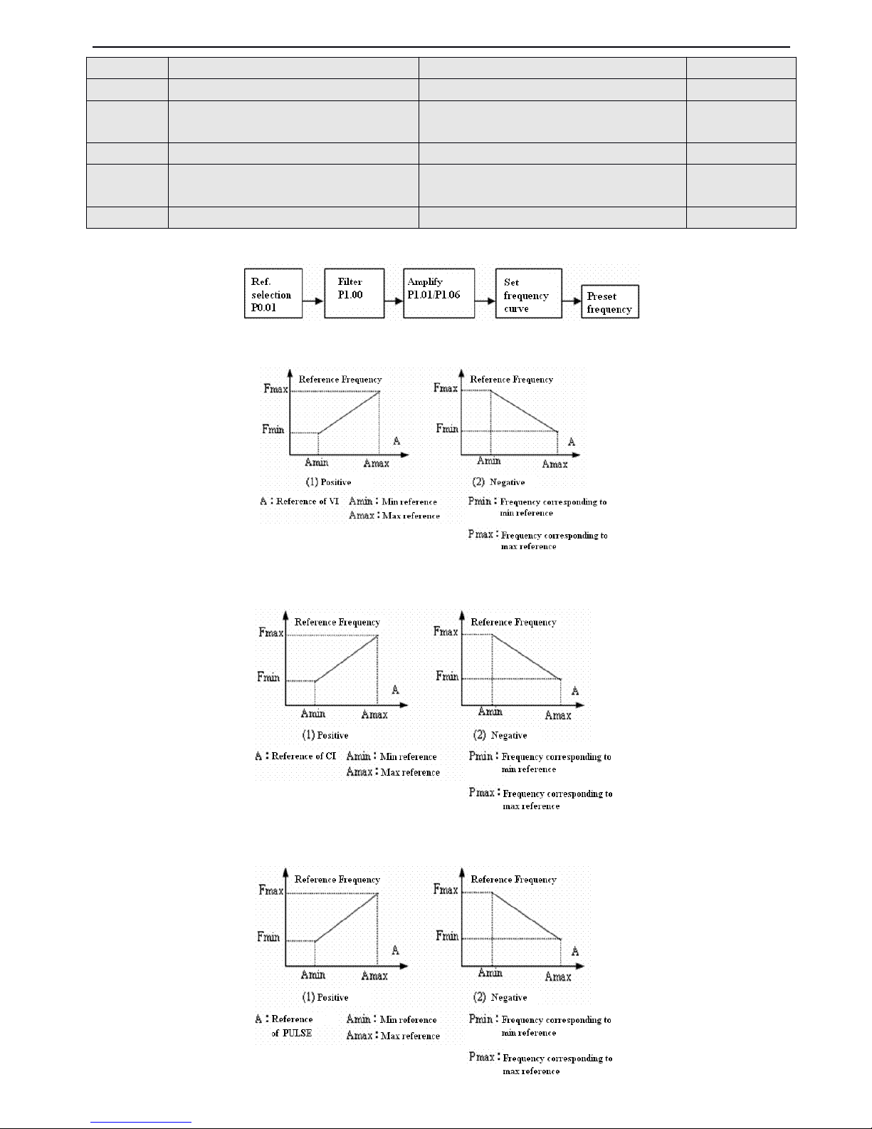
V5 series inverter
60
When VI, CI and PULSE are selected, the relationship between reference and the present frequency is shown below:
The relationship between VI and preset frequency is shown below:
The
The
The
The relationship
relationship
relationship
relationship between
between
between
between CI
CI
CI
CI and
and
and
and reference
reference
reference
reference frequency
frequency
frequency
frequency is
is
is
is shown
shown
shown
shown below:
below:
below:
below:
The
The
The
The relationship
relationship
relationship
relationship between
between
between
between PULSE
PULSE
PULSE
PULSE and
and
and
and reference
reference
reference
reference frequency
frequency
frequency
frequency is
is
is
is shown
shown
shown
shown below:
below:
below:
below:
P1.11
P1.11
P1.11
P1.11
Max
Max
Max
Max input
input
input
input pulse
pulse
pulse
pulse frequency
frequency
frequency
frequency of
of
of
of PULSE
PULSE
PULSE
PULSE
Range
Range
Range
Range : 0.1
0.1
0.1
0.1 ~ 20.0K
20.0K
20.0K
20.0K
10.0K
10.0K
10.0K
10.0K
P1.12
P1.12
P1.12
P1.12
Min
Min
Min
Min reference
reference
reference
reference of
of
of
of PULSE
PULSE
PULSE
PULSE
Range
Range
Range
Range : 0.0
0.0
0.0
0.0 ~ P1.14
P1.14
P1.14
P1.14
0.1K
0.1K
0.1K
0.1K
P1.13
P1.13
P1.13
P1.13
Frequency
Frequency
Frequency
Frequency corresponding
corresponding
corresponding
corresponding to
to
to
to min
min
min
min reference
reference
reference
reference of
of
of
of
PULSE
PULSE
PULSE
PULSE
Range
Range
Range
Range : 0.00
0.00
0.00
0.00 ~ upper
upper
upper
upper limit
limit
limit
limit of
of
of
of frequency
frequency
frequency
frequency
0.00Hz
0.00Hz
0.00Hz
0.00Hz
P1.14
P1.14
P1.14
P1.14
Max
Max
Max
Max reference
reference
reference
reference of
of
of
of PULSE
PULSE
PULSE
PULSE
Range
Range
Range
Range : P1.12
P1.12
P1.12
P1.12 ~ P1.11
P1.11
P1.11
P1.11
10.0K
10.0K
10.0K
10.0K
P1.15
P1.15
P1.15
P1.15
Frequency
Frequency
Frequency
Frequency corresponding
corresponding
corresponding
corresponding to
to
to
to max
max
max
max reference
reference
reference
reference of
of
of
of
PULSE
PULSE
PULSE
PULSE
Range
Range
Range
Range : 0
0
0
0 .00
.00
.00
.00 ~ upper
upper
upper
upper limit
limit
limit
limit of
of
of
of frequency
frequency
frequency
frequency
50.00Hz
50.00Hz
50.00Hz
50.00Hz
P1.16
P1.16
P1.16
P1.16
Input
Input
Input
Input mode
mode
mode
mode of
of
of
of CI
CI
CI
CI
Range
Range
Range
Range : 0
0
0
0 、 1
1
1
1
0
0
0
0
Page 67
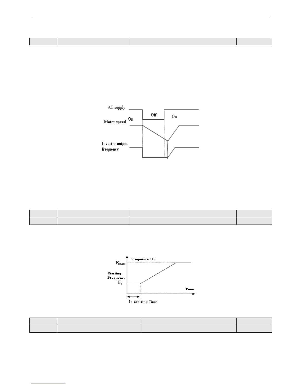
V5 series inverter
61
4-2-3
4-2-3
4-2-3
4-2-3
.
.
.
.
Starting
Starting
Starting
Starting and
and
and
and braking
braking
braking
braking parameters
parameters
parameters
parameters ( Group
Group
Group
Group P2
P2
P2
P2 )
0
0
0
0 : Start
Start
Start
Start from
from
from
from the
the
the
the starting
starting
starting
starting frequency
frequency
frequency
frequency
Inverter starts at the start ing frequency (P2.01) within the holding time of starting frequency ( P2.02
)
.
1
1
1
1 : Brake
Brake
Brake
Brake first
first
first
first and
and
and
and then
then
then
then start
start
start
start
Brake with DC braking current (P2.03 ) within braking time
(P2
.04) and then start at starting frequency .
2
2
2
2 : Start
Start
Start
Start on
on
on
on the
the
the
the fly
fly
fly
fly
When P2.00 is set to2,
it is suitable for repower ing after instantaneous power off or re start ing after external fault. As shown
in Fig.4-9.
Fig.
Fig.
Fig.
Fig. 4-9
4-9
4-9
4-9 Start
Start
Start
Start on
on
on
on the
the
the
the fly
fly
fly
fly
Note
Note
Note
Note : (1) S tarting mode 0 : It is recommended in general application or when the inverter drives s ynchromous motor .
(2) Starting mode 1: It is suitable for starting the motor that is running in forward or reverse with small inertial load,
and it is not recommended for big inertial load .
(3) Starting mode 2: It is suitable for starting the motor that is in free stop or for restart ing after instant ane ous power
off.
Starting frequency point s to the initial frequency when inverter starts, as shown in Fig.4-10 as Fs. Holding time of starting
frequency points to the holding time while inverter is running at the starting frequency,as shown in Fig.4-10 as t
1 .
Note
Note
Note
Note : Starting frequency is not stricted
by
the lower limit of frequency
Fig.
Fig.
Fig.
Fig. 4-10
4-10
4-10
4-10 Starting
Starting
Starting
Starting frequency
frequency
frequency
frequency and
and
and
and starting
starting
starting
starting time
time
time
time
When P2.00 is set to 1 , P2.03 and P2.04 are active , as shown in Fig. 4-11
P2.00
P2.00
P2.00
P2.00
Starting
Starting
Starting
Starting mode
mode
mode
mode
Range
Range
Range
Range : 0
0
0
0 ,
,
,
, 1
1
1
1 ,
,
,
, 2
2
2
2
0
0
0
0
P2.01
P2.01
P2.01
P2.01
Start
Start
Start
Start ing
ing
ing
ing frequency
frequency
frequency
frequency
Range
Range
Range
Range : 0.20
0.20
0.20
0.20 ~ 20.00Hz
20.00Hz
20.00Hz
20.00Hz
0.50
0.50
0.50
0.50 Hz
Hz
Hz
Hz
P2.02
P2.02
P2.02
P2.02
Holding
Holding
Holding
Holding time
time
time
time of
of
of
of starting
starting
starting
starting frequency
frequency
frequency
frequency
Range
Range
Range
Range : 0.0
0.0
0.0
0.0 ~ 30.0S
30.0S
30.0S
30.0S
0.0S
0.0S
0.0S
0.0S
P2.03
P2.03
P2.03
P2.03
DC
DC
DC
DC injection
injection
injection
injection braking
braking
braking
braking current
current
current
current at
at
at
at start
start
start
start
Range
Range
Range
Range : 0
0
0
0 ~ 80(
80(
80(
80( % )
)
)
)
0(
0(
0(
0( % )
)
)
)
P2.04
P2.04
P2.04
P2.04
DC
DC
DC
DC injection
injection
injection
injection braking
braking
braking
braking time
time
time
time at
at
at
at start
start
start
start
Range
Range
Range
Range : 0.0
0.0
0.0
0.0 ~ 60.0S
60.0S
60.0S
60.0S
0.0S
0.0S
0.0S
0.0S
Page 68
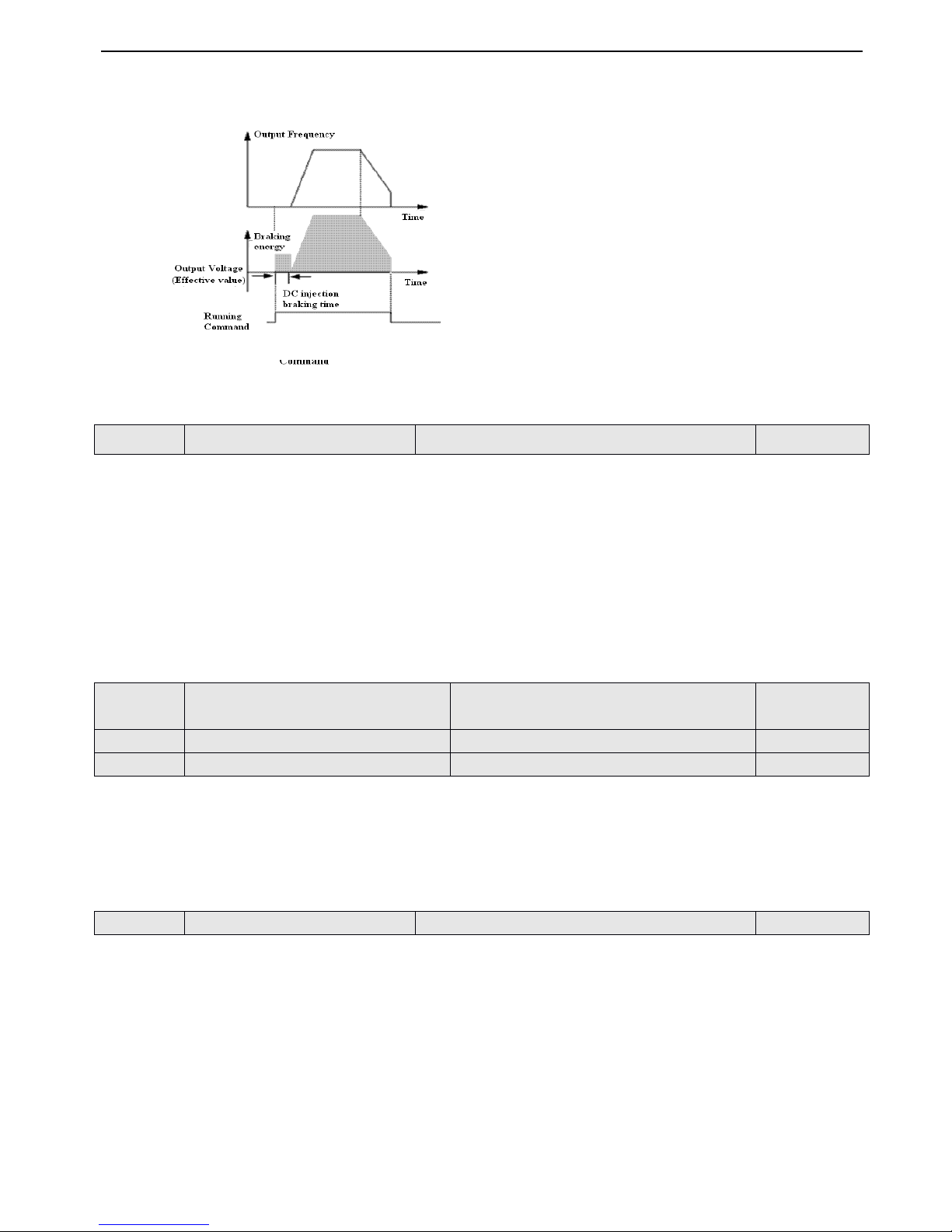
V5 series inverter
62
DC injection braking current at start is a percentage value of inverter’s rated current. There is no DC injection braking when
the braking time is 0.00s.
Fig.
Fig.
Fig.
Fig. 4-11
4-11
4-11
4-11 Starting
Starting
Starting
Starting mode
mode
mode
mode 1
1
1
1
Fig.
Fig.
Fig.
Fig. 4-12
4-12
4-12
4-12 Dec-to-stop
Dec-to-stop
Dec-to-stop
Dec-to-stop +
+
+
+ DC
DC
DC
DC injection
injection
injection
injection braking
braking
braking
braking
0
0
0
0 : Dec-to-stop
Dec-to-stop
Dec-to-stop
Dec-to-stop
After rece i ving the stopping command, the inverter reduces its output frequency within its Dec time and stops when the
frequency becomes0.
1
1
1
1 : Coast
Coast
Coast
Coast
to
to
to
to
stop
stop
stop
stop
After receiving the stopping command, the inverter stops output power immediately and the motor stops according to
mechanical inertia.
2
2
2
2 : Dec-to-stop
Dec-to-stop
Dec-to-stop
Dec-to-stop + DC
DC
DC
DC injection
injection
injection
injection braking
braking
braking
braking
After receiving the stopping command, the inverter reduces its output frequency according to Dec time and then start to DC
injection braking after the output frequency reaching the initial frequency of braking at stop as i n P2.06 .
P2.08 refers to the set of DC injection braking current at stop which is the percentage value of inverter’s rated current .There
is no DC injection braking when the braking time is 0.0, as shown in Fig.4-12 .
4-2-4
4-2-4
4-2-4
4-2-4
.
.
.
.
Auxiliary
Auxiliary
Auxiliary
Auxiliary running
running
running
running parameters
parameters
parameters
parameters ( Group
Group
Group
Group P3
P3
P3
P3 )
When P0.01 ( Frequency setting mode ) is set to 8 , combination of frequency setting can be set through this parameter.
0 : VI + CI
1 : VI - CI
2 : External pulse reference + VI + Increase/Decrease key reference
3 : External pulse reference - VI - Increase/Decrease key reference
4 : External pulse reference + CI
5 : External pulse reference - CI
6 : RS485 + VI + Increase/Decrease key reference
7 : RS485 - VI - Increase/Decrease key reference
8 : RS485 + CI + Increase/Decrease key reference
P2.05
P2.05
P2.05
P2.05
Stopping
Stopping
Stopping
Stopping mode
mode
mode
mode
Range
Range
Range
Range : 0
0
0
0 ,
,
,
, 1
1
1
1 ,
,
,
, 2
2
2
2
0
0
0
0
P2.06
P2.06
P2.06
P2.06
DC
DC
DC
DC injection
injection
injection
injection braking
braking
braking
braking initial
initial
initial
initial frequency
frequency
frequency
frequency at
at
at
at
stop
stop
stop
stop
Range
Range
Range
Range : 0.0
0.0
0.0
0.0 ~ 15.00Hz
15.00Hz
15.00Hz
15.00Hz
3.00Hz
3.00Hz
3.00Hz
3.00Hz
P2.07
P2.07
P2.07
P2.07
DC
DC
DC
DC injection
injection
injection
injection braking
braking
braking
braking time
time
time
time at
at
at
at stop
stop
stop
stop
Range
Range
Range
Range : 0.0
0.0
0.0
0.0 ~ 60.0S
60.0S
60.0S
60.0S
0.0S
0.0S
0.0S
0.0S
P2.08
P2.08
P2.08
P2.08
injection
injection
injection
injection braking
braking
braking
braking current
current
current
current at
at
at
at stop
stop
stop
stop
Range
Range
Range
Range : 0
0
0
0 ~ 80
80
80
80 (%)
0(
0(
0(
0( % )
)
)
)
P3.00
P3.00
P3.00
P3.00
Combination
Combination
Combination
Combination of
of
of
of frequency
frequency
frequency
frequency setting
setting
setting
setting
Range
Range
Range
Range : 0
0
0
0 ~ 20
20
20
20
0
0
0
0
Page 69
V5 series inverter
63
9 : RS485 - CI - Increase/Decrease key reference
10 : RS485 + CI + External pulse reference
11 : RS485 - CI - External pulse reference
12 : RS485 + VI + External pulse reference
13 : RS485 - VI - External pulse reference
14 : VI + CI + Increase/Decrease key reference + Digital setting P 0.02
15 : VI + CI - Increase/Decrease key reference + Digital setting P 0.02
16 : MAX ( VI , CI )
17 : MIN ( VI , CI )
18 : MAX ( VI , CI , P LU SE )
19 : MIN ( VI , CI , P LU SE )
20 : VI , CI is active , VI is priority
LED
LED
LED
LED unit
unit
unit
unit
’
’
’
’
s
s
s
s place
place
place
place
0 : A ll the parameters are allowed modifying.
1 : Only P3.01 can be modified.
2 : Only P0.02 and P3.01 can be modified.
LED
LED
LED
LED ten
ten
ten
ten
’
’
’
’
s
s
s
s place
place
place
place
0 : Disable d
1 : Re store to factory setting
2 : Clear fault record
Note
Note
Note
Note : (1) The factory setting of P3.01 is0and allow all the parameters to be modified. After modifying this parameter,
please set it as0i f you want to modify other parameter s .Also ,you can set protective grade.
(2) P3.01 will be changed to0au tomatically after restor ing to factory setting
.
0
0
0
0 : Disabled
Disabled
Disabled
Disabled
1
1
1
1 : Parameter
Parameter
Parameter
Parameter up
up
up
up load
load
load
load : Up load the parameters from inverter to remote opration panel.
2
2
2
2 : Parameter
Parameter
Parameter
Parameter down
down
down
down load
load
load
load : Down load the parameters from remote operation panel to inverter.
Note
Note
Note
Note : This
This
This
This function
function
function
function is
is
is
is still
still
still
still in
in
in
in devel
devel
devel
devel op
op
op
op
ing
ing
ing
ing
.
.
.
.
0
0
0
0 : Disabled
Disabled
Disabled
Disabled
1
1
1
1 : Enabled
Enabled
Enabled
Enabled
Inverter can regulate output voltage through detect ing load current to achieve energy-saving when the motor running
without load or with light load.Au to energy-saving is suitable for the application with steadyload and speed.
AVR
function points to regulat ing voltage automa tically .When the input voltage of inverter fluctuate s,
AVR
function can
keep it steady.
In Dec-to-stop process,if
AVR
is disabled, the Dec time is short and the running current is big ; if
AVR
is enabled, the motor
decelerates steadily,the running current is small and the Dec time is prolonged .
0
0
0
0 : Disabled
Disabled
Disabled
Disabled
1
1
1
1 : Enabled
Enabled
Enabled
Enabled
2
2
2
2 : Disabled
Disabled
Disabled
Disabled in
in
in
in Dec
Dec
Dec
Dec process
process
process
process
This function can make suitable regulation for inverter’s output frequency according to the load changes,and control the
P3.01
P3.01
P3.01
P3.01
Parameter
Parameter
Parameter
Parameter initialization
initialization
initialization
initialization
locking
locking
locking
locking up
up
up
up
Range
Range
Range
Range : LED
LED
LED
LED unit
unit
unit
unit
’
’
’
’
s
s
s
s place
place
place
place 0~2
0~2
0~2
0~2 ,
LED
LED
LED
LED ten
ten
ten
ten
’
’
’
’
s
s
s
s place
place
place
place 0~2
0~2
0~2
0~2
00
00
00
00
P3.02
P3.02
P3.02
P3.02
Parameter
Parameter
Parameter
Parameter copy
copy
copy
copy
Range
Range
Range
Range : 0
0
0
0 ,
,
,
, 1
1
1
1 ,
,
,
, 2
2
2
2
0
0
0
0
P3.03
P3.03
P3.03
P3.03
Auto
Auto
Auto
Auto energy-saving
energy-saving
energy-saving
energy-saving function
function
function
function
Range
Range
Range
Range : 0
0
0
0 ,
,
,
, 1
1
1
1
0
0
0
0
P3.04
P3.04
P3.04
P3.04
AVR
AVR
AVR
AVR
funciton
funciton
funciton
funciton
Range
Range
Range
Range : 0
0
0
0 ,
,
,
, 1
1
1
1 ,
,
,
, 2
2
2
2
0
0
0
0
P3.05
P3.05
P3.05
P3.05
Gain
Gain
Gain
Gain of
of
of
of slip
slip
slip
slip compensation
compensation
compensation
compensation
Range
Range
Range
Range : 0
0
0
0 ~ 150(
150(
150(
150( % )
)
)
)
0(
0(
0(
0( % )
)
)
)
Page 70
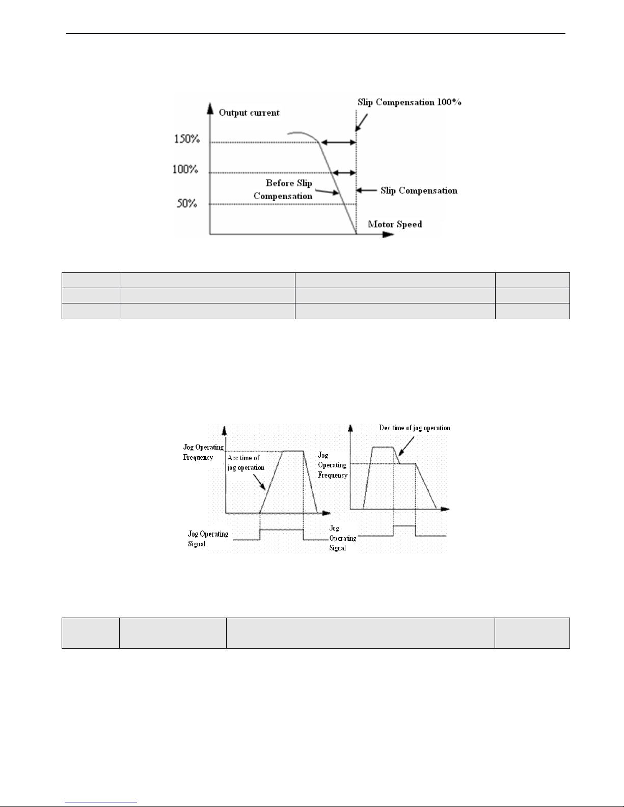
V5 series inverter
64
speed at a certain value wit h dynamic compensation for slip frequency of asy nchronism motor. I f use auto-torque boost
function in add ition, better low speed moment c haracteristic can be get. As shown in Fig.4-13.
Fig.
Fig.
Fig.
Fig. 4-13
4-13
4-13
4-13 Slip
Slip
Slip
Slip Compensation
Compensation
Compensation
Compensation
Jog operating frequency has the highest priority.No matter what statu s the inverter is in, once there is a jog operating
command input, the inverter will run into jog operating frequency w ithin Acc/Dec time of jog operation, as shown in Fig.4-
14.
Acc time of jog operation means the time needed for inverter from
0
Hz to upper limit of frequency, Dec time of jog
operation means the time needed for inverter from upper limit of frequency to0Hz.
Fig
Fig
Fig
Fig 4-14
4-14
4-14
4-14 Jog
Jog
Jog
Jog operation
operation
operation
operation
Note
Note
Note
Note :
:
:
: (1) Jog operation can be controlled
by
panel, terminal and serial port .
(2) If jog operation command has been canceled, the inverter will stop according to Dec-to-time.
You
can change baud rate, digital format and communication mode
by
setting unit’s place, ten’s place and hundred’s place
of P3.09 .
Unit
Unit
Unit
Unit
’
’
’
’
s
s
s
s place
place
place
place of
of
of
of LED
LED
LED
LED : Set baud rate,the value s are shown below:
0 : 1200BPS
1 : 2400BPS
2 : 4800BPS
3 : 9600BPS
4 : 19200BPS
P3.06
P3.06
P3.06
P3.06
Jog
Jog
Jog
Jog operating
operating
operating
operating frequency
frequency
frequency
frequency
Range
Range
Range
Range : 0.10
0.10
0.10
0.10 ~ 50.00Hz
50.00Hz
50.00Hz
50.00Hz
5.00Hz
5.00Hz
5.00Hz
5.00Hz
P3.07
P3.07
P3.07
P3.07
Acc
Acc
Acc
Acc time
time
time
time of
of
of
of jog
jog
jog
jog operation
operation
operation
operation
Range
Range
Range
Range : 0.1
0.1
0.1
0.1 ~ 60.0S
60.0S
60.0S
60.0S
5.0S
5.0S
5.0S
5.0S
P3.08
P3.08
P3.08
P3.08
Dec
Dec
Dec
Dec time
time
time
time of
of
of
of jog
jog
jog
jog operation
operation
operation
operation
Range
Range
Range
Range : 0.1
0.1
0.1
0.1 ~ 60.0S
60.0S
60.0S
60.0S
5.0S
5.0S
5.0S
5.0S
P3.09
P3.09
P3.09
P3.09
Communication
Communication
Communication
Communication
conf
conf
conf
conf iguration
iguration
iguration
iguration
Range
Range
Range
Range : 000
000
000
000 ~ 155
155
155
155
054
054
054
054
Page 71
V5 series inverter
65
5 : 38400BPS
Ten
Ten
Ten
Ten
’
’
’
’
s
s
s
s place
place
place
place of
of
of
of LED
LED
LED
LED : Set digital format, the values are show below:
0 : 1 - 7 - 2 format , no parity check ;
1
stop bit ,
7
data bits , 2 stop bits , no parity check.
1 : 1 - 7 -
1
format , odd ;
1
stop bit ,
7
data bits ,
1
stop bits , odd
2 : 1 - 7 -
1
format , even ; 1 stop bit ,
7
data bits ,
1
stop bit , even
3 : 1 - 8 - 2 format , no parity check ;
1
stop bit ,
8
data bits , 2 stop bits , no parity check .
4 : 1 - 8 -
1
format , odd ;
1
stop bit ,
8
data bits ,
1
stop bit,odd
5 : 1 - 8 -
1
format , even ; 1 stop bit ,
8
data bits ,
1
stop bit , even
6 : 1 - 8 -
1
format , no parity check ;
1
stop bit ,
8
data bits ,
1
stop bit , no parity check
.
Hundred
Hundred
Hundred
Hundred
’
’
’
’
s
s
s
s place
place
place
place of
of
of
of LED
LED
LED
LED : undefined
Note
Note
Note
Note : when choose Modbus-RTU communication mode , you should select digital format 3~6 .
This parameter is used for identify the inverter’s address in serial communication.
0
is the broadcast address.If take inverter as a slave, it will receive the command with
0
as broadcast address and will not
answer the PC.
248 is the address with inverter as a host.If take inverter as host and set P3.10 as 248 , it can send broadcast command to
other inverters to realize mu l ti- machine
.
When serial port failed and the duration over the reference value
,
the inverter will judge it as communication fault.
When set the value as 0, the inverter will not detect the serial communication port and this function disabled.
It refers to time from inverter’s serial port receiv ing and execu ting the command of host PC to returning response to it.
This parameter is used for set ting the proportion coefficient according to frequen
cy
setting command which is receiving
by
inverter through RS485, the actual running frequency equivalent to this parameter mu l tiply the frequency value receiving
through RS485.
This parameter can also set running frequency proportion of several inverters in multimachine linkage mode.
Seven
kinds
of
Acc/Dec
time
can
be
defined,
and
the
inverter’s
Acc/Dec
time
1~7 can
be
selected
by
different
combination of
control
terminals.
Please
refertothe
introductions of P4.00~P4.05
for the definitions
of terminals
used
to
select Acc/Dec time,
also, you
can refertoAcc/Dec
time
defined
in
P0.17
and
P0.18.
P3.10
P3.10
P3.10
P3.10
Local
Local
Local
Local address
address
address
address
Range
Range
Range
Range : 0
0
0
0 ~ 248
248
248
248
1
1
1
1
P3.11
P3.11
P3.11
P3.11
Time
Time
Time
Time threshod
threshod
threshod
threshod for
for
for
for judging
judging
judging
judging
communication
communication
communication
communication status
status
status
status
Range
Range
Range
Range : 0.0
0.0
0.0
0.0 ~ 1000.0S
1000.0S
1000.0S
1000.0S
0.0S
0.0S
0.0S
0.0S
P3.12
P3.12
P3.12
P3.12
Host
Host
Host
Host P
P
P
P C
C
C
C response
response
response
response del
del
del
del ay
ay
ay
ay
Range
Range
Range
Range : 0
0
0
0 ~ 1000ms
1000ms
1000ms
1000ms
5ms
5ms
5ms
5ms
P3.13
P3.13
P3.13
P3.13
Reference
Reference
Reference
Reference proportion
proportion
proportion
proportion of
of
of
of
communication
communication
communication
communication frequency
frequency
frequency
frequency
Range
Range
Range
Range : 0.01
0.01
0.01
0.01 ~ 1.00
1.00
1.00
1.00
1.00
1.00
1.00
1.00
P3.14
P3.14
P3.14
P3.14
Acc
Acc
Acc
Acc time
time
time
time 2
2
2
2
Range
Range
Range
Range : 0.1
0.1
0.1
0.1 ~ 6000.0
6000.0
6000.0
6000.0
1
1
1
1 0.0
0.0
0.0
0.0
P3.15
P3.15
P3.15
P3.15
Dec
Dec
Dec
Dec time
time
time
time 2
2
2
2
Range
Range
Range
Range : 0.1
0.1
0.1
0.1 ~ 6000.0
6000.0
6000.0
6000.0
1
1
1
1 0.0
0.0
0.0
0.0
P3.16
P3.16
P3.16
P3.16
Acc
Acc
Acc
Acc time
time
time
time 3
3
3
3
Range
Range
Range
Range : 0.1
0.1
0.1
0.1 ~ 6000.0
6000.0
6000.0
6000.0
1
1
1
1 0.0
0.0
0.0
0.0
P3.17
P3.17
P3.17
P3.17
Dec
Dec
Dec
Dec time
time
time
time 3
3
3
3
Range
Range
Range
Range : 0.1
0.1
0.1
0.1 ~ 6000.0
6000.0
6000.0
6000.0
1
1
1
1 0.0
0.0
0.0
0.0
P3.18
P3.18
P3.18
P3.18
Acc
Acc
Acc
Acc time
time
time
time 4
4
4
4
Range
Range
Range
Range : 0.1
0.1
0.1
0.1 ~ 6000.0
6000.0
6000.0
6000.0
1
1
1
1 0.0
0.0
0.0
0.0
P3.19
P3.19
P3.19
P3.19
Dec
Dec
Dec
Dec time
time
time
time 4
4
4
4
Range
Range
Range
Range : 0.1
0.1
0.1
0.1 ~ 6000.0
6000.0
6000.0
6000.0
1
1
1
1 0.0
0.0
0.0
0.0
P3.20
P3.20
P3.20
P3.20
Acc
Acc
Acc
Acc time
time
time
time 5
5
5
5
Range
Range
Range
Range : 0.1
0.1
0.1
0.1 ~ 6000.0
6000.0
6000.0
6000.0
1
1
1
1 0.0
0.0
0.0
0.0
P3.21
P3.21
P3.21
P3.21
Dec
Dec
Dec
Dec time
time
time
time 5
5
5
5
Range
Range
Range
Range : 0.1
0.1
0.1
0.1 ~ 6000.0
6000.0
6000.0
6000.0
1
1
1
1 0.0
0.0
0.0
0.0
P3.22
P3.22
P3.22
P3.22
Acc
Acc
Acc
Acc time
time
time
time 6
6
6
6
Range
Range
Range
Range : 0.1
0.1
0.1
0.1 ~ 6000.0
6000.0
6000.0
6000.0
1
1
1
1 0.0
0.0
0.0
0.0
P3.23
P3.23
P3.23
P3.23
Dec
Dec
Dec
Dec time
time
time
time 6
6
6
6
Range
Range
Range
Range : 0.1
0.1
0.1
0.1 ~ 6000.0
6000.0
6000.0
6000.0
1
1
1
1 0.0
0.0
0.0
0.0
P3.24
P3.24
P3.24
P3.24
Acc
Acc
Acc
Acc time
time
time
time 7
7
7
7
Range
Range
Range
Range : 0.1
0.1
0.1
0.1 ~ 6000.0
6000.0
6000.0
6000.0
1
1
1
1 0.0
0.0
0.0
0.0
P3.25
P3.25
P3.25
P3.25
Dec
Dec
Dec
Dec time
time
time
time 7
7
7
7
Range
Range
Range
Range : 0.1
0.1
0.1
0.1 ~ 6000.0
6000.0
6000.0
6000.0
1
1
1
1 0.0
0.0
0.0
0.0
Page 72
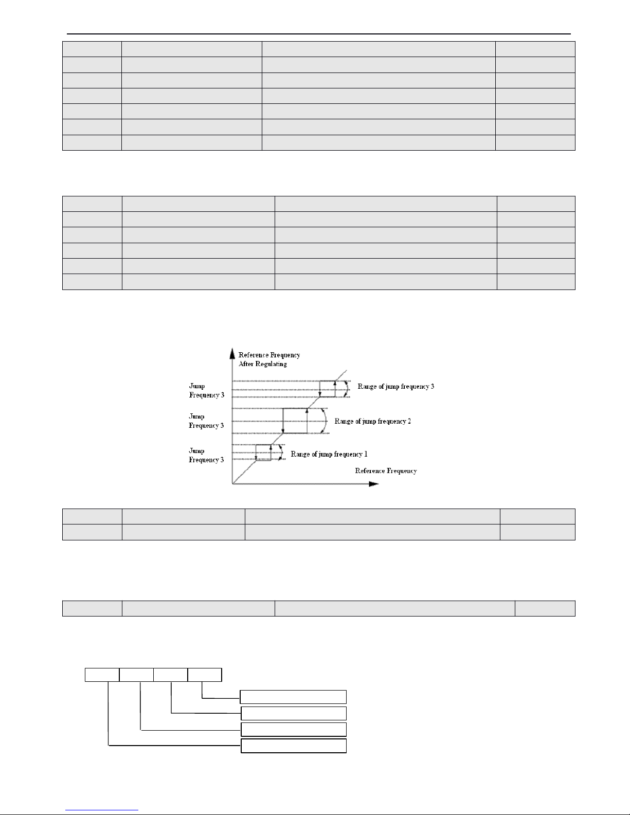
V5 series inverter
66
These frequencies will be used in multi-step speed operation and simple PLC operation, please refer to the instructions of
P4.00~P4.05 and
P8
.
P3.33~P3.38 define the functions that will let output frequency of the inverter avoid resonant point of mechnical load. The
reference frequency of the inverter can do jump operation in the certain range of some jump frequency point, as shown in
Fig.6-15
,
you can define three ranges of jump frequency at most.
Fig.
Fig.
Fig.
Fig. 4-15
4-15
4-15
4-15 Jump
Jump
Jump
Jump frequency
frequency
frequency
frequency and
and
and
and rang
rang
rang
rang e
e
e
e
Acculate run ning time to reach the reference time ( P3.39 ),the inverter will output signal, refer to function instruction of
P4.08~P4.09 .
P3.40 refers to the accu mu lating running time from factory till now .
P3.41 cont rols that if the monitor parameter s b-09 ~ b-24 can be displayed in parameter group
by
four figures.T he
parameter values are inhex which should be changed to binary ones according to the sequence of monitor parameters when
using. The relationship between four figures and parameters are shown in Fig.4-16.
Fig.
Fig.
Fig.
Fig. 4
4
4
4 - 16
16
16
16 Display
Display
Display
Display parameters
parameters
parameters
parameters selection
selection
selection
selection 1
1
1
1
Note:
Note:
Note:
Note: A:
A:
A:
A: Thousand
Thousand
Thousand
Thousand
’
’
’
’
s
s
s
s place,
place,
place,
place, B:
B:
B:
B: Hundred
Hundred
Hundred
Hundred
’
’
’
’
s
s
s
s place,
place,
place,
place,
P3.26
P3.26
P3.26
P3.26
Multi-frequency
Multi-frequency
Multi-frequency
Multi-frequency 1
1
1
1
Range
Range
Range
Range : lower
lower
lower
lower limit
limit
limit
limit of
of
of
of frequency
frequency
frequency
frequency ~ upper
upper
upper
upper limit
limit
limit
limit of
of
of
of frequency
frequency
frequency
frequency
5.00H
5.00H
5.00H
5.00H z
z
z
z
P3.27
P3.27
P3.27
P3.27
Multi-frequency
Multi-frequency
Multi-frequency
Multi-frequency 2
2
2
2
Range
Range
Range
Range : lower
lower
lower
lower limit
limit
limit
limit of
of
of
of frequency
frequency
frequency
frequency ~ upper
upper
upper
upper limit
limit
limit
limit of
of
of
of frequency
frequency
frequency
frequency
10.00H
10.00H
10.00H
10.00H z
z
z
z
P3.28
P3.28
P3.28
P3.28
Multi-frequency
Multi-frequency
Multi-frequency
Multi-frequency 3
3
3
3
Range
Range
Range
Range : lower
lower
lower
lower limit
limit
limit
limit of
of
of
of frequency
frequency
frequency
frequency ~ upper
upper
upper
upper limit
limit
limit
limit of
of
of
of frequency
frequency
frequency
frequency
20.00H
20.00H
20.00H
20.00H z
z
z
z
P3.29
P3.29
P3.29
P3.29
Multi-frequency
Multi-frequency
Multi-frequency
Multi-frequency 4
4
4
4
Range
Range
Range
Range : lower
lower
lower
lower limit
limit
limit
limit of
of
of
of frequency
frequency
frequency
frequency ~ upper
upper
upper
upper limit
limit
limit
limit of
of
of
of frequency
frequency
frequency
frequency
30.00H
30.00H
30.00H
30.00H z
z
z
z
P3.30
P3.30
P3.30
P3.30
Multi-frequency
Multi-frequency
Multi-frequency
Multi-frequency 5
5
5
5
Range
Range
Range
Range : lower
lower
lower
lower limit
limit
limit
limit of
of
of
of frequency
frequency
frequency
frequency ~ upper
upper
upper
upper limit
limit
limit
limit of
of
of
of frequency
frequency
frequency
frequency
40.00H
40.00H
40.00H
40.00H z
z
z
z
P3.31
P3.31
P3.31
P3.31
Multi-frequency
Multi-frequency
Multi-frequency
Multi-frequency 6
6
6
6
Range
Range
Range
Range : lower
lower
lower
lower limit
limit
limit
limit of
of
of
of frequency
frequency
frequency
frequency ~ upper
upper
upper
upper limit
limit
limit
limit of
of
of
of frequency
frequency
frequency
frequency
4
4
4
4 5
5
5
5 .00H
.00H
.00H
.00H z
z
z
z
P3.32
P3.32
P3.32
P3.32
Multi-frequency
Multi-frequency
Multi-frequency
Multi-frequency 7
7
7
7
Range
Range
Range
Range : lower
lower
lower
lower limit
limit
limit
limit of
of
of
of frequency
frequency
frequency
frequency ~ upper
upper
upper
upper limit
limit
limit
limit of
of
of
of frequency
frequency
frequency
frequency
5
5
5
5 0.00H
0.00H
0.00H
0.00H z
z
z
z
P3.33
P3.33
P3.33
P3.33
Jump
Jump
Jump
Jump frequency
frequency
frequency
frequency 1
1
1
1
Range
Range
Range
Range : 0.00
0.00
0.00
0.00 - 500.00Hz
500.00Hz
500.00Hz
500.00Hz
0.00Hz
0.00Hz
0.00Hz
0.00Hz
P3.34
P3.34
P3.34
P3.34
1
1
1
1 Range
Range
Range
Range of
of
of
of j
j
j
j ump
ump
ump
ump frequency
frequency
frequency
frequency 1
1
1
1
Range
Range
Range
Range : 0.00
0.00
0.00
0.00 - 30.00Hz
30.00Hz
30.00Hz
30.00Hz
0.00Hz
0.00Hz
0.00Hz
0.00Hz
P3.35
P3.35
P3.35
P3.35
Jump
Jump
Jump
Jump frequency
frequency
frequency
frequency 2
2
2
2
Range
Range
Range
Range : 0.00
0.00
0.00
0.00 - 500.00Hz
500.00Hz
500.00Hz
500.00Hz
0.00Hz
0.00Hz
0.00Hz
0.00Hz
P3.36
P3.36
P3.36
P3.36
Range
Range
Range
Range of
of
of
of jump
jump
jump
jump frequency
frequency
frequency
frequency 2
2
2
2
Range
Range
Range
Range : 0.00
0.00
0.00
0.00 - 30.00Hz
30.00Hz
30.00Hz
30.00Hz
0.00Hz
0.00Hz
0.00Hz
0.00Hz
P3.37
P3.37
P3.37
P3.37
Jump
Jump
Jump
Jump frequency
frequency
frequency
frequency 3
3
3
3
Range
Range
Range
Range : 0.00
0.00
0.00
0.00 - 500.00Hz
500.00Hz
500.00Hz
500.00Hz
0.00Hz
0.00Hz
0.00Hz
0.00Hz
P3.38
P3.38
P3.38
P3.38
Range
Range
Range
Range of
of
of
of jump
jump
jump
jump frequency
frequency
frequency
frequency 3
3
3
3
Range
Range
Range
Range : 0.00
0.00
0.00
0.00 - 30.00Hz
30.00Hz
30.00Hz
30.00Hz
0.00Hz
0.00Hz
0.00Hz
0.00Hz
P3.39
P3.39
P3.39
P3.39
Set
Set
Set
Set running
running
running
running time
time
time
time
Range
Range
Range
Range : 0
0
0
0 ~ 65.535K
65.535K
65.535K
65.535K hour
hour
hour
hour
0
0
0
0 .000K
.000K
.000K
.000K
P3.40
P3.40
P3.40
P3.40
Accu
Accu
Accu
Accu mu
mu
mu
mu late
late
late
late running
running
running
running time
time
time
time
Range
Range
Range
Range : 0
0
0
0 ~ 65.535K
65.535K
65.535K
65.535K hour
hour
hour
hour
*
*
*
*
P3.41
P3.41
P3.41
P3.41
Display
Display
Display
Display parameters
parameters
parameters
parameters selection
selection
selection
selection 1
1
1
1
Range
Range
Range
Range : 0000
0000
0000
0000 ~ FFFF
FFFF
FFFF
FFFF
0000
0000
0000
0000
b-09 ~ b-12
b-13 ~ b-16
b-17 ~ b-20
b-21 ~ b-24
ABC
D
Page 73
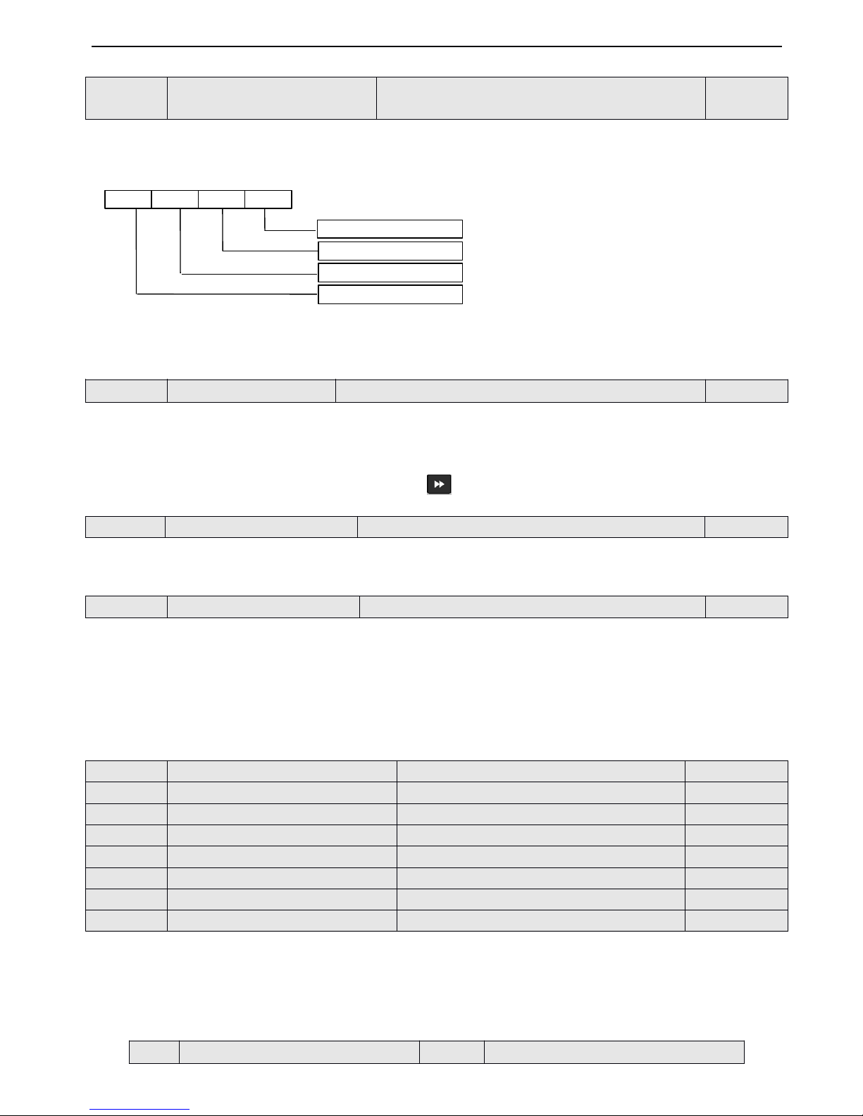
V5 series inverter
67
C:
C:
C:
C: Ten
Ten
Ten
Ten
’
’
’
’
s
s
s
s place,
place,
place,
place, D:
D:
D:
D: Unit
Unit
Unit
Unit
’
’
’
’
s
s
s
s place
place
place
place
P3.42 control s that if b-25 ~ b-40 can be displayed in parameter group
by
four figures. The parameter values are in hex
which should be changed to binary ones according to the sequency of monitor parameters when using.The relationship
between four figures and parameters are shown in Fig. 4-17.
Fig.
Fig.
Fig.
Fig. 4
4
4
4 - 17
17
17
17 Display
Display
Display
Display parameters
parameters
parameters
parameters selection
selection
selection
selection 2
2
2
2
(
(
(
( R
R
R
R efer
efer
efer
efer to
to
to
to P73
P73
P73
P73 for
for
for
for b-09
b-09
b-09
b-09 ~
~
~
~ b-40
b-40
b-40
b-40 )
)
)
)
Note:
Note:
Note:
Note: A:
A:
A:
A: Thousand
Thousand
Thousand
Thousand
’
’
’
’
s
s
s
s place,
place,
place,
place, B:
B:
B:
B: Hundred
Hundred
Hundred
Hundred
’
’
’
’
s
s
s
s place,
place,
place,
place,
C:
C:
C:
C: Ten
Ten
Ten
Ten
’
’
’
’
s
s
s
s place,
place,
place,
place, D:
D:
D:
D: Unit
Unit
Unit
Unit
’
’
’
’
s
s
s
s place
place
place
place
Ten’s place,unit’s place : used to set stop status
Thousand
’
s place, hundred’s place : used to set running status
Example: When you want to let the inverter display current value in running status and display DC injucetion bus voltage
value, you can se t P3.43=0304
.
You
can also press the key to view other monitor parameters .
P3.44 : It is used to set proportion value between display value and output frequency of monitor param eter b-14.
Display
Display
Display
Display value
value
value
value of
of
of
of b
b
b
b -
-
-
- 14
14
14
14 =
=
=
= Output
Output
Output
Output frequency
frequency
frequency
frequency of
of
of
of inverter
inverter
inverter
inverter × P3.44
P3.44
P3.44
P3.44
P3.45 is used to select the usage of JOG/REV key in the panel , the references are shown below:
0 : select to JOG
1 : select to REV
4-2-5
4-2-5
4-2-5
4-2-5
.
.
.
.
Function
Function
Function
Function parameters
parameters
parameters
parameters of
of
of
of terminal
terminal
terminal
terminal ( Group
Group
Group
Group P4
P4
P4
P4 )
Multi-function input terminals X1~X8 support various functions which you can select freely to satisfy your
requirement
.
You
can define the function of X1 ~ X8 by setting the value of P4.00 ~ P4.07
,
refer to Table 4 - 1 for
details, Among these terminals, X7 corresponds to FWD and X8 corresponds to REV .
Table
Table
Table
Table
4-1
4-1
4-1
4-1 Multi-function
Multi-function
Multi-function
Multi-function selection
selection
selection
selection
P3.42
P3.42
P3.42
P3.42
Display
Display
Display
Display parameters
parameters
parameters
parameters
selection
selection
selection
selection 2
2
2
2
Range
Range
Range
Range : 00
00
00
00 00
00
00
00 ~ FFFF
FFFF
FFFF
FFFF
0000
0000
0000
0000
P3.43
P3.43
P3.43
P3.43
Display
Display
Display
Display parameters
parameters
parameters
parameters 3
3
3
3
Range
Range
Range
Range : 0000
0000
0000
0000 ~ 4040
4040
4040
4040
0001
0001
0001
0001
P3.44
P3.44
P3.44
P3.44
Display
Display
Display
Display coefficient
coefficient
coefficient
coefficient without
without
without
without unit
unit
unit
unit
Range
Range
Range
Range : 0.1
0.1
0.1
0.1 ~ 60.0
60.0
60.0
60.0
1.0
1.0
1.0
1.0
P3.45
P3.45
P3.45
P3.45
JOG/REV
JOG/REV
JOG/REV
JOG/REV shift
shift
shift
shift control
control
control
control mode
mode
mode
mode
Range
Range
Range
Range : 0
0
0
0 ,
,
,
, 1
1
1
1
0
0
0
0
P4.00
P4.00
P4.00
P4.00
Function
Function
Function
Function selection
selection
selection
selection of
of
of
of input
input
input
input terminal
terminal
terminal
terminal X1
X1
X1
X1
Range
Range
Range
Range : 0
0
0
0 ~ 37
37
37
37
1
1
1
1
P4.01
P4.01
P4.01
P4.01
Function
Function
Function
Function selection
selection
selection
selection of
of
of
of input
input
input
input terminal
terminal
terminal
terminal X
X
X
X 2
2
2
2
Range
Range
Range
Range : 0
0
0
0 ~ 37
37
37
37
2
2
2
2
P4.02
P4.02
P4.02
P4.02
Function
Function
Function
Function selection
selection
selection
selection of
of
of
of input
input
input
input terminal
terminal
terminal
terminal X
X
X
X 3
3
3
3
Range
Range
Range
Range : 0
0
0
0 ~ 37
37
37
37
3
3
3
3
P4.03
P4.03
P4.03
P4.03
Function
Function
Function
Function selection
selection
selection
selection of
of
of
of input
input
input
input terminal
terminal
terminal
terminal X
X
X
X 4
4
4
4
Range
Range
Range
Range : 0
0
0
0 ~ 37
37
37
37
10
10
10
10
P4.04
P4.04
P4.04
P4.04
Function
Function
Function
Function selection
selection
selection
selection of
of
of
of input
input
input
input terminal
terminal
terminal
terminal X
X
X
X 5
5
5
5
Range
Range
Range
Range : 0
0
0
0 ~ 37
37
37
37
17
17
17
17
P4.05
P4.05
P4.05
P4.05
Function
Function
Function
Function selection
selection
selection
selection of
of
of
of input
input
input
input terminal
terminal
terminal
terminal X
X
X
X 6
6
6
6
Range
Range
Range
Range : 0
0
0
0 ~ 37
37
37
37
18
18
18
18
P4.06
P4.06
P4.06
P4.06
Function
Function
Function
Function selection
selection
selection
selection of
of
of
of input
input
input
input terminal
terminal
terminal
terminal X
X
X
X 7
7
7
7
Range
Range
Range
Range : 0
0
0
0 ~ 37
37
37
37
0
0
0
0
P4.07
P4.07
P4.07
P4.07
Function
Function
Function
Function selection
selection
selection
selection of
of
of
of input
input
input
input terminal
terminal
terminal
terminal X
X
X
X 8
8
8
8
Range
Range
Range
Range : 0
0
0
0 ~ 37
37
37
37
0
0
0
0
Setting
Setting
Setting
Setting
Functions
Functions
Functions
Functions
Setting
Setting
Setting
Setting
Functions
Functions
Functions
Functions
b- 25 ~ b-28
b- 29 ~ b- 32
b- 33 ~ b- 36
b- 37 ~ b- 40
ABC
D
Page 74
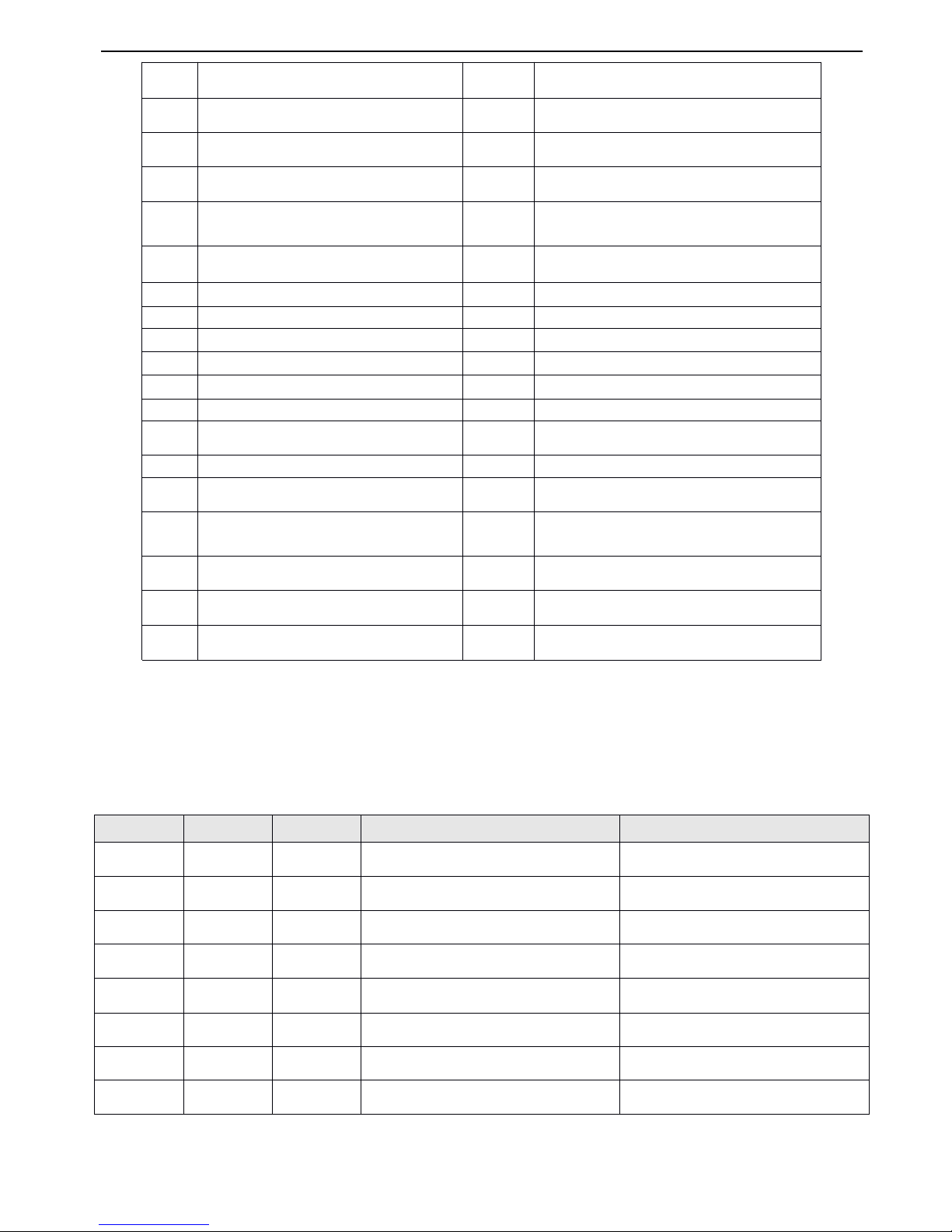
V5 series inverter
68
I ntroduction s of the functions shown in Table4-1:
1
1
1
1 ~ 3
3
3
3 : Multi-step
Multi-step
Multi-step
Multi-step speed
speed
speed
speed control
control
control
control terminals
terminals
terminals
terminals
.
.
.
.
Up to
7
speed reference can be set
by
different ON/OFF (open/close)
combination of the function terminals,at the same time,you can select corresponding Acc/Dec time
.
Table
Table
Table
Table
4-2
4-2
4-2
4-2 On/
On/
On/
On/ O
O
O
O ff
ff
ff
ff combination
combination
combination
combination of
of
of
of function
function
function
function terminals
terminals
terminals
terminals
The above frequenc ies can be used in multi-step speed running and simple PLC running, this manual take multi-step speed
running as an example.
0
Control terminal l eave unused
19
F requency selector 1
1
Multi-step speed control terminal 1
20
F requency selector 2
2
Multi-step speed control terminal 2
21
F requency selector 3
3
Multi-step speed control terminal 3
22
Terminal control mode is forcibly enabled
4
Exteral terminal for forward jog operation
23
Control mode selector 1
5
Exteral terminal for reverse jog operation
24
Control mode selector 2
6
Acc/Dec time terminal 1
25
Start traverse operation
7
Acc/Dec time terminal 2
26
Res e t traverse operatio n
8
Acc/Dec time terminal 3
27
Close-loop disabled
9
3-wire operation control
28
Pause the PLC operation
10
Coast-to-stop ( FRS )
29
PLC d isabled
11
External stop command
30
Reset PLC stopping status
12
DC injection braking command DB
31
Frequency reference is input via CI
13
Inverter running prohibit
32
Counter’s trig signal input
14
Frequency ramp up ( UP )
33
Counter’s zero-cleaning signal input
15
Frequency ramp down ( DOWN )
34
External interrupt input
16
Acc/Dec prohibit
35
P ulse frequency input ( only valid for X6 )
17
Reset signal ( clear fault )
36
Autual length clearing input
18
External fault signal normally open input
37
K
K
K
K
3
3
3
3
K
K
K
K
2
2
2
2
K
K
K
K
1
1
1
1
Frequency
Frequency
Frequency
Frequency setting
setting
setting
setting
Acc/Dec
Acc/Dec
Acc/Dec
Acc/Dec time
time
time
time
OFF
OFF
OFF
Common running frequency
Acc/Dec
Acc/Dec
Acc/Dec
Acc/Dec time
time
time
time 1
OFF
OFF
ON
Multi-step frequency 1
Acc/Dec
Acc/Dec
Acc/Dec
Acc/Dec time
time
time
time 1
OFFONOFF
Multi-step frequency 2
Acc/Dec
Acc/Dec
Acc/Dec
Acc/Dec time
time
time
time 2
OFFONON
Multi-step frequency 3
Acc/Dec
Acc/Dec
Acc/Dec
Acc/Dec time
time
time
time 3
ON
OFF
OFF
Multi-step frequency 4
Acc/Dec
Acc/Dec
Acc/Dec
Acc/Dec time
time
time
time 4
ON
OFFONMulti-step frequency 5
Acc/Dec
Acc/Dec
Acc/Dec
Acc/Dec time
time
time
time 5
ONONOFF
Multi-step frequency 6
Acc/Dec
Acc/Dec
Acc/Dec
Acc/Dec time
time
time
time 6
6
6
6
ONONON
Multi-step frequency 7
Acc/Dec
Acc/Dec
Acc/Dec
Acc/Dec time
time
time
time 7
Page 75
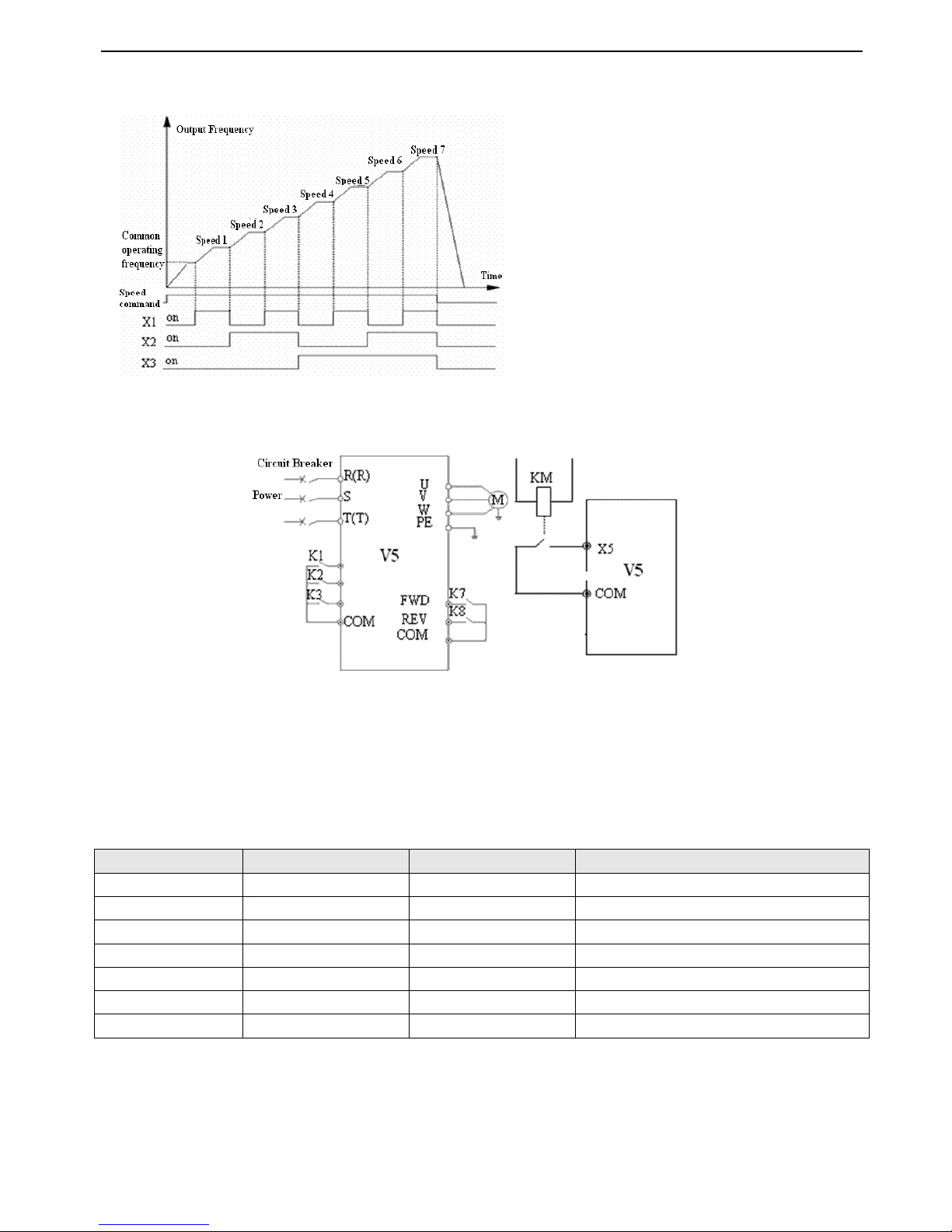
V5 series inverter
69
The definition of X1, X2 and X3 are shown below:
P4.00=1,P4.01=2,P4.03=3 , X1,X2 and X3 can be used to achieve multi-step speed operation
,
as shown in Fig.4-18.
Fig.
Fig.
Fig.
Fig. 4-18
4-18
4-18
4-18 Multi-step
Multi-step
Multi-step
Multi-step speed
speed
speed
speed operation
operation
operation
operation
In Fig.4-19 terminal control is selected, the operating direction is controlled
by
K7、 K
8
.
In Fig.4-18, Common operating
frequency or 1 ~
7
multi-step frequency can be controlled
by
different combination of K1,
K2,
K3.
Fig.
Fig.
Fig.
Fig. 4
4
4
4 - 19
19
19
19 Wire
Wire
Wire
Wire of
of
of
of multi-step
multi-step
multi-step
multi-step Fig.
Fig.
Fig.
Fig. 4-20
4-20
4-20
4-20 External
External
External
External device
device
device
device fault
fault
fault
fault input
input
input
input
4
4
4
4 ~ 5
5
5
5:External
External
External
External terminals
terminals
terminals
terminals control
control
control
control jog
jog
jog
jog operation
operation
operation
operation JOGP/JOGR.
JOGP/JOGR.
JOGP/JOGR.
JOGP/JOGR. When choose terminal control ( P0.03=1 ),JOGP is used a s
forward jog operation , JOGR is used as reverse jog operatio n. Jog operating frequency and jog Acc/Dec time are defined in
P3.06 ~P3.08 .
6
6
6
6 ~ 8
8
8
8 : Acc/Dec
Acc/Dec
Acc/Dec
Acc/Dec time
time
time
time selection
selection
selection
selection
Table
Table
Table
Table
4-3
4-3
4-3
4-3 Acc/Dec
Acc/Dec
Acc/Dec
Acc/Dec time
time
time
time selection
selection
selection
selection
Through
the
ON/OFF combination of
Dec
time
terminal,
you
can select
dec
time 1~7 .
9
9
9
9
:
:
:
:
3-wire
3-wire
3-wire
3-wire operation
operation
operation
operation control
control
control
control ,
,
,
, r
efertofunction
al instruction
of P4.08.
10
10
10
10 :
:
:
: Coast-to-stop
Coast-to-stop
Coast-to-stop
Coast-to-stop ( FRS
FRS
FRS
FRS ) ,
,
,
, this function has the same meaning as the description in P2.05, while here it is a c hieved
by
terminal controlling which is conve ni ent for remote control .
1
1
1
1
1
1
1
1 :
:
:
: External
External
External
External stop
stop
stop
stop command
command
command
command ,
,
,
, this command is valid for all the running channels and it can stop the inverter according to the
setting mode in P2.05.
Terminal
Terminal
Terminal
Terminal 3
3
3
3
Terminal
Terminal
Terminal
Terminal 2
2
2
2
Terminal
Terminal
Terminal
Terminal 1
1
1
1
Acc/Dec
Acc/Dec
Acc/Dec
Acc/Dec time
time
time
time selection
selection
selection
selection
OFF
OFF
OFF
Acc time 1/ Dec time 1
OFF
OFFONAcc time 2/ Dec time 2
OFFONOFF
Acc time 3/ Dec time 3
OFFONON
Acc time 4/ Dec time 4
ON
OFF
OFF
Acc time 5/ Dec time 5
ON
OFFONAcc time 6/ Dec time 6
ONONOFF
Acc time 7/ Dec time 7
Page 76
V5 series inverter
70
12
12
12
12
:
:
:
:
DC
DC
DC
DC injection
injection
injection
injection braking
braking
braking
braking command
command
command
command DB
DB
DB
DB ,
,
,
, t he terminal
can
be
used
to
perform
DC injection
braking
to
the
motor
thatisrunning
so as
to
realize the emergent
stop
and
accurate
location of
the
motor.
Initial
braking
frequency,
braking time
and
braking current
are
defined
by
P 2.0 6 ~ P 2.08.
Braking time
is
the greater value
between
P2.07
and
the effective
continuous time
defined
by
this
control terminal.
1
1
1
1 3
3
3
3 : Inverter
Inverter
Inverter
Inverter running
running
running
running prohibit
prohibit
prohibit
prohibit
.
.
.
.
When
the
terminalisenabled, the
inverter
thatisoperating
will
coasttostop
anditis
prohibite
d
to restart.
This functionismainly used
in
application
with requirements of
safety
protection.
14
14
14
14 ~
~
~
~ 15
15
15
15
:
:
:
:
Frequency
Frequency
Frequency
Frequency ramp
ramp
ramp
ramp up
up
up
up (
(
(
( UP
UP
UP
UP )/Frequency
)/Frequency
)/Frequency
)/Frequency ramp
ramp
ramp
ramp down(DOW
down(DOW
down(DOW
down(DOW N
N
N
N
)
)
)
)
The terminal can be used to increase or decrease the
frequency.Its function is the same with operating keys on the panel, which enables remote control. This terminal is enabled
when P 0.0 1 = 3.Increase or decrease rate is determined
by
P4
.09.
16
16
16
16
:
:
:
:
Acc/Dec
Acc/Dec
Acc/Dec
Acc/Dec prohibit
prohibit
prohibit
prohibit
.
.
.
.
T he terminal can make the motor operate at present speed without being influenced
by
external
signal (except stopping command).
Note
Note
Note
Note
:
:
:
:
Disabled in normal dec -to-stop.
17
17
17
17
:
:
:
:
Reset
Reset
Reset
Reset signal
signal
signal
signal
.
.
.
.
T he
inverter can
be
reset
via
this
terminal when
the
inverter
hasafault.
The function of
this
terminalisthe
same
with
that
of on
the
panel.
18
18
18
18
:
:
:
:
External
External
External
External fault
fault
fault
fault signal
signal
signal
signal normally
normally
normally
normally open
open
open
open input
input
input
input
.
.
.
.
T he fault signal of external equipment can be input via the terminal, which
is convenient for the inverter to monitor the external equipment. Once the inverter receives the fault signal, it will display
“ E -13 ”.Refer to Fig.4-20 .
19
19
19
19 ~
~
~
~ 21
21
21
21
:
:
:
:
Frequency
Frequency
Frequency
Frequency selector
selector
selector
selector 1
1
1
1
.
.
.
.
Different ON/OFF combination of terminals 19, 20 and 21 can sel ect reference frequency as
shown in Table
4-4.The inverter will be active this function and P0.01 later.
Table
Table
Table
Table
4-4
4-4
4-4
4-4 Frequency
Frequency
Frequency
Frequency selector
selector
selector
selector
22
22
22
22 : T erminal
Terminal
Terminal
Terminal control
control
control
control mode
mode
mode
mode is
is
is
is forcibly
forcibly
forcibly
forcibly enabled
enabled
enabled
enabled .
.
.
. When this terminal is enabled, the running mode will be turn to terminal
control
.
23
23
23
23 ~ 24
24
24
24
:
:
:
:
Control
Control
Control
Control mode
mode
mode
mode selection.
selection.
selection.
selection. Control mode can be selected via ON/OFF combination of terminals. The inverter will be
active this function and P0.03 later .
Table
Table
Table
Table
4-5
4-5
4-5
4-5 Control
Control
Control
Control mode
mode
mode
mode
25
25
25
25 : Start
Start
Start
Start traverse
traverse
traverse
traverse operation.
operation.
operation.
operation. When the traverse operation is as “ manual ”,the traverse function will be enabled if this
terminal is enabled, see Group P9 for details.
26
26
26
26 : Res
Res
Res
Res e
e
e
e
t
t
t
t
traverse
traverse
traverse
traverse operation
operation
operation
operation
.
.
.
.
No matter the travers e operation is “ Manual ” or “ Auto ”,close-loop this terminal will clear
all the memor ized information of traverse operation
.
Disconncet this terminal can restart traverse operation. Refer to P9 for
parameters instruction.
27
27
27
27 : Close-loop
Close-loop
Close-loop
Close-loop disabled
disabled
disabled
disabled
.
.
.
.
The terminal can be used to flexib le switching the close-loop operation and low level operation
,
Frequency
Frequency
Frequency
Frequency selector
selector
selector
selector 3
3
3
3
Frequency
Frequency
Frequency
Frequency selector
selector
selector
selector 2
2
2
2
Frequency
Frequency
Frequency
Frequency selector
selector
selector
selector 1
1
1
1
Frequency
Frequency
Frequency
Frequency selector
selector
selector
selector
OFF
OFF
OFF
Hold the setting
OFF
OFF
ON
Digital setting
OFFONOFF
Terminal UP/DOWN setting
OFFONON
Serial port setting
ON
OFF
OFF
VI
ON
OFF
ON
CI
ONONOFF
PULSE
ONONON
Combination setting
( refer to P3.01 )
Terminal
Terminal
Terminal
Terminal 2
2
2
2
Terminal
Terminal
Terminal
Terminal 1
1
1
1
Control
Control
Control
Control mode
mode
mode
mode
OFF
OFF
Hold the control mode
OFF
ON
Panel control mode
ON
OFF
Terminal control mode
ON
ON
Serial port control mode
Page 77
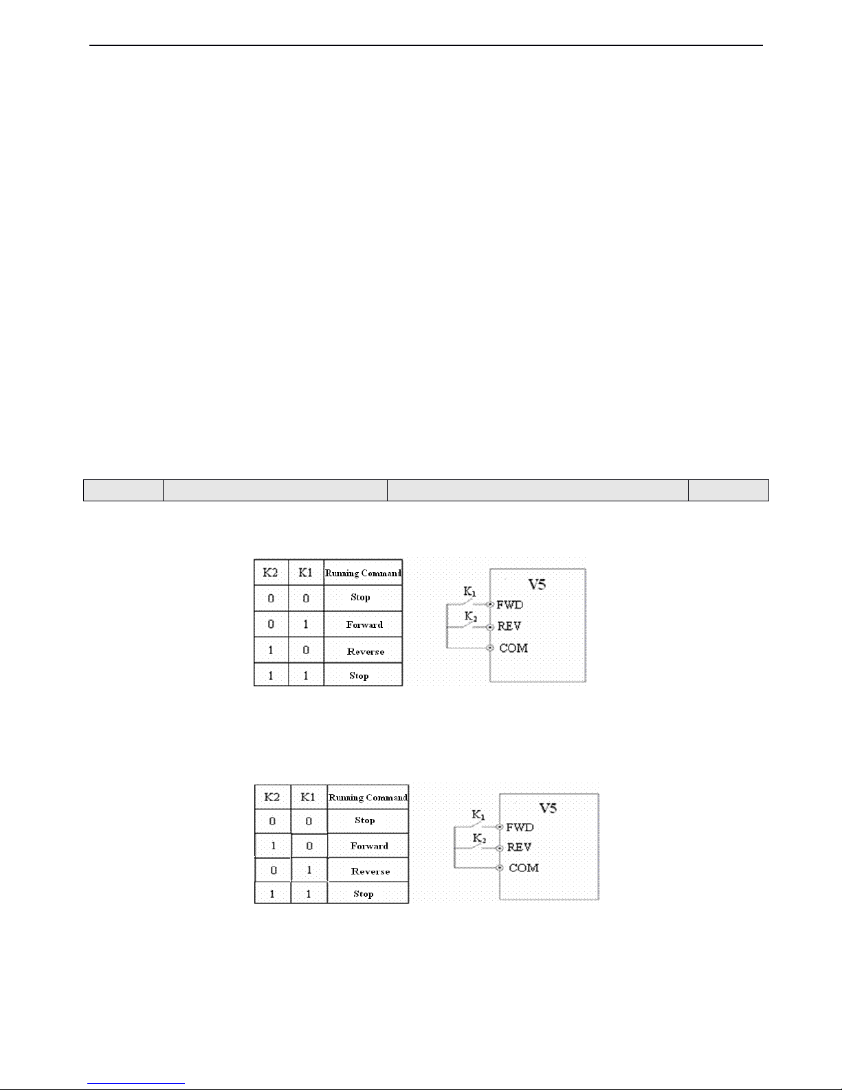
V5 series inverter
71
and the setting of start/stop control, direction, Acc/Dec time mode in low level operation.
Note
Note
Note
Note : Switching between close-loop operation and low level operation can be realized only when close-loop is enabled
( P7.00 =1 ).
28
28
28
28 : Pause
Pause
Pause
Pause the
the
the
the PLC
PLC
PLC
PLC operation
operation
operation
operation
.
.
.
.
The terminal is used to realize pause control, when this terminal is enabled, the inverter wil l
run in
0
Hz and PLC will not accumulate time; when this terminal is disabled, inverter will start with auto speed and PLC
continue to run. Refer to group P8 for instructions.
29
29
29
29 : PLC
PLC
PLC
PLC disabled
disabled
disabled
disabled.This terminal can be used to flexible switching the PLC operation and low level operation.
Note
Note
Note
Note:The switching between PLC operation and low level operation only when PLC is running ( the unit’s place of P8.00 i s
not to0)
30
30
30
30 : Reset PLC stopping status. When PLC is in stopping status, the enabled terminal can clear PLC running stage
,
running
time, running frequency and other informations of PLC stopping memory. Refer to P8 for instructions.
31
31
31
31 : Frequency
Frequency
Frequency
Frequency reference
reference
reference
reference is
is
is
is input
input
input
input via
via
via
via CI
CI
CI
CI.Frequency reference is input via CI forcibly when the terminal is enabled, and it
will involute when the terminal is disabled.
32
32
32
32 : Counter
Counter
Counter
Counter
’
’
’
’
s
s
s
s trig
trig
trig
trig signal
signal
signal
signal input
input
input
input
.
.
.
.
T his terminal is used to input pulse signal to the internal counter of the inverter.The
highest pulse frequency is 200Hz. The present counting value can be saved at power off. See P4.2 2 and P4.2 3 for details.
33
33
33
33 : Counter
Counter
Counter
Counter
’
’
’
’
s
s
s
s zero-cleaning
zero-cleaning
zero-cleaning
zero-cleaning signal
signal
signal
signal input
input
input
input .
.
.
. I t is used to clear the counter to zero in conjunction with terminal 43.
34
34
34
34 : External
External
External
External interrupt
interrupt
interrupt
interrupt input
input
input
input .
.
.
. After receiving external interrupt input signal, inverter will lock output and running in0Hz
,
once the interrupt input signal release,the inverter will start on the fly and continue the PLC operation.
35
35
35
35
:
Pulse
Pulse
Pulse
Pulse frequency
frequency
frequency
frequency input
input
input
input ( only
only
only
only valid
valid
valid
valid for
for
for
for X6
X6
X6
X6).
.
.
. This terminal can receive pulse signal as reference frequency , please re fer
to P1.11~P1.15 for the relationship between pulse frequency of input signal and reference frequency.
36:
36:
36:
36: Autual
Autual
Autual
Autual length
length
length
length clearing
clearing
clearing
clearing input
input
input
input
.
.
.
.
If this terminal is enabled, the autual length parameter P9.09 will be cleared to zero.
This parameter defineds four operaion modes via which external terminals can control inverter.
0
0
0
0 : 2-wire
2-wire
2-wire
2-wire control
control
control
control mode
mode
mode
mode 1
1
1
1
Fig.
Fig.
Fig.
Fig. 4-21
4-21
4-21
4-21 2-wire
2-wire
2-wire
2-wire operation
operation
operation
operation mode
mode
mode
mode 1
1
1
1
1
1
1
1 : 2-wire
2-wire
2-wire
2-wire control
control
control
control mode
mode
mode
mode 2
2
2
2
Fig.
Fig.
Fig.
Fig. 4-22
4-22
4-22
4-22 2-wire
2-wire
2-wire
2-wire operation
operation
operation
operation mode
mode
mode
mode 2
2
2
2
2
2
2
2 : 3-wire
3-wire
3-wire
3-wire control
control
control
control mode
mode
mode
mode 1
1
1
1
SB1 : Stop button
SB2 : Forward button
SB3 : Reverse button
P4.08
P4.08
P4.08
P4.08
FWD/REV
FWD/REV
FWD/REV
FWD/REV operation
operation
operation
operation mode
mode
mode
mode selection
selection
selection
selection
Range
Range
Range
Range : 0
0
0
0 ~ 3
3
3
3
0
0
0
0
Page 78
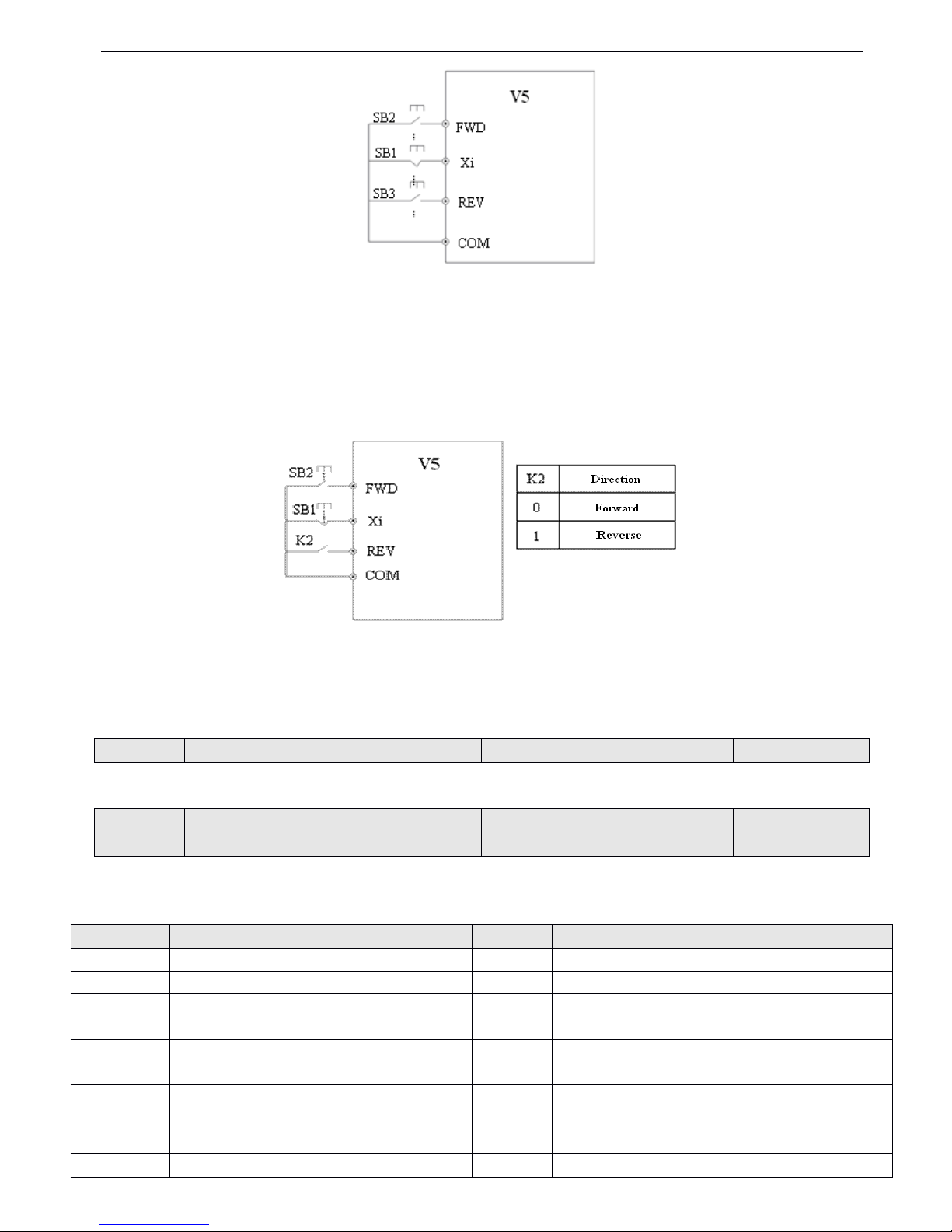
V5 series inverter
72
Fig.
Fig.
Fig.
Fig. 4-23
4-23
4-23
4-23 3-wire
3-wire
3-wire
3-wire operation
operation
operation
operation mode
mode
mode
mode 1
1
1
1
Xi is the multi-function input terminal of X1~X6,here you should define its function as N o.9 “ 3-wire control mode ” .
3
3
3
3 : 3-wire
3-wire
3-wire
3-wire control
control
control
control mode
mode
mode
mode 2
2
2
2
SB1 : Stop button
SB2 : Running button
Fig.
Fig.
Fig.
Fig. 4
4
4
4 -24
-24
-24
-24 3-wire
3-wire
3-wire
3-wire control
control
control
control mode
mode
mode
mode 2
2
2
2
Xi is the multi-function input terminal of X1~X6 , here you should define its function as No.9 “ 3-wire control mode ” .
Note
Note
Note
Note : When the inverter stops due to fault, it will start immediately if the terminal control mode and terminal FWD/REV
are enabled and the fault is cleared.
This parameter defines the change rate of reference frequency that is changed
by
UP/DOWN.
Bi-direction oper-collector output termin al OC , the options of this parameter are shown in T able 4-6 .
Table
Table
Table
Table
4-6
4-6
4-6
4-6 Functions
Functions
Functions
Functions of
of
of
of output
output
output
output terminals
terminals
terminals
terminals
P4.09
P4.09
P4.09
P4.09
UP/D
UP/D
UP/D
UP/D OW
OW
OW
OW N
N
N
N speed
speed
speed
speed rate
rate
rate
rate
Range
Range
Range
Range : 0.01
0.01
0.01
0.01 ~ 99.99H
99.99H
99.99H
99.99H z/s
z/s
z/s
z/s
1.00
1.00
1.00
1.00 H
H
H
H z/
z/
z/
z/ s
s
s
s
P4.10
P4.10
P4.10
P4.10
Bi-direction
Bi-direction
Bi-direction
Bi-direction open-collector
open-collector
open-collector
open-collector output
output
output
output terminal
terminal
terminal
terminal OC
OC
OC
OC
Range
Range
Range
Range : 0
0
0
0 ~ 20
20
20
20
0
0
0
0
P4.11
P4.11
P4.11
P4.11
Relay
Relay
Relay
Relay output
output
output
output selector
selector
selector
selector
Range
Range
Range
Range : 0
0
0
0 ~ 20
20
20
20
15
15
15
15
Setting
Setting
Setting
Setting
Functions
Functions
Functions
Functions
Setting
Setting
Setting
Setting
Functions
Functions
Functions
Functions
0
Inverter running (RUN)
11
PLC is finished after one cycle running
1
Frequency arriving signal (FAR)
12
Specified counting value arriving
2
Frequency detection threshold (FDT1)
13
Mid counting value arriving
3
Frequency detection threshold (FDT2)
14
Inverter Ready running finished ( RDY )
4
Overload pre-alarm ( OL )
15
Inverter fault
5
Inverter under voltage locking ( LU )
16
Start frenquence running time
6
External fault stop ( EXT )
17
Start DC injection braking time
Page 79
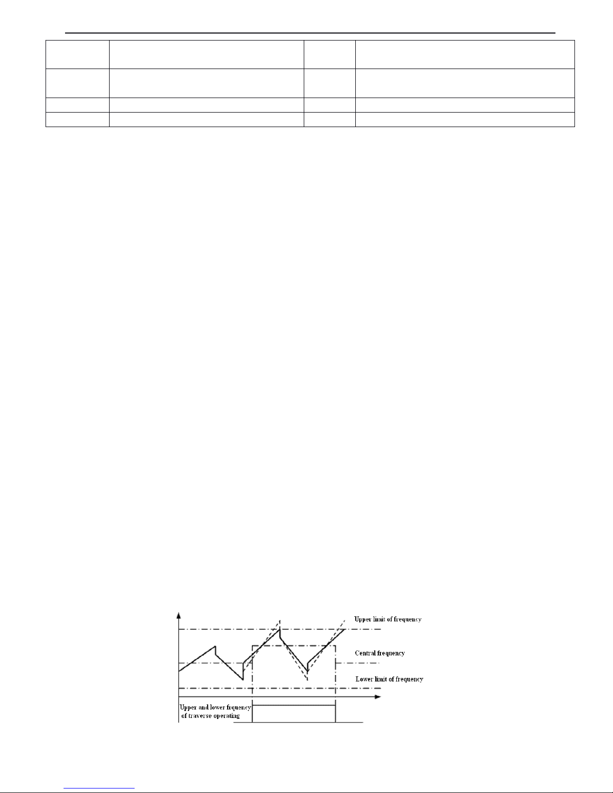
V5 series inverter
73
Instruction
Instruction
Instruction
Instruction s
s
s
s of
of
of
of the
the
the
the functions
functions
functions
functions shown
shown
shown
shown in
in
in
in
Tabel
Tabel
Tabel
Tabel
4-6
4-6
4-6
4-6 :
:
:
:
0
0
0
0 : Inverter
Inverter
Inverter
Inverter running
running
running
running ( RUN
RUN
RUN
RUN )
.
.
.
.
Inverter is in the running status and the terminal output s indication signal.
1
1
1
1 : Frequency
Frequency
Frequency
Frequency arriving
arriving
arriving
arriving signal
signal
signal
signal ( FAR
FAR
FAR
FAR )
.
.
.
.
Refer to P4.1 2 for function instruction .
2
2
2
2 : Frequency
Frequency
Frequency
Frequency detection
detection
detection
detection threshold
threshold
threshold
threshold ( FDT1
FDT1
FDT1
FDT1 )
.
.
.
.
Refer to P4.11~ P4.12 for function instruction.
3
3
3
3 : Frequency
Frequency
Frequency
Frequency detection
detection
detection
detection threshold
threshold
threshold
threshold ( FDT2
FDT2
FDT2
FDT2 )
.
Refer to P4.13 ~ P4.14 for function instruction.
4
4
4
4:Overload
Overload
Overload
Overload pre-alarm
pre-alarm
pre-alarm
pre-alarm ( OL
OL
OL
OL
)
.
.
.
.
If the output current is higher than the value defined
by
P4.24 and the time is longer than t he
value defined
by
P4.25, the inverter will output indicate signal s.This function is mainly used in pre-alarm.
5
5
5
5:Inverter
Inverter
Inverter
Inverter under
under
under
under voltage
voltage
voltage
voltage
locking
locking
locking
locking
( LU
LU
LU
LU
)
.
.
.
.
While inverter is in running process,if the DC injection bus voltage is lower t han
the limit value, “ E-11 ” will be displayed in LED and indicate signal will be output.
6
6
6
6:External
External
External
External fault
fault
fault
fault
stop
stop
stop
stop
( EXT
EXT
EXT
EXT
)
.
.
.
.
An i ndicate signal will be output if inverter outputs trigging signal caused
by
external fau lt.
7
7
7
7 : Output
Output
Output
Output frequency
frequency
frequency
frequency arrive
arrive
arrive
arrive upper
upper
upper
upper limit
limit
limit
limit ( FH
FH
FH
FH )
.
.
.
.
An i ndicate signal will be output if reference frequency ≥ upper limit of
frequency and the running frequency arrives the upper limit of frequency.
8
8
8
8 : Output
Output
Output
Output frequency
frequency
frequency
frequency arrive
arrive
arrive
arrive lower
lower
lower
lower limit
limit
limit
limit ( F
F
F
F L
L
L
L )
.
.
.
.
An i ndicate signal will be output if reference frequency ≤ lower limit of
frequency and the running frequency is lower than low limit of frequency.
9
9
9
9 : Inverter
Inverter
Inverter
Inverter zero
zero
zero
zero speed
speed
speed
speed running
running
running
running.The output frequency of inverter is0,
while the terminal will output indicate signal when
inverter is in running status.
10
10
10
10
:
Simple
Simple
Simple
Simple PLC
PLC
PLC
PLC Pause
Pause
Pause
Pause running
running
running
running finished
finished
finished
finished
.
.
.
.
An i ndicate signal ( single pulse signal, 500ms width ) will be output if the prese nt
stage of PLC operation is finised.
11:
11:
11:
11:
PLC
PLC
PLC
PLC is
is
is
is finished
finished
finished
finished after
after
after
after one
one
one
one cycle
cycle
cycle
cycle running.
running.
running.
running. An i ndicate signal ( single pulse signal, 500ms width ) will be output if one
cycle running of simple PLC is finished.
12
12
12
12 : Specified
Specified
Specified
Specified counting
counting
counting
counting value
value
value
value arriving
arriving
arriving
arriving
13
13
13
13 : Mid
Mid
Mid
Mid counting
counting
counting
counting value
value
value
value arriving
arriving
arriving
arriving
12
, 13 refer to P4.22~P4.23 for function instruction.
1
1
1
1 4
4
4
4:Inverter
Inverter
Inverter
Inverter Ready
Ready
Ready
Ready running
running
running
running
finished
finished
finished
finished
( RDY
RDY
RDY
RDY). If RDY signal is output, it means the drive has no fault, its DC bus voltag e is
normal and it can receive starting command.
1
1
1
1 5
5
5
5 : Inverter
Inverter
Inverter
Inverter fault.
fault.
fault.
fault. If there is fault with inverter, indicate signal will be output.
16
16
16
16 : Start
Start
Start
Start frenquence
frenquence
frenquence
frenquence running
running
running
running time
time
time
time
17
17
17
17 : Start
Start
Start
Start DC
DC
DC
DC injection
injection
injection
injection braking
braking
braking
braking time
time
time
time
18
18
18
18 : Stop
Stop
Stop
Stop braking
braking
braking
braking time
time
time
time
19
19
19
19 : Upper
Upper
Upper
Upper and
and
and
and lower
lower
lower
lower limits
limits
limits
limits of
of
of
of traverse
traverse
traverse
traverse operating
operating
operating
operating frequency
frequency
frequency
frequency .
.
.
. A n indicat e signal will be output if the traverse operating
frequency calculated
by
central frequency is higher than upper limit of frequency ( P0.19 ) or lower than the lower limit of
frequency (F0. 20 ), as shown in Fig. 4-25.
Fig.
Fig.
Fig.
Fig. 4-25
4-25
4-25
4-25 Upper
Upper
Upper
Upper and
and
and
and lower
lower
lower
lower limits
limits
limits
limits of
of
of
of traverse
traverse
traverse
traverse operating
operating
operating
operating frequency
frequency
frequency
frequency
7
Output frequency arrive upper limit ( FH )
18
Stop braking time
8
Output frequency arrive lower limit ( FL )
19
High and lower limits of traverse operating frequency
9
Inverter zero speed running
20
set running time arriving
10
Simple PLC Pause running finished
21
Page 80
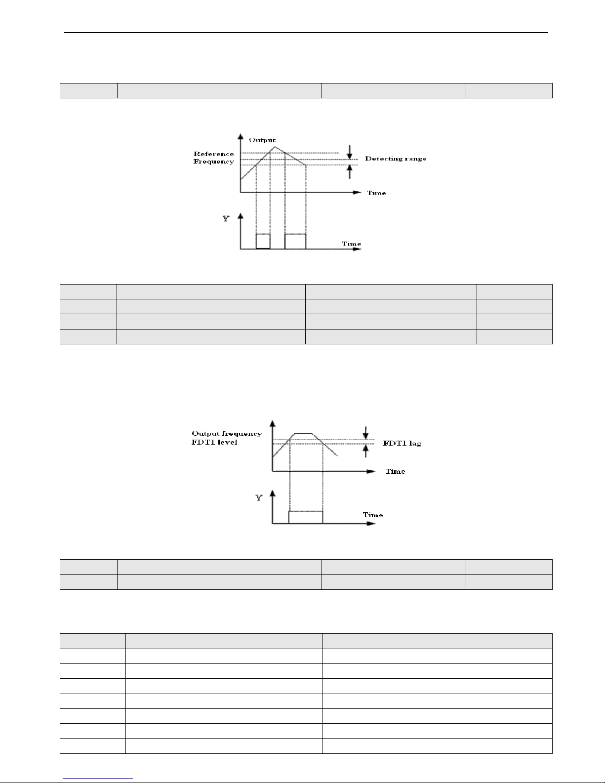
V5 series inverter
74
20
20
20
20 : Set running time arriving .
.
.
. When the accumulat ing time ( P3.40 ) arrive the reference time (P3.39), an indication signal
will be output.
This parameter is the additional definition of No.
1
function in Table4-6. As shown in Fig.4-26, when the output frequency
of inverter is within the detecting range of reference frequency, pulse signal will be output.
Fig
Fig
Fig
Fig 4-26
4-26
4-26
4-26 Frequency
Frequency
Frequency
Frequency arriving
arriving
arriving
arriving signal
signal
signal
signal
P4.13 ~ P4.14 is the additional definition of No.2 function in Fig.4-6, P 4.15 ~ P4.16 is the additional definition of No.3
function in Fig.4-6,The both have the same usage and the following take P4.13 ~ P4.14 as an example to introduce.When
the output frequency over a certain frequency( FDT1 level ),indication signal will be output until the output frequency fall to
the value which is lower than the certain frequency (FDT1 level - FDT1 lag ) , as shown in Fig. 4-27 .
Fig.
Fig.
Fig.
Fig. 4-27
4-27
4-27
4-27 FDT
FDT
FDT
FDT level
level
level
level
Table
Table
Table
Table
4-7
4-7
4-7
4-7 Output
Output
Output
Output terminals
terminals
terminals
terminals
P4.12
P4.12
P4.12
P4.12
Detecting
Detecting
Detecting
Detecting range
range
range
range of
of
of
of frequency
frequency
frequency
frequency arrive
arrive
arrive
arrive ( F AR
FAR
FAR
FAR )
Range
Range
Range
Range : 0.00
0.00
0.00
0.00 ~ 50.00H
50.00H
50.00H
50.00H z
z
z
z
5.00Hz
5.00Hz
5.00Hz
5.00Hz
P4.13
P4.13
P4.13
P4.13
FDT1
FDT1
FDT1
FDT1 ( freqeuncy
freqeuncy
freqeuncy
freqeuncy ) level
level
level
level
Range
Range
Range
Range : 0.00
0.00
0.00
0.00 ~ upper
upper
upper
upper limit
limit
limit
limit of
of
of
of frequency
frequency
frequency
frequency
10.00Hz
10.00Hz
10.00Hz
10.00Hz
P4.14
P4.14
P4.14
P4.14
FDT1
FDT1
FDT1
FDT1 lag
lag
lag
lag
Range
Range
Range
Range : 0.00
0.00
0.00
0.00 ~ 50.00H
50.00H
50.00H
50.00H z
z
z
z
1.00Hz
1.00Hz
1.00Hz
1.00Hz
P4.15
P4.15
P4.15
P4.15
FDT2
FDT2
FDT2
FDT2 ( frequency
frequency
frequency
frequency ) level
level
level
level
Range
Range
Range
Range : 0.00
0.00
0.00
0.00 ~ upper
upper
upper
upper limit
limit
limit
limit of
of
of
of frequency
frequency
frequency
frequency
10.00Hz
10.00Hz
10.00Hz
10.00Hz
P4.16
P4.16
P4.16
P4.16
FDT2
FDT2
FDT2
FDT2 lag
lag
lag
lag
Range
Range
Range
Range : 0.00
0.00
0.00
0.00 ~ 50.00H
50.00H
50.00H
50.00H z
z
z
z
1.00Hz
1.00Hz
1.00Hz
1.00Hz
P4.17
P4.17
P4.17
P4.17
Analog
Analog
Analog
Analog output
output
output
output selection
selection
selection
selection (A
(A
(A
(A O
O
O
O )
)
)
)
Range
Range
Range
Range : 0
0
0
0 ~ 7
7
7
7
0
0
0
0
P4.18
P4.18
P4.18
P4.18
Analog
Analog
Analog
Analog output
output
output
output gain
gain
gain
gain (
(
(
( A
A
A
A O)
O)
O)
O)
Range
Range
Range
Range : 0.50
0.50
0.50
0.50 ~ 2.00
2.00
2.00
2.00
1.00
1.00
1.00
1.00
No.
No.
No.
No.
Function
Function
Function
Function
Range
Range
Range
Range
0
Output frequency
0~ upper limit of frequency
1
Output current
0 - 2 × rated current
2
Output voltage
0 - 1.2 × rated voltage of load motor
3
Bus voltage
0 - 800V
4
PI D reference
0~10V
5
PI D feedback
0~10V
6
VI
0~10V
Page 81
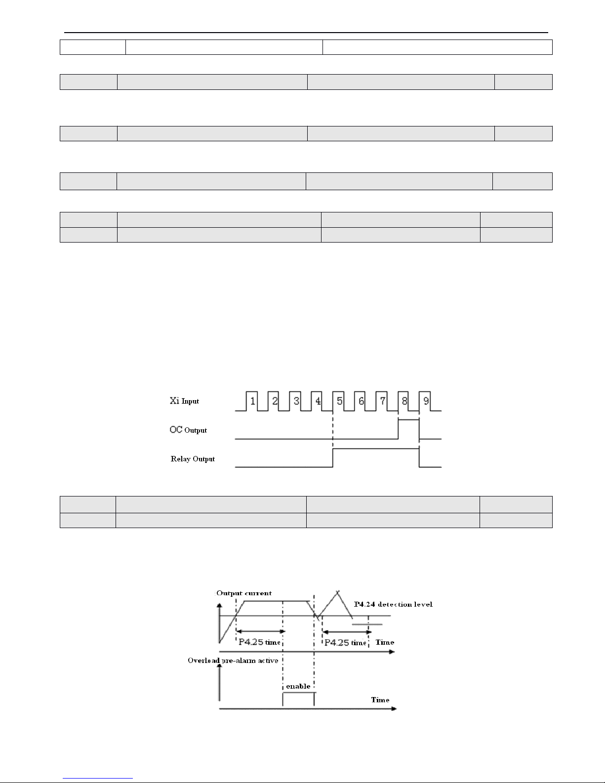
V5 series inverter
75
As to the analog output of AO, you can adjust the output gain to change the measuring range or calibrate the meter.
0
0
0
0 : 4
4
4
4 ~ 20mA
20mA
20mA
20mA
1
1
1
1 : 0
0
0
0 ~ 10V
10V
10V
10V
Refer to Table 4-7 for function selection of DO output terminal .
This parameter defines the max output frequency of DO terminal .
P4.22
,
P4.23 are the additional definition of N o.12,13 function s in table 4-6 .
Preset counting value arriving: It defines after Xi receives the relay or OC (bi-direction open-collector output terminal) will
output a signal.
For example: as shown in Fig. 4-28
,
when the eighth pulse signal is received
by
terminal Xi, OC outputs an indicating signal
and F7.33=8 at this time .
Mid counting value arriving: When Xi receives the number of pulse F7.34, OC or the relay will output a signal which will
last until preset counting value arrives.
As shown in Fig. 4-28
,
when Xi receives the 5th pulse, t he realy outputs an indication signal. It lasts until X1 receives the
8th pulse. At this time,P4.23
=5.The mid counting value will be disabled if it is bigger than preset counting value .
Fig.
Fig.
Fig.
Fig. 4
4
4
4 — 28
28
28
28 Preset
Preset
Preset
Preset counting
counting
counting
counting value
value
value
value arriving
arriving
arriving
arriving and
and
and
and Mid
Mid
Mid
Mid counting
counting
counting
counting value
value
value
value arriving
arriving
arriving
arriving
If output current over the detecting level setbyP4.24 continuously ( Actual detecting current level = P4.24 × inverter’s rate
d
cur r ent
) ,
Bi-direction open-collector will output available signal after the delay time set
by
P4.25(refer to Fig.4-29 and
P4.11 for details) .
Fig.
Fig.
Fig.
Fig. 4-29
4-29
4-29
4-29 Overload
Overload
Overload
Overload pre-alarm
pre-alarm
pre-alarm
pre-alarm
7
CI
0~10V/4~20mA
P4.19
P4.19
P4.19
P4.19
AO
AO
AO
AO output
output
output
output mode
mode
mode
mode
Range
Range
Range
Range : 0
0
0
0 、 1
1
1
1
1
1
1
1
P4.20
P4.20
P4.20
P4.20
DO
DO
DO
DO output
output
output
output terminal
terminal
terminal
terminal
Range
Range
Range
Range : 0
0
0
0 ~ 7
7
7
7
0
0
0
0
P4.21
P4.21
P4.21
P4.21
DO
DO
DO
DO max
max
max
max pulse
pulse
pulse
pulse output
output
output
output frequency
frequency
frequency
frequency
Range
Range
Range
Range : 0.1
0.1
0.1
0.1 ~ 20.0
20.0
20.0
20.0 ( max
max
max
max 20K
20K
20K
20K )
10.0K
10.0K
10.0K
10.0K
P4.22
P4.22
P4.22
P4.22
Preset
Preset
Preset
Preset counting
counting
counting
counting value
value
value
value arriving
arriving
arriving
arriving
Range
Range
Range
Range : P4.23
P4.23
P4.23
P4.23 ~ 9999
9999
9999
9999
0
0
0
0
P4.23
P4.23
P4.23
P4.23
Mid
Mid
Mid
Mid counting
counting
counting
counting value
value
value
value arriving
arriving
arriving
arriving
Range
Range
Range
Range : 0
0
0
0 ~ P4.22
P4.22
P4.22
P4.22
0
0
0
0
P4.24
P4.24
P4.24
P4.24
Overload
Overload
Overload
Overload pre-alarm
pre-alarm
pre-alarm
pre-alarm detection
detection
detection
detection level
level
level
level
Range
Range
Range
Range : 20
20
20
20 - 200(
200(
200(
200( % )
)
)
)
130(%)
130(%)
130(%)
130(%)
P4.25
P4.25
P4.25
P4.25
Overload
Overload
Overload
Overload pre-alarm
pre-alarm
pre-alarm
pre-alarm delay
delay
delay
delay time
time
time
time
Range
Range
Range
Range : 0.0
0.0
0.0
0.0 - 20.0S
20.0S
20.0S
20.0S
5.0S
5.0S
5.0S
5.0S
Page 82
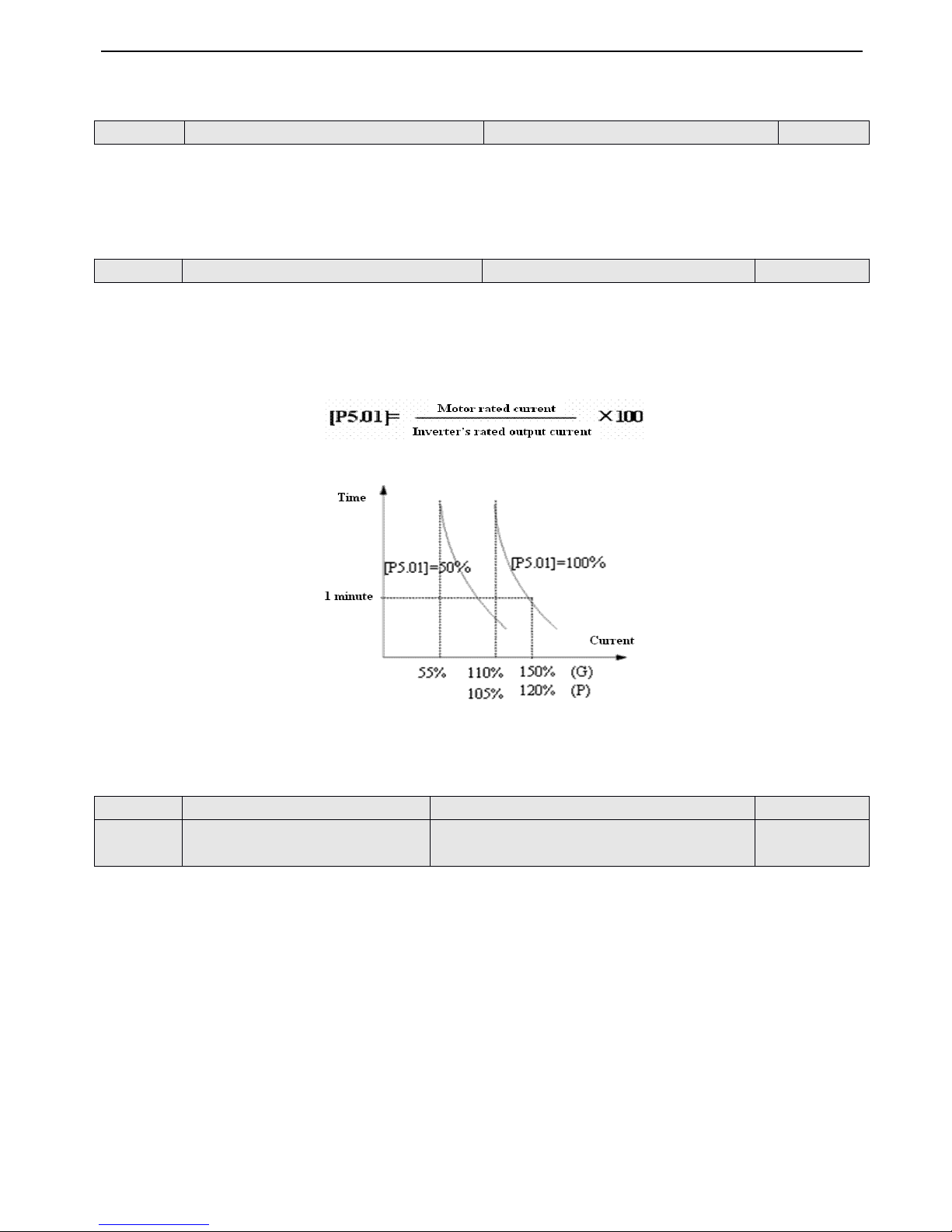
V5 series inverter
76
4-2-6
4-2-6
4-2-6
4-2-6
.
.
.
.
Protective
Protective
Protective
Protective function
function
function
function parameters
parameters
parameters
parameters ( Group
Group
Group
Group P5
P5
P5
P5 )
This parameter defines the protection mode when overload or overheat occurs.
0
0
0
0 :
Inverter
Inverter
Inverter
Inverter
locking
locking
locking
locking output
output
output
output.When
overload or
overheat occur s,inverter will
lock output
and
the
motor
will
coast-to-stop.
1
1
1
1 : Disabled
Disabled
Disabled
Disabled
.
.
.
.Motor will
be without
overload
protection
and
inverter
will
do
the overload
protection
for the motor.(Cautions
to
using)
This parmeter is used to set sensitivity of thermal relayprotection from inverter to overload. When the output current value
of load motor can not match the rated current of the inverter, correct thermal protection can be realized
by
setting this
parameter, as shown in Fig.4-30 .
Use the following coefficient to ca l culate .
Fig.
Fig.
Fig.
Fig. 4-30
4-30
4-30
4-30 Thermal
Thermal
Thermal
Thermal relay
relay
relay
relay protection
protection
protection
protection
Note
Note
Note
Note
: When one inverter run with multi-motors, inverter’s
thermal
relay
protection
will
be
disabled. Therefore,
please
install
thermal
relayinthe wire
end
of each motortoprotect
motor more e
fficient
ly .
0
0
0
0 : Prohitit
Prohitit
Prohitit
Prohitit
1
1
1
1 : Permit
Permit
Permit
Permit
During deceleration, the motor’s decelerate rate may be lower than that of inverter’s output frequency due to the load inertia.
At this time, the motor will feed back the energyto the drive, resulting in the voltage rise on the inverter 's DC bus. If no
measures taken, the inverter will trip due to over voltage.
During the deceleration, the inverter detects the bus voltage and compares it with the over voltage point at stall defined
by
P5.03
.
If the bus voltage exceeds the stall overvoltage point, the inverter will stop reducing its output frequency. When the
bus voltage become s lower than the point, the deceleration continues, as shown in Fig.4-31.
P5.00
P5.00
P5.00
P5.00
Motor
Motor
Motor
Motor overload
overload
overload
overload protection
protection
protection
protection mode
mode
mode
mode selection
selection
selection
selection
Range
Range
Range
Range : 0
0
0
0 ,
,
,
, 1
1
1
1
0
0
0
0
P5.01
P5.01
P5.01
P5.01
Motor
Motor
Motor
Motor
’
’
’
’
s
s
s
s overload
overload
overload
overload protection
protection
protection
protection coefficient
coefficient
coefficient
coefficient
Range
Range
Range
Range : 20(%)
20(%)
20(%)
20(%) - 120(%)
120(%)
120(%)
120(%)
100(%)
100(%)
100(%)
100(%)
P5.02
P5.02
P5.02
P5.02
Protection
Protection
Protection
Protection of
of
of
of over
over
over
over load
load
load
load at
at
at
at stall
stall
stall
stall
Range
Range
Range
Range : 0
0
0
0 ,
,
,
, 1
1
1
1
1
1
1
1
P5.03
P5.03
P5.03
P5.03
Over
Over
Over
Over voltage
voltage
voltage
voltage point
point
point
point at
at
at
at stall
stall
stall
stall
Range
Range
Range
Range : 380V
380V
380V
380V : 120
120
120
120 ~ 150(%)
150(%)
150(%)
150(%)
220V
220V
220V
220V : 110
110
110
110 ~ 130(%)
130(%)
130(%)
130(%)
140(%)
140(%)
140(%)
140(%)
120(%)
120(%)
120(%)
120(%)
Page 83
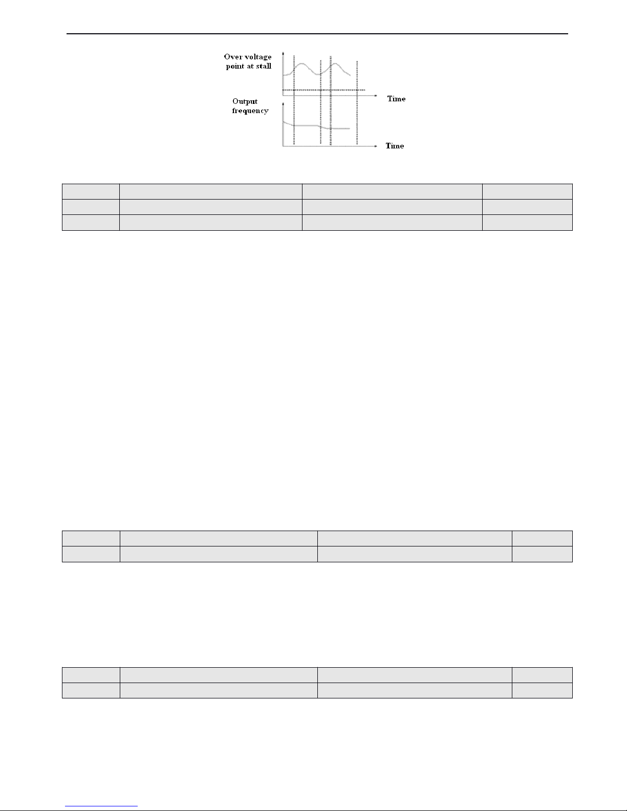
V5 series inverter
77
Fig.
Fig.
Fig.
Fig. 4-31
4-31
4-31
4-31 Over
Over
Over
Over voltage
voltage
voltage
voltage function
function
function
function
Auto current limiting function is used to limit the load current smaller than the value defined
by
P0.54 in real time.
Therefore the inverter will not trip due to surge over-current. This function is especially useful for the applications with big
load inertia or big change of load.
Auto current limiting threshold (P5.04) defines the threshold of auto current limiting. The range of i t is a percentage of the
inverter’s rated current.
Frequency decrease rate when current limiting (P5.05) defines the rate of output frequency
wh
en the inverter is in auto
current limiting status.
If the decrease rate is set too small, auto current limiting status may not be switched and overload fault may occur. If it is set
too big, the frequency will change too sharply and th us the inverter may be in generating status for long time, which may
result in overvoltage protection.
Auto current limiting function is always enabled in Acc or Dec process. Whether it is enabled in constant speed operating
process is decided
by
auto current limiting selection (P5.06).
P5.06 = 0, Auto current limiting function is disabled in constant speed operating process;
F 5.06 = 1, Auto current limiting function is enabled in constant speed operating process;
In auto current limiting process, the inverter’s output frequency may change; therefore, when the inverter’s output frequency
is required to be stable,this function is not recom m ended .
P5.07
P5.07
P5.07
P5.07 =
=
=
= 0
0
0
0 , Restart
Restart
Restart
Restart after
after
after
after instant
instant
instant
instant aneous
aneous
aneous
aneous power
power
power
power off
off
off
off is
is
is
is disabled.
disabled.
disabled.
disabled.
P5.07
P5.07
P5.07
P5.07 =
=
=
= 1
1
1
1 , Restart
Restart
Restart
Restart after
after
after
after instanteaneous
instanteaneous
instanteaneous
instanteaneous power
power
power
power off
off
off
off is
is
is
is enabled.
enabled.
enabled.
enabled.
If instantaneous powe off ( E-11 displayed in inverter’s LED ) occurs when inverter is in running status, after repower ing
,
it
will detect speed automatically and then restart after the reference holding time (set
by
P5.08)
.
During the holding time of
restart, the inverter will not start even if you input running command, while if you input stop command, the inverter will
stop detecting and restart ing
.
When the inverter is in running process, it may occur fault and s t op output
by
accident for overload fluctuating.To avoid the
paus e of the device, you can use auto reset times of fault. In the reseting process, inverter will restart with detecting function
.
If the inverter can not reset to running successfully in the reference times, fault protection will be enabled and output will
be stop ped .
Note
Note
Note
Note
:
:
:
:
(1) When use this function, make sure that it is permissible
by
device and there is no substantiality fault with inverter.
P5.04
P5.04
P5.04
P5.04
Auto current limiting threshold
Range
Range
Range
Range : 110
110
110
110 ~ 200(
200(
200(
200( % )
)
)
)
150(%)
150(%)
150(%)
150(%)
P5.05
P5.05
P5.05
P5.05
Frequeny decrease rate when current limiting
Range
Range
Range
Range : 0.00
0.00
0.00
0.00 ~ 99.99Hz
99.99Hz
99.99Hz
99.99Hz / S
S
S
S
10.00Hz/S
10.00Hz/S
10.00Hz/S
10.00Hz/S
P5.06
P5.06
P5.06
P5.06
Auto current limiting selection
Range
Range
Range
Range : 0
0
0
0 ,
,
,
, 1
1
1
1
1
1
1
1
P5.07
P5.07
P5.07
P5.07
Setting
Setting
Setting
Setting of
of
of
of restart
restart
restart
restart after
after
after
after power
power
power
power off
off
off
off
Range
Range
Range
Range : 0
0
0
0 ,
,
,
, 1
1
1
1
0
0
0
0
P5.08
P5.08
P5.08
P5.08
Holding
Holding
Holding
Holding time
time
time
time of
of
of
of restart
restart
restart
restart after
after
after
after power
power
power
power off
off
off
off
Range
Range
Range
Range : 0.0
0.0
0.0
0.0 ~ 10.0S
10.0S
10.0S
10.0S
0.5S
0.5S
0.5S
0.5S
P5.09
P5.09
P5.09
P5.09
Auto
Auto
Auto
Auto reset
reset
reset
reset times
times
times
times of
of
of
of fault
fault
fault
fault
Range
Range
Range
Range : 0
0
0
0 ~ 10
10
10
10
0
0
0
0
P5.10
P5.10
P5.10
P5.10
Auto
Auto
Auto
Auto reset interval
interval
interval
interval of
of
of
of fault
fault
fault
fault
Range
Range
Range
Range : 0.5
0.5
0.5
0.5 ~ 20.0S
20.0S
20.0S
20.0S
5.0S
5.0S
5.0S
5.0S
Page 84
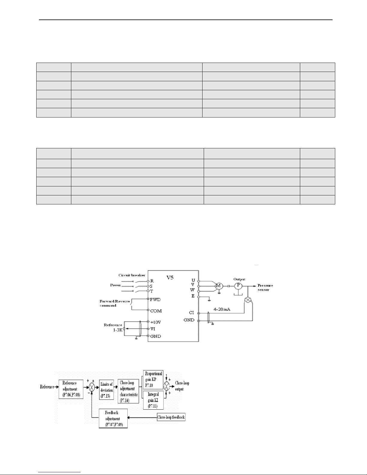
V5 series inverter
78
(2) This function is disabled with the fault protection caused
by
overload and overheat.
4-2-7
4-2-7
4-2-7
4-2-7
.
.
.
.
Fault
Fault
Fault
Fault recording
recording
recording
recording parameters
parameters
parameters
parameters ( Group
Group
Group
Group P6
P6
P6
P6 )
0
0
0
0 :
no
no
no
no
fault
fault
fault
fault
1
1
1
1 ~ 17
17
17
17 : E-01
E-01
E-01
E-01 ~ E-17
E-17
E-17
E-17 fault
fault
fault
fault , refer
refer
refer
refer
to
to
to
to
chapter
chapter
chapter
chapter 5
5
5
5 for
for
for
for fault
fault
fault
fault types.
types.
types.
types.
4-2-8
4-2-8
4-2-8
4-2-8 .Close-loop
.Close-loop
.Close-loop
.Close-loop control
control
control
control parameters
parameters
parameters
parameters (Group
(Group
(Group
(Group P7)
P7)
P7)
P7)
Analog feedback control system
Reference pressure is input via VI, and feedback value ( 4 ~ 20mA ) of pressure sensor is input to inverter via CI.Also, there
is an internal PI adjust or to form analog close-loop control system
,
as shown in Fig4-32.
Fig.
Fig.
Fig.
Fig. 4-32
4-32
4-32
4-32 Analog
Analog
Analog
Analog feedback
feedback
feedback
feedback control
control
control
control system
system
system
system with
with
with
with internal
internal
internal
internal PI
PI
PI
PI
Principle diagram of inverter’s internal PI is shown below:
Fig.
Fig.
Fig.
Fig. 4-33
4-33
4-33
4-33 PI
PI
PI
PI block
block
block
block diagram
diagram
diagram
diagram
Close-loop reference, feedback, limits of deviation, proportional and integral parameters which are as same as common PI
P6.00
P6.00
P6.00
P6.00
Previous
Previous
Previous
Previous fault
fault
fault
fault record
record
record
record
Range
Range
Range
Range : 0~23
0~23
0~23
0~23
0
0
0
0
P6.07
P6.07
P6.07
P6.07
2
2
2
2 latest
latest
latest
latest fault
fault
fault
fault record
record
record
record
Range
Range
Range
Range : 0~23
0~23
0~23
0~23
0
0
0
0
P6.08
P6.08
P6.08
P6.08
3
3
3
3 latest
latest
latest
latest fault
fault
fault
fault record
record
record
record
Range
Range
Range
Range : 0~23
0~23
0~23
0~23
0
0
0
0
P6.09
P6.09
P6.09
P6.09
4
4
4
4 latest
latest
latest
latest fault
fault
fault
fault record
record
record
record
Range
Range
Range
Range : 0~23
0~23
0~23
0~23
0
0
0
0
P6.10
P6.10
P6.10
P6.10
5
5
5
5 latest
latest
latest
latest fault
fault
fault
fault record
record
record
record
Range
Range
Range
Range : 0~23
0~23
0~23
0~23
0
0
0
0
P6.11
P6.11
P6.11
P6.11
6
6
6
6 latest
latest
latest
latest fault
fault
fault
fault record
record
record
record
Range
Range
Range
Range : 0~23
0~23
0~23
0~23
0
0
0
0
P6.01
P6.01
P6.01
P6.01
Output
Output
Output
Output frequency
frequency
frequency
frequency of
of
of
of previous
previous
previous
previous fault
fault
fault
fault
Range
Range
Range
Range : 0
0
0
0 ~ upper
upper
upper
upper limit
limit
limit
limit of
of
of
of frequency
frequency
frequency
frequency
0
0
0
0
P6.02
P6.02
P6.02
P6.02
Setting
Setting
Setting
Setting frequency
frequency
frequency
frequency of
of
of
of previous
previous
previous
previous fault
fault
fault
fault
Range
Range
Range
Range : 0
0
0
0 ~ upper
upper
upper
upper limit
limit
limit
limit of
of
of
of frequency
frequency
frequency
frequency
0
0
0
0
P6.03
P6.03
P6.03
P6.03
Output
Output
Output
Output current
current
current
current of
of
of
of previous
previous
previous
previous fault
fault
fault
fault
Range
Range
Range
Range : 0
0
0
0 ~ 999.9A
999.9A
999.9A
999.9A
0
0
0
0
P6.04
P6.04
P6.04
P6.04
Output
Output
Output
Output voltage
voltage
voltage
voltage of
of
of
of previous
previous
previous
previous fault
fault
fault
fault
Range
Range
Range
Range : 0
0
0
0 ~ 999V
999V
999V
999V
0
0
0
0
P6.05
P6.05
P6.05
P6.05
DC
DC
DC
DC injectiong
injectiong
injectiong
injectiong bus
bus
bus
bus voltage
voltage
voltage
voltage of
of
of
of previous
previous
previous
previous fault
fault
fault
fault
Range
Range
Range
Range : 0
0
0
0 ~ 800V
800V
800V
800V
0
0
0
0
P6.06
P6.06
P6.06
P6.06
Module
Module
Module
Module temperature
temperature
temperature
temperature of
of
of
of previous
previous
previous
previous fault
fault
fault
fault
Range
Range
Range
Range : 0
0
0
0 ~ 100
100
100
100
0
0
0
0
Page 85
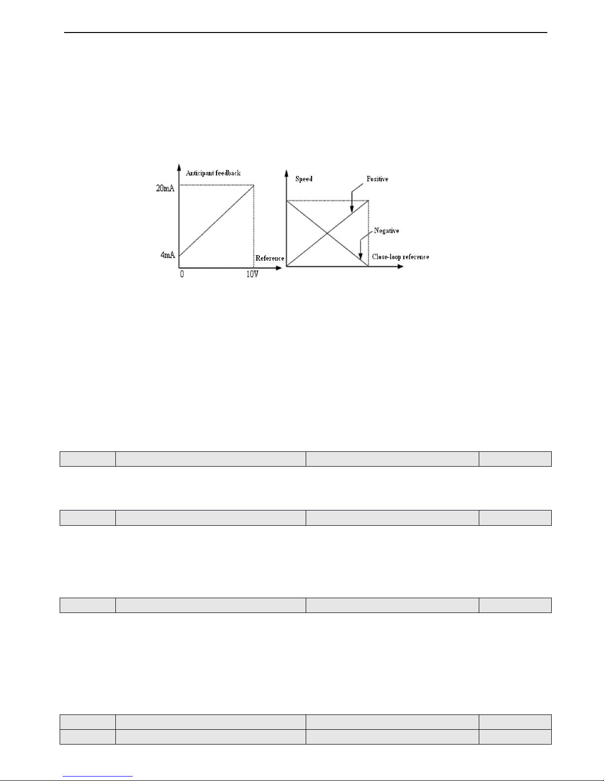
V5 series inverter
79
adjustment are defined in P7.01~P7.11.T he relationship between reference and feedback are shown in Fig4-34
,
thereinto,
10V corresponds to 100% of reference and 20mA corresponds to 100% of feedback.
The aim of reference adjustment and feedback adjustment is to confirm the corresponding relationship and dimension of
unification
,
as shown in Fig.4-33.
If the motor’s speed is required to increases with the reference speed, this kind of control characteristic is called positive
characteristic. On the contrary, i f the motor speed is required to decrease when the reference value increases, this control
characteristic is called negative characteristic.
The two close-loop characteristic can be setbyP7.14, as shown in Fig4-35 .
Fig.
Fig.
Fig.
Fig. 4-34
4-34
4-34
4-34 Reference
Reference
Reference
Reference and
and
and
and Fig.4-35
Fig.4-35
Fig.4-35
Fig.4-35 Close-loop
Close-loop
Close-loop
Close-loop adjustment
adjustment
adjustment
adjustment
anticipant
anticipant
anticipant
anticipant feedback
feedback
feedback
feedback characteristic
characteristic
characteristic
characteristic diagram
diagram
diagram
diagram
After conforming the system, the pro cedure of setting close-loop parameters is shown below:
(1) Confirm the close-loop reference and feedback channel (P7.01
,
P7.02) .
(2) The relationship between close-loop reference and feedback value (P7.06~P7.09) should be defined for close-loop
control.
(3) If reference and required motor’s speed is opposite, please set close-loop characteristic as negative to confirm close-loop
adjustment characteristic ( P7.14=1), as shown in Fig4-35.
(4) Set the function of close-loop preset frequency (P7.16 ~ P7.17) .
(5) Set close-loop filter time, sam pling cycle
T,
limits of deviation and gain coefficient (P7.03
,
P7.04
,
P7.12
,
P7.13) .
0
0
0
0 : Close-loop
Close-loop
Close-loop
Close-loop control
control
control
control is
is
is
is disabled
disabled
disabled
disabled
1
1
1
1 : PI
PI
PI
PI close-loop
close-loop
close-loop
close-loop control
control
control
control is
is
is
is enabled
enabled
enabled
enabled
0
0
0
0 : Digit
Digit
Digit
Digit input
input
input
input
1
1
1
1 : VI
VI
VI
VI (
(
(
( 0
0
0
0 - 10V
10V
10V
10V )
)
)
)
2
2
2
2
:
:
:
:
CI
CI
CI
CI
.
.
.
.
0~10V voltage or 4~20mA current reference,for speed close-loop, analog reference of 10V corresponds to the
synchronized speed of the motor’s max output frequency .
0
0
0
0 : VI
VI
VI
VI (
(
(
( 0
0
0
0 - 10V
10V
10V
10V
)
)
)
)
1
1
1
1 : CI
CI
CI
CI
2
2
2
2 : VI
VI
VI
VI +CI
+CI
+CI
+CI
3
3
3
3 : VI
VI
VI
VI -
-
-
- CI
CI
CI
CI
4
4
4
4 : Min
Min
Min
Min {
VI
VI
VI
VI
,
,
,
, CI
CI
CI
CI }
5
5
5
5 : Max
Max
Max
Max {
VI
VI
VI
VI
,
,
,
, CI
CI
CI
CI }
P7.00
P7.00
P7.00
P7.00
Close-loop
Close-loop
Close-loop
Close-loop function
function
function
function selection
selection
selection
selection
Range
Range
Range
Range : 0
0
0
0 ,
,
,
, 1
1
1
1
0
0
0
0
P7.01
P7.01
P7.01
P7.01
Reference
Reference
Reference
Reference channel
channel
channel
channel selection
selection
selection
selection
Range
Range
Range
Range : 0
0
0
0 ,
,
,
, 1
1
1
1 ,
,
,
, 2
2
2
2
1
1
1
1
P7.02
P7.02
P7.02
P7.02
Feedback channel selection
Range
Range
Range
Range : 0~6
0~6
0~6
0~6
1
1
1
1
P7.03
P7.03
P7.03
P7.03
R
R
R
R eference
eference
eference
eference filter
filter
filter
filter
Range
Range
Range
Range : 0.01~50.00S
0.01~50.00S
0.01~50.00S
0.01~50.00S
0.50S
0.50S
0.50S
0.50S
P7.04
P7.04
P7.04
P7.04
Feedback
Feedback
Feedback
Feedback filter
filter
filter
filter
Range
Range
Range
Range : 0.01~50.00S
0.01~50.00S
0.01~50.00S
0.01~50.00S
0.50S
0.50S
0.50S
0.50S
Page 86
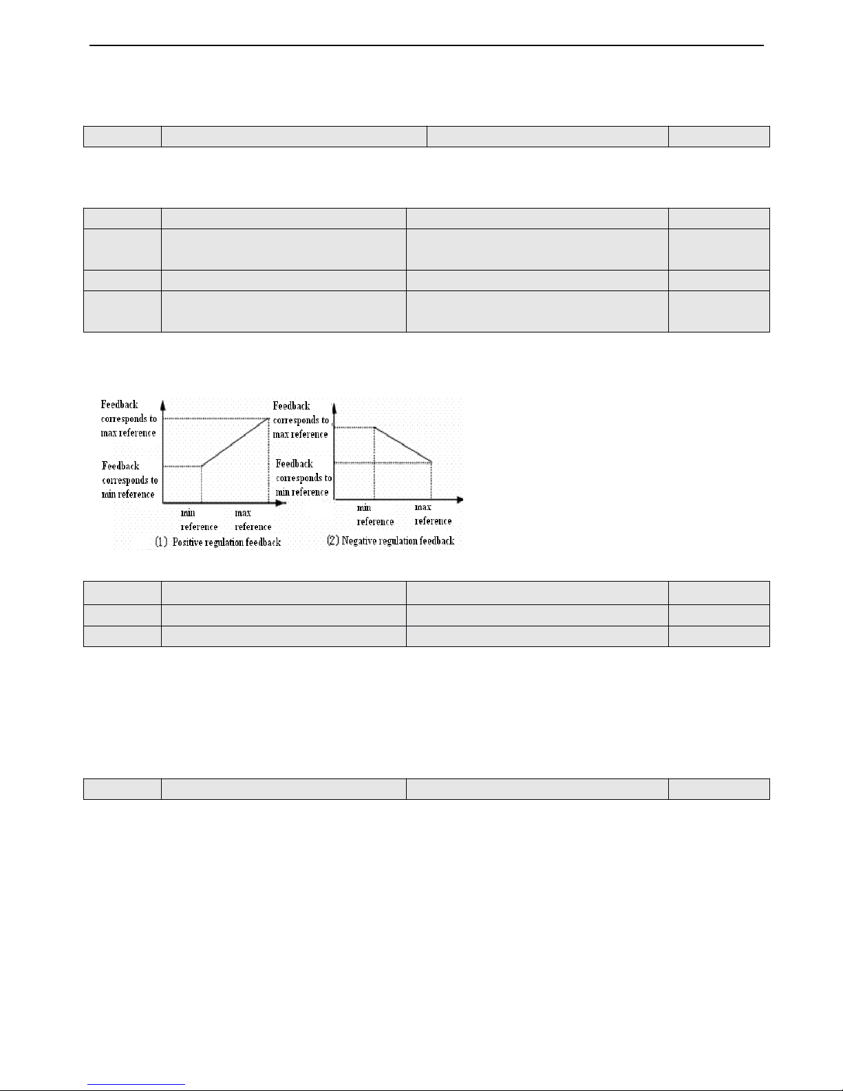
V5 series inverter
80
Both
the external
reference signal
and
feedback signal have interferences,w
hile
these
can
be
filtered by
setting
the
time constant
of
filter
(P7.03
and
P7.04), the
longer
the
filter
time, the better the immunity
capability,
but the
slower
the
response; on
the
contrary,
the shorter the
filter
time,the
worse
the immunity
capability,but the
quicker
the
response.
If
P7.01=0,the value setbyP7.05
will
be
as the
reference of close-loop control system.Therefore,
you
can modify the value
of
P7.05
to
changeifvia operation
keyboard or serial
port.
P7.06 ~ P7.09 define the relationship curve of analog close-loop reference and expecti ng feedba ck. The reference value is
the percentage of real value of feedback corresponding to benchmark value ( 10V or 20mA ), a s shown in Fig. 4 - 36 .
Fig.
Fig.
Fig.
Fig. 4-36
4-36
4-36
4-36 reference
reference
reference
reference and
and
and
and feedback
feedback
feedback
feedback curve
curve
curve
curve
The bigger the proportion gain
KP,
the quicker the response, while too bigger of it may lead to surge easily.
As only with proportiaon gian
KP,
deviation can not be eliminated, integral gain KI can be used to to form PI control to
eliminate the deviation.The bigge r of the Ki,the quicker the response of changing deviation,while too big of the Ki may lead
to surge easily.
Sampling cycle T is the sampling cycle of feedback value. PI regulator ca l culate once in every sampling clcle, the longer the
cycle,the slower the response.
The
max
deviation value
of
close-loop referenceisshown
in Fig.4-37, if
the feedback valueiswithinthis
range,
PI regulator
will
stop
operation.
This function
is
useful
to
improve
accuracy andstab
ility
of
the
system.
P7.05
P7.05
P7.05
P7.05
Set
Set
Set
Set reference
reference
reference
reference in
in
in
in digital
digital
digital
digital mode
mode
mode
mode
Range
Range
Range
Range : 0.00
0.00
0.00
0.00 - 10.00V
10.00V
10.00V
10.00V
0.00V
0.00V
0.00V
0.00V
P7.06
P7.06
P7.06
P7.06
Min
Min
Min
Min reference
reference
reference
reference
Range
Range
Range
Range : 0.0
0.0
0.0
0.0 - Max
Max
Max
Max reference
reference
reference
reference
0.0
0.0
0.0
0.0 %
P7.07
P7.07
P7.07
P7.07
Feedback
Feedback
Feedback
Feedback value
value
value
value corresponding
corresponding
corresponding
corresponding to
to
to
to min
min
min
min
reference
reference
reference
reference
Range
Range
Range
Range : 0.0
0.0
0.0
0.0 - 100.0(%)
100.0(%)
100.0(%)
100.0(%)
0.0
0.0
0.0
0.0 %
P7.08
P7.08
P7.08
P7.08
Max
Max
Max
Max reference
reference
reference
reference
Range
Range
Range
Range : min
min
min
min reference
reference
reference
reference -100.0(
-100.0(
-100.0(
-100.0( % )
)
)
)
100.0%
100.0%
100.0%
100.0%
P7.09
P7.09
P7.09
P7.09
Feedback
Feedback
Feedback
Feedback value
value
value
value corresponding
corresponding
corresponding
corresponding to
to
to
to max
max
max
max
reference
reference
reference
reference
Range
Range
Range
Range : 0.0%
0.0%
0.0%
0.0% - 100.0(
100.0(
100.0(
100.0( % )
)
)
)
100.0%
100.0%
100.0%
100.0%
P7.10
P7.10
P7.10
P7.10
Proportion
Proportion
Proportion
Proportion al
al
al
al gain
gain
gain
gain KP
KP
KP
KP
Range
Range
Range
Range : 0.000~9.999
0.000~9.999
0.000~9.999
0.000~9.999
0.050
0.050
0.050
0.050
P7.11
P7.11
P7.11
P7.11
Integral
Integral
Integral
Integral gain
gain
gain
gain KI
KI
KI
KI
Range
Range
Range
Range : 0.000~9.999
0.000~9.999
0.000~9.999
0.000~9.999
0.050
0.050
0.050
0.050
P7.12
P7.12
P7.12
P7.12
Sampling
Sampling
Sampling
Sampling cycle
cycle
cycle
cycle T
T
T
T
Range
Range
Range
Range : 0.01
0.01
0.01
0.01 - 10.00S
10.00S
10.00S
10.00S
1.00S
1.00S
1.00S
1.00S
P7.13
P7.13
P7.13
P7.13
Limits
Limits
Limits
Limits of
of
of
of deviation
deviation
deviation
deviation
Range
Range
Range
Range : 0.0
0.0
0.0
0.0 - 20.0(
20.0(
20.0(
20.0( % )
)
)
)
2.0(
2.0(
2.0(
2.0( % )
)
)
)
Page 87
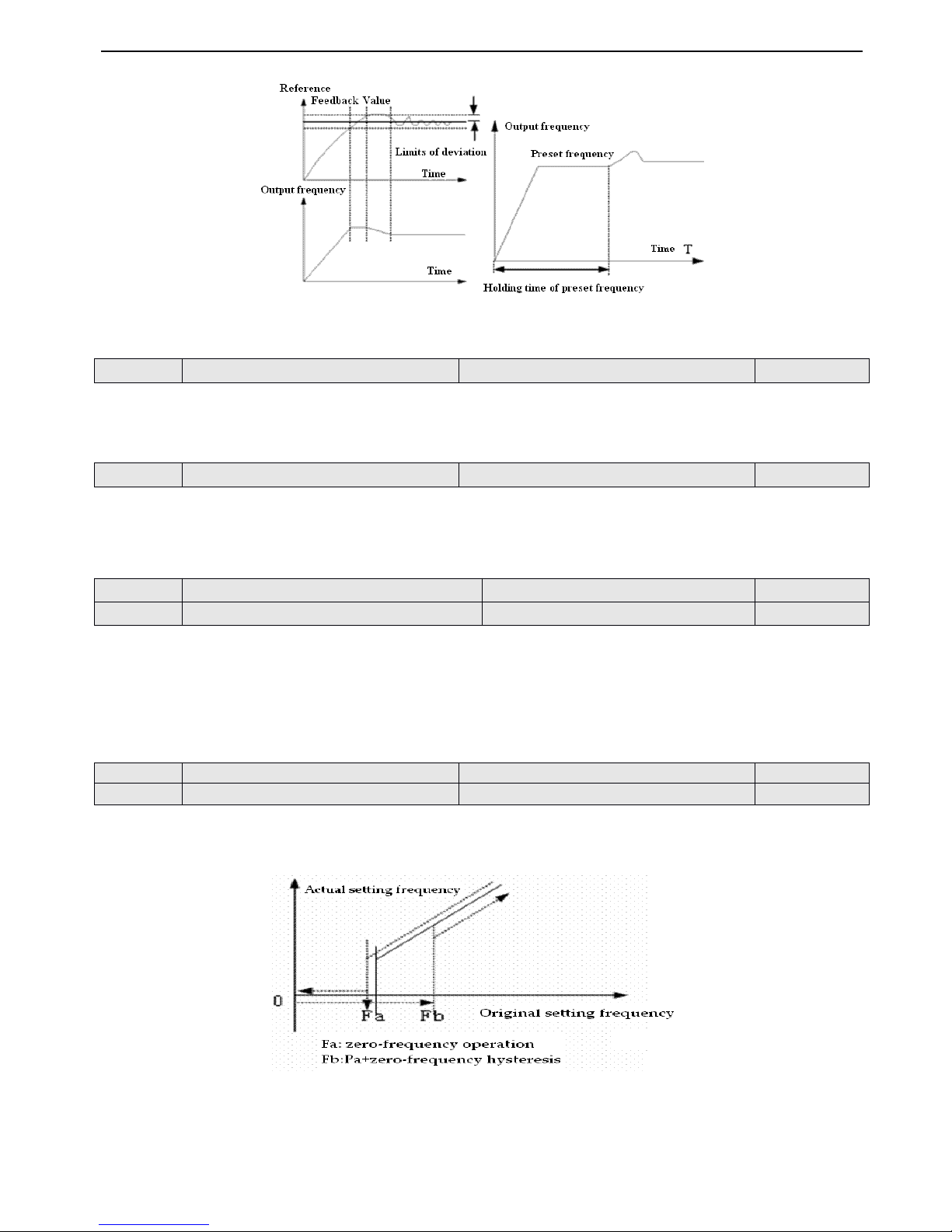
V5 series inverter
81
Fig.
Fig.
Fig.
Fig. 4-37
4-37
4-37
4-37 Limits
Limits
Limits
Limits of
of
of
of deviation
deviation
deviation
deviation Fig.
Fig.
Fig.
Fig. 4-38
4-38
4-38
4-38 close-loop
close-loop
close-loop
close-loop preset
preset
preset
preset frequency
frequency
frequency
frequency
0:
0:
0:
0: Positive
Positive
Positive
Positive
.
.
.
. When the reference increases, it will be enabled when the motor speed increase.
1:
1:
1:
1:
Negative
Negative
Negative
Negative .
.
.
. When the reference increases, it will be enabled when the motor speed reduces
Note : Define the relationship of reference and speed.
0 : Stop integral adjustment selection when the frequency reaches upper limit or lower limit s
1 : Continue the integral adjustment selection when the frequency reaches hig h limit or lower limit s
For the system need quick response, can cel the continuouse integral adjustment is recommended.
This function can make the close-loop adjustment enter stable stage quickly.
When
the
close-loop
starts,
thefrequency will accelerate
to
the preset value setbyP7.16
according
to Acc
time
and
the
inverter
will
running wit h
this freuquency
in
the
holding time
set
by
P7.17,
then running according
to
close-lood
character,asshown
in
Fig4-38.
Note
Note
Note
Note : If the function of close-loop preset frequency is not needed, you can set the preset frequency and holding time as 0.
The two function parameter is used for setting PI threshold and hysteresis of zero-frequency operation
.
If you set the frequency as0Hz,PI threshold of zero-frequency operation will be disa b led.
Fig.
Fig.
Fig.
Fig. 4-39
4-39
4-39
4-39 zero-frequency
zero-frequency
zero-frequency
zero-frequency hysteresis
hysteresis
hysteresis
hysteresis
As shown in Fig. 4-39
Start process :
P7.14
P7.14
P7.14
P7.14
Close
Close
Close
Close loop
loop
loop
loop adjustment
adjustment
adjustment
adjustment characteristic
characteristic
characteristic
characteristic
Range
Range
Range
Range : 0
0
0
0 ,
,
,
, 1
1
1
1
0
0
0
0
P7.15
P7.15
P7.15
P7.15
Integral
Integral
Integral
Integral adjustment
adjustment
adjustment
adjustment selection
selection
selection
selection
Range
Range
Range
Range : 0
0
0
0 ,
,
,
, 1
1
1
1
0
0
0
0
P7.16
P7.16
P7.16
P7.16
Close-loop
Close-loop
Close-loop
Close-loop preset
preset
preset
preset frequency
frequency
frequency
frequency
Range
Range
Range
Range : 0
0
0
0 - upper
upper
upper
upper limit
limit
limit
limit of
of
of
of frequency
frequency
frequency
frequency
0.00Hz
0.00Hz
0.00Hz
0.00Hz
P7.17
P7.17
P7.17
P7.17
Holding
Holding
Holding
Holding time
time
time
time of
of
of
of close-loop
close-loop
close-loop
close-loop preset
preset
preset
preset frequency
frequency
frequency
frequency
Range
Range
Range
Range : 0.0
0.0
0.0
0.0 - 250.0S
250.0S
250.0S
250.0S
0.1S
0.1S
0.1S
0.1S
P7.18
P7.18
P7.18
P7.18
PI
PI
PI
PI Threshold
Threshold
Threshold
Threshold of
of
of
of zero-frequency
zero-frequency
zero-frequency
zero-frequency operation
operation
operation
operation
Range
Range
Range
Range : 0.00
0.00
0.00
0.00 - 500.0Hz
500.0Hz
500.0Hz
500.0Hz
0.01Hz
0.01Hz
0.01Hz
0.01Hz
P7.19
P7.19
P7.19
P7.19
PI
PI
PI
PI hysteresis
hysteresis
hysteresis
hysteresis of
of
of
of zero-frequency
zero-frequency
zero-frequency
zero-frequency operation
operation
operation
operation
Range
Range
Range
Range : 0.00
0.00
0.00
0.00 - 500.0Hz
500.0Hz
500.0Hz
500.0Hz
0.01Hz
0.01Hz
0.01Hz
0.01Hz
Page 88
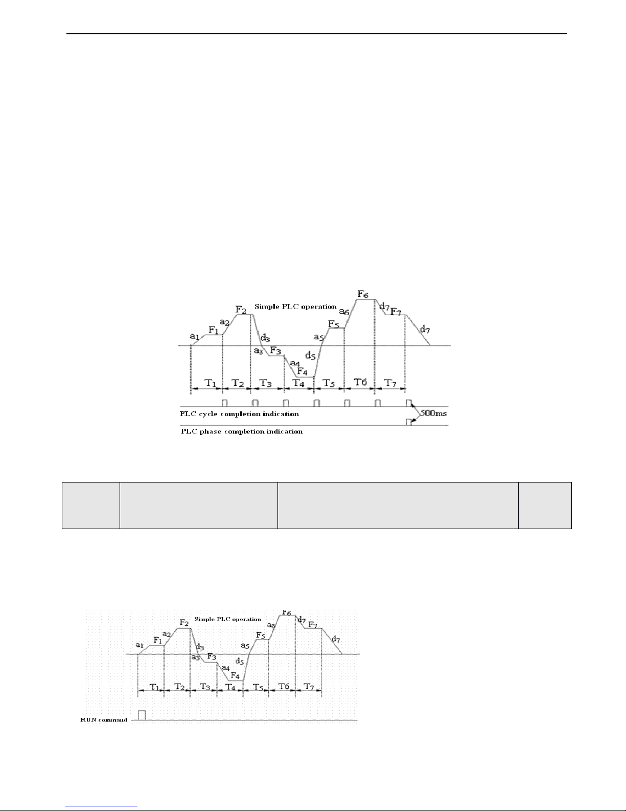
V5 series inverter
82
After start command is set out, the motor will start and accelerate to the frequency in the Acc time until the setting frequency
reach or exceeds the certain value
Fb
.
Stop process :
The inverter will not stop immediately if the setting frequency is lower than Fb, only when the setting frequency reach Fa,
the inverter will stop output.
Fa points to zero-frequency threshold which is defined
by
P7.18, the value among Fb-Fa point to zero-frequency hysteresis
which is defined
byP7.19
.
This function can enable the inverter to enter domant state so as to save energy, besides, the inverter will not start at the
threshold of zero-frequency operation if the hysteresis is set properly.
4-2-9
4-2-9
4-2-9
4-2-9
.
.
.
.
Simple
Simple
Simple
Simple PLC
PLC
PLC
PLC operation
operation
operation
operation parameters
parameters
parameters
parameters .
.
.
. ( Group
Group
Group
Group P8
P8
P8
P8 )
Simple PLC function can enable the inverter to change its operating frequency and directions automatically to satisfy the
manufacturing requirements,as shown in Fig4-40.
Fig.
Fig.
Fig.
Fig. 4-40
4-40
4-40
4-40 Simple
Simple
Simple
Simple PLC
PLC
PLC
PLC diagram
diagram
diagram
diagram
In Fig,4-40 , a1~a7、 d1~d7are the Acc/Dec time of different stages and they are setbyAcc/Dec time parameters P0.17 , P0.18
and P3.14 ~
P3.2,F1~F7、 T1~T7are the running frequency and running time and they are setbyP8.01 ~ P8.14 .
Unit
Unit
Unit
Unit
’
’
’
’
s
s
s
s place
place
place
place of
of
of
of LED
LED
LED
LED : PLC operation mode selection
0
0
0
0 : Disabled.
Disabled.
Disabled.
Disabled.
1
1
1
1:Stop
Stop
Stop
Stop after
after
after
after operating
operating
operating
operating for
for
for
for one
one
one
one cycle.
cycle.
cycle.
cycle. As
As
As
As shown
shown
shown
shown in
in
in
in Fig.4-41
Fig.4-41
Fig.4-41
Fig.4-41
.
If inverter stop after single cycle operation
,
running comma nd
should be give once again to start the inverter.
Fig.
Fig.
Fig.
Fig. 4-41
4-41
4-41
4-41 PLC
PLC
PLC
PLC stop
stop
stop
stop mode
mode
mode
mode after
after
after
after single
single
single
single cycle
cycle
cycle
cycle of
of
of
of operation
operation
operation
operation
2
2
2
2:Holding at the final value after single cycle of operation
.
.
.
.
A s shown in Fig. 4-42
,
Inverter will keep the running frequenc
y,
direction of the last setting automatically after single cycle is completed,then it will stop with the reference Dec time if stop
P8.00
P8.00
P8.00
P8.00
Simple
Simple
Simple
Simple PLC
PLC
PLC
PLC operation
operation
operation
operation mode
mode
mode
mode selection
selection
selection
selection
Range
Range
Range
Range (LED)
(LED)
(LED)
(LED) :
Unit
Unit
Unit
Unit
’
’
’
’
s
s
s
s place
place
place
place : 0~3
0~3
0~3
0~3 ;
Ten
Ten
Ten
Ten
’
’
’
’
s
s
s
s place
place
place
place : 0
0
0
0 ,
,
,
, 1
1
1
1 ;
Hundred
Hundred
Hundred
Hundred
’
’
’
’
s
s
s
s place:
place:
place:
place: 0
0
0
0 ,
,
,
, 1
1
1
1 ;
Thousand
Thousand
Thousand
Thousand
’
’
’
’
s
s
s
s place
place
place
place : 0
0
0
0 ,
,
,
, 1
1
1
1
0000
0000
0000
0000
Page 89
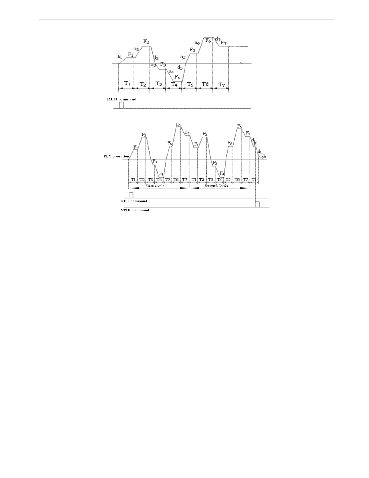
V5 series inverter
83
command is input.
Fig.
Fig.
Fig.
Fig. 4-42
4-42
4-42
4-42 PLC
PLC
PLC
PLC holding
holding
holding
holding mode
mode
mode
mode after
after
after
after single
single
single
single cycle
cycle
cycle
cycle
Fig.
Fig.
Fig.
Fig. 4-43
4-43
4-43
4-43 PLC
PLC
PLC
PLC operate
operate
operate
operate conti
conti
conti
conti nuously
nuously
nuously
nuously mode
mode
mode
mode
3
3
3
3
:
:
:
:
Operate
Operate
Operate
Operate continuously
continuously
continuously
continuously
.
.
.
.
As in Fig. 4-43 , inverter start next cycle automatically after operating for one cycle,it will stop
until stop command is input.
Ten
Ten
Ten
Ten
’
’
’
’
s
s
s
s place:
place:
place:
place:
R estarting mode after stopping
0 : Run again for stage 1
1 : Continue to run from the stopping stage
Hundred
Hundred
Hundred
Hundred
’
’
’
’
s
s
s
s place
place
place
place :
Save at power off
0 : Not saving
1 : Save the time and frequency at power off
Thousand
Thousand
Thousand
Thousand
’
’
’
’
s
s
s
s place
place
place
place : Selecting the unit of time
0: second
1: minute
Ten
Ten
Ten
Ten
’
’
’
’
s
s
s
s place
place
place
place of
of
of
of LED
LED
LED
LED : PLC restarting mode after stopping
0
0
0
0
:
:
:
:
Run again f rom stage 1
.
.
.
.
Inverter will start to run from stage
1
if the stop is caused
by
stop command, fault or power off.
1
1
1
1
:
:
:
:
Continue to run from the stopping stage
.
.
.
.
For the stop caused
by
stop command or fault, inverter will recorc the time in
current phase automatically, then restart to enter this stage with the same frequency and run continuously in the rest time, as
shown in Fig.4-44 .
Page 90
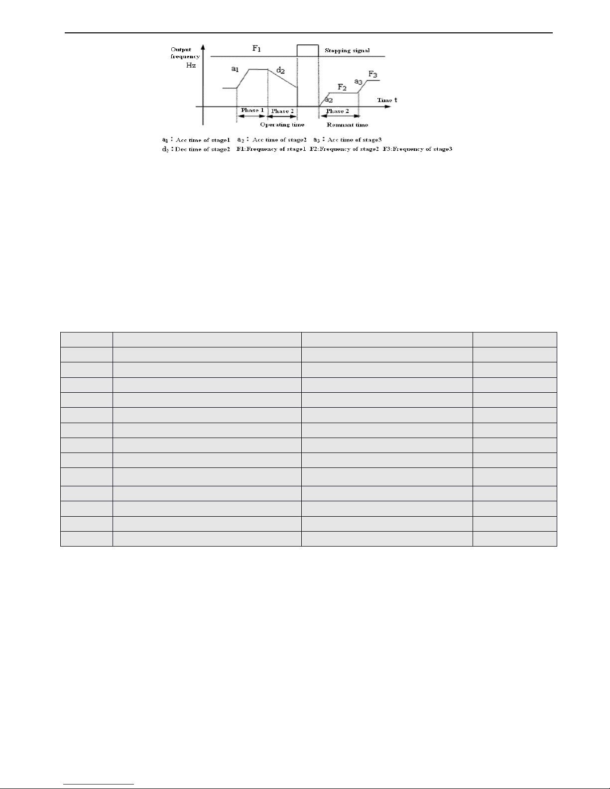
V5 series inverter
84
Fig.
Fig.
Fig.
Fig. 4-44
4-44
4-44
4-44 PLC
PLC
PLC
PLC start
start
start
start mode
mode
mode
mode 1
1
1
1
Ten
Ten
Ten
Ten
’
’
’
’
s
s
s
s place
place
place
place of
of
of
of LED
LED
LED
LED : Save at power off
0
0
0
0 : Not
Not
Not
Not saving.
saving.
saving.
saving. The inverter does not save the PLC operating status after power off and re start to operat e in first stage .
1
1
1
1:Save.
Save.
Save.
Save. Save the operating parameters of PLC operation after power off,including the operating stage, operating frequenc
y
and operating time. The inverter will continue to operate in the mode defined
by
the ten’s place.
Thousand
Thousand
Thousand
Thousand
’
’
’
’
s
s
s
s place
place
place
place of
of
of
of LED
LED
LED
LED : PLC running time
0
0
0
0 : second
second
second
second
1
1
1
1 : minute
minute
minute
minute
This unit only valid for the definition of PLC running time. The unit of Acc/Dec time durning PLC is running is set
by
P0.16 .
Note
Note
Note
Note : (1) This stage is invalid when the PLC running time is set as 0.
(2)
You
can control pause, invalidation, run and others for the PLC process via terminals, refer to group P4 for details.
F requency setup
0 : Multi i ( i = 1 ~ 7 )
1: Frequency is decide
by
P0.01
Ten’s place of LED : Operating direction selection
0 : Run forward
1 : Run reverse
2 : Decided
by
operating instructions
Hundred’s place of LED : Acc/Dec time selection
With the unit’s place, ten’s place and hundred’s place of LED, P8.01~P8.14 defined the running frequency, direction and
Acc/Dec time of PLC :
Unit
Unit
Unit
Unit
’
’
’
’
s
s
s
s place
place
place
place of
of
of
of LE
LE
LE
LE D:
0
0
0
0 : Multi-frequency
Multi-frequency
Multi-frequency
Multi-frequency i
i
i
i,i=1~7,defined
by
P3.26~P3.32 .
1
1
1
1 : Frequency
Frequency
Frequency
Frequency is
is
is
is set
set
set
set by
by
by
by P0.01
P0.01
P0.01
P0.01
Ten
Ten
Ten
Ten
’
’
’
’
s
s
s
s place
place
place
place of
of
of
of LED
LED
LED
LED : Operating direction selection
P8.01
P8.01
P8.01
P8.01
St
St
St
St age
age
age
age 1
1
1
1 setup
setup
setup
setup
Range
Range
Range
Range : 000
000
000
000 - 621
621
621
621
000
000
000
000
P8.02
P8.02
P8.02
P8.02
Operating
Operating
Operating
Operating time
time
time
time of
of
of
of stage
stage
stage
stage 1
1
1
1
Range
Range
Range
Range : 0.1
0.1
0.1
0.1 - 6000.0
6000.0
6000.0
6000.0
10.0
10.0
10.0
10.0
P8.03
P8.03
P8.03
P8.03
Stage
Stage
Stage
Stage 2
2
2
2 setup
setup
setup
setup
Range
Range
Range
Range : 000
000
000
000 - 621
621
621
621
000
000
000
000
P8.04
P8.04
P8.04
P8.04
Operating
Operating
Operating
Operating time
time
time
time of
of
of
of stage
stage
stage
stage 2
2
2
2
Range
Range
Range
Range : 0.1
0.1
0.1
0.1 - 6000.0
6000.0
6000.0
6000.0
10.0
10.0
10.0
10.0
P8.05
P8.05
P8.05
P8.05
Stage
Stage
Stage
Stage 3
3
3
3 setup
setup
setup
setup
Range
Range
Range
Range : 000
000
000
000 - 621
621
621
621
000
000
000
000
P8.06
P8.06
P8.06
P8.06
Operating
Operating
Operating
Operating time
time
time
time of
of
of
of stage
stage
stage
stage 3
3
3
3
Range
Range
Range
Range : 0.1
0.1
0.1
0.1 - 6000.0
6000.0
6000.0
6000.0
10.0
10.0
10.0
10.0
P8.07
P8.07
P8.07
P8.07
Stage
Stage
Stage
Stage 4
4
4
4 setup
setup
setup
setup
Range
Range
Range
Range : 000
000
000
000 - 621
621
621
621
000
000
000
000
P8.08
P8.08
P8.08
P8.08
Operating
Operating
Operating
Operating time
time
time
time of
of
of
of stage
stage
stage
stage 4
4
4
4
Range
Range
Range
Range : 0.1
0.1
0.1
0.1 - 6000.0
6000.0
6000.0
6000.0
10.0
10.0
10.0
10.0
P8.09
P8.09
P8.09
P8.09
Stage
Stage
Stage
Stage 5
5
5
5 setup
setup
setup
setup
Range
Range
Range
Range : 000
000
000
000 - 621
621
621
621
000
000
000
000
P8.10
P8.10
P8.10
P8.10
Operating
Operating
Operating
Operating time
time
time
time of
of
of
of stage
stage
stage
stage 5
5
5
5
Range
Range
Range
Range : 0.1
0.1
0.1
0.1 - 6000.0
6000.0
6000.0
6000.0
10.0
10.0
10.0
10.0
P8.11
P8.11
P8.11
P8.11
Stage
Stage
Stage
Stage 6
6
6
6 setup
setup
setup
setup
Range
Range
Range
Range : 000
000
000
000 - 621
621
621
621
000
000
000
000
P8.12
P8.12
P8.12
P8.12
Operating
Operating
Operating
Operating time
time
time
time of
of
of
of stage
stage
stage
stage 6
6
6
6
Range
Range
Range
Range : 0.1
0.1
0.1
0.1 - 6000.0
6000.0
6000.0
6000.0
10.0
10.0
10.0
10.0
P8.13
P8.13
P8.13
P8.13
Stage
Stage
Stage
Stage 7
7
7
7 setup
setup
setup
setup
Range
Range
Range
Range : 000
000
000
000 - 621
621
621
621
000
000
000
000
P8.14
P8.14
P8.14
P8.14
Operating
Operating
Operating
Operating time
time
time
time of
of
of
of stage
stage
stage
stage 7
7
7
7
Range
Range
Range
Range : 0.1
0.1
0.1
0.1 - 6000.0
6000.0
6000.0
6000.0
10.0
10.0
10.0
10.0
Page 91
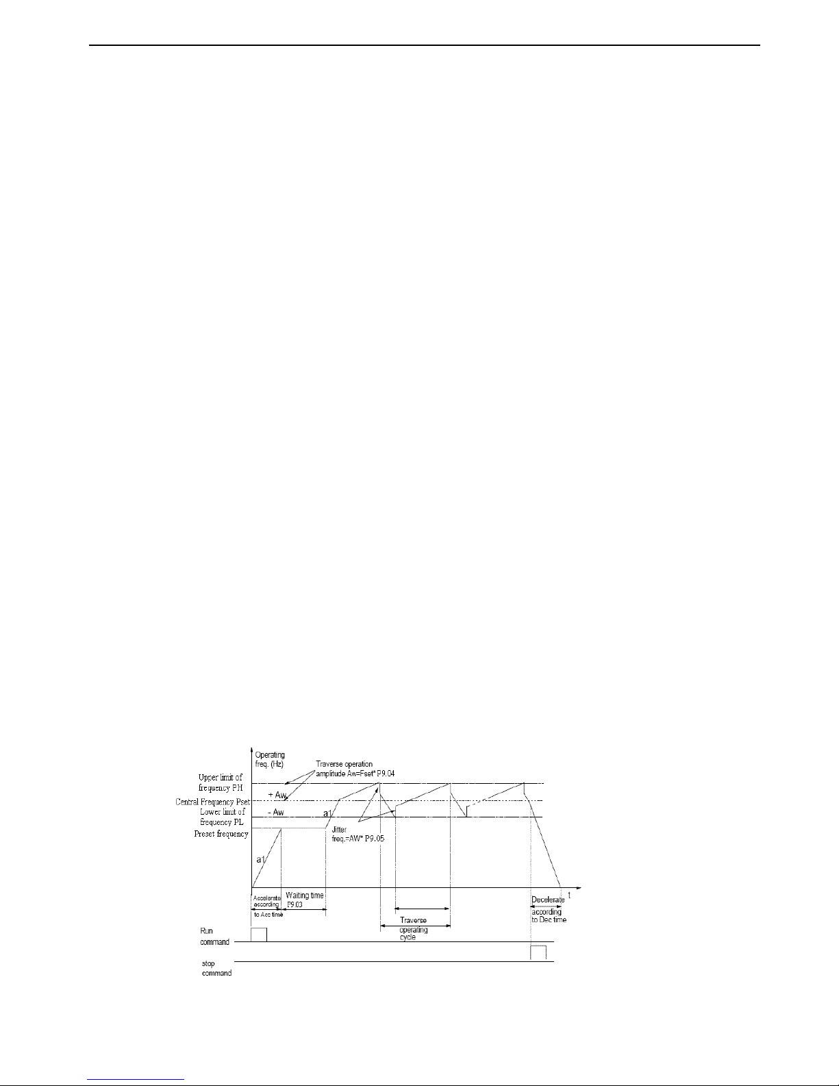
V5 series inverter
85
0
0
0
0 : Run
Run
Run
Run forward
forward
forward
forward
1
1
1
1 : Run
Run
Run
Run reverse
reverse
reverse
reverse
2
2
2
2 : Decided
Decided
Decided
Decided by
by
by
by operating
operating
operating
operating instructions
instructions
instructions
instructions
Hundred
Hundred
Hundred
Hundred
’
’
’
’
s
s
s
s place
place
place
place of
of
of
of LED
LED
LED
LED : Acc/D ectime selection
0
0
0
0 : Acc/Dec
Acc/Dec
Acc/Dec
Acc/Dec time
time
time
time 1
1
1
1
1
1
1
1 : Acc/Dec
Acc/Dec
Acc/Dec
Acc/Dec time
time
time
time 2
2
2
2
2
2
2
2 : Acc/Dec
Acc/Dec
Acc/Dec
Acc/Dec time
time
time
time 3
3
3
3
3
3
3
3 : Acc/Dec
Acc/Dec
Acc/Dec
Acc/Dec time
time
time
time 4
4
4
4
4
4
4
4 : Acc/Dec
Acc/Dec
Acc/Dec
Acc/Dec time
time
time
time 5
5
5
5
5
5
5
5 : Acc/Dec
Acc/Dec
Acc/Dec
Acc/Dec time
time
time
time 6
6
6
6
6
6
6
6 : Acc/Dec
Acc/Dec
Acc/Dec
Acc/Dec time
time
time
time 7
7
7
7
4-2-10
4-2-10
4-2-10
4-2-10 .
.
.
. Traverse
Traverse
Traverse
Traverse and
and
and
and measure
measure
measure
measure function
function
function
function parameters
parameters
parameters
parameters ( Group
Group
Group
Group P9
P9
P9
P9 )
Traverse operation is widely used in textile and chemical fiber industry . The typical application is shown in Fig. 5-37.
Traverse operation process: First, the drive accelerates to the preset frequency of traverse operation (F6.02) within the Acc
time and then waits for certain time (F6.03). The drive transits to the central frequency within Acc/Dec time, and at last the
drive traverse according to the preset traverse amplitude (F6.04), jitter frequency (F6.05), traverse cycle (F6.06) and rising
time of traverse operation (F6.07) until it receives a stopping command and stops within Dec time.
The central frequency is actually the preset frequency of simple operation (except PLC, traverse operation, jog ), multi-step
speed operation or PLC operations;
Traverse operating function is disabled automatically in Jog operation or close-loop operation process.
If PLC operation and traverse operation start at the same time, the traverse operation is disabled when the drive transits
from one PLC operating stage to another stage. The drive will accelerate to the preset frequency of PLC operation and then
start tra verse operation. The drive will decelerate to stop within the Dec time set in PLC operating stage.
Fig.
Fig.
Fig.
Fig. 4
4
4
4 - 45
45
45
45
T
T
T
T
raverse
raverse
raverse
raverse operation
operation
operation
operation
Page 92
V5 series inverter
86
0
0
0
0 : Disabled
Disabled
Disabled
Disabled
1
1
1
1 : Enabled
Enabled
Enabled
Enabled
Unit
Unit
Unit
Unit
’
’
’
’
s
s
s
s place
place
place
place of
of
of
of LED
LED
LED
LED : start mode
0
0
0
0 : Auto
Auto
Auto
Auto
mode
mode
mode
mode
.
.
.
. The inverter will running at preset frequency (P9.02) for certain time (P9.03), and then enter the traverse
operation.
1
1
1
1 : Manual
Manual
Manual
Manual
mode
mode
mode
mode
.
.
.
.
If the multi-function terminal (Xi is set to No. 25 function) is enabled, the inverter will enter traverse
mode. If the terminal is disabled, the drive will end traverse operation and operate at the pre-traverse frequency (P9.02).
Ten
Ten
Ten
Ten
’
’
’
’
s
s
s
s place
place
place
place of
of
of
of LED
LED
LED
LED : Traverse operating amplitude
0
0
0
0:Variable
Variable
Variable
Variable amplitude
amplitude
amplitude
amplitude
.
.
.
.
Traverse operating amplitude
AW
changes with the central frequency and the change rate is define
d
by
P9.04.
1
1
1
1 : Fixed
Fixed
Fixed
Fixed amplitude
amplitude
amplitude
amplitude
.
.
.
.
Traverse operating amplitude
AW
is decided
by
max frequency and P9. 04.
P9.02 is used to set running frequency before inverter enter traverse state.
If you select auto start mode, P9.03 is used to set the holding time with pre-traverse frequency before the inverter enter
traverse stat e; if you select manual start mode , P9.03 is disabled. Refer to Fig. 4 - 45 for introduction.
Variable amplitude :
Aw
= Central frequency × P9.04
Fixed amplitude :
Aw
= Max operting frequency P0.06 × P9.04
Prom p t : The traverse frequency will be limit
by
upper/lower limit of frequency, and the traverse operation will not work
abnormally with unsuitable set up.
As shown in Fig4-45, there is no jitter frequency if P9.05 is set to 0.
It defines the time of a complete traverse operation cycle including rising and falling processes.
Running time of traverse rising stage = P9.06 × P9.07( s ),Time of falling stage = P9.06
×
( 1 - P9.07
)
( s )。Refer Fig. 4 - 45
for introduction
Note
Note
Note
Note :
You
can select S-curve Acc/D
ec
mode along with traverse so as to make the traverse operating more smooth ly.
This group of parameters are used for fixed length control.
The drive inputs counting pulses via terminals (X 6, defined as function 35 ), and calculate length according to the number of
pulses per revolution ( P 9.1 3 ) and perimeter of shaft ( P 9.1 2 ).
Calculated length = Number of pulses ÷ number of pulses per revolution × perimeter of shaft
P9.00
P9.00
P9.00
P9.00
Traverse
Traverse
Traverse
Traverse operation
operation
operation
operation selection
selection
selection
selection
Range
Range
Range
Range : 0
0
0
0 ,
,
,
, 1
1
1
1
0
0
0
0
P9.01
P9.01
P9.01
P9.01
Traverse
Traverse
Traverse
Traverse operation
operation
operation
operation control
control
control
control mode
mode
mode
mode
Range
Range
Range
Range : 00
00
00
00 ~
11
11
11
11
0
0
0
0
P9.02
P9.02
P9.02
P9.02
Pre-traverse
Pre-traverse
Pre-traverse
Pre-traverse frequency
frequency
frequency
frequency
Range
Range
Range
Range : 0.00
0.00
0.00
0.00 - 650.00Hz
650.00Hz
650.00Hz
650.00Hz
0.00Hz
0.00Hz
0.00Hz
0.00Hz
P9.03
P9.03
P9.03
P9.03
Waiting
Waiting
Waiting
Waiting time
time
time
time before
before
before
before pre-traverse
pre-traverse
pre-traverse
pre-traverse frequency
frequency
frequency
frequency
Range
Range
Range
Range : 0.0
0.0
0.0
0.0 - 6000.0s
6000.0s
6000.0s
6000.0s
0.0s
0.0s
0.0s
0.0s
P9.04
P9.04
P9.04
P9.04
Traverse operating amplitude
Range
Range
Range
Range : 0.0
0.0
0.0
0.0 ~ 50.0
50.0
50.0
50.0 %
0.0
0.0
0.0
0.0 %
P9.05
P9.05
P9.05
P9.05
Jitter
Jitter
Jitter
Jitter frequency
frequency
frequency
frequency
Range
Range
Range
Range : 0.0
0.0
0.0
0.0 ~ 50.0
50.0
50.0
50.0 %
0.0
0.0
0.0
0.0 %
P9.06
P9.06
P9.06
P9.06
Traverse
Traverse
Traverse
Traverse operating
operating
operating
operating cycle
cycle
cycle
cycle
Range
Range
Range
Range : 0.1
0.1
0.1
0.1 ~ 999.9s
999.9s
999.9s
999.9s
10.0s
10.0s
10.0s
10.0s
P9.07
P9.07
P9.07
P9.07
Rising time of trangle wave
Range
Range
Range
Range : 0.0
0.0
0.0
0.0 ~ 98.0
98.0
98.0
98.0 %
50.0
50.0
50.0
50.0 %
P9.08
P9.08
P9.08
P9.08
Reference
Reference
Reference
Reference length
length
length
length
Range
Range
Range
Range : 0.000
0.000
0.000
0.000 ~ 65.535km
65.535km
65.535km
65.535km
0.000(km)
0.000(km)
0.000(km)
0.000(km)
P9.09
P9.09
P9.09
P9.09
Actual
Actual
Actual
Actual length
length
length
length
Range
Range
Range
Range : 0.000
0.000
0.000
0.000 ~ 65.535km
65.535km
65.535km
65.535km
0.000(km)
0.000(km)
0.000(km)
0.000(km)
P9.10
P9.10
P9.10
P9.10
Times
Times
Times
Times of
of
of
of length
length
length
length
Range
Range
Range
Range : 0.001
0.001
0.001
0.001 ~ 30.000
30.000
30.000
30.000
1.000
1.000
1.000
1.000
P9.11
P9.11
P9.11
P9.11
correction
correction
correction
correction coefficient
coefficient
coefficient
coefficient of
of
of
of
length
length
length
length
Range
Range
Range
Range : 0.001
0.001
0.001
0.001 ~ 1.000
1.000
1.000
1.000
1.000
1.000
1.000
1.000
P9.12
P9.12
P9.12
P9.12
Perimeter
Perimeter
Perimeter
Perimeter of
of
of
of shaft
shaft
shaft
shaft
Range
Range
Range
Range : 0.01
0.01
0.01
0.01 ~ 100.00(cm)
100.00(cm)
100.00(cm)
100.00(cm)
10.00(cm)
10.00(cm)
10.00(cm)
10.00(cm)
P9.13
P9.13
P9.13
P9.13
Number
Number
Number
Number of
of
of
of pulses
pulses
pulses
pulses per
per
per
per revolution
revolution
revolution
revolution
Range
Range
Range
Range : 1
1
1
1 ~ 9999
9999
9999
9999
1
1
1
1
Page 93
V5 series inverter
87
The calculated length can be corrected through times of length ( P9.10 ) and correction coefficient of length (P9.11)
,
and the
corrected length is the actual length.
Actual length = calculated length × correction coefficient of length ÷ correcting coefficient of length
When actual length( P 9. 09 ) ≥ preset length( P 9. 08 ), the inverter will send out a STOP command to stop . When the inverter
restarts, it needs to clear the actual length ( P 9. 09 ) or modify actual length ( P9.09 ) < Reference length ( P9.08 ),otherwise the
inverter will not start.
Note: (1) The actual length (terminal Xi is defined as function 36 ) can be cleared by multi-function input terminal. The
actual length can be calculated only after this terminal is disconnected.
(2) Actual length ( P 9. 09 ) will be saved after power off automatically.
(3) Function of stopping at fixed length is disabled if P9.08 I set as 0, but the calculated length is still effective.
4-2-11
4-2-11
4-2-11
4-2-11
.
.
.
.
Vector
Vector
Vector
Vector control
control
control
control parameters
parameters
parameters
parameters ( Group
Group
Group
Group
PA
PA
PA
PA
)
0
0
0
0 : No
No
No
No turning
turning
turning
turning
1
1
1
1 : Static
Static
Static
Static turning
turning
turning
turning
PA.01~PA.10 are set as motor parameters which ha ve default setting dependent on inverter’s modle
by
the factory , you can
reset these parameters according to the motor parameters of yours. P A.01~P A.10 are used for vector control,which should
be input correctly so as to realize the expecting effect.
In vector
control,
this
parameterisused
to
control torque currenttoavoid
over
current,
0~15 correspond to 50%~200% .
PA.00
PA.00
PA.00
PA.00
Motor
Motor
Motor
Motor auto-turning
auto-turning
auto-turning
auto-turning
Range
Range
Range
Range : 0
0
0
0 ,
,
,
, 1
1
1
1
0
0
0
0
PA.01
PA.01
PA.01
PA.01
Rated
Rated
Rated
Rated voltage
voltage
voltage
voltage of
of
of
of motor
motor
motor
motor
Range
Range
Range
Range : 0
0
0
0 ~ 400V
400V
400V
400V
Dependent
Dependent
Dependent
Dependent on
on
on
on
inverter
inverter
inverter
inverter
’
’
’
’
s
s
s
s model
model
model
model
PA.02
PA.02
PA.02
PA.02
Rated
Rated
Rated
Rated current
current
current
current of
of
of
of motor
motor
motor
motor
Range
Range
Range
Range : 0.01
0.01
0.01
0.01 ~ 500.00A
500.00A
500.00A
500.00A
Dependen
Dependen
Dependen
Dependen t
t
t
t on
on
on
on
inverter
inverter
inverter
inverter
’
’
’
’
s
s
s
s model
model
model
model
PA.03
PA.03
PA.03
PA.03
Rated
Rated
Rated
Rated frequency
frequency
frequency
frequency of
of
of
of motor
motor
motor
motor
Range
Range
Range
Range : 1
1
1
1 ~ 99Hz
99Hz
99Hz
99Hz
Dependen
Dependen
Dependen
Dependen t
t
t
t on
on
on
on
inverter
inverter
inverter
inverter
’
’
’
’
s
s
s
s model
model
model
model
PA.04
PA.04
PA.04
PA.04
Rated
Rated
Rated
Rated speed
speed
speed
speed of
of
of
of motor
motor
motor
motor
Range
Range
Range
Range : 1
1
1
1 ~ 9999
9999
9999
9999 r/min
r/min
r/min
r/min
Dependen
Dependen
Dependen
Dependen t
t
t
t on
on
on
on
inverter
inverter
inverter
inverter
’
’
’
’
s
s
s
s model
model
model
model
PA.05
PA.05
PA.05
PA.05
Polarity
Polarity
Polarity
Polarity of
of
of
of motor
motor
motor
motor
Range
Range
Range
Range : 2
2
2
2 ~ 48
48
48
48
Dependen
Dependen
Dependen
Dependen t
t
t
t on
on
on
on
inverter
inverter
inverter
inverter
’
’
’
’
s
s
s
s model
model
model
model
PA.06
PA.06
PA.06
PA.06
Stator
Stator
Stator
Stator inductance
inductance
inductance
inductance of
of
of
of motor
motor
motor
motor
Range
Range
Range
Range : 0.1
0.1
0.1
0.1 ~ 5000.0mH
5000.0mH
5000.0mH
5000.0mH
Dependen
Dependen
Dependen
Dependen t
t
t
t on
on
on
on
inverter
inverter
inverter
inverter
’
’
’
’
s
s
s
s model
model
model
model
PA.07
PA.07
PA.07
PA.07
Rotor
Rotor
Rotor
Rotor inductance
inductance
inductance
inductance of
of
of
of m
m
m
m otor
otor
otor
otor
Range
Range
Range
Range : 0.1
0.1
0.1
0.1 ~ 5000.0mH
5000.0mH
5000.0mH
5000.0mH
Dependen
Dependen
Dependen
Dependen t
t
t
t on
on
on
on
inverter
inverter
inverter
inverter
’
’
’
’
s
s
s
s model
model
model
model
PA.08
PA.08
PA.08
PA.08
Exciting
Exciting
Exciting
Exciting inductance
inductance
inductance
inductance of
of
of
of motor
motor
motor
motor
Range
Range
Range
Range : 0.1
0.1
0.1
0.1 ~ 5000.0mH
5000.0mH
5000.0mH
5000.0mH
Dependen
Dependen
Dependen
Dependen t
t
t
t on
on
on
on
inverter
inverter
inverter
inverter
’
’
’
’
s
s
s
s model
model
model
model
PA.09
PA.09
PA.09
PA.09
Stator
Stator
Stator
Stator re
re
re
re sis
sis
sis
sis t
t
t
t ance
ance
ance
ance of
of
of
of motor
motor
motor
motor
Range
Range
Range
Range : 0.001
0.001
0.001
0.001 ~ 50.000
50.000
50.000
50.000 Ω
Dependen
Dependen
Dependen
Dependen t
t
t
t on
on
on
on
inverter
inverter
inverter
inverter
’
’
’
’
s
s
s
s model
model
model
model
PA.10
PA.10
PA.10
PA.10
Rotor
Rotor
Rotor
Rotor resistance
resistance
resistance
resistance of
of
of
of motor
motor
motor
motor
Range
Range
Range
Range : 0.001
0.001
0.001
0.001 ~ 50.000
50.000
50.000
50.000 Ω
Dependen
Dependen
Dependen
Dependen t
t
t
t on
on
on
on
inverter
inverter
inverter
inverter
’
’
’
’
s
s
s
s model
model
model
model
PA.11
PA.11
PA.11
PA.11
Over
Over
Over
Over current
current
current
current protection
protection
protection
protection coefficient
coefficient
coefficient
coefficient of
of
of
of
torque
torque
torque
torque
Range
Range
Range
Range : 0
0
0
0 ~ 15
15
15
15
15
15
15
15
PA.12
PA.12
PA.12
PA.12
Percentage
Percentage
Percentage
Percentage adjustment
adjustment
adjustment
adjustment coefficient
coefficient
coefficient
coefficient of
of
of
of speed
speed
speed
speed dev
dev
dev
dev
Range
Range
Range
Range : 50
50
50
50 ~ 120
120
120
120
85
85
85
85
Page 94
V5 series inverter
88
In vector
control,
PA.12~PA.13
are
used for
control motor speed.Adjust
the
two parameters
can realize better
effect
for
motor
speed
control .
In vector
control,
this
parameterisused for
boosting motor’s
output
torque.
You
can
increase
this
parametertoboost
motor’s
output torque
in
the place
with too
heavy
load.
4-2-12
4-2-12
4-2-12
4-2-12
.
.
.
.
Specail
Specail
Specail
Specail a
a
a
a pplication
pplication
pplication
pplication function
function
function
function parameters
parameters
parameters
parameters ( Group
Group
Group
Group PB
PB
PB
PB )
0
0
0
0 : P3.06
P3.06
P3.06
P3.06
1
1
1
1 :
Panel
Panel
Panel
Panel
poten
poten
poten
poten tiometer
tiometer
tiometer
tiometer
2
2
2
2 : P0.02
P0.02
P0.02
P0.02
3
3
3
3 : VI
VI
VI
VI
4
4
4
4 : CI
CI
CI
CI
0
0
0
0 : Dead
Dead
Dead
Dead
time
time
time
time is
is
is
is
enabled
enabled
enabled
enabled
.
.
.
.
A ccording
to
the value setbyP0.05 with
the
min i mum
value
0.1S 。
1
1
1
1:D
D
D
D ead
ead
ead
ead time
time
time
time can
can
can
can
be
be
be
be
set
set
set
set
to
to
to
to
0
0
0
0(no
no
no
no
dead
dead
dead
dead time
time
time
time).
.
.
.
You
should set
P0.05=0.0s,P0.20 ≥ 0.5Hz。( P0.17 ≤ 0.5S,P0.18 ≤ 0.5S,P 0.20
≥
2.0Hz,
P2.01 ≥ 2.0Hz
) 。
This function
is usually
used
in
the
control process of continuous to-and-for
control.Ifswift
turn-
aroundisneeded,reduce
the Acc/Dec
time
and
increasethe lower
limit
of frequency/start
frequency.
( P0.17 ≤ 0.5S,P0.18 ≤ 0.5 S
,
P0.20 ≥
2.0Hz,
P2.01 ≥ 2.0Hz ) .
0:
0:
0:
0:
G
G
G
G
type
type
type
type
(normal),
(normal),
(normal),
(normal), used
used
used
used
in
in
in
in
normal
normal
normal
normal
situation
situation
situation
situation
1:
1:
1:
1:
P
P
P
P
type
type
type
type
(wind
(wind
(wind
(wind machine,water
machine,water
machine,water
machine,water pump),
pump),
pump),
pump), used
used
used
used
in
in
in
in
wind
wind
wind
wind machine,
machine,
machine,
machine,
water
water
water
water
pump
pump
pump
pump and
and
and
and
other
other
other
other small
small
small
small
load
load
load
load
situation.
situation.
situation.
situation.
Under
this
mode,
power
will
improve1time, if the
machine poweris2.2KW,
underPtype mode,
the
power
will
be
3.7KW.
Please note P0.22
should
be
set as
3.
0:
0:
0:
0:
before
before
before
before
power
power
power
power
on,
on,
on,
on,
if
if
if
if
the
the
the
the
point
point
point
point is
is
is
is
short,
short,
short,
short,
run
run
run
run
the
the
the
the
inverter
inverter
inverter
inverter immediately.
immediately.
immediately.
immediately.
1:
1:
1:
1:
before
before
before
before
power
power
power
power
on,
on,
on,
on,
if
if
if
if
the
the
the
the
point
point
point
point is
is
is
is
short,
short,
short,
short,
run
run
run
run
the
the
the
the
inverter
inverter
inverter
inverter
after
after
after
after cut
cut
cut
cut
off
off
off
off
the
the
the
the
point
point
point
point
and
and
and
and
connect
connect
connect
connect
it
it
it
it
again.
again.
again.
again.
4-2-13
4-2-13
4-2-13
4-2-13
.
.
.
.
Factory
Factory
Factory
Factory setting
setting
setting
setting ( Group
Group
Group
Group PF
PF
PF
PF )
iation
iation
iation
iation
PA.13
PA.13
PA.13
PA.13
Integral
Integral
Integral
Integral adjustment
adjustment
adjustment
adjustment coefficient
coefficient
coefficient
coefficient of
of
of
of speed
speed
speed
speed
deviation
deviation
deviation
deviation
Range
Range
Range
Range : 100
100
100
100 ~ 500
500
500
500
360
360
360
360
PA.14
PA.14
PA.14
PA.14
Vector
Vector
Vector
Vector torque
torque
torque
torque boost
boost
boost
boost
Range
Range
Range
Range : 100
100
100
100 ~ 150
150
150
150
80
80
80
80
PB.00
PB.00
PB.00
PB.00
Jog
Jog
Jog
Jog frequency
frequency
frequency
frequency source
source
source
source
Ran
Ran
Ran
Ran ge
ge
ge
ge : 0
0
0
0 ~ 4
4
4
4
0
0
0
0
PB.01
PB.01
PB.01
PB.01
selection
selection
selection
selection of
of
of
of forward/
forward/
forward/
forward/ reverse
reverse
reverse
reverse dead
dead
dead
dead time
time
time
time
Range
Range
Range
Range : 0
0
0
0 ,
,
,
, 1
1
1
1
0
0
0
0
PB.02
PB.02
PB.02
PB.02
I nverter type select
range
range
range
range : 0
0
0
0 、 1
0
0
0
0
PB.03
PB.03
PB.03
PB.03
R
R
R
R un
un
un
un mode
mode
mode
mode
range
range
range
range : 0
0
0
0 、 1
1
1
1
1
PF.00
PF.00
PF.00
PF.00
Default
Default
Default
Default password
password
password
password
-
-
Page 95
V5 series inverter
89
This parameter can be protect against unauthorized personnel to view or modify function parameters.
If user’s password don ’ t need, you can set 0000 as its value.
If usre’s password is needed, input four figures as password , then press to confirm, the password w i ll be valid
immediately.
Modification : Press key to va lidate password,with correct pass word you can enter parameter editing status. After
s elect ing PF.01 (PF.01=0000)
,
input new password and press to confirm , then the password will be valid
immediately. The password for super user is “ 2 644 ”
.
Software version is setbyfactory and it can not be modified
by
user.
PF.01
PF.01
PF.01
PF.01
User
User
User
User
’
’
’
’
s
s
s
s password
password
password
password
Range
Range
Range
Range : 0000
0000
0000
0000 ~ 9999
9999
9999
9999
0000
0000
0000
0000
PF.02
PF.02
PF.02
PF.02
Software
Software
Software
Software version
version
version
version
-
-
MENU
ESC
Page 96
V5 series inverter
90
5
5
5
5 Fault
Fault
Fault
Fault Diagnosis
Diagnosis
Diagnosis
Diagnosis and
and
and
and Countermeasures
Countermeasures
Countermeasures
Countermeasures
5-1.
5-1.
5-1.
5-1. Fault
Fault
Fault
Fault diagnosis
diagnosis
diagnosis
diagnosis and
and
and
and countermeasurs
countermeasurs
countermeasurs
countermeasurs
When fault occurs, the function code and its contents will be shown in LED display,the protection function starts, the inverter
stops outputting and the fault
relay
contact point is activated .Before seeking services, the subscriber may conduct the self-
check according to the prompt given in this section, analyze the fault causes, and find out the solutions.If the fault belo ngs to
the causes described in the broken line box, please seek the service
by
contacting the inverter agent or directly contacting our
corporationl.
Table
Table
Table
Table
5-1
5-1
5-1
5-1 Fault
Fault
Fault
Fault content
content
content
content and
and
and
and countermeasures
countermeasures
countermeasures
countermeasures
Fault
Fault
Fault
Fault Code
Code
Code
Code
Fault
Fault
Fault
Fault Type
Type
Type
Type
Possible
Possible
Possible
Possible r
r
r
r eason
eason
eason
eason of
of
of
of fault
fault
fault
fault
countermeasure
countermeasure
countermeasure
countermeasure
E-01
Over-current
during
acceleration
Too heavy the load and too short the Acc time
Prolong the Acc time
V/F curve is not suitable
Adjust V/F curve
The rota ting motor restarts after stop
Set as “ start on fly ” function
Too large the value of torque boost
Adjust the value of manual torque boost or chan geitas
auto torque
Inverter power is too low
Select a high power inverter
E-02
Over-current during
decele ration
Too short Dec time
Prolong the Dec time
The load generates energy or the load inertial is
too big
Connect suitable braking kit
Inverter power is too low
Select a high power inverter
E-03
Over-current during
constant speed
Sudden change of load
Check and reduce the change of load
Too short Acc/Dec time
Prolong Acc/Dec time
Abnormal load
Check the load
A C supply voltage is low
Check AC supply voltage
Inverter power is too low
Select a high power inverter
E-04
Over-voltage durning
acceleration
Abnormal input voltage
Check input voltage
Too short Acc time
Prolong Acc time
The rotating motor restarts after stop
Set as “ start on fly ” function
E-05
Over-voltage durning
deceleration
Too short Dec time
Prolong Dec time
The load generates energy or the load inertial is
too big
Connect suitable braking kit
E-06
Over-voltage
Durning constant
speed operation
Abnormal input voltage
Check input voltage
Too short Acc /Dec time
Prolong Acc/Dec time
Abnormal change of input voltage
Install input reactor
Too big the load inertial
Connect suitable braking kit
E-07
Inverter’s control
power supply over
voltage
Abnormal input voltage
Check input power or ask for service
E-08
Inverter overheat
Vent
obstructed
Clean the vent
Over temperature
Improve condition and decrease carrier frequency
Fan does not work
Change the fan
IGBT module is abnormal
Ask for help
E-09
Inverter overload
Too short Acc time
Prolong Acc time
Page 97
V5 series inverter
91
DC injection braking current is too big
R educe DC injection braking current and prolong braking
time
V/F curve is not suitable
Adjust V/F curve and torque boost value
The rotating motor restarts after stop
Set “ start o f fly ” function
Low AC supply voltage
Check AC supply voltage
Too heavy load
Select a high power inverter
E-10
Motor overload
V/F curve is not suitable
Adjust V/F curve and torque boostvalue
Low AC supply voltage
Check AC supply voltage
Common motor has operated with heavy load
at low speed for a long time
Select motor with frequency conversion if it requires to
operate for a long time
Unsuitable motor’s overload protection
coefficient
Set motor’s overload protection coefficient correctly
The motor is blocked or the load is too big
Check load
E-11
Low voltage durning
operating
Too low AC supply voltage
Check AC supply voltage
E-12
IGBT protection
Instant over current of inverter
Refer to countermeasure of over current
Short-circuit among 3-phase output or
line-to-ground short circuit
R ewiring
Vent
is obstructed or fan is damaged
Clean the vent or change the fan
Over-temperature
Reduce environment temperature
Wires or connectors of control board are loose
Check and rewiring
Current waveform distorted due to output phase
loss
Check wiring
Auxiliary power is damaged and inverter
voltage is low
Seek factory or agent for service
Abnormal control board
Seek factory or agent for service
E-13
P eripheral equipment
fault
Emergency stop for peripheral equipment
terminal close
B reak external fault terminal after dealing with the
external fault
E-14
Current
detection circuit
has fault
Wires or connectors of control board are loose
Check and rewiring
Auxiliary powe is damaged
Seek factory or agent for service
Hall sensor is damaged
Seek factory or agent for service
Amplifying circuit is abnormal
Seek factory or agent for service
E-15
RS485
Communication
error
Baud rate is not suitable
Set suitable baud rate
Serial port communication error
Press key to reset , or seek service
Improper setting of alarm parameter
Modify the setting of P3.09 ~ P3.12
Host PC does not work
Check host PC, check the wiring
E-16
System disturbance
Severe disturbance
Press key to reset or install power filter at the input
side of the inverter
W/R error of DSP in main control board
Press keys to reset or seek service
Page 98
V5 series inverter
92
5-2.
5-2.
5-2.
5-2. F
F
F
F ault
ault
ault
ault records
records
records
records
This series inverter reco rds the codes of latest6fault and operating parameters of last1fault which can be help for finding
the possible reason of faults. All of these fault informations are saved in group P6.Please refer operation methord of
keyboard to enter group P6.
5-3.
5-3.
5-3.
5-3. Fault
Fault
Fault
Fault reset
reset
reset
reset
Once the fault occurs, select one of the following operations to restart the inverter:
(1) When fault code displayed in the operation panel, press key after you confirm the inverter can be reset.
(2) After setting one terminal among X1 ~ X8 as external RESET input (P4.00 ~ P4.07=17)
,
connect it with COM terminal
and then disconnect them.
(3) Cut off the power supply
(1) Please make sure you know the reason of the fault and get rid of it before reset ting, otherwise the inverter may be
damaged permanently.
(2) If the inverter can not be reset or fault reoccurred after resetting
,
please check the reason as the inverter may be
damaged
by
resetting continuously.
(3) Delay 5 minutes to reset when overload and overheat protection are enabled.
E-17
E2PROM
W/R error
W/R error of control parameter
Press key to reset or seek service
E-18
DC brake overcurrent
S et wrong current of DC brake
D ecrease the brake current %
E-24
M ain circuit lack
voltage,the
electromagnetic
contacter action error
L ack of phase when input current, momentary
power off, power supply point loose, power
supply voltage fluctuate s serious and make the
main circuit contacter open
C heck the reason and reset
C heck the power supply
A sk the factory
E-30/31
L ack of phase when
inverter running or
stop
I nput power supply lack of phase, momentary
power off, power supply point loose, power
supply voltage fluctuates serious and make the
voltage between phases unbalance
C heck the reason then reset
EEEE
P anel communication
error
O perate panel and CPU board connection is not
good, the control circuit of inverter is not good
U ninstall the operate panel and install again, ask
the factory for help
Note
Note
Note
Note :
Page 99
V5 series inverter
93
6
6
6
6 Maint
Maint
Maint
Maint e
e
e
e n
n
n
n an
an
an
an ce
ce
ce
ce
6-1.
6-1.
6-1.
6-1. Maintenance
Maintenance
Maintenance
Maintenance
Environment effections such as ambient temperature, humidity, fog , internal component aging and other factors will give rise to the occurrence
of potential faults. Therefore, it is necessary to conduct daily check and routine maintenance to the inverters.
6-1-1
6-1-1
6-1-1
6-1-1
.
.
.
.
Routine
Routine
Routine
Routine maintenance
maintenance
maintenance
maintenance
Please confirm the following items when start the inverter.
( 1 ) If there is abnormal noise and vib ration with th motor.
( 2 ) I f the inverter and motor heat unusually.
( 3 ) If the environment temperature is too high.
( 4 ) If the value of load a m p ero meter is as usual.
( 5 ) If the fan of inverter can operate normally.
6-2.
6-2.
6-2.
6-2. Periodical
Periodical
Periodical
Periodical care
care
care
care and
and
and
and ma
ma
ma
ma i
i
i
i nt
nt
nt
nt e
e
e
e n
n
n
n a
a
a
a nce
nce
nce
nce
6-2-1
6-2-1
6-2-1
6-2-1 .Periodical
.Periodical
.Periodical
.Periodical care
care
care
care
Before check and maintenance the inverter, please make sure that the inverter is power off, monitor has no display content
and the indication lamp of main circuit power is off .The checked contents are shown in Tabel 6-1.
Table
Table
Table
Table
6-1
6-1
6-1
6-1 periodical
periodical
periodical
periodical maintenance
maintenance
maintenance
maintenance
6-2-
6-2-
6-2-
6-2- 2.
2.
2.
2. Periodical
Periodical
Periodical
Periodical maintenance
maintenance
maintenance
maintenance
To
make the inverter work normally for long time, periodical care and maintenance for inverter’s internal electronic
component should be done . The electronic component’s lifetime depends largely on their application environment and
preservation. Normally, lifetime is:
Items
Contents
Countermeasures
Main circuit terminals , control
circuit terminals
If the screws are loose
Tight en the screws with screw drivers
Heatsink
If there is dust
Use d r y compressed air w ith 4 ~ 6 kgcm
2
pressure
PCB print circuit board
If there is dust
Use dry compressed air with 4 ~ 6 kgcm
2
pressure
Cooling fan
T here is abnormal noise, vibration, or if it has run for
more than 20 000 hours.
Change cooling fan
Power component
If there is dust
Use dry compressed air with 4 ~ 6 kgcm
2
pressure
Aluminium electrolytic capacitors
If it has changed color , particular smell or bubble
Change aluminium electrolytic capacitors
Page 100

V5 series inverter
94
Table
Table
Table
Table
6-2
6-2
6-2
6-2 Lifetime
Lifetime
Lifetime
Lifetime of
of
of
of inverter
inverter
inverter
inverter components
components
components
components
The usage condition s of the above components are shown below:
( 1 ) Environmental temperature : 30 ℃ as average.
( 2 ) Load coefficient : below 80% .
( 3 ) Running time : below 12 hour per day .
6-3.
6-3.
6-3.
6-3. Warranty
Warranty
Warranty
Warranty of
of
of
of the
the
the
the inverter
inverter
inverter
inverter
Xinje electronic Co. ,Ltd will offer warranty service in the case of the following situations:
( 1 ) The warranty clause is only confined to the inverter ;
( 2 )
We
will take the responsibility of 1 5 months defects liability period for any faults or damages under the normal
operation conditions. After1 5 months, maintenance will be charged;
( 3 ) Even within 1 5 months, maintenance would be charged under the following conditions:
Inverter is damaged due to incorrect operation, which are not in compliance with “ User Manual ” ;
Inverter is damaged due to fire, flood, abnormal voltage and so on;
Inverter is damaged due to wiring fault.
Inverter is damaged due to the improper use of drive functions;
(4) Service fee will be charged according to the actual costs. If there are any maintenance contracts, the contract prevail.
Component
Life
Cooling fan
2 ~ 3 year
Electrolytic capacitors
4 ~ 5 year
Print circuit boare
5 ~ 8 year
Fuse
10 year
 Loading...