


TP/TH/TG series HMI
manual【Hardware】
WUXI XINJE ELECTRIC CO., LTD.
Data No. : HC 01 20120105 2C6


I
CATALOG
1 TP SERIES HMI ................................................................................................................................................. 1
1-1 Features ............................................................................................................................ 1
1-1-1 Product features .................................................................................................... 1
1-1-2 Model naming rule ................................................................................................ 1
1-1-3 Product models...................................................................................................... 2
1-2 General specifications .................................................................................................... 2
1-3 Hardware .......................................................................................................................... 3
1-3-1 Hardware structure ............................................................................................... 3
1-3-2 Port introduction .................................................................................................... 3
1-4 Dimension and installation ............................................................................................. 7
1-4-1 Product dimensions .............................................................................................. 7
1-4-2 Installation and using environment ..................................................................... 8
2 TH SERIES HMI .............................................................................................................................................. 10
2-1 Features ........................................................................................................................... 10
2-1-1 Product features .................................................................................................. 10
2-1-2 Model naming rule .............................................................................................. 11
2-1-3 Model form ........................................................................................................... 11
2-2 General specifications.................................................................................................... 12
2-3 Hardware ......................................................................................................................... 14
2-3-1 Hardware structure ............................................................................................. 14
2-3-2 Port introduction .................................................................................................. 14
2-4 Dimensions and installation .......................................................................................... 20
2-4-1 Product dimensions ............................................................................................ 20
2-4-2 Installation and using environment ................................................................... 22
3 TG SERIES HMI .............................................................................................................................................. 24
3-1 Features ........................................................................................................................... 24
3-1-1 Product features .................................................................................................. 24
3-1-2 Module naming rule ............................................................................................ 25
3-1-3 Product models.................................................................................................... 25
3-2 General specifications.................................................................................................... 26
3-3 Hardware ......................................................................................................................... 27
3-3-1 Hardware structure ............................................................................................. 27
3-3-2 Ports introduction ................................................................................................ 28
3-4 Dimensions and installation .......................................................................................... 31
3-4-1 Product dimensions ............................................................................................ 31
3-4-2 Installation and using environment ................................................................... 34


1
1 TP series HMI
1-1 Features
Xinje TP series HMI have strong functions. It supports multi-language, any font and size of
characters. The basic functions include data display and monitoring, alarm, recipe. It can
communicate with most brands of PLC, two ports can communicate individually. The
programming software Touchwin has friendly interface and easy to operate. The software
can simulate online and offline (SCADA function).
1-1-1 Product features
Display
Monochrome or 256 colors LCD, support BMP, JPG pictures display
Support multi-language: Chinese, English, Japanese, Korean, German, French,
Arabic, etc. The fonts support any size, artistic effect, bold, italic, etc.
Large program capacity support more program screens and data.
Control
Dynamic data displaying and monitoring, bar map, real-time/historical trend map,
discrete/continuous histogram, switching control;
Real-time/historical alarm records;
Sample and save the data at certain time or conditions;
Nine levels password protection;
On/off line simulation, SCADA function
Communication
Two ports can communicate independently, enable to connect many devices at the
same time;
Support micro-printer
Support free format communication, user can make the communication protocol
freely.
1-1-2 Model naming rule
□□○○○—□
1 2 3
1:Series name TP
2:LCD size 460:4.7’’
760:7.0’’
3:LCD display L:Monochrome LCD
T:256 colors TFT LCD
2
1-1-3 Product models
TP series HMI can connect to PLC, inverter, meters and other devices. As the interface of
machine and user, it can monitor data, control the machine operation. It is fit for small and
medium control systems.
1-2 General specifications
HMI specifications
Item
TP460-L
TP760-T
Screen
Size
4.7″
7.0″
Type
Monochrome
256 colors
Resolution
240*128
480*234
Brightness
Adjust by potentiometer
/
Touch panel
Matrix digital touch panel
Using life
More than 50000 hours, temperature 25℃,running for 24 hours
Language
Chinese, English, Japanese, Korean, German, French,
Arabic…
Character
Any font and size
Memory
Capacity
2MB
4MB
Electric specifications
Item
TP460-L
TP760-T
Electric
Input voltage
DC24V (voltage range: DC22V-DC26V)
Consumption
current
200mA
280mA
Allowable
momentary power
failure
Below 10ms (Actual power failure<1s)
Withstand voltage
AC1000V,10mA,less than 1 minute (signal and ground)
Insulated
impedance
DC500V, above 10MΩ (signal and ground)
Environment
Operation
temperature
0-50℃
Reserve
temperature
-20-60℃
Environment
humidity
10%RH-90%RH (no condensation)
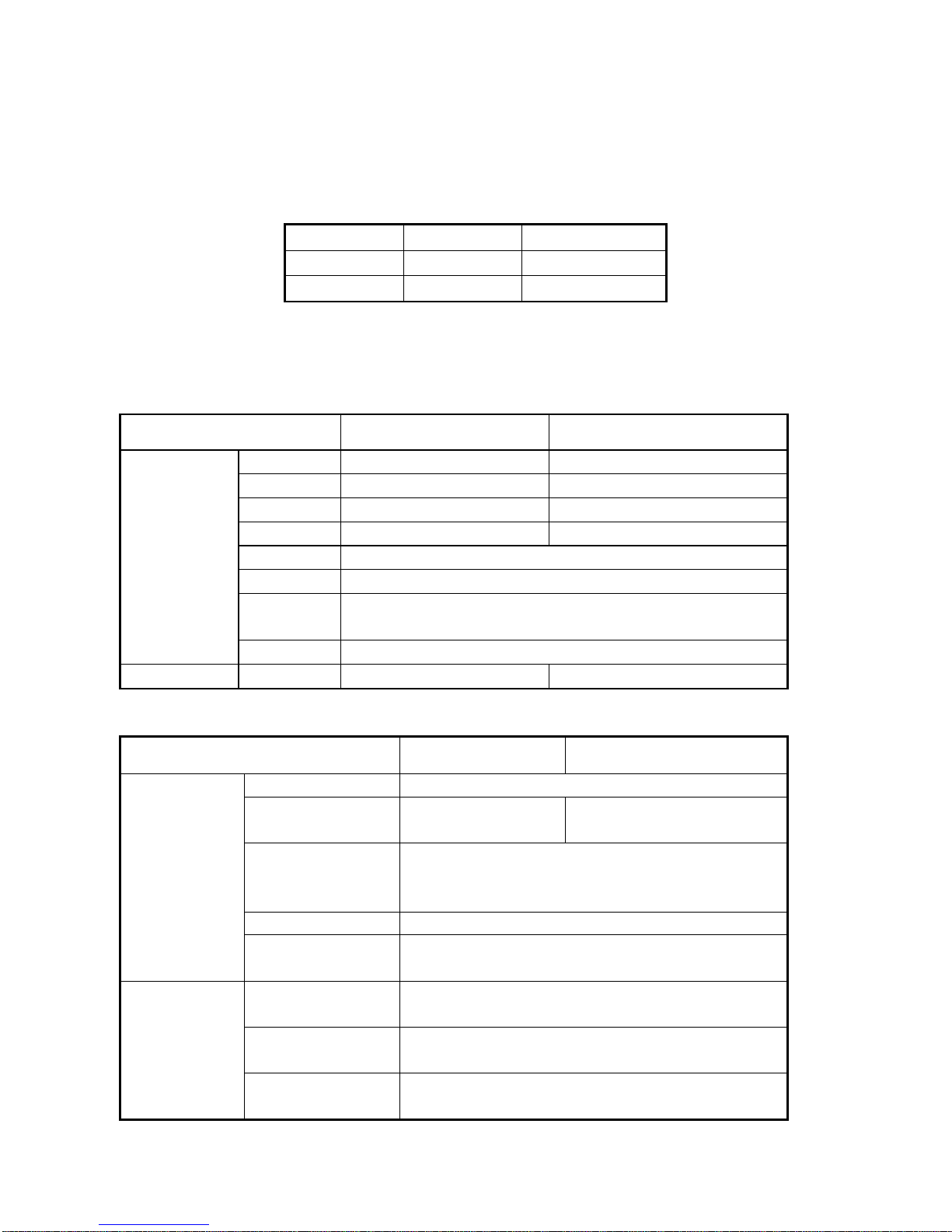
Model
LCD size
LCD type
TP460-L
4.7 inch
Monochrome LCD
TP760-T
7.0 inch
256 colors TFT

3
Withstand oscillation
10-25HZ(X,Y,Z each direction 30 minutes 2G)
Anti-jamming
Voltage noise:1500Vp-p,pulse 1us,1 minute
Surrounding air
No corrosive gas
Protection
construction
IP65
Construction
Cooling method
Natural air cooling
Exterior dimension
(mm)
173.2*121.4*45.1
200.0*148.0*45.0
Mounting dimension
(mm)
165.2*113.4
182.4*134.4
Ports
PLC port
Support RS232/RS485/RS422
Download port
Support RS232/RS485
1-3 Hardware
1-3-1 Hardware structure
The hardware structure of TP series touch screen includes front and back side. Take
TP460-L as an example to explain the structure.
1-3-2 Port introduction
Xinje TP series HMI have two communication ports: Download port and PLC port, below is
the feature and function of TP series, take the ports of TP460-L as an example:
Power supply
Download port
PLC port
Nameplate
4
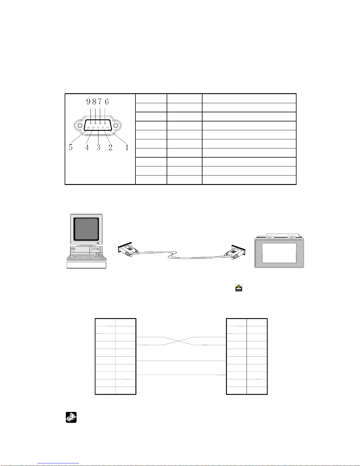
1. Download communication port
The main functions of the port:
Download: Connect with PC to download program;
Communication: Connect with PLC, printer, frequency converter etc, as a
communication port.
Pins of download port:
Pin
Name
Meaning
1
NC
Unused terminal
2
RXD
RS232 receive
3
TXD
RS232 send
4
A
RS485 communication “+” signal
5
GND
Signal ground
6
BUSY
Busy signal
7
B
RS485 communication “-” signal
8
NC
Unused terminal
9
NC
Unused terminal
(1) Download function
When you use download function of TP series, please use Xinje special download cable:
Before user download a program, please make sure your PC has installed multiport serial
card or USB-RS232 convertor, and connect cable correctly, click “ ” button in Touchwin
software, then you could download data successfully, below are the pin definitions:
PC serial Port (COM) Download Port (TP series)
Connection diagram (Normal download)
If the connection between PC and HMI is correct, but still can’t download, user
Pin 1 2 3 4
5
6 7 8
9
RXD
TXD
GND
RTS
NC
NC B BUSY
GND
A
TXD
RXD
NC
9
8 7 6
5
4 3 2 1 Name
Pin
Name
5
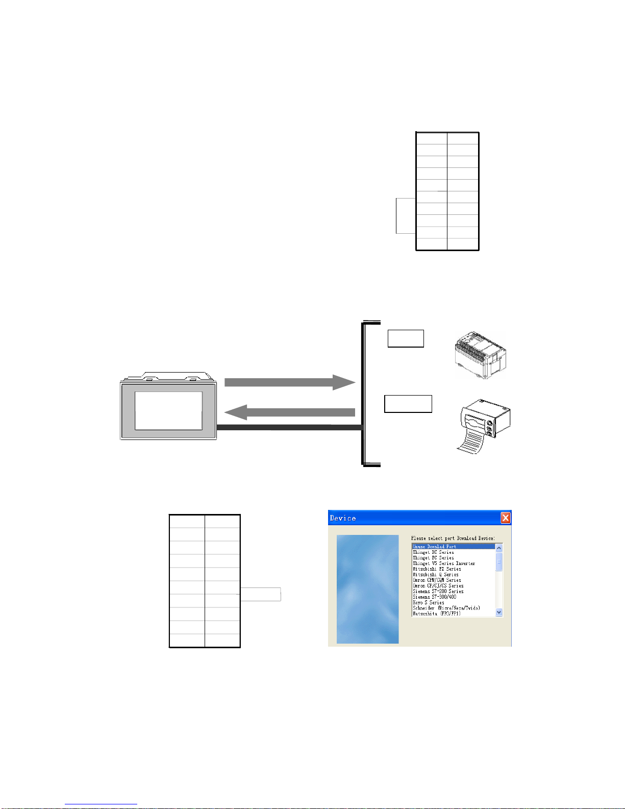
can try “Forced Download” function. The connection diagram of this function as
below shows:
Download Port (TP series)
pin5&8 shorted forced download mode
Steps:
a. Cut the power of TP, shorted the Pin 5 and 8;
b. Power on, move away the shorted line;
c. Start to download the program with special download cable.
(2) Communication function
The download port of TP series not only has the download function, but also has the
powerful communication function.
When use the communication function of download port, please shorted the pin 5 and pin
6, select the corresponding communication equipment in software settings.
Download port communication mode transformation Select communication device of download port
Receive data
Send data
Printer
PLC
TP Series HMI
Download communication port
Pin
Name 1 2 3 4 5 6 7 8 9 NC
RXD
TXD A GND
BUSY B NC
NC
NC
NC
B
BUSY
GND A TXD
RXD
NC
9
8
7
6 5 4
3 2 1
Name
PIN
6
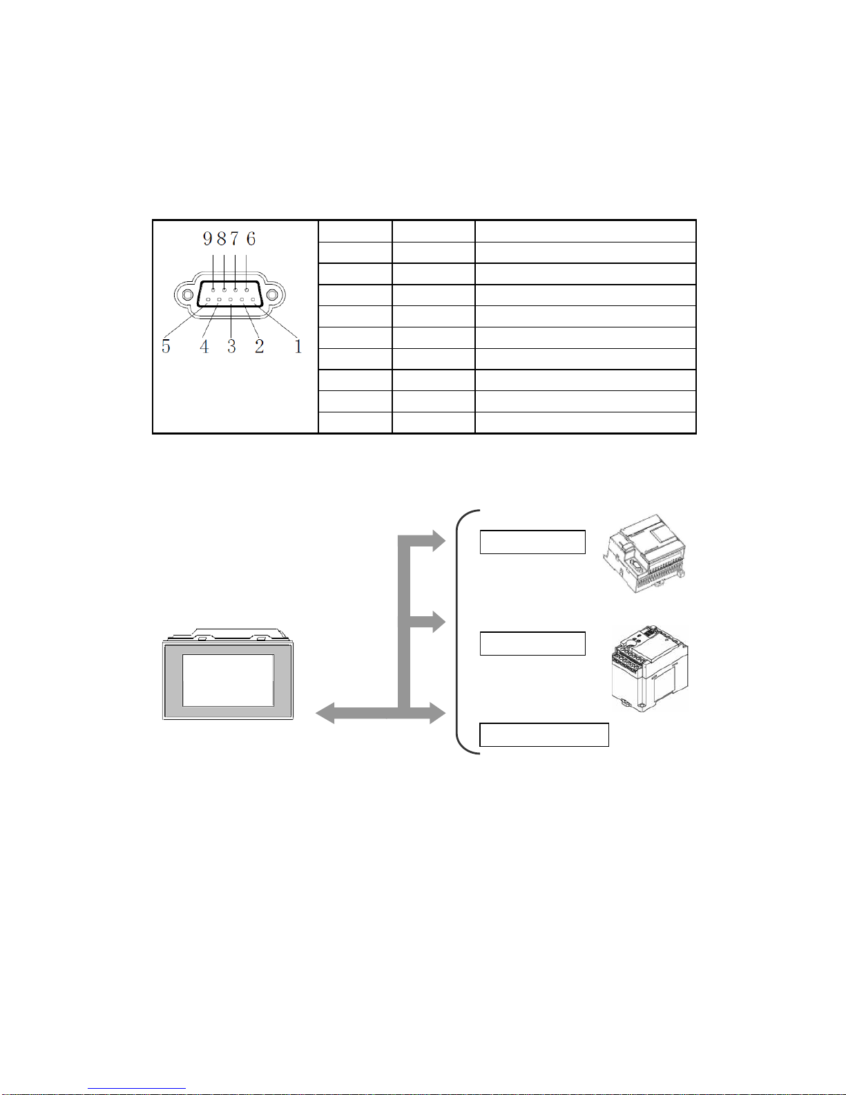
2. Communication interface of PLC
The PLC communication port of TP series has below function:
Connect and communication with industrial control equipments: PLC, inverter,
meter etc.
The pins definition of PLC communication port:
Pin
Definition
Description
1
TD+
RS422 send “+”
2
RXD
RS232 receive
3
TXD
RS232 send
4
A
RS485 “+”
5
GND
Signal ground
6
TD-
RS422 send “—”
7
B
RS485 “—”
8
RDD-
RS422 receive “—”
9
RDD+
RS422 receive “+”
(1) Communicate with PLC
TP series HMI can communicate with most of popular PLCs
Please select correct PLC port device and communication parameters:
Data transfer
TP Series
PLC com port
SIEMENS PLC
Panasonic PLC
Other PLCs

7
(2) Communicate with inverter
TP can communicate with various brands of frequency inverters. For the brands which are
not in the list, user can select Modbus protocol or user-defined protocol.
(3) Communicate with meters
About the communication between TP and meters, users can select user-defined protocol
or Modbus protocol.
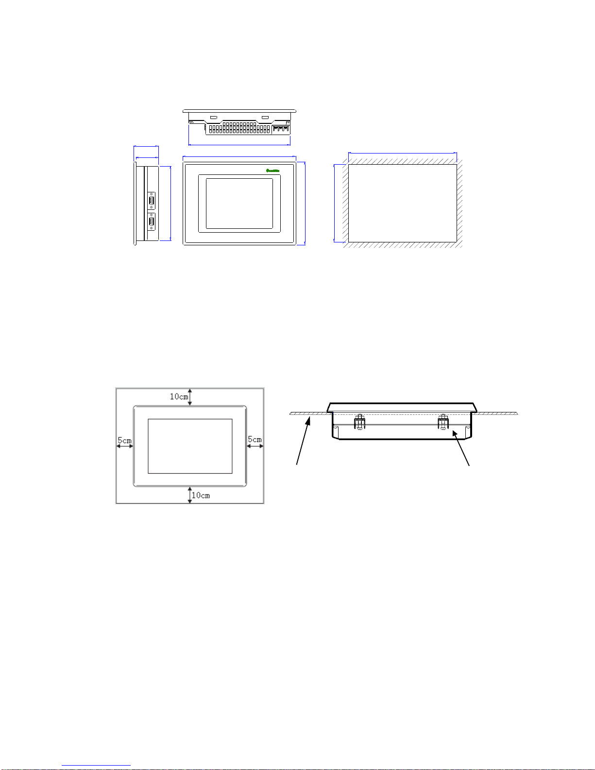
1-4 Dimension and installation
1-4-1 Product dimensions
TP460-L (Unit: mm)
0.0
+0.5
0.0
+0.5
40.6
165.0
113.0
163.2
45.1
111.4
121.4
173.2
PLC com port
TP series
Mitsubishi FR series inverter
Inovance MD series inverter
Bosch Rexroth FE series
inverter
8
TP760-T (Unit: mm)
180.4
200.0
148.0
134.4
182.4
0.0
+0.5
0.0
+0.5
132.4
44.4
40.0
1-4-2 Installation and using environment
Install requirements:
TP has four ferric mounting racks when out of factory, there are two square holes on the
top, bottom side of TP, use mounting rack to fix the TP with control cabinet.
In order to avoid TP temperature too high after long time working, please keep 10cm
space on the up/down and 5cm on the left/right side of the TP when installing.
Install steps:
1. Refer to the dimension in the former chapter to open a rectangle mounting hole in
the control cabinet
2. Add airproof circles in the airproof slot when installing
3. Insert the bottom of TP into the mounting hole of control cabinet
4. Insert the install rack into the fix hole of TP then tighten the screw
5. Connect TP and PLC with communication cable
Notice: The communication cable can be offered by the supplier or made by user
according to the connection diagram, input +24V DC power to start working.
Environment:
Please use TP series touch screen indoor.
Fixed bracket
Install panel

9
Do not use TP in below environment:
Inflammable gas, steam, dust, fast vary temperature, high humidity (it may cause moisture
inside TP).
Power supply requirements:
TP series touch screen use DC +24V power supply only. The permitted voltage range is
20V~26V. The connection is as below:
+24V
0 V
+DC-
+DC-
0 V
+24V
Terminal type Pin type
Besides, if connect high voltage or AC power supply with TP, the TP may be damaged and
cause electric shock to human body.
NOTE: if use the DC +24V output of PLC to drive the TP, make sure the PLC
has enough current to drive the TP.
 Loading...