

Xinje DS3-20P2-PQA, DS3E-20P2-PFA, DS3L-20P2-PFA, DS3-20P2-PTA, DS3-20P4-PQA User Manual
...
DS3/DS3E/DS3L series servo drive
User manual
Serial No. SC3 02 20171010 1.0
WUXI XINJE ELECTRIC CO., LTD.

All copyrights reserved by WUXI XINJE ELECTRIC CO., LTD.
Any copying, transferring or any other usage is pro hibited. Otherwise Xinje will have the right to
pursue legal responsibilities. All rights including patent and pemission of modules and designs are
reserved.
January, 2010
a
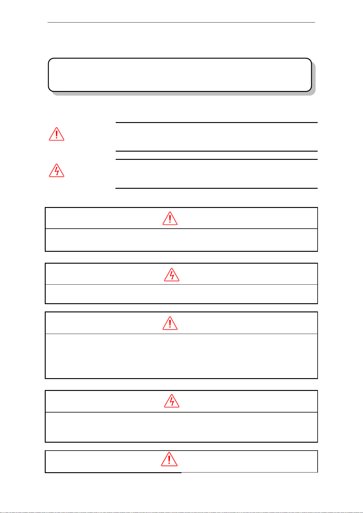
CAUTION
Indicates a potentially hazardous situation, which, if not heeded, could
result in death or serious injury
WARNING
Indicates a potentially hazardous situation, which, if not avoided, may result
in minor or moderate injury.
CAUTION
1. DO NOT install any drive which is damaged, lack of accessories or not the same with the model
ordered.
Doing so may result in electric shock.
WARNING
1. Cut off external power supply before installation.
Not doing so may result in electric shock.
CAUTION
1. Always use the servomotor and servo amplifier in one of the specified combinations.
Never use the products in an environment subject to water, corrosive gases, inflammable gases, or
combustibles.
Doing so may result in electric shock, fire or malfunction.
2. DO NOT touch any metallic part.
Doing so may result in malfunction.
WARNING
1. Cut off external power supply before wiring.
Not doing so may result in electric shock.
2. Connect AC power supply to the corresponding terminals.
Faulty wiring may result in fire.
CAUTION
Be sure to review this section carefully before use this product. In precondition of security, wire
the product correctly.
Safety Precautions
The following defines the symbols used in this manual to indicate varying degrees of safety precautions
and to identify the corresponding level of hazard inherent to each. Failure to follow precautions
provided in this manual can result in serious, possibly even fatal, injury, and/or damage to the persons,
products, or related equipment and systems.
Checking Products upon Delivery
Installation
Wiring

b
1. Do not connect a three-phase power supply to the U, V, or W output terminals.
Doing so may result in injury or fire.
2. Use 2mm2 wire to grounding the groud terminals.
Not doing so may result in electric shock.
3. Securely fasten the power supply terminal screws and motor output terminal screws.
Not doing so may result in fire.
Operation
WARNING
1. Never touch any rotating motor parts while the motor is running.
Doing so may result in injury.
2. DO NOT touch the inside the drive.
Doing so may result in electric shock.
3. Do not remove the panel cover while the power is ON.
Doing so may result in electric shock.
4. Do not touch terminals for five minutes after the power has been turned OFF.
Residual voltage may cause electric shock.
CAUTION
1. Conduct trial operation on the servomotor alone with the motor shaft disconnected from machine to
avoid any unexpected accidents.
Not doing so may result in injury.
2. Before starting operation with a machine connected, change the settings to match the parameters of
the machine.
Starting operation without matching the proper settings may cause the machine to run out of control
or malfunction.
3. Before starting operation with a machine connected, make sure that an emergency stop can be
applied at any time.
Not doing so may result in injury.
4. Do not touch the heat sinks during operation.
Not doing so may result in burns due to high temperatures.
5. Do not attempt to change wiring while the power is ON.
Doing so may result in electric shock or injury

3
Catalog
1 Checking Product and Part Names ....................................................................................................... 7
1-1.Checking Products on Delivery ............................................................................................. 7
1-2.Product appearance and name rule ........................................................................................ 7
2 Installations ........................................................................................................................................ 11
2-1.Servo motor ......................................................................................................................... 11
2-1-1.Storage Temperature ................................................................................................ 11
2-1-2.Installation Site ......................................................................................................... 11
2-1-3.Concentricity ............................................................................................................ 11
2-1-4.Orientation ................................................................................................................ 12
2-1-5.Handling Oil and Water ............................................................................................ 12
2-1-6.Cable Stress .............................................................................................................. 12
2-2.Servo Drive .......................................................................................................................... 12
2-2-1.Storage Conditions ................................................................................................... 12
2-2-2.Installation Site ......................................................................................................... 12
2-2-3.Orientation ................................................................................................................ 13
2-2-4.Installation ................................................................................................................ 13
3 Wiring ................................................................................................................................................ 15
3-1.DS3-PQA series ................................................................................................................... 16
3-1-1.Main circuit wiring ................................................................................................... 16
3-1-1-1. Servo drive terminal arrangement ........................................................................... 16
3-1-1-2. Main circuit terminals ............................................................................................. 17
3-1-1-3.Winding Terminals on Servo motor ...................................................................... 18
3-1-1-4.CN0, CN1, CN2 terminals .................................................................................... 18
3-1-1-5. Communication port ................................................................................................ 20
3-1-2.Signal terminals ........................................................................................................ 22
3-1-2-1. Pulse signal ............................................................................................................. 22
3-1-2-2.SI input signal ....................................................................................................... 23
3-1-2-3. SO output signal ...................................................................................................... 23
3-1-2-4. Analog input circuit ................................................................................................. 24
3-1-2-5. Encoder feedback signal ......................................................................................... 25
3-1-3. Standard wiring example .................................................................................................... 25
3-1-3-1.Position Control Mode .......................................................................................... 25
3-1-4.Regenerative Resistor ....................................................................................................... 27
3-2. DS3E/DS3L-PFA .................................................................................................................. 28
3-2-1. Main circuit wiring ..................................................................................................... 28
3-2-1-1. The terminal arrangement ....................................................................................... 28
3-2-1-2. Main circuit terminals ............................................................................................. 29
3-2-1-3.Winding Terminals on Servo motor ...................................................................... 30
3-2-1-4.CN0, CN1, CN2 terminals .................................................................................... 30
3-2-1-5. Communication port ................................................................................................ 32
3-2-2.Signal terminals ................................................................................................................ 34
3-2-2-1. Pulse signal ............................................................................................................. 34
3-2-2-2.SI input signal ....................................................................................................... 35
3-2-2-3. SO output signal ...................................................................................................... 35
3-2-2-4. Analog input circuit ................................................................................................. 36
3-2-2-5. Encoder feedback signal ......................................................................................... 36
3-2-3. Standard wiring example .................................................................................................... 36
3-2-3-1. Position mode .......................................................................................................... 36
3-2-4. Regenerative resistor .................................................................................................. 36
3-3. DS3-PTA series ..................................................................................................................... 37
3-3-1. Main circuit wiring ..................................................................................................... 37
3-3-1-1. The terminal arrangement ....................................................................................... 37
3-3-1-2. Main circuit terminals ............................................................................................. 37

4
3-3-1-3.Winding Terminals on Servo motor ...................................................................... 39
3-3-1-4.CN0, CN1, CN2 terminals .................................................................................... 39
3-3-1-5. Communication port ................................................................................................ 40
3-3-2.Signal terminals ................................................................................................................ 42
3-3-2-1. Pulse signal ............................................................................................................. 42
3-3-2-2.SI input signal ....................................................................................................... 43
3-3-2-3. SO output signal ...................................................................................................... 44
3-3-2-4. Analog input circuit ................................................................................................. 45
3-3-2-5. Encoder feedback signal ......................................................................................... 45
3-3-3. Standard wiring example .................................................................................................... 45
3-3-4. Regenerative resistor .................................................................................................. 45
4 Use the operate panel ......................................................................................................................... 45
4-1.Basic Operation ................................................................................................................... 45
4-1-1. Functions of operate panel .......................................................................................... 45
4-1-2. Basic Mode Switching ................................................................................................ 45
4-2.Running status mode ............................................................................................................ 46
4-3.Monitoring Mode ................................................................................................................. 47
4-4.Auxiliary Function ............................................................................................................... 52
4-4-1.F0-XX ....................................................................................................................... 52
4-4-2. F1-XX ......................................................................................................................... 53
4-5.Alarm (E-XXX) ................................................................................................................... 54
4-6.Example ............................................................................................................................... 54
4-7.Change the motor code ........................................................................................................ 55
5 Run the servo system ......................................................................................................................... 56
5-1.Control mode selection ........................................................................................................ 56
5-2.Basic function setting........................................................................................................... 56
5-2-1. Servo ON setting ........................................................................................................ 57
5-2-2. Switch the motor rotate direction ............................................................................... 57
5-2-3. Stop mode ................................................................................................................... 57
5-2-4. Overtravel Limit (P-OT & N-OT) .............................................................................. 58
5-2-5. Power-off Brake (BK) ................................................................................................ 59
5-2-6. Alarm output ............................................................................................................... 61
5-2-7. Anti-block run alarm .................................................................................................. 61
5-3.Position mode (external pulse command) ............................................................................ 61
5-3-1. External position mode ............................................................................................... 62
5-3-2. Pulse command and pulse form .................................................................................. 62
5-3-3. Electronic gear ratio ................................................................................................... 63
5-3-4. Position command filter ............................................................................................. 66
5-3-5. Pulse deviation clear (/CLR) ...................................................................................... 67
5-3-6. Positioning complete (/COIN, /COIN_HD) ............................................................... 67
5-3-7. Positioning near (/NEAR) .......................................................................................... 70
5-3-8. Command pulse prohibition (/INHIBIT) .................................................................... 71
5-3-9. Positoin pulse difference ............................................................................................ 71
5-4.Speed control (analog voltage command) (Only for DS3-PQA) ......................................... 71
5-4-1. Control mode selection ............................................................................................... 72
5-4-2. Analog value of rated speed ....................................................................................... 72
5-4-3. Speed command difference auto-adjustment (F1-03) ................................................. 73
5-4-4. Proportion action command (/P-CON) ....................................................................... 73
5-4-5. Zero clamp (/ZCLAMP) ............................................................................................. 74
5-4-6. Speed coincidence checking (/V-CMP)...................................................................... 74
5-4-7. Torque limit ................................................................................................................ 75
5-4-8. Soft start ..................................................................................................................... 76
5-4-9. Filter ........................................................................................................................... 77
5-4-10. Speed reach signal (/V-RDY) ................................................................................... 77
5-4-11. Alarm speed .............................................................................................................. 78
5-4-12. Speed command input dead area voltage.................................................................. 78
5-5.Speed control (internal speed) ............................................................................................. 78
5-5-1. Control mode selection ............................................................................................... 79

5
5-5-2. Internal speed setting .................................................................................................. 79
5-5-3. Input signal setting ..................................................................................................... 79
5-6.Speed control (pulse frequency command) .......................................................................... 81
5-6-1. Control mode selection ............................................................................................... 81
5-6-2. Pulse frequency command .......................................................................................... 81
5-6-3. Command pulse frequency at rated speed .................................................................. 81
5-6-4. Speed command pulse filter time ............................................................................... 82
5-7.Torque control (analog voltage command) (only for DS3-PQA) ........................................ 82
5-7-1. Control mode selection ............................................................................................... 82
5-7-2. The analog value of rated torque ................................................................................ 82
5-7-3. Torque command offset autoadjustment (F1-04) ....................................................... 83
5-7-4. Torque command filter time ....................................................................................... 83
5-7-5. Torque limit ................................................................................................................ 83
5-7-5-1. Internal speed limit .................................................................................................. 83
5-7-5-2. External speed limit ................................................................................................. 84
5-7-5-3. Speed up to limit value output ................................................................................. 84
5-8.Torque control (internal setting) .......................................................................................... 84
5-8-1. Control mode selection ............................................................................................... 85
5-8-2. Internal torque command ............................................................................................ 85
5-9.Motion fieldbus control (position mode) (only for DS3E) .................................................. 85
5-10. Absolute encoder servo drive .............................................................................................. 86
5-10-1. Absolute enocder servo encoder cable ..................................................................... 87
5-10-2. Read the absolute encoder servo position ................................................................. 87
5-10-3. The use and replacement of battery .......................................................................... 88
5-11.Other output signals ........................................................................................................... 88
5-11-1. /ALM and /ALM-RST .............................................................................................. 88
5-11-2. /WARN ..................................................................................................................... 89
5-11-3. Rotation checking (/TGON) ..................................................................................... 89
5-11-4. Hysteresis loop ......................................................................................................... 90
5-11-5. Servo ready (/S-RDY) .............................................................................................. 90
5-11-6. Encoder Z phase output (/Z) (only for DS3-PQA/DS3-PTA) .................................. 90
5-11-7. ABZ phase feedback signal of encoder (CN1 15-pin support) ................................. 91
5-11-8. User-defined output signal........................................................................................ 92
5-11-9. IO filter time ............................................................................................................. 93
5-11-10.Switch the control mode ....................................................................................... 93
5-12. I/O signal distribution .......................................................................................................... 94
5-12-1. Input signal distribution ............................................................................................ 94
5-12-2. Default setting of input terminal ............................................................................... 95
5-12-3. Output terminal distribution ..................................................................................... 95
5-12-4. Default setting of output terminal ............................................................................. 95
5-13. DS3-PTA series absolute encoder servo drive ..................................................................... 95
5-13-1. Read the absolute encoder position .......................................................................... 96
5-13-2. Battery using and changing ...................................................................................... 97
5-14.Internal position mode (only for DS3E/DS3L) .................................................................. 97
5-14-1. Control mode selection ............................................................................................. 98
5-14-2. Internal position mode .............................................................................................. 98
5-14-3. Position parameters from segment 1 to 35 ............................................................. 101
5-14-4. Change step (/CHGSTP) ........................................................................................ 102
5-14-5. Pause current segment signal (/INHIBIT) .............................................................. 102
5-14-6. Skip current segment signal (/ZCLAMP) ............................................................... 102
5-14-7. Reference origin ..................................................................................................... 102
5-14-8. Set segment through communication...................................................................... 104
5-14-9. Motion start signal (/MRUN) ................................................................................. 104
6 Servo gain adjustment ...................................................................................................................... 105
6-1.Gain parameter adjustment ................................................................................................ 105
6-1-1. Gain parameters ........................................................................................................ 105
6-1-2. Other parameters ...................................................................................................... 106
6-2.Parameter switching ........................................................................................................... 107
6-2-1. G-SEL signal input ................................................................................................... 108

6
6-3.The experience of gain adjustment .................................................................................... 108
7 Specification and dimension ............................................................................................................ 109
7-1.Servo motor ....................................................................................................................... 109
7-1-1.Servo motor specification ....................................................................................... 109
7-1-2.Torque-Speed Feature ............................................................................................ 113
7-1-3.Servo motor dimensions ......................................................................................... 115
7-2.Servo drives ....................................................................................................................... 119
7-2-1.DS3E, DS3L, DS3-PTA, DS2 comparison table .................................................... 119
7-2-2.Servo drive dimensions .......................................................................................... 121
8 Alarm Information ........................................................................................................................... 124
Appendix 1 Parameter list ................................................................................................................... 130
Appendix 2 UX-XX monitoring parameters ....................................................................................... 139
Appendix 3 FX-XX auxiliary function ............................................................................................... 142
Appendix 4 Modbus address ............................................................................................................... 142
Appendix 5 General debug steps......................................................................................................... 145
Appendix 6 Application ...................................................................................................................... 146
Appendix 7 Compatible table of servo and motor .............................................................................. 148
7
Items
Comments
Are the delivered products the ones
that were ordered?
Check the model numbers marked on the nameplates of the
servomotor and servo drive.
Does the servomotor shaft rotate
smoothly?
The servomotor shaft is normal if it can be turned smoothly
by hand. Servomotors with brakes, however, cannot be
turned manually.
Is there any damage?
Check the overall appearance, and check for damage or
scratches that may have occurred during shipping.
Are there any loose screws?
Check screws for looseness using a screwdrive.
Is the motor code the same with the
code in drive?
Check the motor code marked on the nameplates of the
servomotor and the parameter P0-33 on the servo drive.
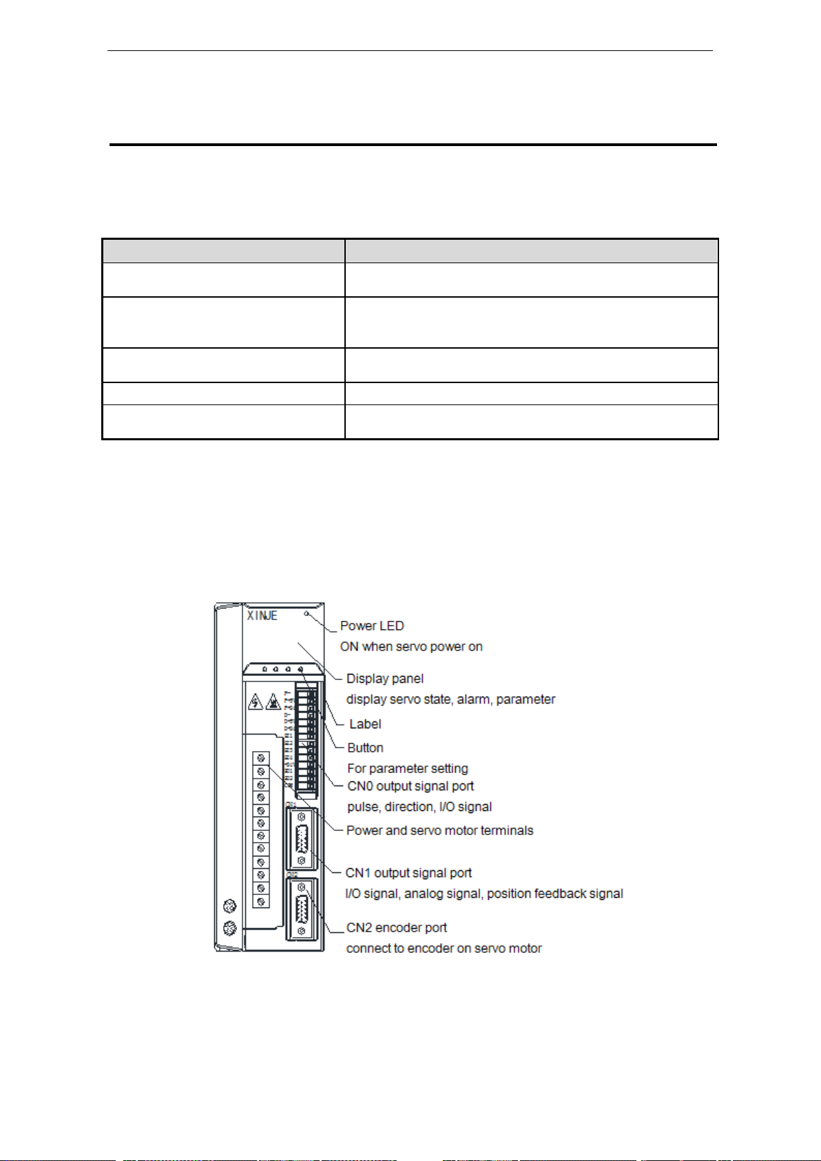
1 Checking Product and Part Names
1-1.Checking Products on Delivery
Use the following checklist when products are delivered.
If any of the above is faulty or incorrect, contact Xinje or an authorized distributor.
1-2.Product appearance and name rule
DS3-2□P□-PQA/ DS3-4□P□-PQA/ DS3E-2□P□-PFA/ DS3E-4□P□-PFA
Appearance and nameplate
8
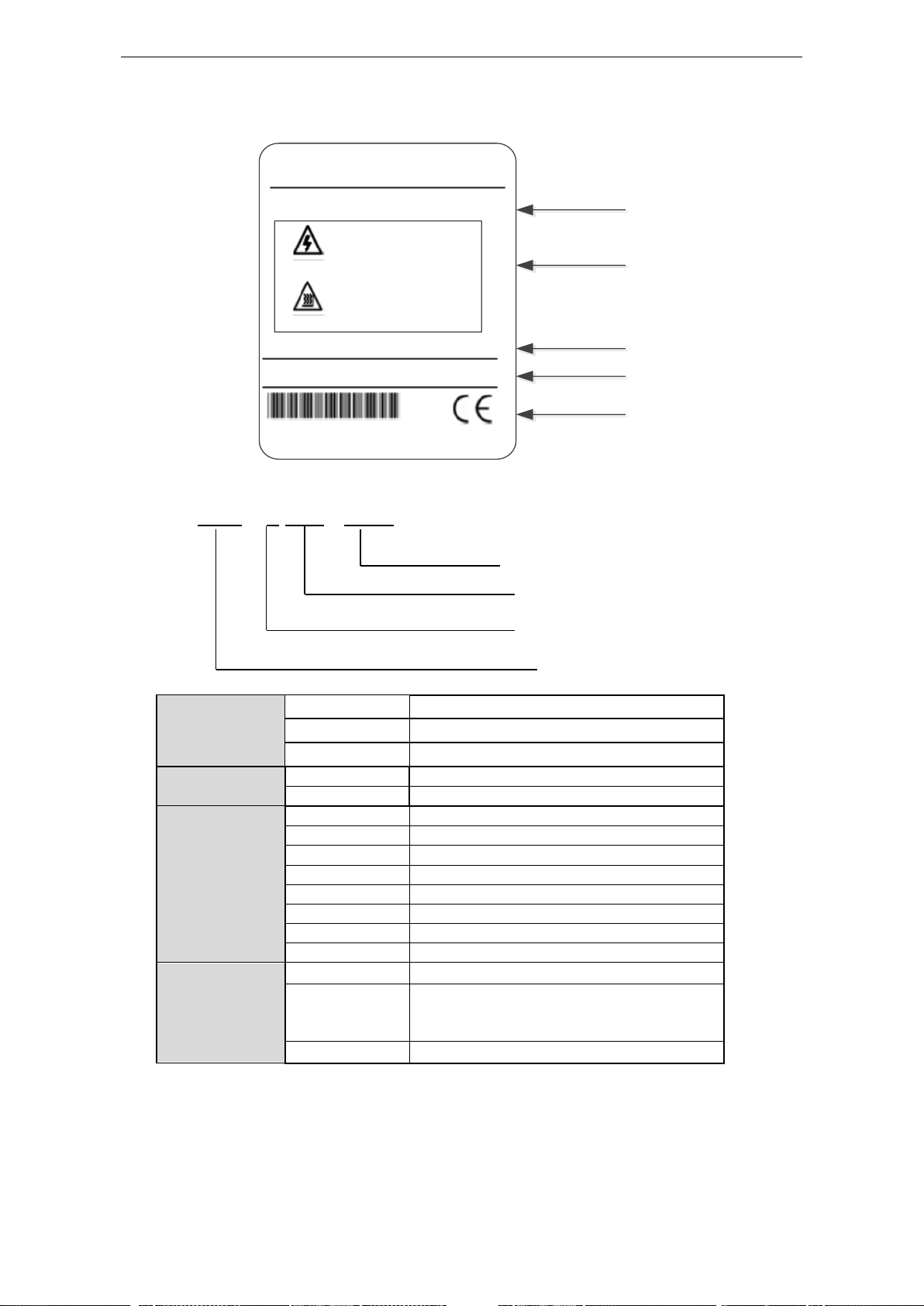
Servo drive nameplate
Series
DS3
DS3 series high precision servo drive
DS3E
DS3E series filedbus servo drive
DS3L series pulse-type servo drive
Voltage level
2
220V
4
380V
Suitable motor
capacity
0P2
0.2 KW
0P4
0.4KW
0P7
0.75KW
1P5
1.5KW
2P3
2.3KW
3P0
3.0KW
5P5
5.5KW
7P5
7.5KW
Configuration
type
P
Input command type: pulse
Encoder type
Q-quadrature encoder
F-compatible quadrature encoder
T-17 bits absolute value encoder
A
Design order: A
Configure type
Series name
Suitable motor capacity
Voltage level
XINJE
SERVO DRIVER
DS3-20P7-PQA
WARNING
CAUTION
AC INPUT:1PH/3PH 200-240V 50/60Hz 3.5A
AC OUTPUT:3PH 0-200V 3.5A 0.75KW
12052013
WUXI XINJE ELECTRIC CO.,LTD
Drive model
Caution
Input power supply
Output power supply
Serial no.
(1) Naming rule
DS3 – 2 0P7 - PQA
9
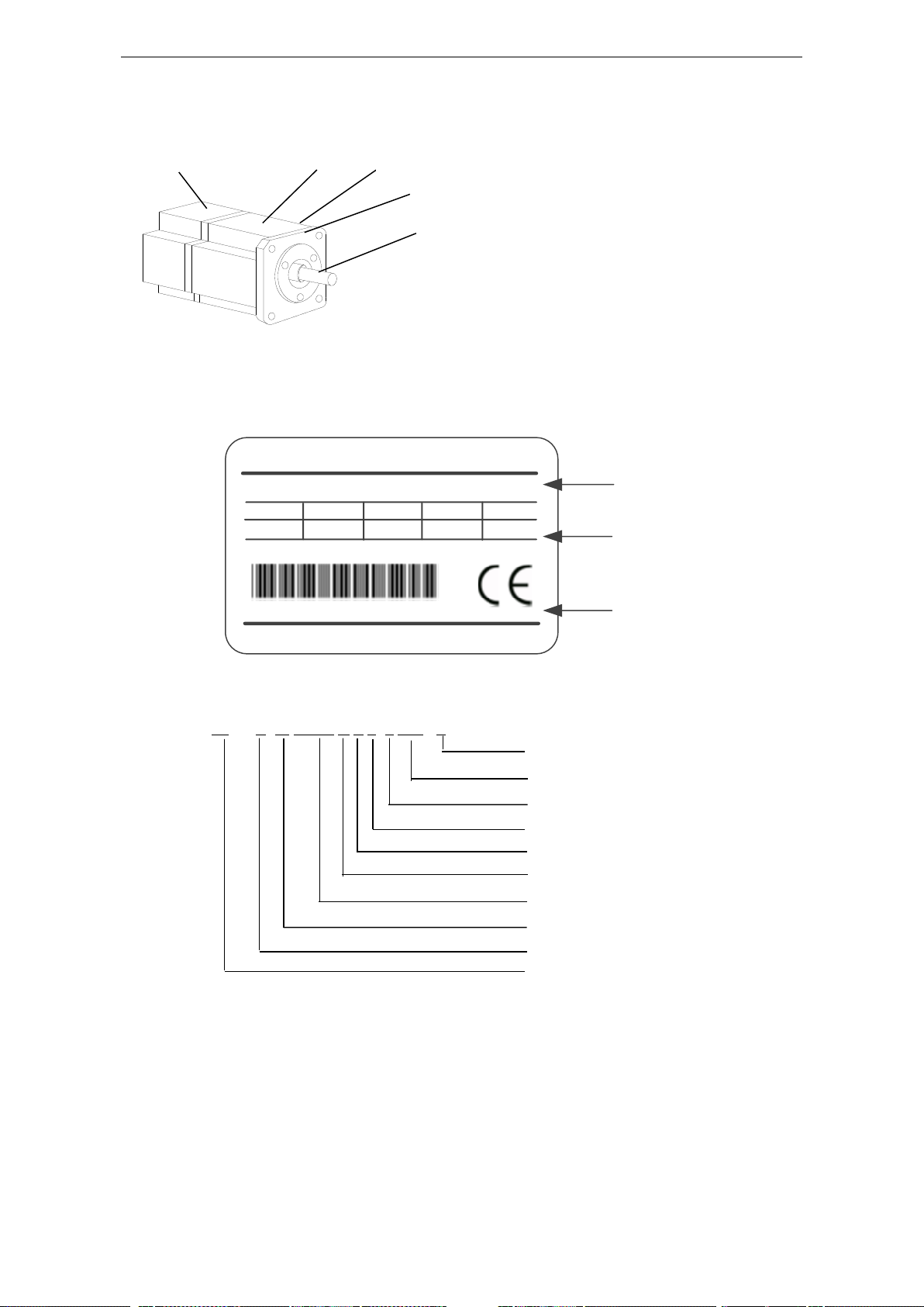
Servo motor
Encoder part
Frame
Flange
Output (transmission) shaft
Motor label
XINJE
AS SERVO MOTOR
MS- 80ST- M02403B -20P7
0.75
XJY1410714180480701
Motor model
Motor
specification
Serial no.
KW
IP
65
MOTOR CODE:1011
WUXI XINJE ELECTRIC CO.,LTD
N M
A
rpm
30003.2
2.39
Shaft length
power
voltage level
body length
power-loss brake
shaft specification
performance parameter code
feedback component code
oil seal
base no.
(1) Appearance and nameplate
Motor label
(2) Naming rule
MS -80 ST E- M 02430 B Z S- 2 0P7 - S

10
Base number
40, 60, 80, 90, 110, 130, 180, 220
Oil seal
Empty
Without oil seal (130ST and above models all
have oil seal, so the model without E)
E
With oil seal (60ST, 80ST model name has
differences)
Feedback
component no.
M
Incremental encoder (2500ppr optical pulse
encoder)
F
Line-saving incremental encoder (2500ppr
optical pulse encoder)
T
17 bits absolute value encoder
N
20 bits absolute value encoder
Performance
parameter no.
First 3 bits mean rated torque, last 2 bits mean rated speed
Such as: 00630: rated torque 0.6N.m, rated speed 3000rpm
06025: rated torque 6.0N.m, rated speed 2500rpm
19015: rated torque 19.0N.m, rated speed 1500rpm
Shaft spec
A
No bond
B
With bond
Power-loss
brake
Vacant
No
Z
With power-off brake
Body length
Vacant
Normal models
S
Short body
Voltage level
2
220V
4
380V
Power
Such as: 0P4: 0.4kW
0P7: 0.75kW
1P5: 1.5KW
Motor shaft
length
Note: only
180ST has
differences
vacant
Normal models
S
Short shaft

11
2 Installations
CAUTION
1. The end of the motor shaft is coated with antirust. Before installing, carefully remove all of the
paint using a cloth moistened with paint thinner.
2. Avoid getting thinner on other parts of the servomotor.
Antirust
2-1.Servo motor
MS series servomotors can be installed either horizontally or vertically. The service life of the
servomotor can be shortened or unexpected problems might occur if it is installed incorrectly or in an
inappropriate location. Follow these installation instructions carefully.
2-1-1.Storage Temperature
Store the servomotor within -20~+60 ℃ as long as it is stored with the power cable disconnected.
2-1-2.Installation Site
MS series servomotors are designed for indoor use. Install the servomotor in environments that satisfy
the following conditions.
Free of corrosive or explosive gases.
Well-ventilated and free of dust and moisture.
Ambient temperature of 0° to 50°C.
Relative humidity (r.h.) of 20 to 90% with no condensation.
Accessible for inspection and cleaning.
2-1-3.Concentricity
Please use coupling when connecting to machine; keep the shaft center of servo motor and machine at
the same line. It should be accord to the following diagram when installing the servo motor.

12
Situation
Installation Precaution
Installation in a Control
Panel
Design the control panel size, unit layout, and cooling method so the
temperature around the servo drives does not exceed 50°C.
Through part of the shaft
Measure it at 4 places of the circle, the difference should be below
0.03mm. (Rotate with the shaft coupler)
Measure it at 4 places of the circle, the difference should be below 0.03mm.
(Rotate with the shaft coupler)
Note: (1) If the concentricity is not enough, it will cause the vibration and bearing damage.
(2) When installing the coupler, prevent direct impact to the shaft. This can damage the encoder
mounted on the shaft end at the opposite side of the load.
2-1-4.Orientation
MS series servomotors can be installed either horizontally or vertically.
2-1-5.Handling Oil and Water
Install a protective cover over the servomotor if it is used in a location that is subject to water or oil
mist. Also use a servomotor with an oil seal when needed to seal the through-shaft section.
2-1-6.Cable Stress
Make sure that the power lines are free from bends and tension. Be especially careful to wire signal line
cables so that they are not subject to stress because the core wires are very thin, measuring only 0.2 to
0.3mm2.
2-2.Servo Drive
The DS3 series PQA servo drives are base-type servo drive. Incorrect installation will cause problems.
Follow the installation instructions below
2-2-1.Storage Conditions
Store the servo drive within -20~+60℃, as long as it is stored with the power cable disconnected.
2-2-2.Installation Site
The following precautions apply to the installation site.

13
Installation Near a
Heating Unit
Minimize heat radiated from the heating unit as well as any temperature
rise caused by natural convection so the temperature around the servo
drives does not exceed 50°C.
Installation Near a Source
of Vibration
Install a vibration isolator beneath the servo drive to avoid subjecting it to
vibration.
Installation at a Site
Exposed to Corrosive Gas
Corrosive gas does not have an immediate effect on the servo drives, but
will eventually cause electronic components and terminals to malfunction.
Take appropriate action to avoid corrosive gas.
Other Situations
Do not install the servo drive in hot and humid locations or locations
subject to excessive dust or iron powder in the air.
2-2-3.Orientation
Install the servo drive perpendicular to the wall as shown in the figure. The servo drive must be
oriented this way because it is designed to be cooled by natural convection or by a cooling fan.
2-2-4.Installation
Follow the procedure below to install multiple servo drives side by side in a control panel.

14
Servo Drive Orientation
Install the servo drive perpendicular to the wall so the front panel containing connectors faces outward.
Cooling
As shown in the figure above, allow sufficient space around each servo drive for cooling by cooling
fans or natural convection.
Side-by-side Installation
When install servo drives side by side as shown in the figure above, make at least 10mm between and
at least 50mm above and below each servo drive. Install cooling fans above the servo drives to avoid
excessive temperature rise and to maintain even temperature inside the control panel.
Environmental Conditions in the Control Panel
Ambient Temperature: 0~50 ℃
Humidity: 90%RH or less
Vibration: 4.9m/s2
Condensation and Freezing: None
Ambient Temperature for Long-term Reliability: 50°C maximum

15
3 Wiring
Servo drive
Power supply
cable diameter
mm²
UVW power cable
diameter mm²
Encoder cable
diameter mm²
Ground cable
diameter mm²
DS3-20P2-PQA
DS3E-20P2-PFA
DS3L-20P2-PFA
DS3-20P2-PTA
2.0
0.75
0.2 (14 cores)
2.0
DS3-20P4-PQA
DS3E-20P4-PFA
DS3L-20P4-PFA
DS3-20P4-PTA
2.0
0.75
0.2 (14 cores)
2.0
DS3-20P7-PQA
DS3E-20P7-PFA
DS3L-20P7-PFA
DS3-20P7-PTA
2.0
0.75
0.2 (14 cores)
2.0
DS3-21P5-PQA
DS3E-21P5-PFA
DS3L-21P5-PFA
DS3-21P5-PTA
2.0
1.5
0.2 (14 cores)
2.0
DS3-22P3-PQA
DS3E-22P3-PFA
DS3L-22P3-PFA
DS3-22P3-PTA
2.0
1.5
0.2 (14 cores)
2.0
DS3E-22P6-PFA
DS3L-22P6-PFA
2.0
1.5
0.2 (14 cores)
2.0
DS3-41P5-PQA
DS3E-41P5-PFA
DS3L-41P5-PFA
DS3-41P5-PTA
2.0
1.5
0.2 (14 cores)
2.0
DS3-43P0-PQA
DS3E-43P0-PFA
DS3L-43P0-PFA
DS3-43P0-PTA
2.0
2.5
0.2 (14 cores)
2.0
DS3-45P5-PQA
DS3L-45P5-PQA
DS3-47P5-PQA
DS3L-47P5-PQA
6.0
6.0
0.2 (14 cores)
6.0
DS3-411P0-PQA
DS3-415P0-PQA
10.0
10.0
0.2 (9 cores)
10.0
Caution
1. Do not bundle or run power and signal lines together in the same duct. Keep power and signal
lines separated by at least 11.81inch(30cm)
2. Use twisted pair wires or multi-core shielded-pair wires for signal and encoder (PG) feedback
lines.
The maximum length is 118.11 inch (3m) for reference input lines and is 787.40 inch (20m) for
encoder (PG) feedback lines.
3. Do not touch the power terminals for 5 minutes after turning power OFF because high voltage
may still remain in the servo amplifier.
Please make sure to check the wiring after the CHARGE light is going off.
4. Avoid frequently turning power ON and OFF. Do not turn power ON or OFF more than once per
Servo drive cable table:
16
minute.
Since the servo amplifier has a capacitor in the power supply, a high charging current flows for
0.2s when power is turned ON. Frequently turning power ON and OFF causes main power devices
like capacitors and fuses to deteriorate, resulting in unexpected problems.
3-1.DS3-PQA series
3-1-1.Main circuit wiring
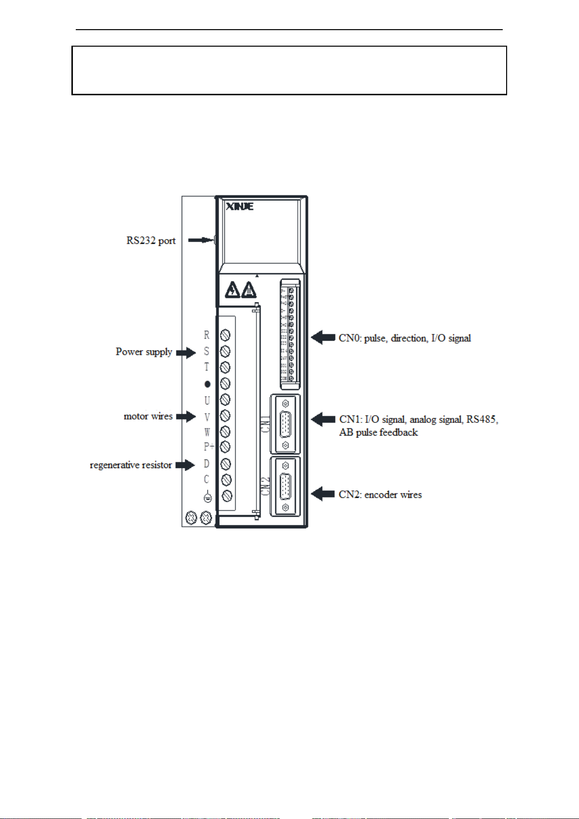
3-1-1-1. Servo drive terminal arrangement
17
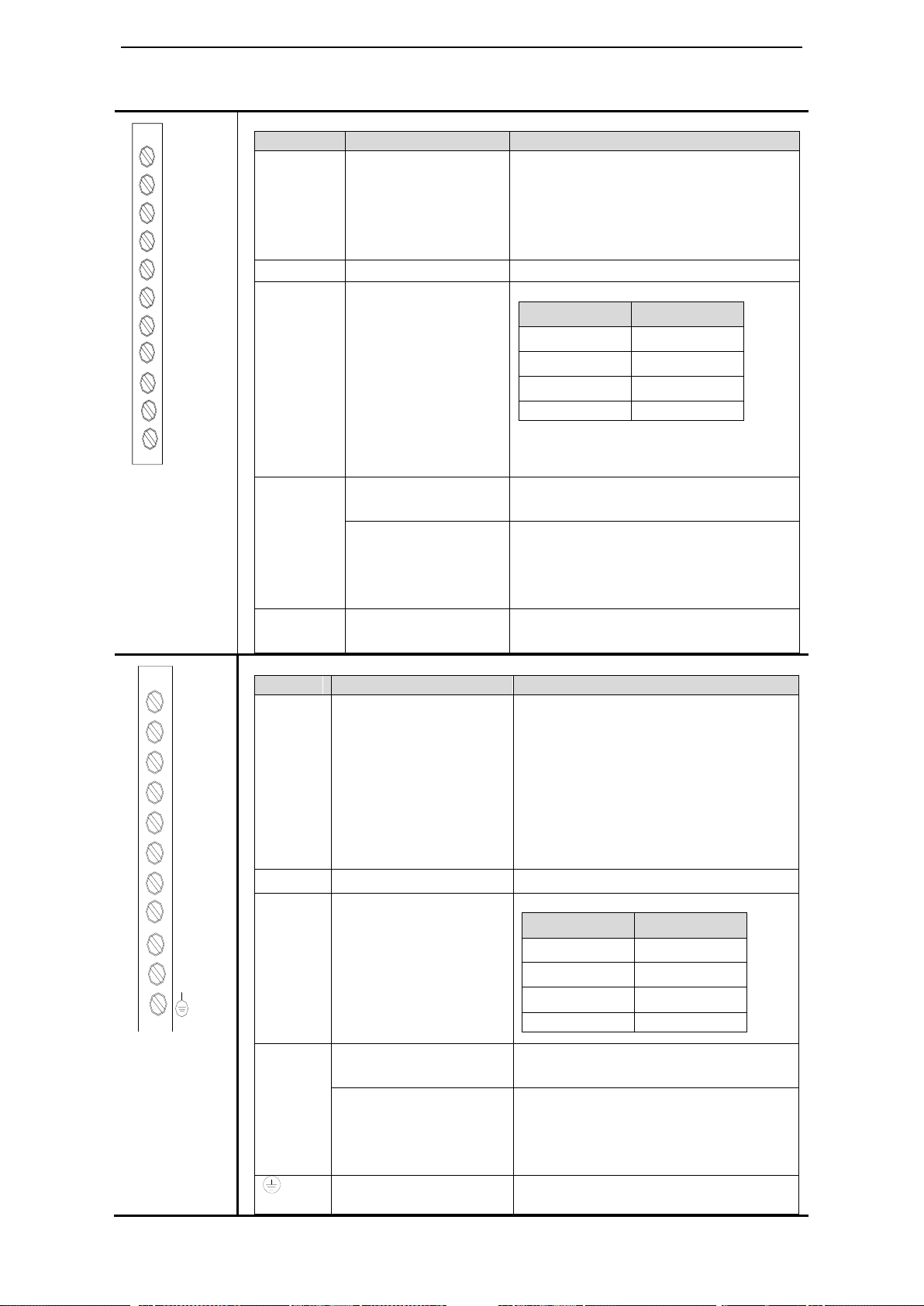
3-1-1-2. Main circuit terminals
DS3-20P2-PQA, DS3-20P4-PQA, DS3-20P7-PQA
Terminal
Function
Explanation
L1/L2/L3
Power supply input of
main circuit
Single or 3 phase AC 200 ~ 240V,
50/60Hz
Note: for single phase 220V, connect
power supply to L1, L3, otherwise it will
affect the power-off retentive function
●
Vacant terminal
-
U, V, W
Motor terminals
Connect the motor
Terminal
Color
U
brown
V
black
W
blue
PE
Yellow green
Note: the ground line is on the cooling
fin, please check it before power on! Do
not connect to P+ or P-!
P+, D, C
Internal regenerative
resistor
Short P+ and D, disconnect P+ and C, set
P0-24=0
External regenerative
resistor
Connect regenerative resistor between P+
and C, disconnect P+ and D, set P0-24=1,
P0-25= power value, P0-26= resistor
value (see chapter 3-4)
P+/P-
Bus terminal
Real-time check the bus voltage, please
take attention of this terminal
DS3-21P5-PQA, DS3-22P3-PQA, DS3-41P5-PQA
Terminal
Function
Explanation
R/S/T
Power supply input of
main circuit
DS3-21P5/22P3-PQA
3 phase AC 200~240V, 50/60Hz
Note: for single phase 220V, connect
power supply to terminal R, T, otherwise
it will affect the power-off retentive
function.
DS3-41P5-PQA
3 phase AC 360~400V, 50/60Hz
●
Vacant
-
U, V, W
Motor terminals
Connect the motor
Terminal
Color
U
brown
V
black
W
blue
PE
Yellow green
P+, D, C
Internal regenerative
resistor
Short P+ and D, disconnect P+ and C,
set P0-24=0
External regenerative
resistor
Connect regenerative resistor between
P+ and C, disconnect P+ and D, set
P0-24=1, P0-25=power value,
P0-26=resistor value (see chapter 3-1-4)
Ground
Connect to ground terminal of motor,
then connect to the ground
L1
L2
.
U
V
W
P+
D
C
P-
L3
R
S
T
.
U
V
W
P+
D
C
18
DS3-43P0-PQA
Terminal
Function
Explanation
R/S/T
Power supply input of
main circuit
3 phase AC 360~400V, 50/60Hz
●
Vacant
U、V、
W
Motor terminals
Connect the motor
Terminal
Color
U
brown
V
black
W
blue
PE
Yellow green
Note: the ground line is on the cooling
fin, please check it before power on! Do
not connect to P+ or P-!
P+、D、
C
Internal regenerative
resistor
Short P+ and D, disconnect P+ and C,
set P0-24=0
External regenerative
resistor
Connect regenerative resistor between
P+ and C, disconnect P+ and D, set
P0-24=1, P0-25=power value,
P0-26=resistor value (see chapter 3-1-4)
P+/P-
Bus terminal
Real-time check the bus voltage, please
take attention of this terminal
Symbol
40, 60, 80, 90 Series
110, 130, 180 Series
PE
4-yellow green (yellow green)
1-yellow green
U
1-brown (red)
2-brown
V
3-black (blue)
3-black
W
2-blue (yellow)
4-blue
Terminal for brake
1: +24V
2: GND
CN0
CN1(DB15 male port) drive
side
CN2(DB15 female port)
drive side
R
S
T
.
U
V
W
P+
D
C
P-
.
PP+5V
P+24V
DD+5V
D+24V
SI1
SI2
SI3
SI4
+24V
SO1
SO2
COM
1
5
6
10
11
15
5
1
10
6
15
11
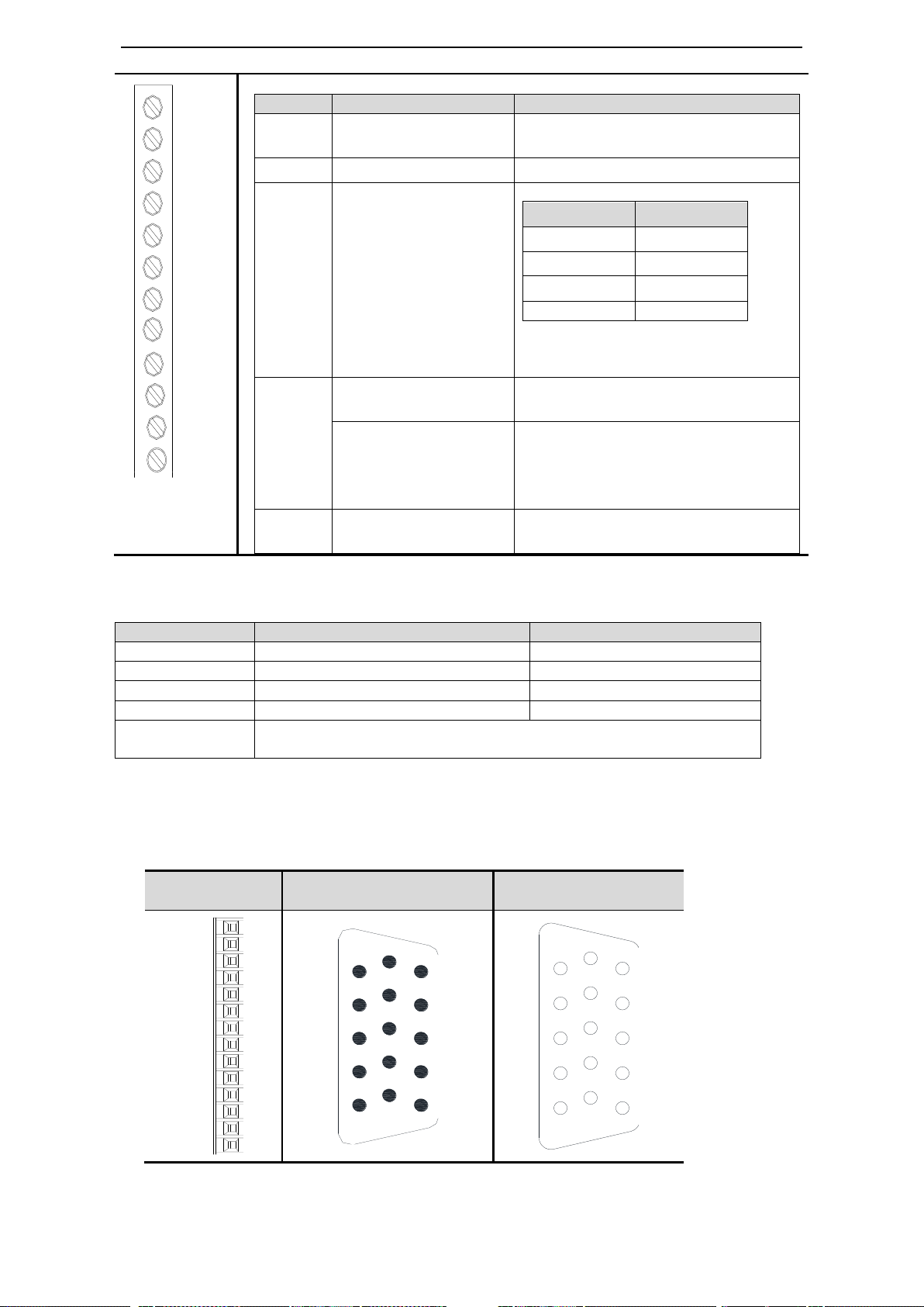
3-1-1-3.Winding Terminals on Servo motor
3-1-1-4.CN0, CN1, CN2 terminals
19
No.
Name
Explanation
No.
Name
Explanation
1
P-
Pulse input PUL-
8
SI2
Input 2
2
P+5V
5V difference input
9
SI3
Input 3
3
P+24V
Open collector input
10
SI4
Input 4
4
D-
Direction input DIR-
11
+24V
Input +24V
5
D+5V
5V difference input
12
SO1
Output 1
6
D+24V
Open collector input
13
SO2
Output 2
7
SI1
Input 1
14
COM
Ground of output
No.
Name
Explanation
No.
Name
Explanation
1
GND
GND-485
9
Z-
Encoder output Z-
2
A1
RS485+
10
B+
Encoder output B+
3
B1
RS485-
11
T-REF
Torque analog input
4
VCC
VCC-RS485
12
V-REF
Speed analog input
5
B-
Encoder output B-
13
GND
GND for analog input
6
A+
Encoder output A+
14
A2
RS485+
7
A-
Encoder output A-
15
B2
RS485-
8
Z+
Encoder output Z+
No.
Name
Explanation
No.
Name
Explanation
1
NC
Reserved
9
Z-
Encoder output Z-
2
NC
Reserved
10
B+
Encoder output B+
3
SI5
Input 5
11
T-REF
Torque analog input
4
SO3
Output 3
12
V-REF
Speed analog input
5
B-
Encoder output B-
13
GND
GND for analog input
6
A+
Encoder output A+
14
A
RS485+
7
A-
Encoder output A-
15
B
RS485-
8
Z+
Encoder output Z+
No.
Name
Explanation
No.
Name
Explanation
1
GND
GND-485
2
A1
RS485+
3
B1
RS485-
4
A2
RS485+
5
B2
RS485-
6
GND
GND-485
7
NC
Reserved
8
NC
Reserved
9
NC
Reserved
Drive
port
Motor encoder port
Name
Drive
port
Motor encoder port
Name
60, 80, 90
series
110, 130, 180
series
60, 80, 90
series
110, 130, 180
series
1 9 4
A+ 2 4
5
B+
3 7 6
Z+ 4 6
10
U+ 5 11
12
W+ 6 13
7
A- 7 14
8
B- 8 5
9
Z-
CN0 terminals
CN1 (DB15) terminals
DS3 series 750W and below servo drive (hardware version v3.1.20)
DS3 series above 750W servo drive
DS3 series 5.5KW and 7.5KW servo drive (only these two models use 9-pin port)
CN2 terminals
20
9 8 13
U-
10
15
15
W-
11 1 1
Connect
to shield
layer
12 3 3
GND
13 2 2
5V
14
10
11
V+
15
12
14
V-
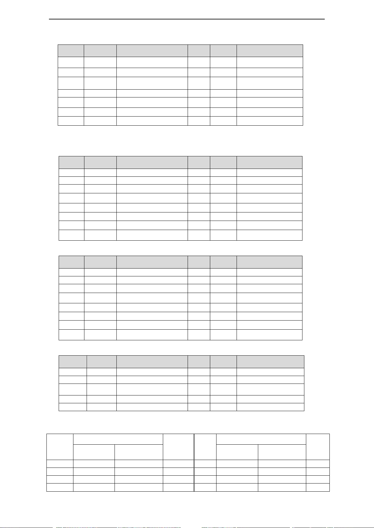
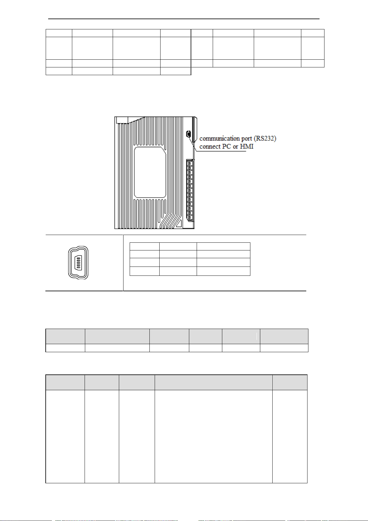
(5-pin port)
Pin no.
Name
Explanation
1
TXD
RS232 send
2
RXD
RS232 receive
3
GND
RS232 ground
Parameter
Function
Default
setting
Range
Modify
Effective
P7-10
Modbus station no.
1
1~255
Servo OFF
At once
Parameter
no.
Function
Default
value
Range
Effective
time
n.xx□□
Baud rate
06
00~10
00:300
01:600
02:1200
03:2400
04:4800
05:9600
06:19200
07:38400
08:57600
09:115200
At once
1
5
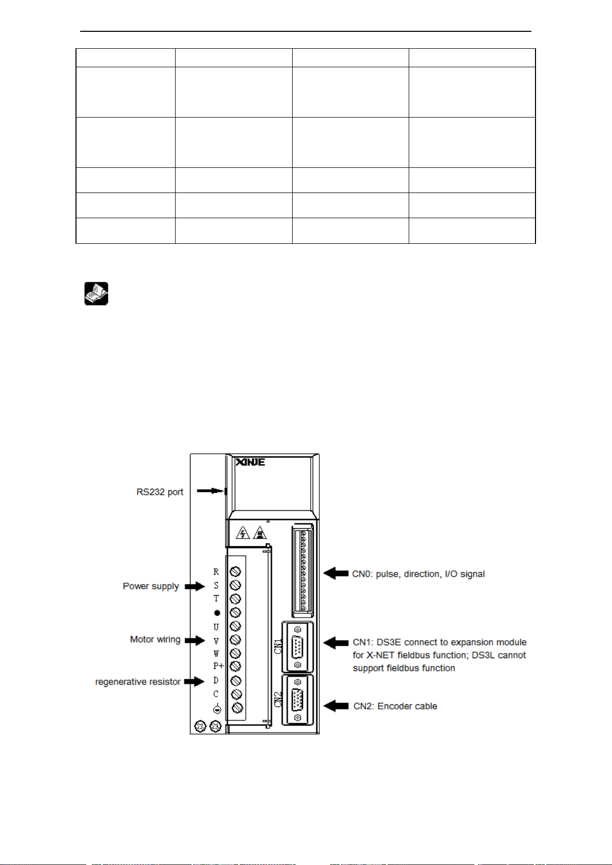
3-1-1-5. Communication port
RS-232 communication
Note: please use the cable supplied by XINJE Company
Communication parameters:
RS232 default communication parameters: baud rate 19200bps, data bit 8, stop bit 1, even parity.
Modbus station no. setting:
Please set the following parameters through P7-11:

21
0A:192000
0B:256000
0C:288000
0D:384000
0E:512000
0F:576000
10:768000
n.x□xx
Stop bit
2
0:2 bits, 2:1 bit
At once
n.□xxx
Parity bit
2
0~2
0:no parity, 1: odd parity, 2: even parity
At once
Note: data bit cannot be changed, it is 8 bits.
Pin no.
Name
CN1-14
A
CN1-15
B
Parameter
Function
Default value
Range
Effective time
P7-00
Modbus station no.
1
0~255
At once
Parameter
Function
Default value
Range
Effective
time
n.xx□□
Baud rate
06
00~10
00:300
01:600
02:1200
03:2400
04:4800
05:9600
06:19200
07:38400
08:57600
09:115200
0A:192000
0B:256000
0C:288000
0D:384000
0E:512000
0F:576000
10:768000
11:1M
12:2M
13:3M
14:4M
15:5M
At once
910
15 14 13
12
11
1
2
345
6
7
8
RS-485 port
Communication parameters:
RS485 default communication parameters: baud rate 19200bps, data bit 8, stop bit 1, even parity,
Modbus station no.1.
The Modbus station no. can be set through P7-00:
The communication parameters can be set through P7-01:
22
16:6M
n.x□xx
Stop bit
2
0:2 bits, 2:1 bit
At once
n.□xxx
Parity bit
2
0~2
0:no parity, 1: odd parity, 2: even
parity
At once
Note: data bit cannot be changed, it is 8 bits.
Parameter
Function
Default
setting
Range
Modify
Effective
P7-02
RS485
communication
protocol
1
1: Modbus Rtu protocol
2: Xnet filedbus protocol
Servo OFF
At once
Command
Choice
Meaning
P-input signal
D-input signal
Chapter
P0-10
xxx□
0
CW, CCW double pulse
mode
CW
CCW
5-3-2
1
AB phase mode
A phase
B phase
2
Pulse + direction mode
Pulse
Direction
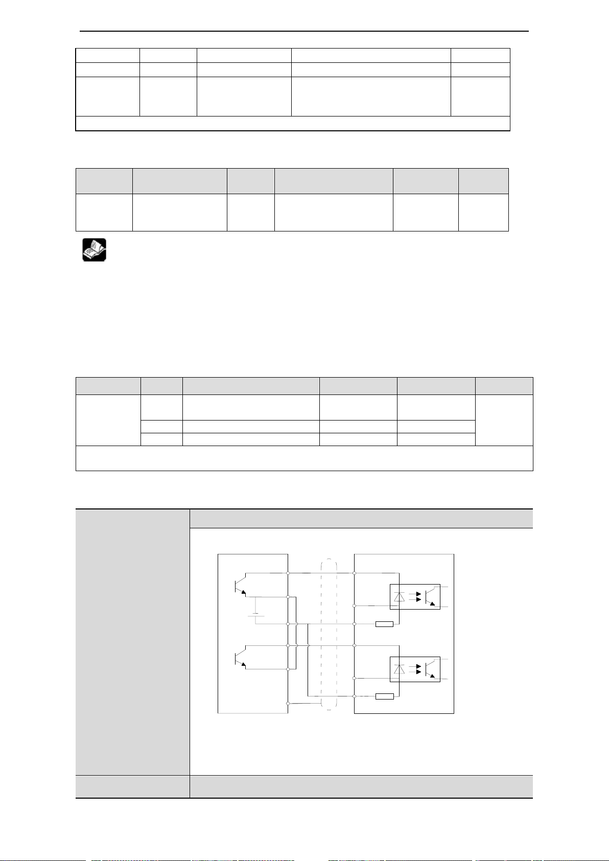
Collector open circuit (24V) input positive signal: P+24V/D+24V
Differential mode (5V) input positive signal: P+5V/D+5V
DS3-2□P□-PQA
DS3-4□P□-PQA
Open collector (24V)
PLC, SCM, etc servo drive
Note:
(1) P-/P+24V, D-/D+24V power supply range is 18~25V. if the voltage
is lower than 18V, the pulse and direction will be error.
(2) To avoid the interference, please use shielded twisted-pair cable.
DS3-2□P□-PQA
Differential mode (5V)
COM0
Y0
+24V
P-
R=3.3K
COM1
Y1
D-
R=3.3K
P+5V
D+5V
Shield layer
0V
D+24V
P+24V
When upper
device is open
collector output,
please use this
wiring diagram.
Please note:
P+5V and
D+5V must be
vacant.
P7-02 RS485 communication protocol setting:
1. Support standard Modbus RTU protocol, it is used as Modbus slave device.
2. RS232 port and RS485 port can be used at the same time.
3-1-2.Signal terminals
3-1-2-1. Pulse signal
The interface circuit of Pulse + direction and CW, CCW mode:
23
DS3-4□P□-PQA
PLC, SCM, etc servo drive
To avoid the interference, please use shielded twisted-pair cable.
Type
Input terminal
Function
Reference chapter
Digital input
SI1~SI5
Multi-functional input
5-12-1
Open collector (24V power supply)
Relay (24V power supply)
Upper device servo drive
Upper device servo drive
Type
Output
terminal
Function
Reference chapter
Optocoupler
output
SO1~SO3
Multiple functions output terminal
5-12-3
SI
+24V
+
COM2
Y2
0V
+24V
R=2.2KΩ
R=2.2KΩ
+24V
0V
Y2
COM2
+
+24V
SI
P+24V
PUL+
PUL-
P-
R=3.3K
DIR-
D-
R=3.3K
P+5V
D+5V
Shield layer
0V
D+24V
DIR+
When upper
device is 5V
differential
output, please
use this wiring
diagram. Please
note: P+24V
and D+24V
must be vacant.
(1) Servo pulse input will be ON at 10mA.
(2) If the controller is XINJE PLC, pulse output rated current is 50mA, so 1 channel of pulse can
connect 5 servo drives. We suggest not over 3 servo drives.
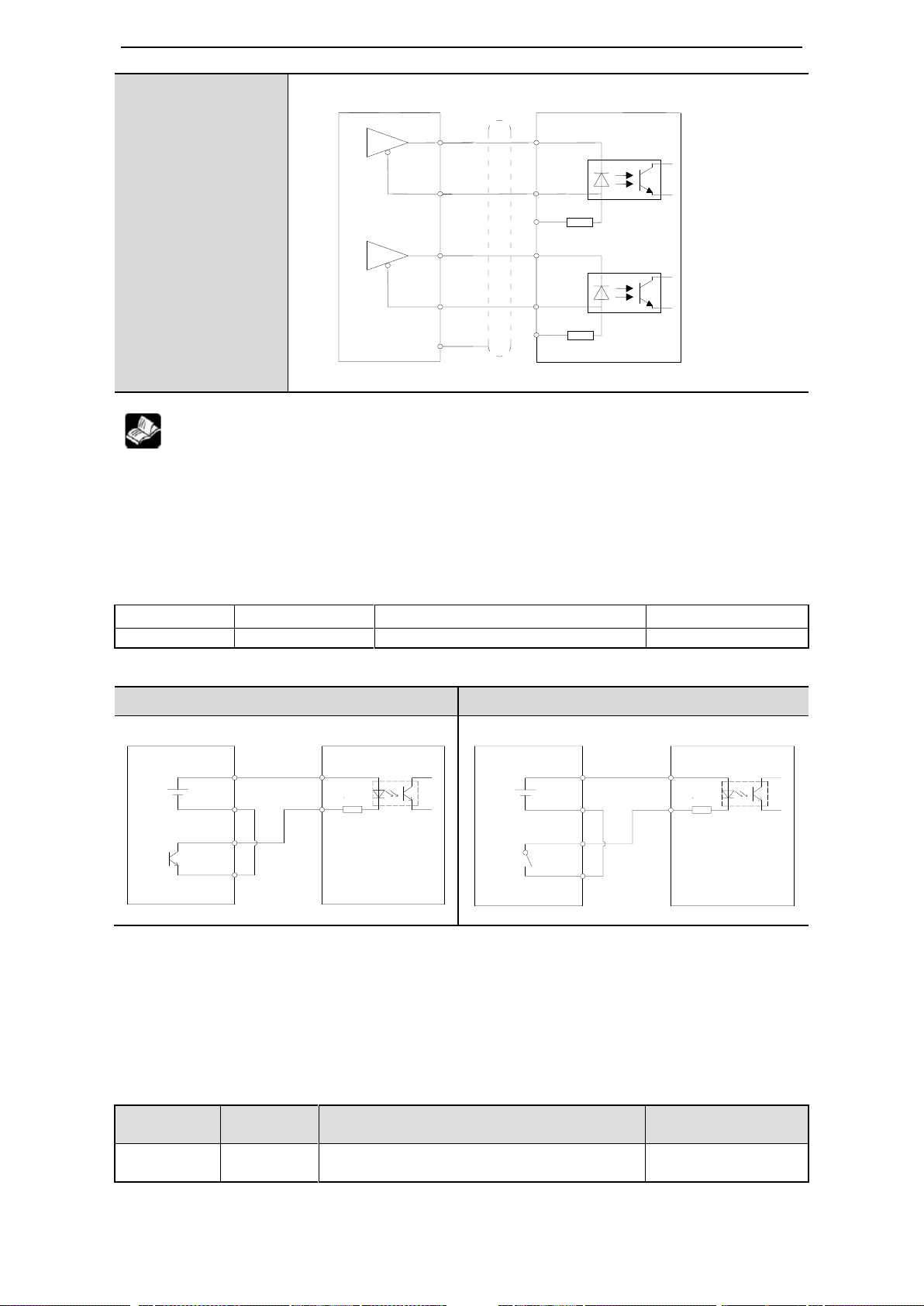
3-1-2-2.SI input signal
Please use relay or open collector transistor to connect. When using relay, please choose micro-current
relay. Otherwise, the contact will be not good.
Note: the max allowable voltage and current of open collector output circuit:
Voltage: max DC30V
Current: max DC50mA
3-1-2-3. SO output signal
24
Optocoupler type
Servo drive upper device
Relay type
Servo drive upper device
DS3-2□P□-PQA
DS3-4□P□-PQA
Upper device servo drive
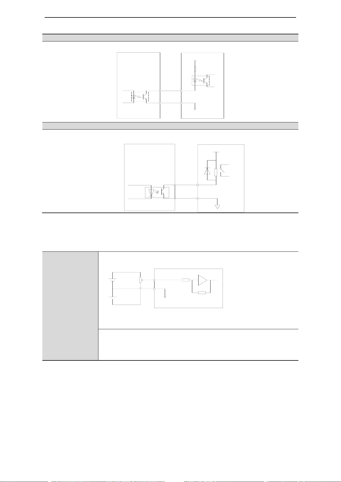
Note: analog terminal 11 (T-REF analog torque), 12(T-REF analog speed),
13(analog GND) come from CN1 DB15, refer to chapter 3-1-1-4.
Analog signal is speed command or torque command. Input impedance:
• speed command input: about 13KΩ
• torque command input: about 13KΩ
• max allowable voltage of input signal is ±10V
COM
SO
X3
COM
0V
+24V
+10V
-10V
11 T-REF
12 V-REF
13 GND
0V
R=13KΩ
2KΩ
1W
Note: max load current 400mA (if control the brake motor by SO signal, please confirm the
brake current, if it is larger than 400mA, please use intermediate relay)
3-1-2-4. Analog input circuit
25
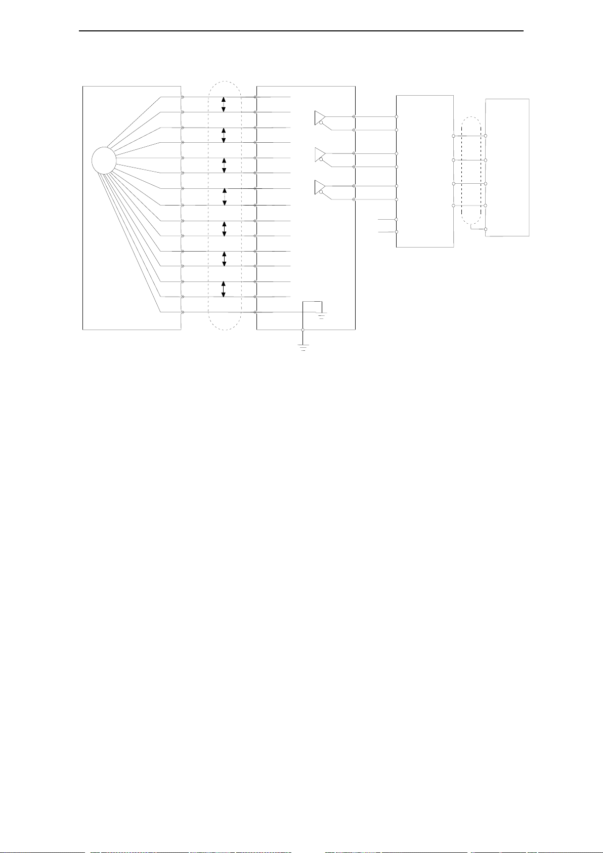
3-1-2-5. Encoder feedback signal
PG
A+
A-
B+
B-
Z+
Z-
U+
U-
V+
V-
W+
W-
+5V
GND
SHIELD
cover
A+
A-
B+
B-
Z+
Z-
U+
U-
V+
V-
W+
W-
+5V
GND
Connector cover
CN2
AO+
AO-
BO+
BO-
ZO+
ZO-
0V
24V
AO+
AO-
BO+
BO-
ZO+
ZO-
X0
X1
X2
COM
Incremental encoder
Upper device
0V
Shield cable
Shiled layer
COM
Z B A
Servo unit
Differential to collector
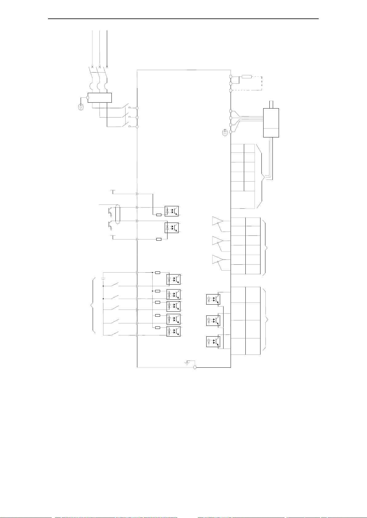
3-1-3. Standard wiring example
For the following wiring diagram, the input and output terminal function is out of factory settings. The
setting can be changed, please see chapter 5-12.
3-1-3-1.Position Control Mode
DS3-21P5-PQA
26
CN0-11
A0-
AO+
COM
Shield layer connect
0V at signal side
Be vacant at
Drive side
Vcc
CN0-1
2.2
Ω
W
V
DS3-21P5-PQA,DS3-22P3-PQA: 3-phase AC220V (50/60Hz)
DS3-4□P□-PQA: 3-phase AC380V (50/60Hz)
CN2
R
S-RDY
ALM
COIN
FIL
Self-define the
Terminals function
CN0-8
CN0-7
/S-ON
+24VIN
U
S
T
CN0-10
/N-OT
/ALM-RST
3.3KΩ
P+24V
CN0-3
Vcc
2.2
Ω
CN1-5
CN1-10
B0-
BO+
CN1-9
CN1-8
Z0-
ZO+
C
D
P+
Servo motor
Encoder
CN2-5
W+
CN2-4
CN2-3
U+
Z+
CN2-2
CN2-1
B+
A+
.
. . .
.
.
Differential encoder
feedback
Self-define
the terminals
function
D+24V
D-
P-
CN0-6
CN0-4
CN1-7
CN1-6
CN0-14
CN1-4
CN0-13
CN0-12
CN1-3
CN0-9
/P-OT
/SPD-A
Regenerative resistor

27
3-1-4.Regenerative Resistor
Servo drive
Regenerative resistor connection terminals
DS3-2□P□-PQA
DS3-4□P□-PQA
DS3E-2□P□-PFA
DS3E-4□P□-PFA
DS3L-2□P□-PFA
DS3L-4□P□-PFA
DS3-2□P□-PTA
DS3-4□P□-PTA
for internal regenerative resistor: short P+ and D, disconnect P+ and C,
P0-24=0.
for external regenerative resistor: connect resistor between P+ and C,
disconnect P+ and D, P0-24=1, P0-25=power value, P0-26=resistor value.
Parameter
Signal name
Setting
Meaning
Effective
Modify
P0-24
Choose
regenerative
resistor
0
Use internal regenerative resistor
At once
Servo OFF
1
Use external regenerative resistor
(resistor type please refer to the
following table)
Parameter
Signal name
Setting
Unit
Effective
P0-25
Discharge
resistor power
1. self-cooling mode (natural convection cooling):
below 20% of regenerative resistor capacity (W)
2. forced air cooling: below 50% of regenerative
resistor capacity (W)
W
At once
P0-26
Discharge
resistor value
Resistor value
Ω
At once
Servo drive
Min resistor
(cannot smaller than
this value)
External regenerative
resistor (recommend
value)
External regenerative
resistor (recommend
power)
DS3-20P2-PQA
DS3E-20P2-PFA
DS3L-20P2-PFA
DS3-20P2-PTA
50Ω
50Ω—100Ω
Above 200W
DS3-20P4-PQA
DS3E-20P4-PFA
DS3L-20P4-PFA
DS3-20P4-PTA
40Ω
40Ω—100Ω
Above 500W
DS3-20P7-PQA
DS3E-20P7-PFA
DS3L-20P7-PFA
DS3-20P7-PTA
40Ω
40Ω—100Ω
Above 500W
DS3-21P5-PQA
DS3E-21P5-PFA
DS3L-21P5-PFA
DS3-21P5-PTA
25Ω
25Ω—50Ω
Above 1000W
DS3-22P3-PQA
DS3E-22P3-PFA
DS3L-22P3-PFA
25Ω
25Ω—50Ω
Above 1000W
When the servo motor operates in generator mode, power is returned to the servo drive side. This is
called regenerative power. The regenerative power is absorbed by charging the smoothing capacitor,
but when the capacitor’s charging limit is exceeded, the regenerative power needs to be reduced by the
regenerative resistor.
The servomotor is driven in regeneration (generator) mode in the following conditions:
From decelerating to stop for acceleration/deceleration operation.
Move down on the vertical axis.
The external load drives the motor running
The type of regenerative resistor:
28
DS3-22P3-PTA
DS3-41P5-PQA
DS3E-41P5-PFA
DS3L-41P5-PFA
DS3-41P5-PTA
55Ω
55Ω—100Ω
Above 1000W
DS3-43P0-PQA
DS3E-43P0-PFA
DS3L-43P0-PFA
DS3-43P0-PTA
55Ω
55Ω—75Ω
Above 1000W
DS3-45P5-PQA
DS3L-45P5-PQA
25 Ω
25 Ω —65 Ω
Above 2000W
DS3-47P5-PQA
DS3L-47P5-PQA
25 Ω
25 Ω —50 Ω
Above 2000W
DS3-411P0-PQA
DS3-415P0-PQA
18 Ω
18 Ω —45 Ω
Above 3000W
1. The temperature will be very high when the regenerative resistor is discharging, please using
heat-resistant non-flammable wire. Don’t touch the regenerative resistor when wiring.
2. When you choose the regenerative resistor, please make the resistor value close to the min value of
recommend value. The resistor power is decided by the actual consition specially the heat.
3-2. DS3E/DS3L-PFA
3-2-1. Main circuit wiring
3-2-1-1. The terminal arrangement

29
3-2-1-2. Main circuit terminals
DS3E-20P2-PFA, DS3E-20P4-PFA, DS3E-20P7-PFA
DS3L-20P2-PFA, DS3L-20P4-PFA, DS3L-20P7-PFA
Terminal
Function
Explanation
L/N
Power supply input of
main circuit
Single AC 200~240V, 50/60Hz
●
Vacant terminal
-
U, V, W
Motor terminals
Connect the motor
Terminal
Color
U
brown
V
black
W
blue
PE
Yellow green
Note: the ground wire is on the cooling
fin, do not connect to P+ or P-, please
check it before power on.
P+, D, C
Internal regenerative
resistor
Short P+ and D, disconnect P+ and C, set
P0-24=0
External regenerative
resistor
Connect regenerative resistor between P+
and C, disconnect P+ and D, set P0-24=1,
P0-25= power value, P0-26= resistor
value (see chapter 3-4)
P+/P-
Bus terminal
Real-time check the bus voltage, please
take attention of this terminal
DS3E-21P5-PFA, DS3E-22P3-PFA, DS3E-41P5-PFA
DS3L-21P5-PFA, DS3L-22P3-PFA, DS3L-41P5-PFA
Terminal
Function
Explanation
R/S/T
Power supply input of
main circuit
DS3E-21P5/22P3-PFA
3 phases AC 200~240V, 50/60Hz
DS3E-41P5-PFA
3 phases AC 360~400V, 50/60Hz
●
Vacant
-
U, V, W
Motor terminals
Connect the motor
Terminal
Color
U
brown
V
black
W
blue
PE
Yellow green
Note: check the ground terminal before
power on, not connect to P+, P-!
P+, D, C
Internal regenerative
resistor
Short P+ and D, disconnect P+ and C,
set P0-24=0
External regenerative
resistor
Connect regenerative resistor between
P+ and C, disconnect P+ and D, set
P0-24=1, P0-25=power value,
P0-26=resistor value (see chapter 3-1-4)
Ground
Connect to ground terminal of motor,
then connect to the ground
.
L
N
.
U
V
W
P+
D
C
P-
.
R
S
T
.
U
V
W
P+
D
C

30
DS3E-43P0-PFA
DS3L-43P0-PFA
Terminal
Function
Explanation
R/S/T
Power supply input of
main circuit
3 phases AC 360~400V, 50/60Hz
●
Vacant
U, V, W
Motor terminals
Connect the motor
Terminal
Color
U
brown
V
black
W
blue
PE
Yellow green
Note: the ground wire is on the cooling
fin, do not connect to P+ or P-, please
check it before power on.
P+, D, C
Internal regenerative
resistor
Short P+ and D, disconnect P+ and C,
set P0-24=0
External regenerative
resistor
Connect regenerative resistor between
P+ and C, disconnect P+ and D, set
P0-24=1, P0-25=power value,
P0-26=resistor value (see chapter 3-1-4)
P+/P-
Bus terminal
Measure the real-time bus voltage,
please be careful!
Symbol
40, 60, 80, 90 Series
110, 130, 180 Series
PE
4-yellow green (yellow green)
1-yellow green
U
1-brown (red)
2-brown
V
3-black (blue)
3-black
W
2-blue (yellow)
4-blue
Terminal for brake
1: +24V
2: GND
CN0
CN1(at drive side)
CN2 (DB15 female port)
at drive side
DB9 male port
DB15 male port
R
S
T
.
U
V
W
P+
D
C
P-
.
PP+5V
P+24V
DD+5V
D+24V
SI1
SI2
SI3
SI4
+24V
SO1
SO2
COM
1
5
9
6
1
5
6
10
11
15
5
1
10
6
15
11
3-2-1-3.Winding Terminals on Servo motor
3-2-1-4.CN0, CN1, CN2 terminals

31
No.
Name
Explanation
No.
Name
Explanation
1
P-
Pulse input PUL-
8
SI2
Input 2
2
P+5V
5V difference input
9
SI3
Input 3
3
P+24V
Open collector input
10
SI4
Input 4
4
D-
Direction input DIR-
11
+24V
Input +24V
5
D+5V
5V difference input
12
SO1
Output 1
6
D+24V
Open collector input
13
SO2
Output 2
7
SI1
Input 1
14
COM
Ground of output
No.
Name
Explanation
No.
Name
Explanation
1
GND
GND-485
2
A1
RS485+
3
B1
RS485-
4
A2
RS485+
5
B2
RS485-
6
GND
GND-485
7
NC
Reserved
8
NC
Reserved
9
NC
Reserved
No.
Name
Explanation
No.
Name
Explanation
1
NC
Reserved
2
NC
Reserved
3
NC
Reserved
4
NC
Reserved
5
B-
Encoder output B-
6
A+
Encoder output A+
7
A-
Encoder output A-
8
Z+
Encoder output Z+
9
Z-
Encoder output Z-
10
B+
Encoder output B+
11
NC
Reserved
12
NC
Reserved
13
NC
Reserved
14
NC
Reserved
15
NC
Reserved
- - -
Drive
port
Motor encoder port
Name
Drive
port
Motor encoder port
Name
60, 80, 90
series
110, 130, 180
series
60, 80, 90
series
110, 130,
180 series
1 9 4
A+ 2 4
5
B+
3 7 6
Z+ 4 6
10
U+
5
11
12
W+ 6 13
7
A- 7 14
8
B- 8 5
9
Z-
9 8 13
U-
10
15
15
W-
11 1 1
Connect
to
shield
layer
12 3 3
GND
13 2 2
5V
14
10
11
V+
15
12
14
V-
CN0 terminals
DS3E series CN1 (DB9) terminals
DS3L series CN1 (DB15) terminals (DS3L has no frequency division function)
Note: The fieldbus module is necessary to connect to CN1 to perform X-NET fieldbus function. The
module cannot hot plug. Please use Profibus cable to ensure the communication reliability.
CN2 terminals

32
3-2-1-5. Communication port
(5-pin port)
Pin no.
Name
Explanation
1
TXD
RS232 send
2
RXD
RS232 receive
3
GND
RS232 ground
Parameter
Function
Default
setting
Range
Effective time
P7-10
Modbus station no.
1
1~255
Servo OFF
Parameter
no.
Function
Default
value
Range
Effective time
n.xx□□
Baud rate
06
00~10
00:300
01:600
02:1200
03:2400
04:4800
05:9600
06:19200
07:38400
08:57600
09:115200
0A:192000
0B:256000
0C:288000
0D:384000
0E:512000
0F:576000
10:768000
Servo OFF
1
5
RS-232 communication
Note: please use the cable supplied by XINJE Company
Communication parameters:
RS232 default communication parameters: baud rate 19200bps, data bit 8, stop bit 1, even parity.
Modbus station no.
Please set the following parameters through P7-11:

33
n.x□xx
Stop bit
2
0:2 bits, 2:1 bit
Servo OFF
n.□xxx
Parity bit
2
0~2
0:no parity, 1: odd parity, 2: even
parity
Servo OFF
Note: data bit cannot be changed, it is 8 bits.
DS3E series
CN1: port definition at drive
side
No.
Name
CN1-2
A
CN1-3
B
1. The fieldbus module is necessary to connect to CN1 to
perform X-NET fieldbus function. The module cannot
hot plug. Please use Profibus cable to ensure the
communication reliability.
2. For Modbus-RTU communication.
Note: DS3L cannot support RS485 and fieldbus.
Parameter
Function
Default value
Range
Effective time
P7-00
Modbus station no.
1
0~255
Servo OFF
Parameter
Function
Default value
Range
Effective
time
n.xx□□
Baud rate
06
00~10
00:300
01:600
02:1200
03:2400
04:4800
05:9600
06:19200
07:38400
08:57600
09:115200
0A:192000
0B:256000
0C:288000
0D:384000
0E:512000
0F:576000
10:768000
11:1M
12:2M
13:3M
14:4M
15:5M
16:6M
Servo OFF
n.x□xx
Stop bit
2
0:2 bits, 2:1 bit
Servo OFF
1
5
9
6
RS-485 port
Communication parameters:
RS485 default communication parameters: baud rate 19200bps, data bit 8, stop bit 1, even parity,
Modbus station no.1.
The Modbus station no. can be set through P7-00:
The communication parameters can be set through P7-01:

34
n.□xxx
Parity bit
2
0~2
0:no parity, 1: odd parity, 2: even
parity
Servo OFF
Note: data bit cannot be changed, it is 8 bits.
Parameter
Function
Default
setting
Range
Effective
time
P7-02
RS485 communication
protocol
1
1: Modbus Rtu protocol
2: Xnet fieldbus
Servo OFF
Command
Choice
Meaning
P-input signal
D-input signal
Chapter
P0-10
xxx□
1
AB phase mode
A phase
B phase
5-3-2
2
Pulse + direction mode
Pulse
Direction
Collector open circuit (24V) input positive signal: P+24V/D+24V
Differential mode (5V) input positive signal: P+5V/D+5V
DS3E-2□P□-PFA
DS3E-4□P□-PFA
DS3L-2□P□-PFA
DS3L-4□P□-PFA
Open collector (24V)
PLC, SCM, etc servo drive
Note: (1) P+24V/P-, D+24V/D- power supply range is 18~25V. smaller
than 18V will cause pulse and direction error.
(2) Please use tisted shielded pair to avoid interference
DS3E-2□P□-PFA
Differential mode (5V)
COM0
Y0
+24V
P-
R=3.3K
COM1
Y1
D-
R=3.3K
P+5V
D+5V
Shield layer
0V
D+24V
P+24V
When upper
device is open
collector output,
please use this
wiring diagram.
Please note:
P+5V and
D+5V must be
vacant.
P7-02 RS485 communication protocol setting:
1. Support standard Modbus RTU protocol, it is used as Modbus slave device.
2. RS232 port and RS485 port can be used at the same time.
3-2-2.Signal terminals
3-2-2-1. Pulse signal
The interface circuit of Pulse + direction and CW, CCW, AB phase mode:

35
DS3E-4□P□-PFA
DS3L-2□P□-PFA
DS3L-4□P□-PFA
PLC, SCM, etc servo drive
Note: Please use tisted shielded pair to avoid interference
Type
Input terminal
Function
Reference chapter
Digital input
SI1~SI4
Multi-functional input
5-12-1
Open collector (24V power supply)
Relay (24V power supply)
Upper device servo drive
Upper device servo drive
Type
Output terminal
Function
Reference chapter
Optocoupler output
SO1~SO2
Multi-functional output terminal
5-12-3
SI
+24V
+
COM2
Y2
0V
+24V
R=2.2KΩ
R=2.2KΩ
+24V
0V
Y2
COM2
+
+24V
SI
P+24V
PUL+
PUL-
P-
R=3.3K
DIR-
D-
R=3.3K
P+5V
D+5V
Shield layer
0V
D+24V
DIR+
When upper
device is 5V
differential
output, please
use this wiring
diagram. Please
note: P+24V
and D+24V
must be vacant.
(1) Servo drive pulse input will be ON at 10mA.
(2) If the controller is XINJE PLC, pulse output terminal rated current 50mA, 1 channel pulse can
connect 5 servo drives. We suggest it cannot over 3 servo drives.
3-2-2-2.SI input signal
Please use relay or open collector transistor to connect. When using relay, please choose micro-current
relay. Otherwise, the contact will be not good.
Note: the max allowable voltage and current of open collector output circuit:
Voltage: max DC30V
Current: max DC50mA
3-2-2-3. SO output signal
Note: please use twisted shielded pair to avoid interference.

36
Optocoupler type
Servo drive upper device
Relay type
Servo drive upper device
COM
SO
X3
COM
0V
+24V
Note: SO output max allowable load current is 400mA. (please check the brake current if the SO
controls the brake motor, it needs to use auxiliary relay for current larger than 400mA)
3-2-2-4. Analog input circuit
DS3E/DS3L series servo drive cannot support analog input function.
3-2-2-5. Encoder feedback signal
DS3E series servo drive cannot support encoder feedback output function.
3-2-3. Standard wiring example
The input and output terminal function is out of factory settings in wiring example. The setting can be
changed, please see chapter 5-12.
3-2-3-1. Position mode
Refer to chapter 3-1-3 (DS3E series servo drive cannot support encoder feedback output).
3-2-4. Regenerative resistor
Refer to chapter 3-1-4.

37
3-3. DS3-PTA series
DS3-20P2-PNA, DS3-20P4-PNA, DS3-20P7-PTA
Terminal
Function
Explanation
L1/L2/L3
Power supply input of
main circuit
Single or 3 phase AC 200 ~ 240V,
50/60Hz
Note: if using single phase 220V, please
connect L1, L3 to the power supply,
otherwise it will affect the power-off
retentive function.
●
Vacant terminal
-
U, V, W
Motor terminals
Connect the motor
Terminal
Color
U
brown
V
black
W
blue
PE
Yellow green
Note: the ground wire is on the cooling
fin, do not connect to P+ or P-, please
check it before power on.
P+, D, C
Internal regenerative
resistor
Short P+ and D, disconnect P+ and C, set
P0-24=0
External regenerative
resistor
Connect regenerative resistor between P+
and C, disconnect P+ and D, set P0-24=1,
L1
L2
.
U
V
W
P+
D
C
P-
L3
3-3-1. Main circuit wiring
3-3-1-1. The terminal arrangement
3-3-1-2. Main circuit terminals

38
P0-25= power value, P0-26= resistor
value (see chapter 3-1-4)
P+/P-
Bus terminal
Real-time check the bus voltage, please
take attention of this terminal
DS3-21P5-PTA, DS3-22P3-PTA
Terminal
Function
Explanation
R/S/T
Power supply input of
main circuit
DS3-21P5/22P3-PTA
3 phases AC 200~240V, 50/60Hz
Note: if using single phase 220V, please
connect power supply to R and T,
otherwise it will affect power-off
retentive function.
DS3-41P5-PTA
3 phases AC 360~400V, 50/60Hz
●
Vacant
-
U, V, W
Motor terminals
Connect the motor
Terminal
Color
U
brown
V
black
W
blue
PE
Yellow green
P+, D, C
Internal regenerative
resistor
Short P+ and D, disconnect P+ and C,
set P0-24=0
External regenerative
resistor
Connect regenerative resistor between
P+ and C, disconnect P+ and D, set
P0-24=1, P0-25=power value,
P0-26=resistor value (see chapter 3-1-4)
Ground
Connect to ground terminal of motor,
then connect to the ground
DS3-43P0-PTA
Terminal
Function
Explanation
R/S/T
Power supply input of
main circuit
3 phases AC 360~400V, 50/60Hz
●
Vacant
U, V, W
Motor terminals
Connect the motor
Terminal
Color
U
brown
V
black
W
blue
PE
Yellow green
Note: the ground wire is on the cooling
fin, do not connect to P+ or P-, please
check it before power on.
P+, D, C
Internal regenerative
resistor
Short P+ and D, disconnect P+ and C,
set P0-24=0
External regenerative
resistor
Connect regenerative resistor between
P+ and C, disconnect P+ and D, set
P0-24=1, P0-25=power value,
P0-26=resistor value (see chapter 3-1-4)
R
S
T
.
U
V
W
P+
D
C
R
S
T
.
U
V
W
P+
D
C
P-
.

39
P-
Bus terminal
Real-time check the bus voltage, please
take attention of this terminal
Symbol
40, 60, 80, 90 Series
110, 130, 180 Series
PE
4-yellow green (yellow green)
1-yellow green
U
1-brown (red)
2-brown
V
3-black (blue)
3-black
W
2-blue (yellow)
4-blue
Terminal for brake
1: +24V
2: GND
CN0
CN1(DB9) (at drive side)
CN2(DB9) (at drive side)
No.
Name
Explanation
No.
Name
Explanation
1
P-
Pulse input PUL-
8
SI2
Input 2
2
P+5V
5V difference input
9
SI3
Input 3
3
P+24V
Open collector input
10
SI4
Input 4
4
D-
Direction input DIR-
11
+24V
Input +24V
5
D+5V
5V difference input
12
SO1
Output 1
6
D+24V
Open collector input
13
SO2
Output 2
7
SI1
Input 1
14
COM
Ground of output
No.
Name
Explanation
No.
Name
Explanation
1
GND
GND-485
2
A1
RS485+
3
B1
RS485-
4
A2
RS485+
5
B2
RS485-
6
GND
GND-485
7
NC
Reserved
8
NC
Reserved
9
NC
Reserved
PP+5V
P+24V
DD+5V
D+24V
SI1
SI2
SI3
SI4
+24V
SO1
SO2
COM
1
5
9
6
1
5
9
6
3-3-1-3.Winding Terminals on Servo motor
3-3-1-4.CN0, CN1, CN2 terminals
CN0 terminals
CN1 (DB9) terminals

40
Note: The fieldbus module is necessary to connect to CN1 to perform X-NET fieldbus function. The
Drive
port
Motor encoder
interface
Name
Drive
port
Motor encoder
interface
Name
60, 80, 90 series
110, 130, 180 series
1 \ \ 1 1
Shield
layer 2 \
\ 2 \
\
3 3 SD- 3 3
SD- 4 4
SD+ 4 4
SD+
5
5
Shield layer 5 \
\ 6 6
0V 6 6
0V
7 7 battery- 7 7
battery- 8 8
5V 8 8
5V
9 9 battery+ 9 9
battery+
(5-pin port)
Pin no.
Name
Explanation
1
TXD
RS232 send
2
RXD
RS232 receive
3
GND
RS232 ground
Parameter
Function
Default
setting
Range
Effective time
P7-10
Modbus station no.
1
1~255
Servo OFF
1
5
module cannot hot plug. Please use Profibus cable to ensure the communication reliability.
CN2(DB9 male port) terminals
3-3-1-5. Communication port
RS-232 communication
Note: please use the cable supplied by XINJE Company
Communication parameters:
RS232 default communication parameters: baud rate 19200bps, data bit 8, stop bit 1, even parity.
Modbus station no.

41
Please set the following parameters through P7-11:
Parameter
no.
Function
Default
value
Range
Effective time
n.xx□□
Baud rate
06
00~10
00:300
01:600
02:1200
03:2400
04:4800
05:9600
06:19200
07:38400
08:57600
09:115200
0A:192000
0B:256000
0C:288000
0D:384000
0E:512000
0F:576000
10:768000
Servo OFF
n.x□xx
Stop bit
2
0:2 bits, 2:1 bit
Servo OFF
n.□xxx
Parity bit
2
0~2
0:no parity, 1: odd parity, 2: even
parity
Servo OFF
Note: data bit cannot be changed, it is 8 bits.
DS3E series
CN1: port definition at drive
side
No.
Name
CN1-2
A
CN1-3
B
CN1 is not functional port, the pin has no meaning. The
fieldbus module can connect to CN1 to perform X-NET
fieldbus function. The module cannot hot plug. Please use
Profibus cable to ensure the communication reliability.
Parameter
Function
Default value
Range
Effective time
P7-00
Modbus station no.
1
0~255
Servo OFF
Parameter
Function
Default value
Range
Effective
time
n.xx□□
Baud rate
06
00~10
00:300
01:600
02:1200
03:2400
Servo OFF
1
5
9
6
RS-485 port
Communication parameters:
RS485 default communication parameters: baud rate 19200bps, data bit 8, stop bit 1, even parity,
Modbus station no.1.
The Modbus station no. can be set through P7-00:
The communication parameters can be set through P7-01:

42
04:4800
05:9600
06:19200
07:38400
08:57600
09:115200
0A:192000
0B:256000
0C:288000
0D:384000
0E:512000
0F:576000
10:768000
11:1M
12:2M
13:3M
14:4M
15:5M
16:6M
n.x□xx
Stop bit
2
0:2 bits, 2:1 bit
Servo OFF
n.□xxx
Parity bit
2
0~2
0:no parity, 1: odd parity, 2: even
parity
Servo OFF
Note: data bit cannot be changed, it is 8 bits.
Parameter
Function
Default
setting
Range
Effective
time
P7-02
RS485 communication
protocol
1
1:Modbus Rtu protocol
2:Xnet bus
Servo OFF
Command
Choice
Meaning
P-input signal
D-input signal
Chapter
P0-10
xxx□
0
CW, CCW double pulse
mode
CW
CCW
5-3-2
1
AB phase mode
A phase
B phase
2
Pulse + direction mode
Pulse
Direction
Collector open circuit (24V) input positive signal: P+24V/D+24V
Differential mode (5V) input positive signal: P+5V/D+5V
P7-02 RS485 communication protocol setting:
1. Support standard Modbus RTU protocol, it is used as Modbus slave device.
2. RS232 port and RS485 port can be used at the same time.
3-3-2.Signal terminals
3-3-2-1. Pulse signal

43
The interface circuit of Pulse + direction and CW, CCW, AB phase mode:
DS3-2□P□-PTA
DS3-4□P□-PTA
Open collector (24V)
PLC, SCM, etc servo drive
Note: (1) P+24V/P-, D+24V/D- power supply range is 18~25V. smaller
than 18V will cause pulse and direction error.
(2) Please use tisted shielded pair to avoid interference
DS3-2□P□-PTA
DS3-4□P□-PTA
Differential mode (5V)
PLC, SCM, etc servo drive
Note: Please use tisted shielded pair to avoid interference
Type
Input terminal
Function
Reference chapter
Digital input
SI1~SI4
Multi-functional input
5-12-1
P+24V
PUL+
PUL-
P-
R=3.3K
DIR-
D-
R=3.3K
P+5V
D+5V
Shield layer
0V
D+24V
DIR+
COM0
Y0
+24V
P-
R=3.3K
COM1
Y1
D-
R=3.3K
P+5V
D+5V
Shield layer
0V
D+24V
P+24V
When upper
device is open
collector output,
please use this
wiring diagram.
Please note:
P+5V and
D+5V must be
vacant.
When upper
device is 5V
differential
output, please
use this wiring
diagram. Please
note: P+24V
and D+24V
must be vacant.
(1) Servo drive pulse input will be ON at 10mA.
(2) If the controller is XINJE PLC, pulse output terminal rated current 50mA, 1 channel pulse can
connect 5 servo drives. We suggest it cannot over 3 servo drives.
3-3-2-2.SI input signal
Please use relay or open collector transistor to connect. When using relay, please choose micro-current
relay. Otherwise, the contact will be not good.

44
Open collector (24V power supply)
Relay (24V power supply)
Upper device servo drive
Upper device servo drive
Type
Output terminal
Function
Reference chapter
Optocoupler output
SO1~SO2
Multi-functional output terminal
5-12-3
Optocoupler type
Servo drive upper device
Relay type
Servo drive upper device
SI
+24V
+
COM2
Y2
0V
+24V
R=2.2KΩ
R=2.2KΩ
+24V
0V
Y2
COM2
+
+24V
SI
COM
SO
X3
COM
0V
+24V
Note: the max allowable voltage and current of open collector output circuit:
Voltage: max DC30V
Current: max DC50mA
3-3-2-3. SO output signal
Note: please use twisted shielded pair to avoid interference.
Note: SO output max allowable load current is 400mA. (please check the brake current if the SO
controls the brake motor, it needs to use auxiliary relay for current larger than 400mA)

45
3-3-2-4. Analog input circuit
Key Name
Function
STATUS/ESC
Press: Status switch, status return
INC
Press: Increase the value; Press and hold: Increase the value continuously
DEC
Press: Decrease the value; Press and hold: Decrease the value continuously
ENTER
Press: Shift the editing digit; Press and hold: Enter a status, Enter
STA/ESC
DEC
INC
ENTER
power
DS3-PTA series servo drive cannot support analog input function.
3-3-2-5. Encoder feedback signal
DS3-PTA series servo drive cannot support encoder feedback output function.
3-3-3. Standard wiring example
Refer to chapter 3-1-3 (DS3-PTA series servo drive cannot support encoder).
3-3-4. Regenerative resistor
Refer to chapter 3-1-4.
4 Use the operate panel
4-1.Basic Operation
4-1-1. Functions of operate panel
5-bit LED: Displaying parameter settings, status or alarm.
Power LED POWER: The LED is on when the servo drive is powered on.
the operate panel will self-check after power, all the LED will light for 1s.
4-1-2. Basic Mode Switching
The operate panel can display the status, set parameter and run the command by switching the basic
mode.
The running status, auxiliary function, parameter setting, and monitoring are the basic modes. The
modes switch as the below diagram by pressing STATUS/ESC.

46
Bit Data
Description
P5-39
Speed Coincidence
(/V-CMP)
Light when the motor actual speed and command
speed is the same. Speed coincidence signal checking width: P5-04 (unit:
rpm)
P5-42
Torque Limit (/CLT)
Light when actual torque exceeds preset value.
Forward Torque Limit: P3-28
Reverse Torque Limit: P3-29
P5-40
Rotation Detection
(/TGON)
Light when the motor speed exeeds the rotation detection speed.
Rotation Detection Speed Level: P5-03(Unit: rpm)
P5-31
Zero Clamp (/ZCLAMP)
Light when zero clamp signal is ON.
P5-43
Speed Limit (/VLT)
Light when actual speed exceeds preset value.
Forward speed limit during Torque Control: P3-16, reverse speed limit:
P3-17
P0-00
State
Parameter
Monitor
Alarm
Auxiliary
U0-00
F0-00
E-XXX
bb
run
Code
U1-00
Alarm
code
U2-00
Run
Idle
Speed
P1-00
P7-00
F1-00
Jog
Function
Control
Communication
Power on
time
STA/ESC
INC
DEC
rst
Reset
Display mode:
Monitor Function UX-XX: The first X means group No., the last two X means the member No.
in the group.
Auxiliary Function FX-XX: The first X means group No., the last two X means the member No.
in the group.
Parameter Setting PX-XX: The first X means group No., the last two X means the member No.
in the group.
Alarm E-XXX: XXX means the alarm code.
State: bb means the servo is in idle state; run means the servo is in running state.
4-2.Running status mode
Speed and Torque Control Mode
A. Bit contents:

47
B. The code contents:
Code
Descrption
Standby
Servo OFF (motor power OFF)
Run
Servo ON (motor power ON)
Reset
Servo re-power
Forward Run Prohibited
P-OT ON. Please refer to 5-2-4 “Overtravel Limit”
Reverse Run Prohibited
N-OT ON. Please refer to 5-2-4 “Overtravel Limit”
Bit Data
Description
P5-38
Positioning
Completed (/COIN)
Light when set position and actual position is the same.
Positioning accomplishment width: P5-00 (unit: command
pulse)
P5-36
Near (/NEAR)
Light when set position and actual position is the same.
Near signal width: P5-06
P5-40
Rotation Detection
(/TGON)
Light when the motor speed exceeds the rotation detection
speed.
Rotation detection speed: P5-03 (unit: rpm)
Code
Descrption
Standby
Servo OFF (motor power OFF)
Run
Servo ON (motor power ON)
Reset
Servo re-power
Forward Run Prohibited
P-OT ON. Please refer to 5-2-4 “Overtravel Limit”
Reverse Run Prohibited
N-OT ON. Please refer to 5-2-4 “Overtravel Limit”
Number
Monitor Display
Unit
Position Control Mode
A. The bit contents:
B. The code contents:
4-3.Monitoring Mode
U0-XX

48
U0-00
Actual speed of motor
Rpm
U0-01
Input speed command
Rpm
U0-02
Torque command
% of rated
U0-03
Rotate angle (mechenism angle)
0.1°
U0-04
Rotate angle (electrical angle)
0.1°
U0-05
Bus voltage
V
U0-06
IPM temperature
0.1℃
U0-07
Torque feedback
% of rated
U0-08
Pulse offset value
(0000~9999)*1
Command pulse
U0-09
(0000~65535)*10000
U0-10
Encoder feedback
value
(0000~9999)*1
encoder pulse
U0-11
(0000~65535)*10000
U0-12
Pulse value of input
command
(0000~9999)*1
Command pulse
U0-13
(0000~65535)*10000
U0-14
Position feedback
(0000~9999)*1
Command pulse
U0-15
(0000~65535)*10000
U0-16
Encoder position
(Accumulated)
(0000~9999)*1
encoder pulse
U0-17
(0000~65535)*10000
U0-18
Current, 2-bit decimal/torque current
0.1A
U0-19
Analog input V-REF
0.01V
U0-20
Analog input T-REF
0.01V
U0-21
Input signal status 1
U0-22
Input signal status 2
U0-23
Output signal status 1
U0-24
Output signal status 2
U0-25
Input pulse frequency
(0000~9999)*1
Hz
U0-26
(0000~9999)*10000
U0-27
U-phase current sampling zero value related to current value
0.01A
U0-28
V-phase current sampling zero value related to current value
0.01A
U0-29
W-phase current sampling zero value related to current value
0.01A
U0-30
VREF input analog zero value related to digital value
0~4095
U0-31
TREF input analog zero value related to digital value
0~4095
U0-32
Electric zero
(0000~9999)*1
U0-33
(0000~9999)*10000
U0-34
Output excitation voltage
% of bus voltage
U0-35
Output torque voltage
% of bus voltage
U0-36
Excitation current (change around 0)
0.01A
U0-37
VREF sampling value
0~4095
U0-38
TREF sampling value
0~4095
U0-39
Reserved
U0-40
Reserved
U0-41
Instantaneous output power
1W
U0-42
Average output power
1W
U0-43
Instantaneous thermal power
1W
U0-44
Average thermal power
1W
U0-45
Reserved
U0-46
Reserved
U0-47
Reserved
U0-48
Reserved
U0-49
Position feedforward
1 command unit
U0-50
Speed feedforward
rpm
U0-51
Torque feedforward
% of rated

49
U0-52
Instantaneous bus capacitor power
1W
U0-53
Average bus capacitor power
1W
U0-54
Reserved
U0-55
Instantaneous regenerative braking discharge power
U0-56
Average regenerative braking discharge power
U0-57
Absolute encoder present
position feedback
(0000~9999)*1
Encoder pulse
U0-58
(0000~65535)*10000
Number
Contents
Unit
U1-00
Current alarm code
U1-01
Current warning code
U1-02
U phase current when alarming
0.01A
U1-03
V phase current when alarming
0.01A
U1-04
Bus voltage when alarming
V
U1-05
IGBT temperature when alarming
0.1℃
U1-06
Q axis current (torque current) when alarming
0.1A
U1-07
Excitation current when alarming
A
U1-08
Position offset when alarming
Command
pulse
U1-09
Speed value when alarming
rpm
U1-10
The alarm occurred time second (low 16 bits), count from
power on
s
U1-11
The alarm occurred time second (high 16 bits), count from
power on
s
U1-12
Run error times, count from power on
U1-13
Warning times, count from power on
U1-14
History alarm times
U1-15
History warning times
U1-16
The second time alarm code recently
U1-17
The third time alarm code recently
U1-18
The fourth time alarm code recently
U1-19
The fifth time alarm code recently
U1-20
The sixth time alarm code recently
U1-21
The second time warning code recently
U1-22
The third time warning code recently
U1-23
The fourth time warning code recently
U1-24
The fifth time warning code recently
U1-25
The sixth time warning code recently
Number
Contents
Unit
U2-00
Power on times
U2-01
Series (low 16 bits)
U2-02
Series (high 16 bits)
U2-03
Type
U2-04
Out of factory date: year
U2-05
Out of factory date: month
U2-06
Out of factory date: day
U1-XX:
U2-XX:

50
U2-07
Hardware version
U2-08
Hardware version
U2-09
Total run time (from the first time power on)
Hour
U2-10
Total run time (from the first time power on)
Minute
U2-11
Total run time (from the first time power on)
Second
U2-12
This time run time (from this time power on)
Hour
U2-13
This time run time (from this time power on)
Minute
U2-14
This time run time (from this time power on)
Second
U2-15
Average output power (count from the first time enable)
1W
U2-16
Average heating power (count from the first time enable)
1W
U2-17
Average bus capacitor filter power
1W
U2-18
Motor accumulative
circles
(0000~9999)*1
circle
U2-19
(0000~9999)*10000
circle
U2-20
Device serial number: low 16 bits
U2-21
Device serial number: high 16 bits
U2-22
Firmware generation date: year
U2-23
Firmware generation date: month/day
U2-24
Firmware generation time: hour/minute
Segment
code
Explanation
Segment
code
Explanation
1
/S-ON servo enable signal
2
/P-CON proportion action command
3
/P-OT forward run prohibited
4
/N-OT reverse run prohibited
5
/ALM-RST alarm reset
6
/P-CL forward side external torque limit
7
/N-CL reverse side external torque
limit
8
/SPD-D internal set speed selection
9
/SPD-A internal set speed
selection
10
/SPD-B internal set speed selection
Note: read the status through communication, the binary value from right to left are related to /S-ON,
/P-CON. 0 means no input, 1 means has input. For example: 0x0001 means /S-ON has input,
0x0201 means /S-ON and /SPD-B has input.
/S-ON
/P-CON
/P-OT
/N-OT
/ALM-RST
/SPD-B
/SPD-A
/SPD-D
/N-CL
/P-CL
Light means signal input
Light means no signal input
1 2 3
4 5 6
7
8 9 10
U0-21 input signal status
U0-21 input signal 1 assignment
U0-22 input signal status

51
Segment
code
Explanation
Segment
code
Explanation
11
/C-SEL control mode
12
/ZCLAMP zero clamp
13
/INHIBIT command pulse
prohibited
14
/G-SEL gain switch
15
/CLR pulse clear
16
/CHGSTP change step
17
/I-SEL inertia switch
18
—
19 — 20
—
Note: read the status through communication, the binary value from right to left are related to /C-SEL,
/ZCLAMP. 0 means no input, 1 means has input. For example: 0x0001 means /C-SEL has input,
0x0041 means /C-SEL and /I-SEL has input.
Segment
code
Explanation
Segment
code
Explanation
1
Positioning complete maintain
(/COIN_HD)
2
Positioning end (/COIN)
3
Same speed detection (/V-CMP)
4
Rotate detection (/TGON)
/C-SEL
/ZCLAMP
/INHIBIT
/G-SEL
/CLR
——
——
——
/I-SEL
/CHGSTP
Light means signal input
Light means no signal input
11
12
13
14
15
16
17
18
19
20
/COIN-HD
/COIN
/V-CMP
/TGON
/S-RDY
/NEAR
/WARN
/BK
/VLT
/CLT
Light means signal input
Light means no signal input
1 2 3 4 5 6 7 8 9
10
U0-22 input signal 2
“—“ is reserved bit, it is always 0.
U0-23 output signal status
U0-23 output signal 1 assignment

52
5
Ready (/S-RDY)
6
Torque limit (/CLT)
7
Speed limit detection (/VLT)
8
Brake lock (/BK)
9
Warn (/WARN)
10
Output near (/NEAR)
Note: read the status through communication, the binary value from right to left are related to
/COIN_HD, /COIN. 0 means no output, 1 means has output. For example: 0x0001 means
/COIN_HD has output, 0x0201 means /COIN_HD and /NEAR has output.
U0-24 output signal status
Segment
code
Explanation
Segment
code
Explanation
11
Alarm (/ALM)
12
—
13 — 14
—
15
Speed reach (/V-RDY)
16
Self-defined output 1
17
Self-defined output 2
18
—
19 — 20
—
Note: read the status through communication, the binary value from right to left are related to /ALM,
“-“. 0 means no output, 1 means has output. For example: 0x0001 means /ALM has output,
0x0041 means /ALM and self-defined output 2 has output.
Group No.
Content
F0-**
Clean the alarm, back to out of factory settings, clean the offset
F1-**
Jog run, test run, zero, enable
Function No.
Description
F0-00
Clean the alarm
F0-01
Back to out of factory settings
F0-02
Clean the offset
/ALM
— — —
/V-RDY
—
— — /User2
/User1
Light means signal input
Light means no signal input
11
12
13
14
15
16
17
18
19
20
U0-24 output signal 2 assignment
“—“ is reserved bit, it is always 0.
4-4.Auxiliary Function
4-4-1.F0-XX

53
Function code
Explanation
F1-00
Jog run
F1-01
Test run
F1-02
Current sampling zero
F1-03
Vref zero
F1-04
Tref zero
F1-05
Software enable
P3-18
JOG speed
Unit
Default
Setting range
Suitable mode
Change
Effective
1Rpm
100
0~1000
JOG
Servo OFF
Immediately
F1-00
Press ENTER
INC
Keep Press ENTER
Reverse
Forward
DEC
F1-01
Press ENTER
INC
Keep Press ENTER
DEC
Motor reverse run
Motor forward run
STA/ESC
STA/ESC
F1-01
1. Clean the alarm
Set F0-00=1 to reset the alarm. When the alarm occurred, please find out the alarm reasons then clean
the alarm.
2. Back to out of factory settings
Set F0-01=1, then press ENTER. No need to re-power the servo drive.
3. Clean the offset
Set F0-02=1 to clean the offset.
4-4-2. F1-XX
1. Jog (F1-00)
Make sure that the motor shaft is not connected to the machine before jogging!
When the servo is in jog run mode, gain and other parameters will join the process. Please adjust the
parameters according to the jog run status.
2. Test run (F1-01)
Make sure that the motor shaft is not connected to the machine before test run!
When servo drive is connected with non-original encoder line or power line, test run must be run first
to ensure that the encoder line or power line is connected correctly.
Test run can detect the connection of power line and encoder feedback. Please operate the servo as the
following steps. If the motor shaft jitter or servo alarm, please cut off the power at once then check the
wiring.
3. Current sampling zero (F1-02)
After the servo drive updated to latest software version, or the motor does not revolve smoothly for
long time, the current offset auto-adjustment is recommended.

54
Parameter
Signal
name
Set
Meaning
Modify
Effective
P0-03
Enable
mode
0
Not enable
Servo
OFF
At once
1 (default)
I/O enable /S-ON
2
Software enable (F1-05 or
communication)
3
Bus enable (the model support
movement bus)
P0-03=2
F1-05 = 0: cancel the enable, return to bb status.
F1-05 = 1: forced enable, servo is in RUN status.
F1-04
rEF_o
donE
F1-03
rEF_o
donE
F1-02
rEF
donE
Keep press ENTER
Press ENTER
Keep press ENTER
Press ENTER
Keep press ENTER
Press ENTER
Press STATUS/ESC to exit.
4. Vref zero (F1-03)
Press STATUS/ESC key to exit.
5. Tref zero (F1-04)
Press STATUS/ESC key to exit.
6. Forced Servo enables (F1-05)
4-5.Alarm (E-XXX)
The alarm code will show when there is error in the drive. Set F0-00=1 to reset the alarm. If the servo
is OFF caused by alarm, it is no need to reset the alarm.
Note: please find out the alarm reason before reset the alarm.
4-6.Example
The example below shows how to change parameter P3-09 from 2000 to 3000.
1. Press the STATUS/ESC key to select the parameter setting mode.
2. At this time the second LED is blinking, and press INC or DEC key to set the group No. to 3. Press
ENTER key to confirm.
3. At this time the last LED is blinking, and press INC or DEC key to set the member No. to 9. Press
and hold ENTER key to confirm.

55
P0-33
Re-power
On servo
Keep press
ENTER
Finish
the setting
confirm
Input
motor code
Keep press
ENTER
4. At this time the panel displays the value in P3-09, and the last decimal “0” is blinking. Press ENTER
to left shift the blinking decimal. Press INC, DEC or ENTER key to modify the value to 3000, and
press and hold ENTER to confirm.
The parameter in P3-09 in changed from 2000 to 3000.
Repeat steps 2 to 4 to change the parameter again.
5. Press STATUS/ESC key to return.
when the parameters are over the setting range, the drive will show E-021 alarm.
4-7.Change the motor code
One servo drive can match several servo motors with same power level. Before using the servo system,
please make sure the motor code on the servo motor label is the same to P0-33.
Motor label
If the servo motor code set error, the servo will show E-310 alarm. Please clean the alarm
through F0-00 then set the motor code again.

56
5 Run the servo system
Parameter
Control mode
Reference
P0-01
1
Torque control (internal setting)
Control the output torque of servo motor via operating panel or
communication.
5-8
2
Torque control (analog voltage command) ---- only DS3-PQA
support
Control the output torque of servo motor via analog voltage
command. It is mostly used to close-loop torque control with upper
device, such as tension control. (If servo drive doesn’t have analog
input port, it cannot use this mode.)
5-7
3
Speed control (internal speed setting)
Use /SPD-D, /SPD-A, /SPD-B to select the speed which is set in
the servo drive. The servo drive can set 3 speeds.
5-5
4
Speed control (analog voltage command) ---- only DS3-PQA
support
Control the speed of servo motor via analog voltage command. It is
mostly used to close-loop speed control with upper device. (If servo
drive doesn’t have analog input port, it cannot use this mode.)
5-4
5
Position control (internal position command) ---- only
DS3E/DS3L support
Control the position via internal position command; it can set pulse
quantity and torque.
Note: hardware version need v3.2.1 and higher
6
(default
setting)
Position control (external pulse command)
Control the position of servo motor via pulse command. Control the
position via pulse quantity; control the speed via pulse frequency.
5-3
7
Speed control (pulse frequency command)
Control the speed of servo motor via pulse frequency, but not
control the position.
5-6
10
X-NET fieldbus position mode ---- only DS3E support
5-9
P0-02
mode2
Same to
mode 1
The servo will enter mode 2 when /C-SEL signal is effective.
Parameter
Name
Reference
P0-03
Enable mode
5-2-1
P5-20
Servo ON setting /S-ON
P0-05
Switch the motor rotate direction
5-2-2
P0-27
Servo OFF stop mode
5-2-3
P0-28
Motor overtravel stop mode
P0-29
Alarm stop mode
P0-30
Stop time out time
P3-32
Brake torque
P5-22
Forward run ban /P-OT
5-2-4
P5-23
Reverse run ban /N-OT
P5-44
Power loss brake /BK
5-2-5
5-1.Control mode selection
PQA servo mode 1 and 2 can be switched to each other via /C-SEL signal.
5-2.Basic function setting

57
P5-47
Alarm output /ALM
5-2-6
Parameter
Signal
name
Setting
Meaning
Modify
Effective
P0-03
Enable
mode
0
Not enable
Servo OFF
At once
1 (default)
I/O enable /S-ON
2
Software enable (F1-05 or
communication)
3
Bus enable (the model support bus
movement)
Parameter
Signal
Setting
Explanation
Range
P5-20
/S-ON
n.0001
(default
value)
When SI1 is ON, servo motor
powers on and enables to run.
0001~0015
n.0010
Always effective, no need to
wiring.
/S-ON signal can be set to other input via parameter P5-20.
Mode
Forward rotate
Reverse rotate
Standard setting:
CCW is forward
rotate
Reverse mode:
CW is forward
rotate
Parameter
Setting
Explanation
P0-05
0 (default setting)
Standard setting (CCW is forward running)
1
Reverse mode (CW is forward running)
Parameter
Function
Setting value
Default value
P0-27
Servo OFF stop mode
0 or 2
0
P0-29
Alarm
0 or 2
0
CCW
CCW
CW
CW
5-2-1. Servo ON setting
When servo ON signal is ineffective, the servo motor cannot run.
the input terminal assigned by function parameters cannot be duplicated. Please refer to chapter
5-12-1.
5-2-2. Switch the motor rotate direction
Change the motor rotate direction without changing the motor wiring. The standard forward rotate
direction is “CCW rotate” look at the load side.
“Reverse mode” will change the motor rotate direction.
Set the rotate direction
5-2-3. Stop mode
Set the stop mode when servo is OFF or alarm.

58
0: Inertia run stop, keep inertia movement after stop
2: deceleration stop, keep inertia movement after stop
P0-30
Stop time out time
Unit
Default value
Range
Suitable mode
0.1ms
20000
0~65535
All the modes
P3-32
Brake torque
Unit
Default value
Range
Suitable mode
0.1% of rated
torque
100
0~300
All the modes
Parameter
Function
Range
Default value
P0-28
Motor stop mode when overtravel
0~3
2
P0-28
Meaning
0
Deceleration stop, the torque is 0 in overtravel direction after stop, receive command.
1
Inertia stop, the torque is 0 in overtravel direction after stop, receive command.
2
Deceleration stop, not receive command in overtravel direction after stop.
3
Alarm (E-260)
Parameter
Signal
Setting
Meaning
Modify
P5-22
/P-OT
n.0003
(default)
SI3=ON, prohibit the forward
running
Range: 0000-0015
Reverse
side
Forward
side
limit
switch
limit
switch
N-OT
P-OT
Servo
drive
Servo
Motor
1. the stop mode is 0. the motor will inertia stop until the speed is less than P5-03 (rotate
detection speed) then change to free stop when servo OFF or alarm. At the same time, the servo will
count the inertia stop time. If the time is larger than P0-30 but the motor speed is not smaller than
P5-03, servo will free stop and show stop time out alarm.
2. the stop mode is 2. The motor will produce a brake torque P3-32 and deceleration stop until the
speed is less than P5-03 then change to free stop when servo OFF or alarm. At the same time, servo
will count the inertia stop time. If the time is larger than P0-30, but P5-03 is not smaller than P5-03,
servo will free stop and show stop time out alarm.
Stop mode when overtravel
1. The brake torque is P3-32 when deceleration stop and stop time out time is effective for
overtravel process.
2. there is position offset pulse when the motor stop by overtravel signal in position control mode. The
position offset can be cleaned by inputting the signal /CLR. If the servo still can receive the pulse, the
pulse will accumulate until the servo alarm.
5-2-4. Overtravel Limit (P-OT & N-OT)
(1) Use the overtravel signal
Please connect P-OT and N-OT to the limit switch. Make sure to wiring as the following diagram when
linear driving to avoid machine damagement.
(2) Set the overtravel signal

59
n.0013
SI3=ON, allow the forward
running
P5-23
/N-OT
n.0004
(default)
SI4=ON, prohibit the reverse
running
Range: 0000-0015
n.0014
SI4=ON, allow the reverse
running
Note:
Parameter
Signal
Type
Default
Explanation
Modify
P5-44
/BK
Output
n.0000
Need to distribute
Range 0000-0013
/BK signal can output from output terminal via setting parameter P5-44.
When set P5-44=0011, it means output from SO1 terminal.
+24V
BK-RY
L N U V W
PE
SO1
COM
U V W
PE M PG
CN2
BK
1 2 3
Servo drive
+24V
BK-RY
Power supply
Servo motor with brake
Power-off brake
Prevent the part
moving as gravity
when servo is OFF
Servo
motor
The brake built into the MS series servo motor
with brakes is a de-energization brake, which is
used only to hold and cannot be used for
braking.
1. /P-OT, /N-OT can be changed to other terminal input via parameter P5-22 and P5-23.
2. The input terminals function cannot be the same. Please refer to chapter 5-12-1.
5-2-5. Power-off Brake (BK)
It is used when servo drive controls the vertical shaft. The function of power-off brake is the moveable
part will not shift when servo is OFF.
1. Wiring Example
The ON/OFF circuit of brake includes sequence output signal /BK and brake power. The following
diagram shows a standard wiring example.
Note: (1) the working voltage of brake is DC 24V.
(2) In the above diagram, BK signal output from SO1, please set P5-44 to n.0011.
2. Brake signal

60
P5-07
Servo OFF delay time (brake command)
Unit
Default
Range
Suitable mode
Modify
Effective
1ms
0
0~65535
All the modes
Servo OFF
Immediately
/S-ON
input
/BK output
Servo ON
delay
P5-07 release
brake
Servo OFF
ahead
P5-07 lock
brake
P5-08
Brake command output speed
Unit
Default
Range
Suitable mode
Modify
Effective
rpm
30
0~10000
All the modes
Any
Immediately
P5-09
Brake command waiting time
Unit
Default
Range
Suitable mode
Modify
Effective
1ms
500
0~1000
All the modes
Servo OFF
Immediately
/S-ON input or alarm
Occurs power off
Motor speed
(rpm)
/BK output
P5-08
Servo ON
Servo OFF
Brake ON
Brake OFF
P5-09
DB stop
Free stop
3. The switch time between BK signal and SON signal
If the machine moves slightly due to gravity because of the brake has action delay time. Please adjust
the time as below parameter.
P5-07 Meaning: delay the time P5-07 to release the brake when the enable is ON.
When the enable is OFF and the signal is true, lock the brake and delay the time P5-07 then close the
enable.
this setting is rotation detection TGON invalid time when motor stop.
The following diagram is the brake control output signal /BK and servo SON signal act time when
using the servo motor with brake.
Before outputting /BK to release the brake, servo already power on; after not output /BK and brake is
ON, servo is OFF.
4. Brake ON parameter (When servo motor is rotating)
The motor will power OFF when alarm occurs. The machine will move as gravity until the brake
action.
Set below parameters in order to use brake when motor speed decreases to setting value or waiting time
ends.
Set the brake time when servo OFF caused by /S-ON signal or alarm.
The brake is used to protect the position. The brake must be effective at suitable time when servo motor
stop. Users can adjust the parameters according to the machine action.
The /BK signal from ON to OFF under either of the following conditions:
1. Motor speed drops below the value of P5-08 after servo OFF.
2. over the time of P5-09 after servo OFF.

61
5-2-6. Alarm output
Parameter
Parameter
Name
Reference chapter
P0-01
Control mode selection
5-3-1
P0-09
Pulse command positive direction
5-3-2
P0-10
Pulse command form
P0-11
Motor pulse per rotation*1
5-3-3
P0-12
Motor pulse per rotation*10000
P0-13
Electronic gear ratio (numerator)
P0-14
Electronic gear ratio (denominator)
P5-20
Servo ON signal /S-ON
5-2-1
Other available parameters
Key word
Parameter
Name
Reference
Command filter
P1-24
Position command filter type
5-3-4
P1-25
Position command filter time constant
Clean offset
pulse
P5-34
Clean the offset pulse /CLR
5-3-5
Positioning
finish
P5-00
Positioning finish width
5-3-6
P5-01
Positioning finish detection mode
P5-02
Positioning finish hold time
P5-37
Positioning finish hold /COIN-HD
P5-38
Positioning finish signal output /COIN
Positioning near
P5-46
Positioning near signal output /NEAR
5-3-7
P5-06
Positioning near signal output width
Prohibit Pulse
P5-32
Command pulse prohibit /INHIBIT
5-3-8
Offset pulse
P0-23
Pulse offset limit value
5-3-9
Parameter
Signal
Default
Meaning
Modify
P5-47
Alarm
output
n.0002
(default)
SO2 and COM pass through
when servo alarm, output the
alarm signal
Range: 0000-0013
Distribute the signal to
output terminal through
P5-47. P5-47=0001, it
outputs from SO1.
n.0012
SO2 and COM cut off when
servo alarm
(1) Servo unit is forced OFF when alarm. The motor will move with external force. If the motor
needs to hold the position, please choose motor with power loss brake and use /BK signal.
Please refer to chapter 5-2-5.
(2) The output terminals distributed by function parameters cannot be same. Please refer to
chapter 5-12-3.
5-2-7. Anti-block run alarm
Anti-block run alarm: when the motor speed is lower than P0-75 (unit is 1rpm), and the time of
duration reaches P0-74 (unit is second), if the motor present output torque U-02 is over P3-28 internal
forward torque limit and P3-29 internal reverse torque limit, the servo will show E-165 block overtime
error (when P0-74/75 is set to 0, it will not detect this alarm).
Solution:
1. Monitor U0-02 motor torque, check if P3-28 and P3-29 is suitable.
2. Check mechnical structure.
Note: for servo drive version U2-23 is 1224, the motor block time is P0-70 (unit is second), motor
block speed is P0-71 (unit is 1rpm).
5-3.Position mode (external pulse command)

62
limit value
Parameter
Setting
value
Meaning
Modify
Effective
P0-01
6
Position control (external pulse)
Servo OFF
Immediately
Function: control the position by the external pulse command
P0-09
Pulse command positive direction
Unit
Default
setting
Range
Suitable
mode
Change
Effective
—
0
0~1
6, 7
Servo OFF
At once
P0-09 will change the count direction of servo which control the motor rotation direction. If motor
rotation direction is not same to expected direction in position mode, please set this parameter.
Parameter
Set
value
Command form
Suitable
mode
Change
Effective
P0-10
xxx□
0
CW, CCW mode
(DS3E/DS3L cannot support CW,
CCW mode)
6, 7
Servo
OFF
At once
1
AB phase
2
Pulse + direction (default)
Parameter
Set
value
Command form
Suitable
mode
Change
Effective
P0-10
xx□x
0
Pulse signal falling edge effective
(default)
6, 7
Servo
OFF
At once
1
Pulse signal rising edge effective
P0-10
xx□x
P0-10
xxx□
Forward run
Reverse run
0
0:
CW/CC
W
1:
AB
t3t4t1 t2
τ
T
CW
CCW
A
B
A-phase ahead B-phase 90º
B
A
B-phase ahead A-phase 90º
5-3-1. External position mode
5-3-2. Pulse command and pulse form
1. Pulse command direction
2. Pulse command form selectoin
3. Command pulse explanation

63
2:
P+D
1
0:
CW/CC
W
1:AB
2:P+D
Electric specification
t1, t2≤0.1us t3≤0.1us
t4>3us τ≥2.5us 100τ/T=40%~60%
t3
t4
t1 t2
τ
T
DIR
PUL
t3t4t1 t2
τ
T
DIR
PUL
t3t4t1 t2
τ
T
CCW
CW
t3
t4
t1 t2
τ
T
DIR
PUL
t3
t4
t1 t2
τ
T
DIR
PUL
P0-11
Pulse per rotation ×1
Unit
Default
value
Range
Suitable
mode
Change
Effective
p
0
0~9999
6
Any
At once
P0-12
Pulse per rotation ×10000
Unit
Default
value
Range
Suitable
mode
Change
Effective
P
0
0~9999
6
Any
At once
P0-13
Electronic gear ratio (numerator)
Unit
Default
value
Range
Suitable
mode
Change
Effective
—
1
1~65535
6
Any
At once
P0-14
Electronic gear ratio (denominator)
Unit
Default
value
Range
Suitable
mode
Change
Effective
—
1
1~65535
6
Any
At once
Note: P0-11~P0-14 are parameters about electronic gear ratio. P0-11 and P0-12 are a group, P0-13 and
P0-14 are a group. The priority of P0-11 and P0-12 is higher than P0-13 and P0-14. P0-13 and P0-14
A
B
A-phase ahead B-phase 90º
B
A
B-phase ahead A-phase 90º
5-3-3. Electronic gear ratio

64
are effective when P0-11 and P0-12 are zero.
Max speed
1200rpm
Two circle radius ratio: 2:1
Big circle run one rotation
(need 10000 pulses), small
circle run two rotations.
Max speed
600rpm
Two circle radius ratio: 2:1
Big circle run one rotation
(need 20000 pulses), small
circle run two rotations.
The electronic gear ratio functions:
1. Set the command pulse per rotation to ensure the motor speed meet the requirements. For
example, the PLC max output pulse frequency is 200KHz. If the electronic gear ratio is not
changed, motor needs 10000 pulses per rotation, the motor max speed is 1200rpm. If the
electronic gear ratio is 2:1 or the pulses per rotation is 5000, the motor speed can up to
2400rpm.
Example: electronic gear ratio is 1:1 or pulses per rotation is 10000, PLC max output pulse
frequency is 200KHz.
Electronic gear ratio is 2:1 or pulses per rotation is 5000, PLC max output pulse frequency is
200KHz.
2. Set the actual length per command pulse for precise positioning. For example: the object
moves 1um per command pulse. The command pulses of load rotating one circle = 6mm / 1um
= 6000. In the case of deceleration ratio is 1:1, set pulse per rotation P0-11=6000, P0-12=0.
Then if the PLC outputs 6000 pulses, the object will move 6mm.

65
Not use electronic gear ratio
Step
Content
Explanation
1
Confirm the machine
specification
Confirm the deceleration ratio, ball screw distance, pulley
diameter
2
Confirm the encoder
pulse
Confirm the servo motor encoder accuracy
3
Set the command unit
Set the actual distance or angle corresponding to 1 pulse of the
controller
4
Calculate the command
pulses the load shaft
rotates 1 circle
Calculate the command pulses per rotation f based on the
command unit
5
Calculate the pulses
per rotation
(P0-11/P0-12)
For example, the mechanical reduction ratio of motor shaft and
load shaft is m/n (servo motor run m circles while load shaft run
n circles), P0-11/P0-12=(f×m)/n
6
Calculate the electronic
gear ratio
(P0-13/P0-14)
For example, the mechanical reduction ratio of motor shaft and
load shaft is m/n (servo motor run m circles while load shaft run
n circles), P0-13=encoder accuracy×4×m
P0-14=f×n
Note:
1. Pulses per rotation and electronic gear ratio can limit the command pulses of motor rotate 1
circle. The priority of pulses per rotation is higher than electronic gear ratio. Only when pulses
per rotation is 0, the electronic gear ratio will be effective. If the pulses per rotation is
fractional, it is better to use electronic gear ratio.
2. When P0-13 and P0-14 is over the range, please use the integer in the range from the reduction
of the decimal number.
3. The motor encoder accuracy is 2500P/R.
4. The command unit is not machine accuracy. Refine the command unit based on machine
accuracy can improve the servo positioning precision. For example: in the application of
screw, the machine precision can up to 0.01mm, so the command unit 0.01mm is more
accurate than 0.1mm.
Workpiece
Ball screw pitch: 6mm
Encoder pulse: 2500
Encoder pulse: 2500
Ball screw pitch: 6mm
Workpiece
1 rotation is 10000 pulses
Workpiece moves 6mm per rotation, so the length per pulse
is 6mm/10000 =0.6um.
The workpiece moves 10mm, so it needs
10mm/0.6um=16666.6666 pulses. The decimal will be
discarded for actual pulse sending.
After setting electronic gear ratio, 1 rotation is 6000 pulses
Workpiece moves 6mm per rotation, so the length per pulse is
6mm/6000=1um.
The workpiece moves 10mm, it needs 10mm/1um=10000
pulses. It will not produce decimal and error.
Use electronic gear
Calculate the electronic gear ratio (B/A) using the following steps:

66
Step
Ball screw
Round table
Belt + pulley
1
Ball screw pitch: 6mm
Machine deceleration ratio: 1/1
1-circle rotate angle:
360°
Deceleration ratio: 3/1
Pulley diameter: 100mm
Deceleration ratio: 2/1
2
2500P/R
2500P/R
2500P/R
3
1 command unit: 0.001mm
1 command unit: 0.1°
1 command unit: 0.02mm
4
6mm/0.001mm =6000
360/0.1=3600
314mm/0.02mm =15700
5
P0-11=6000
P0-12=0
P0-11=3600 ×
1/3=1200
P0-12=0
P0-11=15700 ×1/2=7850
P0-12=0
6
2500 4
B1
A 6000 1
2500 4 3
B
A 3600 1
2500 4
B2
A 15700 1
7
P0-13=10000 P0-14=6000
Reduction of the fraction
P0-13=5 P0-14=3
P0-13=30000
P0-14=3600
Reduction of the
fraction
P0-13=25
P0-14=3
P0-13=20000 P0-14=15700
Reduction of the fraction
P0-13=25 P0-14=3
P1-24
Position command filter
Default
value
Range
Suitable
mode
Meaning
Change
Effective
0
0-1
6, 10
Filter certain frequency
command pulse
Servo
OFF
At once
P1-24 setting
Contents
0
First-order inertia filter
1
Smoothing filter
P1-25
Position command filter time
Unit
Default
Range
Suitable
mode
Change
Effective
0.1ms
0
0~65535
6, 10
Any
At once
First-order inertia filter diagram:
Load shaft
D: pulley diameter
1rotate =
command unit
πD
Load
shaft
command unit
1 rotate =
360
°
P: pitch
P
1rotate =
command unit
P
Load shaft
πD
2. Example of setting the electronic gear
The example for different loads:
5-3-4. Position command filter
Filter time: fitler time constant or set as the following parameter
We suggest to use smoothing filter, the stop and startup will smooth when the instruction has no
acceleration and deceleration.

67
Smoothing filter
Parameter
Signal
Default
Meaning
Suitable
mode
Modify
P5-34
/CLR
n.0000
Pulse deviation
(U-08) clear
6
Range: 0000-0015. Distribute to output
terminal through P5-34. When it set to
0001, output the signal from SI1.
Parameter
Signal
Type
Default
setting
Suitable
mode
Meaning
Modify
Effective
P5-37
/COIN-HD
Output
n.0000
6
After COIN signal
keeps the time of
P5-02, output
COIN-HD
any
At once
Range 0000-0013, distribute to output terminal through P5-37. When set P5-37=0001, it means output
signal from SO1.
100%
63.2%
t
36.8%
P1-25
P1-25
Before filter
After filter
5-3-5. Pulse deviation clear (/CLR)
Pulse deviation: the difference between command pulse of controller (such as PLC) and feedback pulse
of servo in position mode. Its unit is 1 reference unit; it is related to the command unit of electronic
gear ratio.
The input terminal distributed by function parameter cannot be same. Please refer to chapter
5-12-1.
5-3-6. Positioning complete (/COIN, /COIN_HD)
Use the signal when the controller needs to confirm the completion of positioning.

68
Parameter
Signal
Default
Suitable
mode
Meaning
Modify
Effective
P5-38
/COIN
n.0001
(default)
6
Output positioning complete
signal from SO1
Any
At once
n.0011
SO1 and COM cut off when
positioning complete
Range: 0000-0013, distribute to output terminal through P5-38. When it set to 0002, it means output
from SO2.
The output terminal distributed by function parameter cannot be same. Please refer to chapter
P5-00
Width of positioning complete
Unit
Default
Range
Suitable mode
Modify
Effective
1 command unit
7
0~65535
6
Servo OFF
Immediately
Function: when the pulse deviation value is lower than P5-00, output /COIN signal. Monitor the pulse
deviation value via U0-08.
P5-01
Positioning complete detection mode
Default
setting
Range
Suitable
mode
Meaning
Change
Effective
0
0~3 6 Set the positioning
complete detection mode
Servo
OFF
At once
P5-02
Positioning complete hold time
Unit
Default
setting
Range
Suitable
mode
Meaning
Change
effective
ms 0 0~65535
6
COIN signal hold
for the time of
P5-02 then output
signal COIN-HD
Servo
OFF
At once
P5-01
Content
Diagram
0
Output COIN signal when
difference absolute value
below P5-00
/S-ON
|U-08|
/COIN
Pulse difference
1
1 0 0
P5-00
5-12-3.
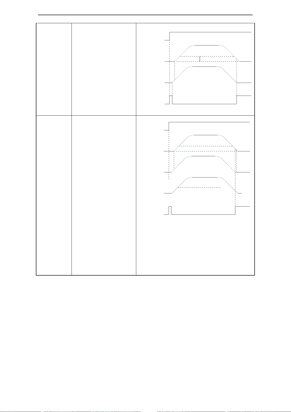
69
1
Output COIN signal when
the difference below P5-00
after the command end
2
output COIN signal
when the command end
and motor speed below
P5-03(rotation detection
speed), pulse difference
below P5-00
/S-ON
|U-08|
|ΔU-12|
Pulse difference
1
0
/COIN
Pulse command
1
0
P5-00
/S-ON
|U-08|
|ΔU-12|
Pulse difference
1
0
|U-00|
Pulse command
/COIN
1
0
Actual speed

70
3
Output COIN signal when
command end, pulse
difference absolute value
below P5-00. If COIN
signal hold the time of
P5-02, output COIN-HOLD
signal
Parameter
Signal
Default
Suitable
mode
Meaning
Modify
P5-46
/NEAR
n.0000
6
Servo motor near
the position
complete signal
Range: 0000-0013, distribute to output
terminal via P5-46. When it set to 0001,
it means output from SO1.
Note: /NEAR can be output from terminal by setting P5-46, please see chapter 5-12-3.
P5-06
Width of positioning near signal
Unit
Default
Range
Suitable mode
Modify
Effective
1 command
unit
50
0~65535
6
Servo OFF
Immediately
Function: when the pulse difference signal is lower than P5-06, output /NEAR signal.
Set the parameter wider than positioning complete signal. Monitor the pulse difference value via U-08.
P5-00
P5-03
/S-ON
|U-08|
|ΔU-12|
Pulse difference
1
0
/COIN
Pulse command
1
0 0 1
/COIN-HOLD
P5-00
P5-02
P5-02
P5-06
P5-00
1 0 1
0
/COIN
/NEAR
U-08
Pulse difference
5-3-7. Positioning near (/NEAR)
Positioning near signal means the servo motor is near the positioning complete. It prompts the device to
prepare the next operation.

71
5-3-8. Command pulse prohibition (/INHIBIT)
P0-23
Pulse difference limit
Unit
Default value
Range
Suitable
mode
Change
Effective
256
commands
50000
0~65535
6
Any
At once
Basic parameters
Parameter
Name
Reference
P0-01
Select the control mode
5-4-1
P3-00
V-REF distribution
5-4-2
P3-01
Rated speed of the corresponding analog voltage
P3-02
Analog voltage speed filter
P3-03
Speed command input dead zone voltage
P3-14
Forward direction max speed command limit
P3-15
Reverse direction max speed command limit
P5-20
Servo ON signal /S-ON
5-2-1
Other parameters
Key words
Parameter
Name
Reference
Zero drift
F1-03
Analog voltage speed command offset
5-4-3
Parameter
Signal
Default
Suitable
mode
Modify
Effective
Modify
P5-32
/INHIBIT
n.0000
6
Any
At once
Range: 0000-0015. When it
set to 0001, it means input
from SO1.
Note: /INHIBIT can be input from input terminal by setting P5-32. Please refer to chapter 5-12-1
(alarm E-100)
Normal
control
(alarm E-100)
Pulse
difference
0 P0-23
To stop the commnad pulse input in position control mode. When /INHIBIT signal is ON, the
command pulse stop counting.
Input signal setting:
5-3-9. Positoin pulse difference
When the pulse difference over the limit value in position control mode, servo will alarm. This limit
value is pulse difference limit.
When the P0-23=0, it will now detect the pulse difference value.
5-4 . Speed control (analog voltage command) (Only for
DS3-PQA)

72
adjustment
auto-adjustment
Proportion
action
P5-21
/P-CON
5-4-4
Zero clamp
P5-31
Zero clamp /ZCLAMP
5-4-5
P3-12
Zero clamp mode
P3-13
Zero clamp speed
Speed
coincidence
checking
P5-39
/V-CMP speed coincidence checking
5-4-6
P5-04
Coincidence speed signal checking
width/V-CMP
Torque limit
P3-28
Forward torque limit
5-4-7
P3-29
Reverse torque limit
P3-23
T-REF distribution
P3-30
Forward external torque limit
P3-31
Reverse external torque limit
P5-25
Forward external torque limit /P-CL
P5-26
Reverse external torque limit /N-CL
P5-42
Output when torque reaches limit value
/CLT
Soft start
P3-09
Soft start acceleration time
5-4-8
P3-10
Soft start deceleration time
Filter
P1-22
Speed command filter mode
5-4-9
P1-23
Speed command filter time constant
Speed reach
detection
P5-51
Speed reach output /V-RDY
5-4-10
P5-05
Reach detection speed
Alarm speed
P3-21
Forward alarm speed
5-4-11
P3-22
Reverse alarm speed
/SPD-D
direction
selection
P5-17
Change the direction
5-5-3
Parameter
Set value
Meaning
Modify
Effective
P0-01
4
Analog voltage command speed control
Servo OFF
Immediately
Function: control the speed by the signal (analog voltage command) input from V-REF terminal
Note:direction switching: positive or negative voltage, SPD-D (P5-27).
P3-00
Name
Set
Meaning
Suitable
mode
Change
Effective
V-REF function
distribution
0
V-REF input as
speed command
4
Servo OFF
At once
P3-01
Analog value of rated speed
Unit
Default setting
Range
Suitabl
e mode
Change
Effective
0.01V
10000
150~30000
1, 2, 4
Servo
OFF
At once
Function: the speed command voltage (V-REF) to run the servo motor at rated speed.
Such as: P3-01=5000 means the motor run at rated speed when analog input voltage = 5.00V
P3-01=8000 means the motor run at rated speed when analog input voltage = 8.00V.
Note: (1) Analog voltage command used for speed limit input without polarity. Whether it is positive
voltage or negative voltage all take absolute value. This absolute value is fit for forward and reverse
direction.
(2) the max allowable voltage of analog input signal is ±10V, please do not use the motor over ±10V.
P3-02
analog voltage speed filter
5-4-1. Control mode selection
5-4-2. Analog value of rated speed

73
Parameter
Signal
Type
Default
State
Meaning
Modify
Effective
P5-21
/P-CON
Input
n.0000
Effective
Run in P control
mode
Any
Re-power
on
Ineffective
Run in PI control
mode
1. /P-CON is the speed control mode signal selected from PI (proportion integral) and P (proportion).
2. If set to P control mode, the motor rotate and micro-vibration caused by speed command input drift
can be decreased. But the servo stiffness will decrease.
3. /P-CON signal can be distributed to input terminal via parameter P5-21. Refer to chapter 5-12-1.
Unit
Default setting
Range
Suitable
mode
Change
Effective
0.01ms
0
0~10000
1, 2, 4
Any
At once
Analog command wiring diagram please refer to chapter 3-2-3
P3-04
Analog speed direction
switching
0
0~1
1, 2, 4
Any
At once
P3-14
Forward max speed command limit
Unit
Default setting
Range
Suitable
mode
Change
Effective
1rpm
Motor rated
0~10000
All the
modes
Servo OFF
At once
P3-15
Reverse max speed command limit
Unit
Default setting
Range
Suitable
mode
Change
Effective
1rpm
Motor rated
0~10000
All the
modes
Servo OFF
At once
Note: P3-14 and P3-15 are effective in all the modes.
Speed command limit
5-4-3. Speed command difference auto-adjustment (F1-03)
When the servo is in analog voltage speed mode, even if the command voltage is 0V, motor will run at
very low speed. The micro-motion will happen when the command voltage micro-offset (mV) of host
controller or external circuit occurs. Auto-adjust the command offset by operate panel of servo.
Take away the analog signal from servo CN1 port in servo bb state (not enabled), then do the following
steps:
Press STATUS/ESC to exit this function.
Note:
1. The present analog voltage is 0V, please follow the above steps to calibrate, so 0V is 0rpm,
motor will reverse run below 0V, motor will forward run above 0V. If the present analog
voltage is 5V, and follow the above steps to calibrate, so 5V is 0rpm, motor will reverse run
below 5V, motor will forward run above 5V.
2. If there is still micro-motion after calibrating, please increase P3-03(set to 5 means the dead
area voltage is 0.005V) or use zero-clamp.
5-4-4. Proportion action command (/P-CON)

74
5-4-5. Zero clamp (/ZCLAMP)
P3-12
Zero clamp mode
Default
setting
Range
Suitable
mode
Meaning
Change
Effective
0
0~2
3, 4, 7
Set zero clamp mode
Servo
OFF
At once
P3-12 setting
Contents
0
ZCLAMP input signal is ON, forced speed command is 0, when the speed below
P3-13, switch to position mode and the servo lock in this position.
1
ZCLAMP input signal is ON, forced set the speed command to 0.
2
ZCLAMP input signal is ON, the speed below P3-13, switch to position mode and the
servo lock in the position.
Note: after entering zero clamp mode, present setting speed is higher than P3-13,
motor doesn’t run, the ZCLAMP signal must be OFF, then motor will run again.
3
ZCLAMP signal is ON, the setting speed is less than P3-13, switch to position control
mode, and servo is locked at this position. At this time, if setting speed is over P3-13,
the motor will run again.
Parameter
Signal
Default
Meaning
Suitable mode
Modify
Effective
P5-39
/V-CMP
n.0000
Speed coincidence
checking signal
3, 4, 7
Any
At once
Range: 0000-0013. Distribute to output terminal through P5-39. When it set to 0002, it means output
from SO2.
Parameter
Signal
Suitable
mode
Default
Meaning
Modify
Effective
P5-31
/Z-CLAMP
3, 4, 7
n.0000
Zero
clamp
Any
At once
Note: /Z-CLAMP signal is distributed to input terminal by parameter P5-31, refer to chapter 5-12-1.
Range: 0000-0014.
P3-13
Zero clamp speed
Unit
Default
setting
Range
Suitable
mode
Change
Effective
rpm
10
0~10000
3, 4, 7
Any
At once
(1) Function
This function is used when host controller uses speed command input and the servo system isn’t
configured the position loop. In other words, the function will be used when the motor must stop and
enter lock state even the V-REF input voltage is not zero.
When set ON the zero clamp function, it will configure the position loop inside the servo, the motor
will do zero clamp within ±1 pulse at this position. The motor will return to zero clamp position even it
is run by external force.
The present speed must be smaller than zero clamp speed when using zero clamp function, it can clamp
the motor shaft from moving. The motor will switch from speed mode to position mode when starting
the zero clamp function. At this time, rotate the motor shaft, it will return to the original position. It will
not return to original position in speed mode, because it has no position feedback.
(2) Input signal setting
(3) Parameter setting
5-4-6. Speed coincidence checking (/V-CMP)
When motor speed is equal to the command speed, servo outputs speed coincidence signal (V-CMP).

75
P3-28
Internal Forward torque limit
Unit
Default
Range
Suitable mode
Modify
Effective
1%
300
0~300
All modes
Servo OFF
Immediately
P3-29
Internal Reverse torque limit
Unit
Default
Range
Suitable mode
Modify
Effective
1%
300
0~300
All modes
Servo OFF
Immediately
1. This parameter is always effective, if this parameter value is less than external torque limit value, the
final limit value is this parameter.
2. The unit is percent of the motor rated torque; the default value is 300%. The real output torque is
different for each type.
P3-30
Forward external torque limit
Unit
Default
Range
Suitable mode
Modify
Effective
1%
300
0~300
2, 3, 4, 5, 6, 7
Any
Immediately
P3-31
Reverse external limit
Unit
Default
Range
Suitable mode
Modify
Effective
1%
300
0~300
2, 3, 4, 5, 6, 7
Any
Immediately
The unit is the percent of motor rated torque; the default value is 300%.
Parameter
Signal
Type
Default
Meaning
Modify
P5-25
/P-CL
Input
n.0000
The necessary condition to use
forward external torque limit
Range: 0000-0015.
P5-26
/N-CL
Input
n.0000
The necessary condition to use
reverse external torque limit
Range: 0000-0015.
Notes: these parameres are the necessary conditions for using forward or reverse external torque limit.
/P-CL, /N-CL can be distributed to input terminal by parameter P5-25, P5-26. Refer to chapter
5-12-1.
Parameter
Function
Set
value
Suitable
mode
Meaning
Modify
Effective
P3-23
Distribute
function to T-REF
0
1, 3, 4, 6,
7
Make T-REF as
external torque limit
input
Servo
OFF
At once
1. For analog voltage command input of torque limit. Get the absolute value of the voltage, the torque
limit value based on the absolute value is suitable for forward and reverse direction.
2. When it is used as torque limit, the value is related to voltage command and P3-24. For example,
P3-24=1000, T-REF voltage command is 5.0V, the torque limit value is 50% of rated torque.
P5-04
Speed coincidence signal width
Unit
Default
Range
Suitable mode
Modify
Effective
rpm
50
0~10000
3, 4, 7
Servo OFF
Immediately
If the difference between motor speed and command speed is less than the value of P5-04, servo
outputs /V-CMP signal.
There is default 10rpm hysteresis loop, please refer to chapter 5-11-4 for hysteresis loop.
5-4-7. Torque limit
1. Internal torque limit (output torque max value limit)
The function is to limit the max output torque by parameters.
2. External torque limit (via input signal)
This function is used in machine motion or timing torque limit. For example: press stop action or robot
workpiece protection.
The torque limit value will be effective when the input signal is ON.
3. External torque limit (via analog voltage command)
This function control the torque via analog voltage. T-REF terminal is used as analog voltage command
terminal. Please note in external analog torque control mode, this function cannot be used.

76
Parameter
Signal
Type
Default
Meaning
Modify
Effective
Suitable
mode
P5-42
/CLT
Output
n.0000
Output signal when
motor output torque
up to P5-28, P5-29.
Any
At once
3, 4, 6, 7
Note: Range: 0000-0013. /CLT signal can be distributed to output terminal by parameter P5-42. When
it is set to 0001, the signal will output from SO1 terminal. Refer to chapter 5-12-3.
P3-09
Soft start acceleration time
Unit
Default
Range
Suitable mode
Modify
Effective
1ms
0
0~65535
3, 4, 7
Any
Servo OFF
P3-10
Soft start deceleration time
Unit
Default
Range
Suitable mode
Modify
Effective
1ms
0
0~65535
3, 4, 7
Any
Servo OFF
1. Enable to do smooth speed control when input step speed command or choose internal speed. Other
cases please set to 0.
2. accerlation/deceleration time is from stop state to rated speed but not from current speed to target
speed.
P3-09: the time from stop state to rated speed.
P3-10: the time from rated speed to stop state.
TREF
distribution
P-CL/N-CL status
Final forward torque
Final reverse torque
0
0
P3-28 decide
P3-29 decide
1
The smaller one of internal
forward torque limit and
external forward torque limit
The smaller one of internal
reverse torque limit and
external reverse torque limit
1
No effect
The smaller one of internal
forward torque limit and
external analog torque
The smaller one of internal
reverse torque limit and
external analog torque
3
0
P3-28 decide
P3-29 decide
1
The smaller one of internal
forward torque limit and
external analog torque
The smaller one of internal
reverse torque limit and
external analog torque
4. Relationship of the parameters
The following are the relationship of internal torque limit, external torque limit, P-CL, /N-CL and
T-REF.
5. Output torque up to limit value signal
The signal means the motor output torque reaches limit value.
5-4-8. Soft start

77
P1-22
Speed command filter mode
Default
setting
Range
Suitable
mode
Meaning
Change
Effective
0
0, 1
3, 4, 7
Filter certain frequency
command pulse
Any
At once
P1-22 setting
Contents
0
First order low pass filter
1
Smoothing filter
P5-51
Name
Default
setting
Meaning
Suitable mode
Modify
Effective
/V-RDY
n.0000
Speed reaching signal
3, 4, 7
Any
At once
Range: 0000-0013, distribute to the output terminal via P5-29. When P5-29=0002, it means output
from SO2 terminal.
P1-23
Speed command filter time
Unit
Default
setting
Range
Suitable
mode
Change
Effective
0.1ms
0
0~65535
3, 4, 7
Any
At once
P5-05
Reach detection speed
Unit
Default
setting
Range
Suitable mode
Change
Effective
rpm
1000
0~10000
3, 4, 7
Servo
OFF
At once
If the motor speed absolute value is larger than P5-05, output the signal /V-RDY.
P3-10: set the time
P3-09: set the time
Speed command
Internal speed
command
Soft start
Rated speed
Rated speed
5-4-9. Filter
Filter time setting:
5-4-10. Speed reach signal (/V-RDY)
Output speed reach signal V-RDY when the motor speed is equal to reach speed.
the output terminal only can have one function at the same time. Please refer to chapter 5-12-3.

78
there is default hysteresis loop 10rpm, please refer to chapter 5-11-4.
Basic parameter
Parameter
Name
Reference
P0-01
Control mode selection
5--1
P5-20
Servo ON signal /S-ON
5-2-1
P3-05
Internal speed 1
5-5-2
P3-06
Internal speed 2
P3-07
Internal speed 3
P5-27
/5SPD-D internal speed direction selection
5-5-3
P5-28
/SPD-A internal speed direction selection
P5-29
/SPD-B internal speed direction selection
Other parameters
Key word
Parameter
Name
Reference
Proportion
action
P5-21
Proportion action command /P-CON
5-4-4
Zero clamp
P5-31
Zero clamp /ZCLAMP
5-4-5
P3-12
Zero clamp mode
P3-21
Forward alarm speed
Unit
Default setting
Range
Suitable
mode
Change
Effective
1rpm
120% of rated
speed
0~10000
All
Servo
OFF
At once
P3-22
Reverse alarm speed
Unit
Default setting
Range
Suitable
mode
Change
Effective
1rpm
120% of rated
speed
0~10000
All
Servo
OFF
At once
Note: 1. the parameters P3-21 and P3-22 are effective in all the modes.
2. the default value is 120% of rated speed. for example: rated speed is 1500, max speed is 1800; rated
speed is 3000, max speed is 3600.
3. these parameters are related to E-080. When the motor is out of control or the speed keeps rising
caused by external force and over the alarm speed, servo will show E-080 alarm.
P3-03
Speed command input dead area voltage
Unit
Default
setting
Range
Suitable
mode
Modify
Effective
0.001V
0
0~500
1, 2, 4
Any
At once
Note:
(1) When the input speed command voltage is in the range of this parameter, the input command
is seemed to be 0.
(2) If there is fretting after calibrating the deviation, please increase the dead area voltage.
5-4-11. Alarm speed
5-4-12. Speed command input dead area voltage
5-5.Speed control (internal speed)

79
P3-13
Zero clamp speed
Speed
coincidence
checking
P5-39
/V-CMP speed coincidence checking
5-4-6
P5-04
speed coincidence checking signal width
/V-CMP
Torque limit
P3-28
Internal forward torque limit
5-4-7
P3-29
Internal reverse torque limit
P3-23
T-REF distribution
P3-30
Forward external torque limit
P3-31
Reverse external torque limit
P5-25
Forward external torque limit /P-CL
P5-26
Reverse external torque limit /N-CL
P5-42
Torque up to limit value output /CLT
Soft start
P3-09
soft start acceleration time
5-4-8
P3-10
soft start deceleration time
Filter
P1-22
Position command filter mode
5-4-9
P1-23
Speed command filter time
Speed reach
detection
P5-51
Speed reach output /V-RDY
5-4-11
P5-05
Reach detection speed
P3-05
Internal speed 1
Unit
Default
Range
Suitable mode
Modify
Effective
1rpm
0
-9999~+9999
3
Any
Immediately
P3-06
Internal speed 2
Unit
Default
Range
Suitable mode
Modify
Effective
1rpm
0
-9999~+9999
3
Any
Immediately
P3-07
Internal speed 3
Unit
Default
Range
Suitable mode
Modify
Effective
1rpm
0
-9999~+9999
3
Any
Immediately
Parameter
Set value
Meaning
Modify
Effective
P0-01
3
Speed control: internal speed selection
Servo OFF
Immediately
Function: internal speed selection will set 3 motor speeds and select the speed by external signal. It is no
need to configure external speed generator or pulse generator.
M
Servo motor
Run the motor
at set speed
Servo unit
Speed selection
SPEED1 P3-05
SPEED2 P3-06
SPEED3 P3-07
User parameter
/SPD-D
/SPD-A
/SPD-B
Input
No need external speed or
pulse generator
5-5-1. Control mode selection
5-5-2. Internal speed setting
5-5-3. Input signal setting
Switch the running speed by below input signal:

80
Parameter
Signal
Default
Suitable
mode
Modify
Modify
Effective
P5-27
/SPD-D
n.0000
1, 2, 3, 4
Range: 0000-0015.
Distribute to input terminal
through P5-27.
Any
At once
P5-28
/SPD-A
n.0000
3, 6
Range: 0000-0015.
Distribute to input terminal
through P5-28.
P5-29
/SPD-B
n.0000
3, 6
Range: 0000-0015.
Distribute to input terminal
through P5-29.
Input signal
Direction
Running speed
/SPD-D
SPD-A
SPD-B
0
0
0
Forward
Internal speed is zero
0
1
P3-05: SPEED1
1
1
P3-06: SPEED2
1
0
P3-07: SPEED3
1
0
0
Reverse
Internal speed is zero
0
1
P3-05: SPEED1
1
1
P3-06: SPEED2
1
0
P3-07: SPEED3
0
+SPEED1
Stop
+SPEED2
+SPEED3
-SPEED1
-SPEED2
-SPEED3
Speed 1
Speed 2
Speed 3
stop
Speed 1
Speed 2
Speed 3
Stop
Speed up down is decided by
P3-09, P3-10
SPD-A
SPD-B
SPD-D
OFF
OFF
OFF
OFF
OFF
OFF
OFF
OFF
OFF
OFF
OFF
OFF
OFF
OFF
ON
ON
ON
ON
ON
ON
ON
ON
ON
ON
ON
ON
ON
(1) Function realization
(2) Running example

81
5-6.Speed control (pulse frequency command)
Basic parameter
Parameter
Name
Reference
P0-01
Control mode selection
5-6-1
P5-20
Servo ON signal /S-ON
5-2-1
P0-10
Pulse command form
5-3-2
P0-15
Command pulse frequency at rated speed
5-6-3
P0-16
Speed command pulse filter time
5-6-4
Other parameters
Key word
Parameter
Name
Reference
Proportion
action
P5-21
Proportion action command /P-CON
5-4-4
Zero clamp
P5-31
Zero clamp /ZCLAMP
5-4-5
P3-12
Zero clamp mode
P3-13
Zero clamp speed
Speed
coincidence
checking
P5-39
/V-CMP speed coincidence checking
5-4-6
P5-04
speed coincidence checking signal width
/V-CMP
Torque limit
P3-28
Internal forward torque limit
5-4-7
P3-29
Internal reverse torque limit
P3-23
T-REF distribution
P3-30
Forward external torque limit
P3-31
Reverse external torque limit
P5-25
Forward external torque limit /P-CL
P5-26
Reverse external torque limit /N-CL
P5-42
Torque up to limit value output /CLT
Speed reach
detection
P5-51
Speed reach output /V-RDY
5-4-11
P5-05
Reach detection speed
P0-15
command pulse frequency at rated speed
Unit
Default
Range
Suitable mode
Modify
Effective
100Hz
1000
1~10000
7
Servo OFF
Immediately
Note: the unit is 100Hz.
Example: P0-15=300, command pulse frequency at rated speed=30kHz;
P0-15=1000, command pulse frequency at rated speed= 100kHz.
Parameter
Set value
Meaning
Modify
Effective
P0-01
7
Speed control: pulse frequency speed
command
Servo OFF
Immediately
Function: speed command is decided by external pulse frequency, but not related to pulse quantity.
The wiring is the same as position command. Select CW, CCW mode or direction + pulse mode, AB
phase pulse mode.
5-6-1. Control mode selection
5-6-2. Pulse frequency command
Pulse frequency command is the same as external pulse command position control (mode 6), refer to
chapter 5-3-2.
5-6-3. Command pulse frequency at rated speed

82
5-6-4. Speed command pulse filter time
P0-16
speed command pulse filter time
Unit
Default
Range
Suitable mode
Modify
Effective
0.01ms
100
0~10000
7
Any
Immediately
When the command pulse frequency is low, setting a suitable value for this parameter can decrease the
speed fluctuation.
Parameter
Name
Reference
P0-01
Control mode selection
5-7-1
P3-23
T-REF distribution
P3-24
The analog voltage of rated torque
5-7-2
P3-25
Analog voltage torque command filter
P3-26
Torque command input dead zone voltage
P5-20
Servo ON signal /S-ON
5-2-1
Other parameters
Key words
Parameter
Name
Reference
Zero drift
adjustment
F1-04
Torque command offset auto-adjustment
5-7-3
Filter
P3-25
Torque command filter time
5-7-4
Speed limit
P3-00
V-REF distribution
5-7-5
P3-16
Internal forward speed limit for torque control
P3-17
Internal reverse speed limit for torque control
P5-43
Speed reach limit output /VLT
/SPD-D
direction
selection
P5-27
Speed direction changing
5-5-3
parameter
Name
Default
setting
Suitable
mode
Meaning
Change
Effective
P3-23
T-REF
distribution
0
All
T-REF input as speed
command
Servo
OFF
At once
P3-24
Analog value of rated torque
Unit
Default setting
Range
Suitable
mode
Change
Effective
Parameter
Parameter
Set
Function
Modify
Effective
P0-01
2
Torque control: analog voltage command
Servo OFF
Immediately
Function: Control the torque by the analog voltage signal input from T-REF terminal.
Direction switching: negative or positive voltage or SPD-D (P5-27).
5-7.Torque control (analog voltage command) (only for
DS3-PQA)
5-7-1. Control mode selection
5-7-2. The analog value of rated torque

83
0.001V
10000
1500~30000
All
Servo
OFF
At once
Function: set the speed command voltage (T-REF) to run the servo motor at rated speed
Example: P3-24=5000, motor run at rated torque when analog input voltage is 5.00V
P3-24=8000, motor run at rated torque when analog input voltage is 8.00V
Note: analog voltage command input for torque limit has no polarity. Get the absolute value whatever it
is positive or negative voltage. The torque limit value based on this absolute value is fir for forward and
reverse direction.
Analog input signal max allowable voltage is ±10V, do not give the signal out of this range.
P3-25
Analog voltage torque command filter
Unit
Default setting
Range
Suitable
mode
Change
Effective
0.01ms
0
0~10000
All
Servo
OFF
At once
The analog torque command input please refer to chapter 3-2-4
P3-26
Torque command input dead zone voltage
Unit
Default
setting
Range
Suitable
mode
Change
Effective
0.001V
0
0~500
2
Any
At once
Note: when the input torque command voltage is smaller than this parameter, it considers the input
torque command is 0.
If there is fretting after calibrating the deviation, please increase the dead area voltage.
P3-25
torque command filter time
Unit
Default
Range
Suitable mode
Modify
Effective
0.01ms
0
0~10000
All
Any
Immediately
1-time delay filter will smooth the torque command. If set the value too large, the reponse will be
decreased.
5-7-3. Torque command offset autoadjustment (F1-04)
The motor will run at microspeed even the command voltage is 0V in analog voltage torque mode. This
situation will happen when host controller or the command voltage of external circuit has micro-offset
(mV). Use the operate panel to auto-adjust the offset.
Take away the analog signal from servo CN1 port in servo bb state (not enabled), do the following
steps:
Press STATUS/ESC to exit this function.
Note:
(1) Present analog voltage is 0V, follow the above steps to calibrate, 0V is 0% of output torque,
the motor reverse output the torque below 0V, motor forward output the torque above 0V. if
the present analog voltage is 5V, follow the above steps to calibrate, 5V is 0% of output torque,
the motor reverse output the torque below 5V, motor forward output the torque above 5V.
(2) If there is still fretting after calibrating, increase P3-26, if set to 5, the dead area voltage is
0.005V.
5-7-4. Torque command filter time
5-7-5. Torque limit
5-7-5-1. Internal speed limit
Limit the speed of torque control by setting below parameters:

84
Parameter
Function
Set value
Meaning
Modify
Effective
P3-00
V-REF function
distribution
1
Make V-REF as external
speed limit input, actual
speed limit depends on
external analog speed limit
Servo OFF
Immediately
1. The analog voltage has no polarity. The absolute value of the voltage is suitable for forward and
reverse direction.
2. The parameter value is related to voltage command and P3-01 when it is used as speed limit value.
For example: P3-01=5000 (voltage of rated speed is 5.0V), V-REF voltage command is 1.0V, the
speed limit is 20% of rated speed.
Parameter
Signal
Default
Meaning
Modify
Suitable mode
Effective
P5-43
/VLT
n.0000
Speed limit
checking
Any
1, 2, 6
At once
Range: 0000-0013. Distribute to output terminal through P5-43. When it set to 0001, it means
output from SO1.
Basic parameter
Parameter
Name
Reference
P0-01
Control mode selection
5-8-1
P5-20
Servo ON signal /S-ON
5-2-1
P3-33
Internal torque command
5-8-2
Other parameters
Key words
Parameter
Name
Reference
Filter
P3-25
Torque command filter time
5-7-4
Speed limit
P3-16
Internal forward speed limit of torque control
5-7-5
P3-17
Internal reverse speed limit of torque control
P3-14
Forward max speed limit
P3-15
Reverse max speed limit
P3-00
V-REF function distribution
P5-43
Speed up to limit value output
/SPD-D
direction
selection
P5-27
Speed direction change
5-5-3
P3-16
internal forward speed limit in torque control mode
Unit
Default
Range
Suitable mode
Modify
Effective
1rpm
Motor
rated
0~10000
1, 2
Any
Immediately
Note: the actual speed is max speed even this parameter speed is larger than the max speed.
P3-17
internal reverse speed limit in torque control mode
Unit
Default
Range
Suitable mode
Modify
Effective
1rpm
Motor
rated
0~10000
1, 2
Any
Immediately
Note: the actual speed is max speed even this parameter speed is larger than the max speed.
5-7-5-2. External speed limit
Limit the speed output of torque control mode by the analog voltage command input from V-REF
terminal.
5-7-5-3. Speed up to limit value output
5-8.Torque control (internal setting)

85
5-8-1. Control mode selection
Fieldbus parameters
parameter
Function
Range
Set
value
Default
value
Modify
Effective
P0-01
Control mode
1: torque (command)
2: torque (analog)
3: speed (terminal command)
4: speed (analog)
5: position (internal) - cannot
support
6: position (pulse)
7: speed (pulse)
10: fieldbus position mode
10 6 Servo
OFF
at once
P0-03
Enable mode
1: IO enable
2: software enable
3: fieldbus enable
3 1 Servo
OFF
At once
P7-00
RS485 station
no.
1~20
1 Servo
OFF
At once
P7-01
RS485 serial
port
parameters
n.xx□□
Baud rate
06:19200
07:38400
08:57600
09:115200
0A:192000
0B:256000
0C:288000
0D:384000
0E:512000
0F:576000
10:768000
11:1M
12:2M
13:3M
2213
2206
Servo
OFF
At once
Parameter
Set value
Function
Modify
Effective
P0-01 1 Torque control: internal setting
Servo OFF
Immediately
Function: Control the torque by internal torque command.
P3-33
Internal torque command
Unit
Default
Range
Suitable mode
Modify
Effective
1% rated torque
0
-300~+300
1
Any
Immediately
The unit of this parameter is 1% of the rated torque.
For example: P3-33=50, motor forward run with 50% of the rated torque;
P3-33= -20, motor reverse run with 20% of the rated torque.
5-8-2. Internal torque command
5-9.Motion fieldbus control (position mode) (only for DS3E)
Motion control is the real-time management for mechanical part position and speed, make the
movement according to the expected motion track and parameters.
XDC series PLC use fieldbus motion control mode to replace the pulse outputting mode. It is
bus communication mode, baud rate is 3M, the system speed is fasster, the wiring is simple
and sharing.
Use XINJE industry filedbus communication protocol, support XINJE filedbus products.

86
14:4M
15:5M
16:6M
n.x□xx
Stop bit:
0: 2 bits 2: 1 bit
n.□xxx
Parity bit
0: no parity 1: odd
parity 2: even
parity
P7-02
RS485
communication
protocol
1:Modbus
2:XNet
2 2
P7-05
Slave station
quantity
10
P7-06
Repeat times
3
Monitoring parameters
parameter
Explanation
Mark
U0-61
Communication error times
U0-62
Synchronization frame receive error times
(overtime or data error)
U0-64
Data frame receive error times (overtime
or data error)
U0-66
CRC error times
U0-67
UART error times
UART module error reasons:
1. RS485 noise is too large
2. CPU hasn’t read offset register data in
time caused the data damaged.
U0-68
Communication overtime times
If the servo continuous communication error
period ≥P7-06, U0-68 +1, servo XNet state
switches to “initial state”, the priority of
UART decreases, wait the synchronization
frame, servo will not alarm right now.
Basic parameters
Parameter
Name
Use
U0-57
Absolute encoder present
position feedback
Read double word address 0x1039(hex), it is present
encoder position, with negative and positive pulses.
U0-58
F1-06
Absolute encoder clear circles
Write 1 in address 0x2106(hex) can clear the
circles(effective when servo is in bb state, write 0 in
0x2106 after clearing)
Servo drive model
Servo motor model
Cable
Encoder
DS3-20P1-PNA
MS-40ST-T00330B-20P1
Encoder cable CP-DP-B-02
(02 is length)
Power cable CM-P07-02
20-bit absolute
encoder
DS3-20P2-PNA
MS-60ST-T00630B-20P2
MS-60ST-T00630BZ-20P2
DS3-20P4-PNA
MS-60ST-T01330B-20P4
MS-60ST-T01330BZ-20P4
DS3-20P7-PNA
MS-80ST-T02430B-20P7
MS-80ST-T02430BZ-20P7
DS3-21P5-PTA
MS-130ST-T10015B-21P5
Encoder cable CP-DL-B-02
17-bit absolute
5-10. Absolute encoder servo drive
Absolute encoder servo no need origin reset after power on again.
Servo drive model: DS3-口口 P 口-PTA/PNA
Servo motor model: MS-口口 ST-T 口口口口口 B/BZ-口口 P 口

87
MS-130ST-T10015BZ-21P5
MS-130ST-T06025B-21P5
MS-130ST-T06025BZ-21P5
Power cable CM-L15-02
encoder
5
4 blue (SD+)
3 blue/black(SD-)
2
1 shield
10
9 green(battery+)
8 red(5V)
7 green/black(battery-)
6 black (0V)
15
14
13
12
11
5 shield
4 blue (SD+)
3 blue/black(SD-)
2
1
10
9 green(battery+)
8 red(5V)
7 green/black(battery-)
6 black(0V)
15
14
13
12
11
5 shield
4 blue(SD+)
3 blue/black(SD-)
2
1
10
9 green(battery+)
8 red(5V)
7 green/black(battery-)
6 black(0V)
15
14
13
12
11
5 shield
4 blue(SD+)
3 blue/black(SD-)
2
1
10
9 green(battery+)
8 red(5V)
7 green/black(battery-)
6 black(0V)
15
14
13
12
11
CN1 (DB9 male port): the
pin definition at drive side
Pin
Name
CN1-2
A
CN1-3
B
Parameter
Function
Default setting
Setting range
Effective time
P7-00
Modbus station no.
1
0~255
Servo OFF
1
5
9
6
5-10-1. Absolute enocder servo encoder cable
15-core aviation plug—encoder cable
DB9 female port related to the 15-core aviation plug
15-core AMP plug –encoder cable
DB9 female port related to 15-core AMP plug
5-10-2. Read the absolute encoder servo position
The encoder position information is transferred through RS485 port according to Modbus-RTU
protocol.
17-bit absolute encoder, the pulse per circle is 131072.
U0-57(Modbus address is H1039), double word, encoder present position.
RS-485 communication
Communication parameter explanation:
RS485 port default communication parameters: baud rate 19200bps, data bit 8, stop bit 1, even
parity, modbus station no. 1.
Modbus station number can be set through P7-00:
P7-00 is RS485 port modbus station no.

88
P7-01 communication parameter:
Parameter
Function
Default
setting
Setting range
Effective
time
n.xx□□
Baud rate
06 00~10
00: 300
01: 600
02: 1200
03: 2400
04: 4800
05: 9600
06: 19200
07: 38400
08: 57600
09: 115200
0A: 192000
0B: 256000
0C: 288000
0D: 384000
0E: 512000
0F: 576000
10: 768000
11: 1M
12: 2M
13: 3M
14: 4M
15: 5M
16: 6M
Servo
OFF
n.x□xx
Stop bit
2
0: 2-bit, 2: 1-bit
Servo
OFF
n.□xxx
Parity bit
2
0~2
0: no parity, 1: odd parity, 2: even parity
Servo
OFF
Note: data bit cannot be set, it is 8-bit.
Parameter
Function
Default
setting
Setting range
Effective
time
P7-02
RS485 communication
protocol
1
1: Modbus Rtu protocol
2: Xnet fieldbus protocol
Servo
OFF
P7-02 is RS485 communication protocol:
(1) support standard Modbus-RTU protocol, used as Modbus slave device.
(2) RS232 and RS485 port can be used at the same time.
5-10-3. The use and replacement of battery
When the servo power supply is OFF, the battery can keep the absolute encoder position information.
When the servo power is on again, the upper device can read the motor encoder present position
through Modbus communication.
Battery specification: No.5 battery, 3.6V (ER14505 AA 3.6V).
When the battery voltage is below 2.75V, servo drive will show E-222 alarm (absolute encoder battery
under voltage). The alarm only outputs when the servo is ON.
Note:
(1) Please change the battery every two years.
(2) If the battery is under voltage, when the servo power supply is OFF and ON again, the data in
the absolute encoder will miss. Please protect the program and avoid equipment error action.
(3) Please check the firmware version U2-22/U2-23, for the version after 20160304, P0-79=1
means battery under voltage alarm is invalid, P0-79=0 means battery under voltage alarm is
valid.
The steps to replace the battery:
Please replace the battery when the servo power supply is ON, otherwise the encoder data will be
error. After replacement, please re-power on the servo drive to clear the E-222 alarm.
5-11.Other output signals
5-11-1. /ALM and /ALM-RST
Servo alarm output /ALM
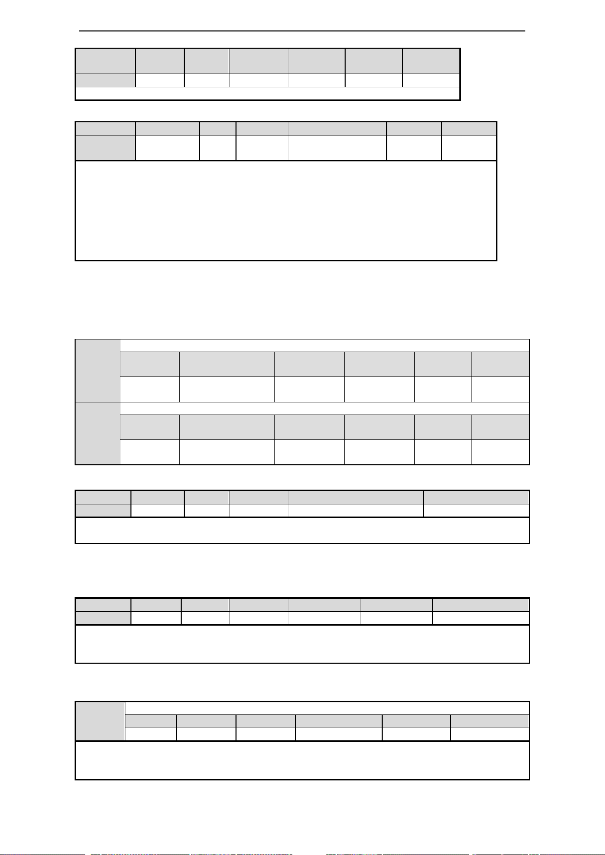
89
Alarm reset /ALM-RST
P3-19
Forward warn speed
Unit
Default setting
Range
Suitable
mode
Change
Effective
1rpm
Related to the
motor
0~10000
All
Servo
OFF
At once
P3-20
Reverse warn speed
Unit
Default setting
Range
Suitable
mode
Change
Effective
1rpm
Related to the
motor
0~10000
All
Servo
OFF
At once
Parameter
Signal
Type
Default
Suitable
mode
Modify
Effective
P5-47
/ALM
Output
n.0002
All
Any
At once
Output always open signal from SO2
Parameter
Signal
Type
Default
Meaning
Modify
Effective
P5-24
/ALM-RST
Input
n.0002
Input always open
signal from SI2
Any
At once
1. Find the alarm reason and fix it, then clear the alarm via this signal.
2. /ALM-RST can be distributed to input terminal via this parameter. As the alarm signal is
related to the safe running of servo, /ALM-RST signal cannot be set to always effective.
(n.0010);
3. The alarm related to encoder such as E-013□ (0, 1, 2), E-014□ (0, 1, 2) cannot be reset via
/ALM-RST.
4. The range is 0000-0015. /ALM-RST can be distributed to input terminal via parameter
P5-24.
Parameter
Signal
Type
Default
Meaning
Range
P5-45
/WARN
Output
n.0000
Warning output
0000-0013
When the warning happens, servo will not be forced OFF but output the warning.
/WARN can be distributed to input terminal via parameter P5-45.
Parameter
Signal
Type
Default
Suitable mode
Modify
Effective
P5-40
/TGON
Output
n.0000
All
Any
At once
1. The servo will be considered in the rotation when the servo motor speed is higher than P5-03.
2. The range is 0000-0013. /TGON can be distributed to output terminal via parameter P5-40, refer to
chapter 5-12-3.
P5-03
Internal torque command setting
Unit
Default
Range
Suitable mode
Modify
Effective
1rpm
50
1~10000
All the modes
Servo OFF
Immediately
Set the range of rotation checking output. If servo motor speed is up to P5-03, the servo motor is
considered to be running and output rotation checking signal (/TGON).
There is default 10rpm hysteresis loop, please refer to chapter 5-11-4.
5-11-2. /WARN
Set the warn output threshold. When the motor speed is larger than the threshold, output /WARN.
5-11-3. Rotation checking (/TGON)
(1) Signal setting
(2) Parameter setting

90
5-11-4. Hysteresis loop
Parameter
Signal
Default
setting
Meaning
Range
Modify
Effective
P5-48
/Z
n.0000
Default not distribute
to terminal
0000~0013
Any
At once
P5-19
Z phase
pulse width
2ms
Z phase pulse width
2~20
Any
At once
1. /Z signal can be distributed to the output terminal through P5-48, refer to chapter 5-12-3.
2. Z phase signal is single pulse output mode, the default pusle width is 2ms, it can set through P5-19, it
is not related to the motor speed.
Parameter
Signal
Default
Meaning
Modify
Effective
P5-41
/S-RDY
n.0003
SO3 and COM pass through
when servo is ready
Any
At once
n.0013
SO3 and COM cut off when
servo is ready
The range is 0000-0013. It can distribute to other output terminal through P5-41. Refer to
chapter 5-12-3.
Encoder Z phase signal
P5-48=n.0011
SO1 output
P5-48=n.0001
SO1 output
2ms
40rpm
/TGON
50rpm
60rpm
rpm
t
Loop width
The hysteresis loop can prevent the system oscillation caused by parameter fluctuating around certain
value. There is hysteresis loop width after setting the hysteresis loop value. It will act when the
parameter is larger than certain value. It will release the action when the parameter is smaller than
another value. The loop width decides the interval time of action. The action is sensitive and frequent
for small loop width. The action is slow for large loop width. Please note that rotation detection speed
(P5-03), same speed detection speed (P5-04), reach detection speed (P5-05) all have 10rpm hysteresis
loop. For example, P5-03 set to 50, rotation detection/TGON output terminal is SO3.
5-11-5. Servo ready (/S-RDY)
It will output /S-RDY signal when servo power on and no alarm.
5-11-6. Encoder Z phase output (/Z) (only for DS3-PQA/DS3-PTA)

91
P0-18
Encoder feedback pulse per circle (low bit)
Unit
Default
setting
Range
Suitable
mode
Change
Effective
1
2500
0~9999
All
Servo OFF
At once
P0-19
Encoder feedback pulse per circle (high bit)
Unit
Default
setting
Range
Suitable mode
Change
Effective
10000
0
0~65535
All
Servo OFF
At once
P0-20
Encoder pulse frequency division (numerator)
Unit
Default
setting
Range
Suitable
mode
Change
Effective
—
1
1~65535
All
Servo OFF
At once
P0-21
Encoder pulse frequency division (denominator)
Unit
Default
setting
Range
Suitable
mode
Change
Effective
—
1
1~65535
All
Servo OFF
At once
Explanation:
1. encoder feedback pulse is decided by P0-18, P0-19. When P0-18=P0-19=0, encoder pulse frequency
division will work. For example, the motor feedback 2500 pulses per circle, P0-18=P0-19=0 P0-20=1,
P0-21=4, the calculation method is (U2-21/22)*P0-20/P0-21.
2. If it is single phase count, the count value is equal to setting value for motor rotating one circle. If it
is AB phase count, the count value is 4 times of setting value for motor rotating one circle.
3. the feedback value should under 10000. If it is larger than 10000, the system will operate as 10000.
P0-17
Pulse frequency division output direction (DS3E/L cannot support)
Unit
Default
setting
Setting range
Suitable
mode
Modification
Effective
—
0
0~1
All
Servo OFF
At once
0: same to count direction 1: reverse to count direction
5-11-7. ABZ phase feedback signal of encoder (CN1 15-pin support)
1. Wiring diagram
DS3-2□P□-PQA/ DS3-4□P□-PQA和 DS3L-2□P□-PQA/ DS3L-4□P□-PQA support differential
output AB phase feedback signal.
Please see the following wiring diagram of DS3-21P5-PQA and Xinje PLC XC3-32RT-E.
Drive CN1(DB15) differential signal to collector PLC
2. Encoder feedback pulses per circle (DS3L cannot support)

92
P5-10
The trigger condition of user-defined output 1
Default trigger
condition
Trigger
condition
setting
Unit
Suitable
mode
Change
effective
0
See below table
Related to
trigger condition
All the
modes
servo
OFF
At once
P5-11
The comparison value for the trigger condition of user-defined output 1
Unit
Default setting
Range
Suitable
mode
Change
Effective
Related to
trigger
condition
0
-9999~9999
All the
modes
Servo
OFF
At once
P5-12
When P5-10≥P5-11 or P5-10<P5-11, SOx output
Setting
value
Function
Default
value
Suitable
mode
Change
Effective
0
P5-10≥P5-11, SOx output
0
All the
modes
Servo
OFF
At once
1
P5-10<P5-11, SOx output
2
P5-10 absolute value ≥P5-11,
SOx output
3
P5-10 absolute value ≤P5-11,
SOx output
P5-13
User-defined output 1 hysteresis loop
Unit
Default
setting
Range
Suitable
mode
Change
Effective
Related to trigger
condition
0
-9999~9999
All the
modes
Servo
OFF
At once
P5-52
Output terminal setting of user-defined output 1
Signal name
Default
setting
Meaning
Change
User-defined
output 1
n.0000
Default setting is
not distribute to
the output terminal
Range 0000-0013, distribute to the
output terminal through P5-52.
P5-14
The trigger condition of user-defined output 2
Default trigger
condition
Trigger
condition
setting
Unit
Suitable mode
Change
Effective
0
See below
table
Related to
trigger
condition
All the modes
Servo
OFF
At once
P5-15
The comparison value for the trigger condition of user-defined output 2
Unit
Default
setting
Range
Suitable mode
Change
Effective
Related to
trigger
condition
0
-9999~9999
All the modes
Servo
OFF
At once
P5-16
When P5-14≥P5-15 or P5-14<P5-15, SOx output
Setting
value
Function
Default
setting
Suitable
mode
Change
Effective
5-11-8. User-defined output signal
User can define 2 outputs. The defined method is SOx output when A>B or A<B. A is 9 activating
conditions, B is user-defined comparison value.
User-defined output 1:
User-defined output 2:

93
please refer to chapter 5-11-4 for hysteresis loop.
Trigger condition (P5-10/P5-14)
Meaning
Unit
DS3 series
DS3E/DS3L
series
0 0 -
—
7203
0203
Current command (torque command)
Rated current %
7205
0205
Current feedback (torque feedback)
Rated current %
7238
0238
Torque feedforward
7301
0301
Speed command
rpm
7302
0302
Speed feedback
rpm
7307
0307
Speed deviation initial value
7308
0308
Speed deviation filter value
rpm
7319
0319
Speed feedforward initial value
7320
0320
Speed feedforward filter value
4402
4402
Position command
1 command
4404
4404
Position feedback
1 command
1406
1406
Position deviation filter value
1 command
7501
0501
Bus voltage initial value
V
7502
0502
Bus voltage filter value
V
7503
0503
Drive internal temperature
℃
0
P5-14≥P5-15, SOx output
0
All the
modes
Servo
OFF
At once
1
P5-14<P5-15, SOx output
2
P5-14 absolute value
≥P5-15, SOx output
3
P5-14 absolute value <
P5-15, SOx output
P5-17
User-defined output 2 hysteresis loop
Unit
Default
setting
Range
Suitable mode
Change
Effective
Related to
trigger
condition
0
0~65535
All the modes
Servo
OFF
At once
P5-53
Output terminal setting of user-defined output 2
Signal name
Default
setting
Meaning
Change
User-defined
output 2
n.0000
Default setting is
not distribute to
the output terminal
Range 0000-0013, distribute to the
output terminal through P5-53
P5-18
I/O filter time
Unit
Default setting
Range
Suitable mode
Change
Effective
ms 0 0~10000
All the modes
Servo OFF
At once
Parameter
Signal
Type
Default
Suitable
mode
Modify
Meaning
Effective
P5-30
/C-SEL
Input
n.0000
All
Any
Switch the mode
At once
Trigger conditions for choice
5-11-9. IO filter time
5-11-10.Switch the control mode
Servo can switch between submode 1 and 2 by external input signal.
(1) Switch signal

94
Signal
State
Control mode
/C-SEL
0
P0-01: submode 1
1
P0-02: submode 2
Parameter
meaning
Set
value
Meaning
Terminal
voltage
Terminal
state
Signal
state
n.00 y x
00: no meaning
y: 0 always open
1 always close
x: input terminal
no.
n.0000
Not distribute to terminal
input
- - 0
n.000x
Input always open signal
from SIx
H
Disconnect
to 0V
0
L
Connect to
0V
1
n.0010
Set the signal to be always
valid
- - 1
n.001x
Input always close signal
from SIx
H
Disconnect
to 0V
1
L
Connect to
0V
0
Note: if the distributed terminal has other signal, set the signal to other terminal or set to unused.
Note: Range: 0000-0015. /C-SEL can be distributed to input terminal via parameter P5-14, refer to
chapter 5-12-1.
Wiring example of input signal
Parameter
Set value
Terminal
state
Signal
state
Meaning
P5-34
n.0001
Disconnect
to 0V
0
Clear the pulse offset at the moment of SI1 and
0V pass through
Connect to
0V
1
n.0011
Disconnect
to 0V
1
Clear the pulse offset at the moment of SI1 and
0V cut off
Connect to
0V
0
Note: the default input of SI1 is /SON, make sure to distribute P5-20(/SON) to other terminal or set to
unused.
CN0-11
CN0-7
SI1
+24V
3.3KΩ
DS3-21P5-PQA: CN0-11 is +24V terminal, CN0-7 is
SI1 terminal. For the example, distribute /CLR signal
to SI1.
(2) Function realization
5-12. I/O signal distribution
5-12-1. Input signal distribution
DS3-2□P□-PQA, DS3-4□P□-PQA
Parameter range: P5-20~P5-36
Example: take the input signal /CLR (P5-24) of DS3-21P5-PQA as an example to explain the terminal
distribution.

95
5-12-2. Default setting of input terminal
Input
Type
SI1
SI2
SI3
SI4
SI5
DS3-2□P□-PQA
DS3-4□P□-PQA
/S-ON
/ALM-RST
/P-OT
/N-OT
Not
distribute
Parameter meaning
Set value
Meaning
Signal
state
Terminal state
n.00 y x
00: pointless
y: 0 always open
1 always close
x: output terminal
no.
n.0000
Not distribute to
terminal input
-
-
n.000x
Output always open
signal from SOx
0
Cut off with COM
1
Pass through with COM
n.0010
Set the signal to be
always valid
-
-
n.001x
output always close
signal from SOx
0
Pass through with COM
1
Cut off with COM
Note: If the distributed terminal has other signal, please set the signal to other terminal or set to unused.
Output terminal wiring example
Parameter
Set
value
/CLT
Terminal state
Meaning
P5-42
n.0001
0
SO1 and COM pass
through
Output limit signal when motor torque
reaches the set value
1
SO1 and COM cut off
Output limit signal when motor torque
reaches the set value
Note: the default output of SO1 is /COIN. Set the P5-38 (/COIN) to other terminal or unused in order to
avoid terminal signal conflict.
Output terminal
SO1
SO2
SO3
Function
/COIN
/ALM
/S-RDY
Basic parameter
parameter
Name
Reference
U0-57
Absolute
encoder present
position
feedback
(0000~9999)*1
Encoder pulse
U0-58
(0000~65535)*10000
COM
SO1
CN0-14
CN0-12
DS3-21P5-PQA: SO1 is CN0-12, COM is CN0-14.
Note: the same input terminal can distribute one function parameter. If more function parameters
distribute to the same terminal, the system will delete the former setting and keep the present setting.
5-12-3. Output terminal distribution
DS3-2□P□-PQA, DS3-4□P□-PQA
Parameter range: P5-37~P5-47, P5-51
Example: take /CLT signal of DS3-21P5-PQA as an example to explain output terminal distribution.
5-12-4. Default setting of output terminal
Note: the same output terminal can distribute one function parameter. If more function parameters
distribute to the same terminal, the system will delete the former setting and keep the present setting.
5-13. DS3-PTA series absolute encoder servo drive
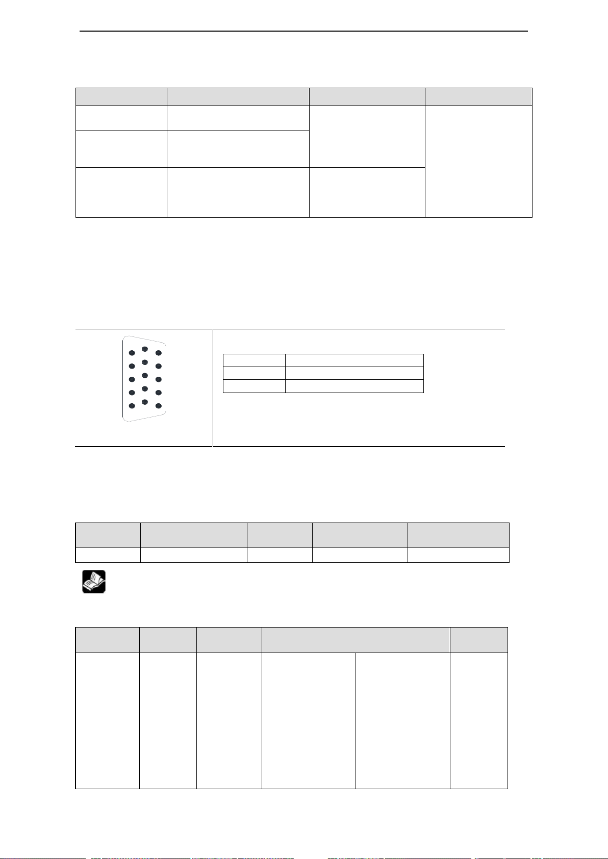
96
Absolute encoder servo no need to reset origin after power on again and run directly.
Drive model
Motor model
Cable
Absolute encoder
DS3-20P4-PTA
MS-60ST-T01330B-20P4
MS-60ST-T01330BZ-20P4
Encoder cable
CP-DP-B-02
(02 is 2meter)
Power supply cable
CM-P07-02
17-bit absolute
encoder
DS3-20P7-PTA
MS-80ST-T02430B-20P7
MS-80ST-T02430BZ-20P7
DS3-21P5-PTA
MS-130ST-T10015B-21P5
MS-130ST-T10015BZ-21P5
MS-130ST-T06025B-21P5
MS-130ST-T06025BZ-21P5
Encoder cable
CP-DL-B-02
Power supply
CM-L15-02
CN1 port: at drive side
Pin no.
Name
CN1-14
A
CN1-15
B
Parameter
Function
Default
setting
Range
Effective
P7-00
Modbus station no.
1
0~255
Servo OFF
parameter
Function
Default
setting
Range
Effective
n.xx□□
Baud rate
06 00~10
00: 300
01: 600
02: 1200
03: 2400
04: 4800
05: 9600
06: 19200
07: 38400
08: 57600
09: 115200
0A: 192000
0B: 256000
0C: 288000
0D: 384000
0E: 512000
0F: 576000
10: 768000
11: 1M
12: 2M
13: 3M
14: 4M
Servo
OFF
1
5
6
10
11
15
Servo drive model: DS3-口口 P 口-PTA
Servo motor model: MS-口口 ST-T 口口口口口 B/BZ-口口 P 口
5-13-1. Read the absolute encoder position
Servo drive transfers the encoder data through RS485 port and Modbus-RTU protocol.
The pulse numbers per circle is 131072 for 17-bit absolute encoder.
U0-57 (Modbus address is H1039): double words, encoder present position.
RS-485 port
Communication parameters:
RS485 port default parameters: baud rate19200bps, data bi 8, stop bit 1, even parity, modbus
station no. 1.
Modbus station no. setting:
P7-00 can set the RS485 port Modbus station no.
P7-01 communication parameter setting:

97
15: 5M
16: 6M
n.x□xx
Stop bit
2
0: 2 bits, 2: 1 bit
Servo
OFF
n.□xxx
Parity bit
2
0~2
0: no parity, 1: odd parity, 2: even parity
Servo
OFF
Note: data bit cannot change, it is 8 bits
Parameter
Function
Default
setting
Range
Effective
P7-02
RS485 communication
protocol
1
1: Modbus Rtu protocol
2: Xnet protocol
Servo OFF
Parameter
Parameter
Name
Reference
P0-01
Control mode selection
5-4-1
P4-03
Internal position given mode
5-4-2
P4-10~P4-254
Internal 1~35 segment position parameters
5-4-3
P5-35
Change the step signal /CHGSTP
5-4-4
P5-32
Pause current signal /INHIBIT
5-4-5
P5-31
Skip current signal /Z-CLAMP
5-4-6
P5-20
Servo ON signal /S-ON
5-2-1
P4-04
Effective segment no.
5-4-3
Other parameters
Key words
Parameter
Name
Reference
Find the origin
P4-00
The quantity pass through the Z phase signal after
5-4-7
P7-02 RS485 communication protocol setting:
(1) support standard Modbus RTU protocol, used as Modbus RTU slave device.
(2) RS232 and RS485 port can be used at the same time.
5-13-2. Battery using and changing
The battery can keep the absolute encoder position information when servo power is off. When the
servo drive power on again, the upper controller can read the motor encoder present position through
Modbus communication.
Battery specification: 3.6V No.5 type battery
The servo drive will show E- absolute encoder low battery alarm when the battery voltage is under
2.7V.
Note: if the battery voltage is low, the absolute encoder data will lose when the servo power on again.
The steps to change the battery:
(1) Please change the battery when the servo is power on, otherwise the absolute encoder
information will lose.
(2) After changing the battery, please restart the servo drive to delete the low battery alarm.
5-14.Internal position mode (only for DS3E/DS3L)

98
leaving the limit switch
P4-01
The speed near the limit switch
P4-02
The speed leave the limit switch
P5-27
/SPD-D: define the origin in position mode
P5-28
/SPD-A: find the reference origin at forward side
in position mode
P5-29
/SPD-B: find the reference origin at reverse side
in position mode
Pulse error clear
P5-34
Pulse error clear
5-12-1
Positioning
complete
P5-38
Positioning complete signal output /COIN
5-3-6
P5-00
Positioning complete width
Positioning near
P5-46
Positioning near signal output /NEAR
5-3-7
P5-06
Positioning near signal width
Set segment no.
through
communication
F2-09
Any setting of 35 segments position
5-4-8
Parameter
Default
Meaning
Modify
Effective
P0-01
5
Control the position through servo internal
register value
Servo OFF
Immediately
Parameter
Content
Unit
Default
Suitable
mode
Modify
Effective
P4-03
Internal position
mode setting
—
n.0000
5
Servo
OFF
Re-power
on
Parameter setting
Function
Default
Range
n.□xxx
No meaning
n.x□xx
Wait mode 0 0~1
n.xx□x
Change step
mode
0
0~4
n.xxx□
Positioning
mode
0
0~1
n.x□xx
Meaning
0
Wait for the completion of positioning
1
Not wait for the completion of positioning
Notes: the wait mode means wether the drive waiting for the completion of positioning in internal
position setting mode. This is effective in any change step mode.
Wait mode = 0, adjust time = 0ms
Wait mode = 0, adjust time > 0ms
t
P5-00
Pulse error
1 0 /COIN
Signal state
P
t1
t2
t1
P
/COIN
Signal state
0
1
Pulse error
P5-00
t
5-14-1. Control mode selection
5-14-2. Internal position mode
Mode explanation:
(1) Wait mode
 Loading...