

Xinje DS2-45P5-A, DS2-47P5-A Reference Manual

WUXI XINJE ELECTRIC CO., LTD.
DS2 series 380V servo drive
Fast reference manual
Serial NO. SC2309 20120215 1.0

2
►► Safety caution
Confirmation when receive products
DO NOT install any driver which is damaged, lack of accessories or not the same
with the model ordered.
Installation
Cut off external power supply before installation.
Wiring
Cut off external power supply before wiring.
Connect AC power supply to the corresponding terminals.
Do not connect a three-phase power supply to the U, V, or W output terminals.
Use 2mm2 wire to grounding the ground terminals.
Operation
Do not remove the panel cover while the power is ON.
Do not touch terminals for five minutes after the power has been turned OFF.
Do not connect with any motor when trial operation.
Before starting operation with a machine connected, change the settings to match
the parameters of the machine.
Do not attempt to change wiring while the power is ON.
Do not touch the heat sinks during operation.
►► Checking Products upon Delivery
1. When receive the products, please check below items:
Items
Comments
Are the delivered products the ones
that were ordered?
Check the model numbers marked on the nameplates
of the servomotor and servo drive.
Does the servomotor shaft rotate
smoothly?
The servomotor shaft is normal if it can be turned
smoothly by hand. Servomotors with brakes,
3
however, cannot be turned manually.
Is there any damage?
Check the overall appearance, and check for damage
or scratches that may have occurred during shipping.
Are there any loose screws?
Check screws for looseness using a screwdriver.
Is the motor code the same with the
code in driver?
Check the motor code marked on the nameplates of
the servomotor and the parameter F0-00 on the servo
drive.
If any of the above is faulty or incorrect, contact XINJE or an authorized distributor.
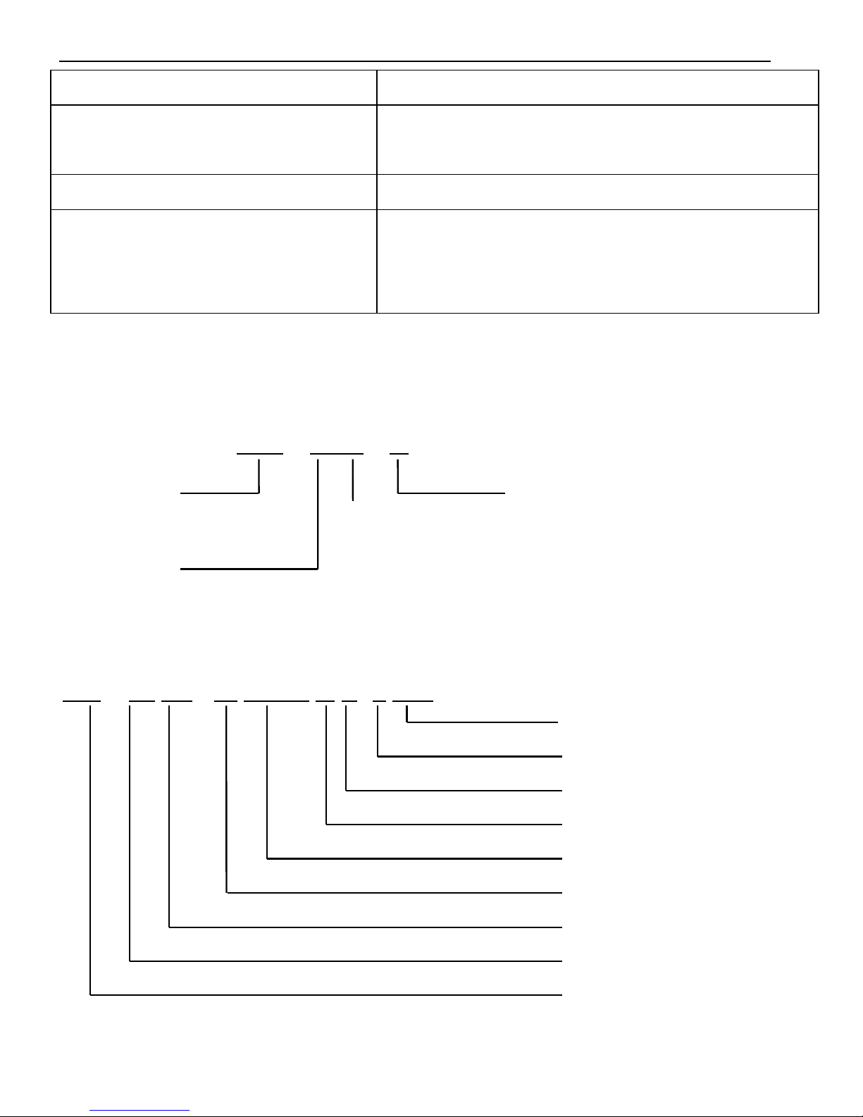
2. Model description
1)Servo drive
DS2 – 45P5 – A
2)Servo motor
MS -180 ST - M 35015 A Z- 4 5P5
Capacity
Rated voltage
Power-loss brake
Shaft Specifications
Performance Specifications
Feedback Component
Sinewave-drive Motors
Base Size
Motor Series Name
Voltage level
4:380V
Series name
DS2:Series number
Suitable motor
capacity
5P5:5.5KW
7P5:7.5KW
Configure type
A: Standard configure
B: Economical configure
(Without DB15 port)
Null: Fundamental configure
4
Base size:180;
Feedback component: M(Photoelectric pulse coder);
Performance Specifications: First 3 numbers mean rated torque, last 2 numbers mean rated
revolution;
For instance:35015:rated torque 35N·m,rated revolution 1500rpm;
48015:rated torque 48N·m,rated revolution 1500rpm;
Shaft Specifications:A-Without key;B-With key;
Power-loss brake:Null-Have it;Z-Not have it;
Voltage level:4-380V;
Capacity:5.5KW、7.5KW.
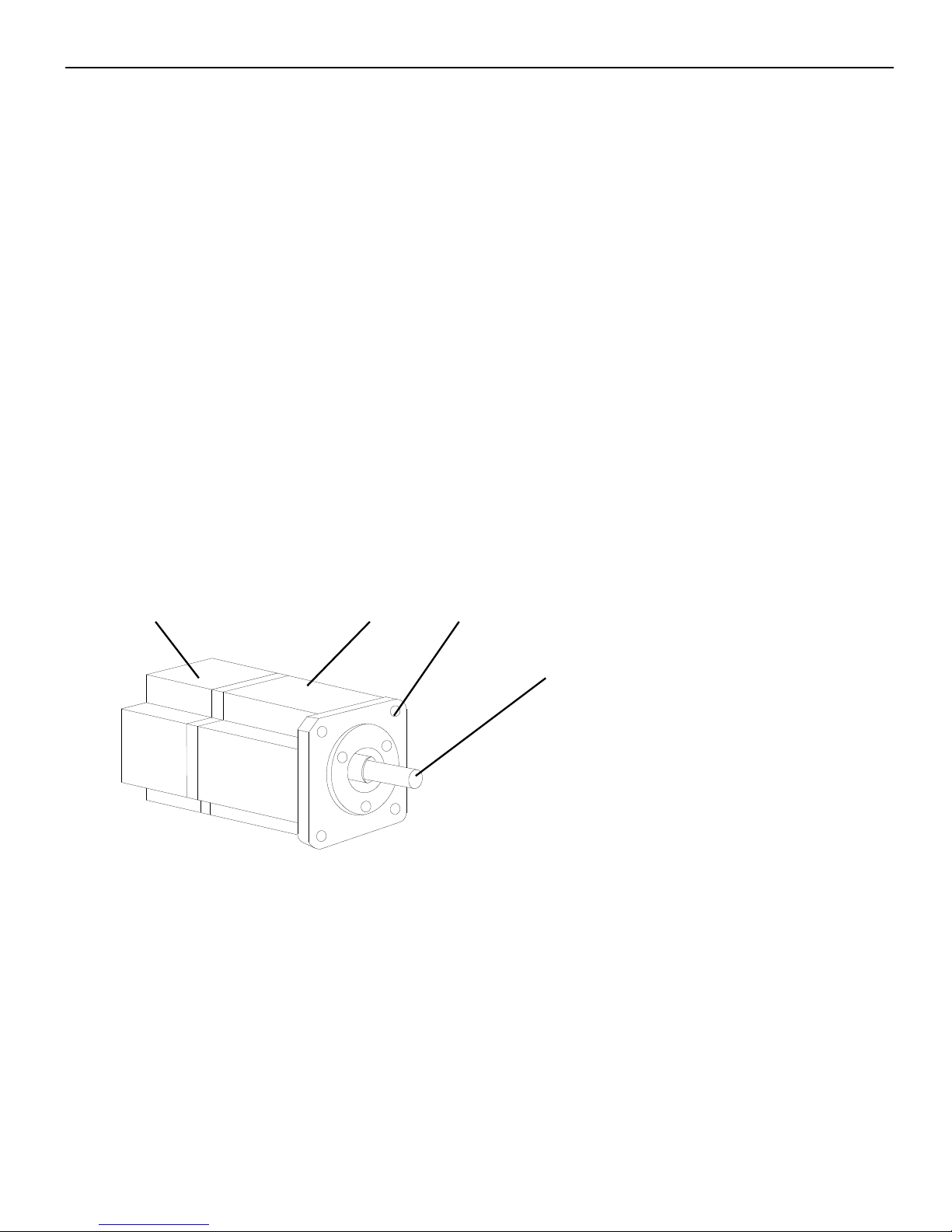
3. Sections description
1)Servo motor
Encoder code
Frame
Flange
Output (transmission) shaft
5
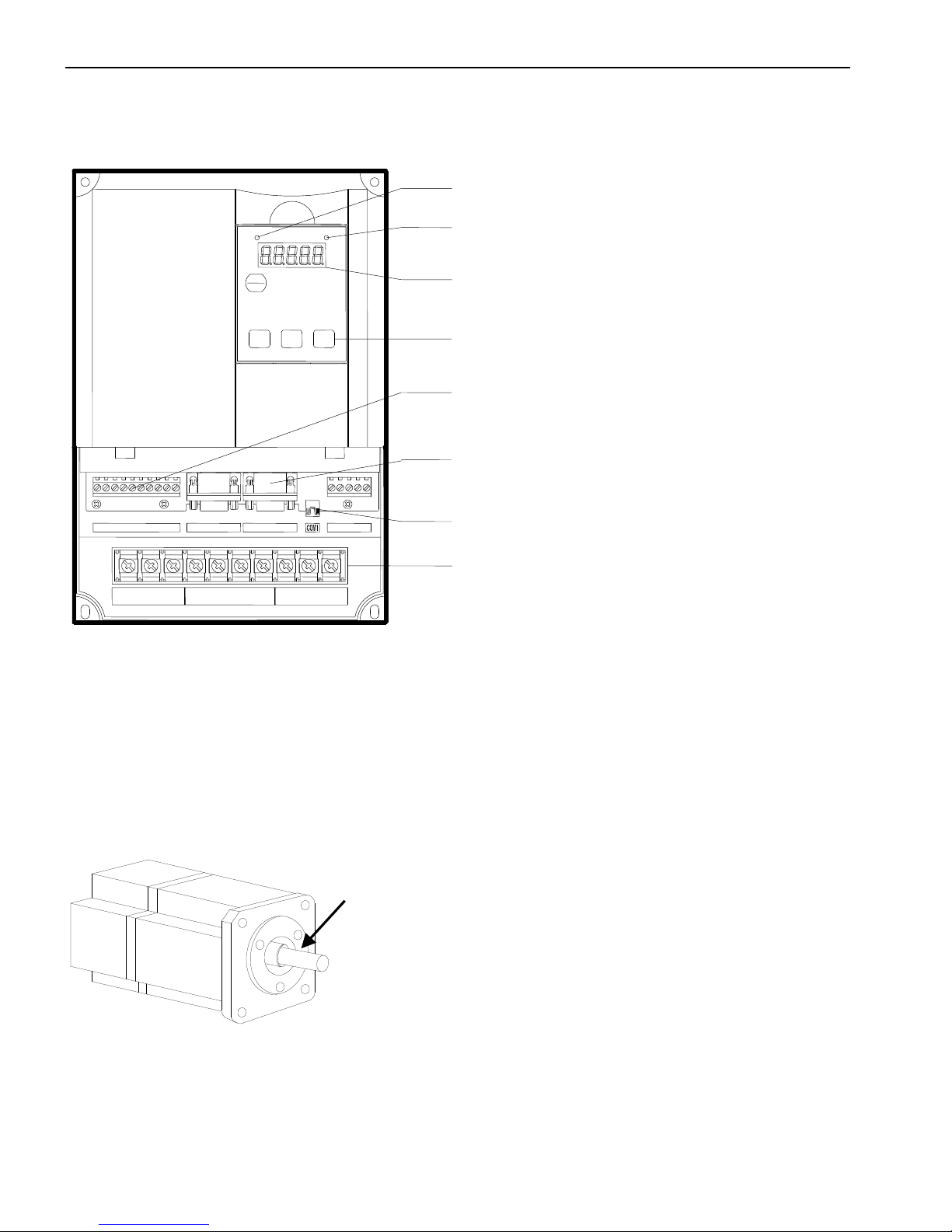
2)Servo drive
►► Installations
1. Servomotor
MS series servomotors can be installed either horizontally or vertically. The service
life of the servomotor can be shortened or unexpected problems might occur if it is installed
incorrectly or in an inappropriate location.
1) Storage Temperature
Store the servomotor within -20~+60 ℃ as long as it is stored with the power cable
disconnected.
To set the parameters
CN0/CN1/CN3
To connect the I/O signal and RS485 communication port
CN2
To connect the encoder on the servo motor
COM1
Connect to PC, HMI, PLC
Power supply and servo motor terminals
Power supply input, servo motor terminals
STA
ESC
INC
DEC
ENTER
POWER
CHARGE
R S T
P+
PB
P-
PE U V
W
CN1
CN2
CN0
CN3
POWER LED
Turn on when the drive power on
CHARGE LED
Turn on when main circuit power on.
Panel display
Show the servo state, alarm and parameters
Panel keys
Caution:
1. The end of the motor shaft is coated with antirust.
Before installing, carefully remove all of the paint using a
cloth moistened with paint thinner.
2. Avoid getting thinner on other parts of the servomotor.
Antirust

6
2) Installation Site
Indoor,free of corrosive or explosive gases.
Well-ventilated and free of dust and moisture.
Ambient temperature of 0° to 50°C.
Relative humidity (r.h.) of 20 to 90% with no condensation.
Accessible for inspection and cleaning.
3) Concentricity
Please use coupling when connecting to machine; keep the shaft center of servo motor
and machine at the same line. It should be accord to the following diagram when installing
the servo motor.
Caution:(1)If the concentricity is not enough, it will cause the vibration and bearing damage.
(2)When installing the coupler, prevent direct impact to the shaft. This can damage
the encoder mounted on the shaft end at the opposite side of the load.
4) Orientation
MS series servomotors can be installed either horizontally or vertically.
5) Handling Oil and Water
Install a protective cover over the
servomotor if it is used in a location that is
subject to water or oil mist. Also use a
servomotor with an oil seal when needed to
Measure it at 4 places of the circle, the difference should be
below 0.03mm. (Rotate with the shaft coupler)
Measure it at 4 places of the circle, the difference should be
below 0.03mm. (Rotate with the shaft coupler)
Through part of the shaft

7
seal the through-shaft section.
6) Cable Stress
Make sure that the power lines are free from bends and tension. Be especially careful to
wire signal line cables so that they are not subject to stress because the core wires are very
thin, measuring only 0.2 to 0.3mm2.
2. Servo drive
The DS2 series servo drives are base-mounted servo drives. Incorrect installation will
cause problems. Follow the installation instructions below.
1)Storage Conditions
Store the servo drive within -20~+85℃, as long as it is stored with the power cable
disconnected.
2)Installation Site
The following precautions apply to the installation site:
Situation
Installation Precaution
Installation in a
Control Panel
Design the control panel size, unit layout, and cooling method so the
temperature around the servo drives does not exceed 50°C.
Installation Near a
Heating Unit
Minimize heat radiated from the heating unit as well as any
temperature rise caused by natural convection so the temperature
around the servo drives does not exceed 50°C.
Installation Near a
Source of Vibration
Install a vibration isolator beneath the servo drive to avoid subjecting it
to vibration.
Installation at a Site
Exposed to
Corrosive Gas
Corrosive gas does not have an immediate effect on the servo drives,
but will eventually cause electronic components and terminals to
malfunction. Take appropriate action to avoid corrosive gas.
Other Situations
Do not install the servo drive in hot and humid locations or locations
subject to excessive dust or iron powder in the air.
8
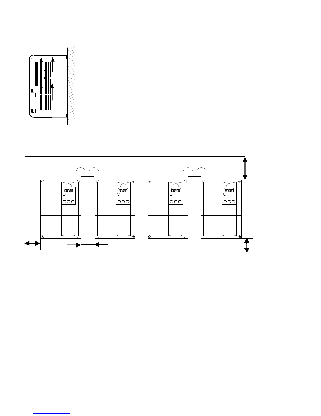
3)Orientation
4)Installation
Follow the procedure below to install multiple servo drives side by side in a control panel.
CHARGEPOWER
ENTERDECINC
ESC
STA STA
ESC
INC DEC ENTER
POWER CHARGECHARGEPOWER
ENTERDECINC
ESC
STASTA
ESC
INC DEC ENTER
POWER CHARGE
Servo drive Orientation
Install the servo drive perpendicular to the wall so the front panel containing connectors
faces outward.
Cooling
As shown in the figure above, allow sufficient space around each servo drive for
cooling by cooling fans or natural convection.
Side-by-side Installation
When install servo drives side by side as shown in the figure above, make at least 10mm
between and at least 50mm above and below each servo drive. Install cooling fans above the
servo drives to avoid excessive temperature rise and to maintain even temperature inside the
Install the servo drive perpendicular to the wall as
shown in the figure. The servo drive must be
oriented this way because it is designed to be cooled
by natural convection or by a cooling fan.
30mm minimum
50mm minimum
50mm minimum
10mm minimum
Wall
Ventilation

9
control panel.
Environmental Conditions in the Control Panel
Ambient Temperature: 0~50 ℃
Humidity: 90%RH or less
Vibration: 4.9m/s2
Condensation and Freezing: None
Ambient Temperature for Long-term Reliability: 50°C maximum
►► Dimensions
1. Servo motor
180 Series(Units: mm)
180
4- 13.5
200
233
180
3
51
65
LA
3.2
18
A
A
10 0-0.022
30 0-0.2
35
0
-0.025
114.3
0
-0.035
Type
LA
Normal
Band-type brake
MS-180ST-M21520□□-44P5
243
300
10
MS-180ST-M27015□□-44P3
262
319
MS-180ST-M35015□□-45P5
292
349
MS-180ST-M48015□□-47P5
346
403
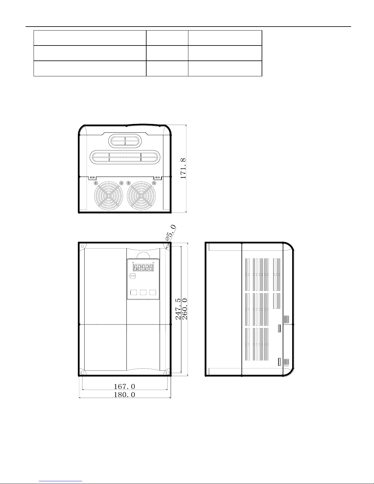
2. Servo drive(Units: mm)
DS2-45P5-A
STA
ESC
INC DEC
ENTER
POWER CHARGE

11
DS2-47P5-A
* STORED CHARGE DO NOT TOUCH UNTIL
10 MIN. AFTER DISCONNECTION
* RISK OF ELECTRIC SHOCK-DUAL SUPPLY
DISCONNECT MAINS AND LOADSHARING
WARNING
!
* DO NOT CONNECT AC POWER TO OUTPUT
TERMINALS OF "U V W"
BEFORE SERVICE
STA
ESC
420.0
230.0
160.0
400.0
120.0
217.6
ENTER
CHARGE POWER
12
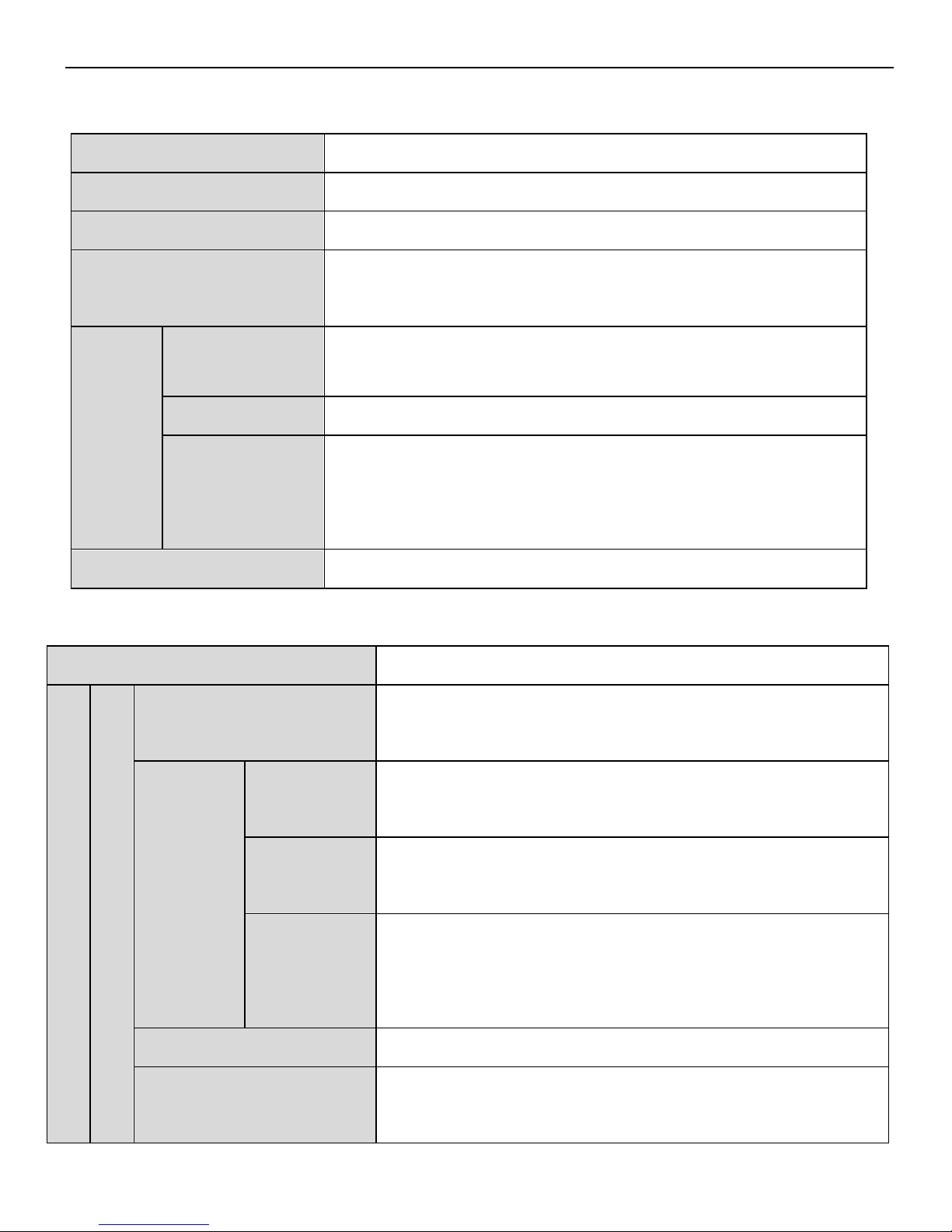
►► Servo drive general specification
Servo unit
DS2 series 380V servo drive
Encoder
Incremental encoder (2500 ppr)
Input power
DS2-4□P□-A:3-phase AC380V,50/60Hz
Control mode
3-phase full-wave rectifier control IPM PWM sine-wave
current drive
Using
Temperature
0~+50 ℃/-20~+85 ℃
Humidity
Below 90% RH (no condensation)
Vibration
/impact
resistance
4.9m/s
2
/ 19.6m/s2
Structure
Base installation
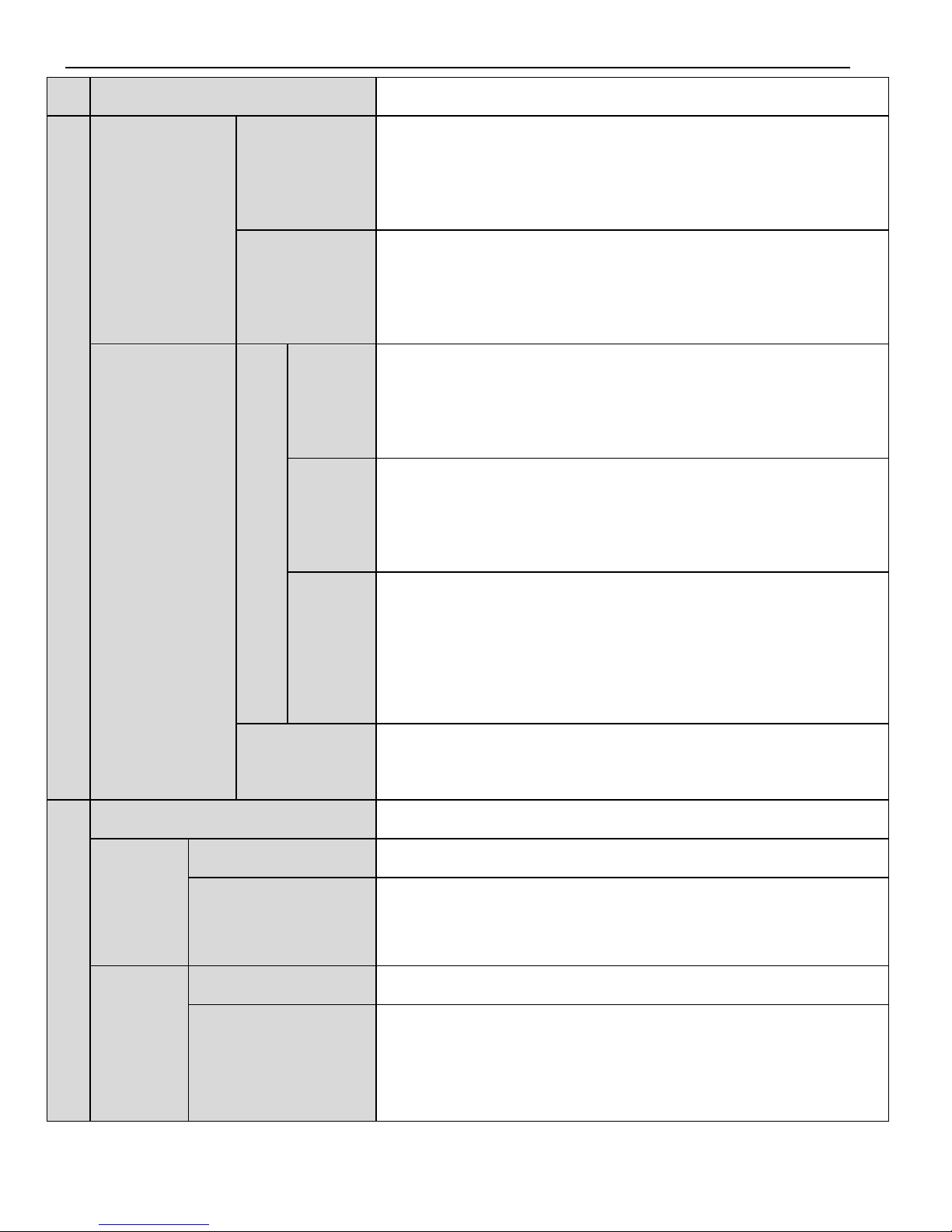
Performance specification
Servo drive type
DS2-45P5-A、DS2-47P5-A
Speed torque control mode
Performance
Speed control range
1:2500 (the lower limit of speed control range, not stop
at rated load torque)
Speed change rate
Load
change rate
0~100% load: below ±0.01% (rated speed)
Voltage
change rate
Rated voltage ±10% : 0% (rated speed)
Temperatur
e change
rate
20±25℃: below ±0.1% (rated speed)
Frequency feature
250Hz(JL≤JM)
Soft start time
0~65535ms(set acceleration, deceleration
individually)
13
Input signal
RS485
Position control mode
Performance
Feedforward
compensatio
n
0~100% (resolution is 1%)
Positioning
finished
width
0~250 command unit (resolution is 1 command unit)
Input signal
Command pulse
Input
pulse
type
Sign+ pulse, CW, CCW mode
Input
pulse
state
Collector (+24V) and differential signal input
Input
pulse
freque
ncy
Open collector input: 200kHZ
Differential input: 500kHZ
Control
signal
Clear signal (/CLR)
I/O signal
Position output
open collector output
Input
signal
External input
6
Changeable signal
distribution
/S-ON、/P-CON、/P-OT、/N-OT、/ALM-RST、/PCL、
/NCL、/SPD-D、/SPD-A、/SPD-B、/C-SEL、/ZCLAMP、
/CLR、/G-SEL、/CHGSTP
Output
signal
External output
3
Changeable signal
distribution
/COIN、/V-CMP、/TGON、/S-RDY、/CLT、/VLT、
/BK、/WARN、/NEAR、/ALM、/Z
 Loading...