

Page 1
WUXI XINJE ELECTRIC CO., LTD.
DS2 series 380V servo drive
Fast reference manual
Serial NO. SC2309 20120215 1.0
Page 2
2
►► Safety caution
Confirmation when receive products
DO NOT install any driver which is damaged, lack of accessories or not the same
with the model ordered.
Installation
Cut off external power supply before installation.
Wiring
Cut off external power supply before wiring.
Connect AC power supply to the corresponding terminals.
Do not connect a three-phase power supply to the U, V, or W output terminals.
Use 2mm2 wire to grounding the ground terminals.
Operation
Do not remove the panel cover while the power is ON.
Do not touch terminals for five minutes after the power has been turned OFF.
Do not connect with any motor when trial operation.
Before starting operation with a machine connected, change the settings to match
the parameters of the machine.
Do not attempt to change wiring while the power is ON.
Do not touch the heat sinks during operation.
►► Checking Products upon Delivery
1. When receive the products, please check below items:
Items
Comments
Are the delivered products the ones
that were ordered?
Check the model numbers marked on the nameplates
of the servomotor and servo drive.
Does the servomotor shaft rotate
smoothly?
The servomotor shaft is normal if it can be turned
smoothly by hand. Servomotors with brakes,
Page 3
3
however, cannot be turned manually.
Is there any damage?
Check the overall appearance, and check for damage
or scratches that may have occurred during shipping.
Are there any loose screws?
Check screws for looseness using a screwdriver.
Is the motor code the same with the
code in driver?
Check the motor code marked on the nameplates of
the servomotor and the parameter F0-00 on the servo
drive.
If any of the above is faulty or incorrect, contact XINJE or an authorized distributor.
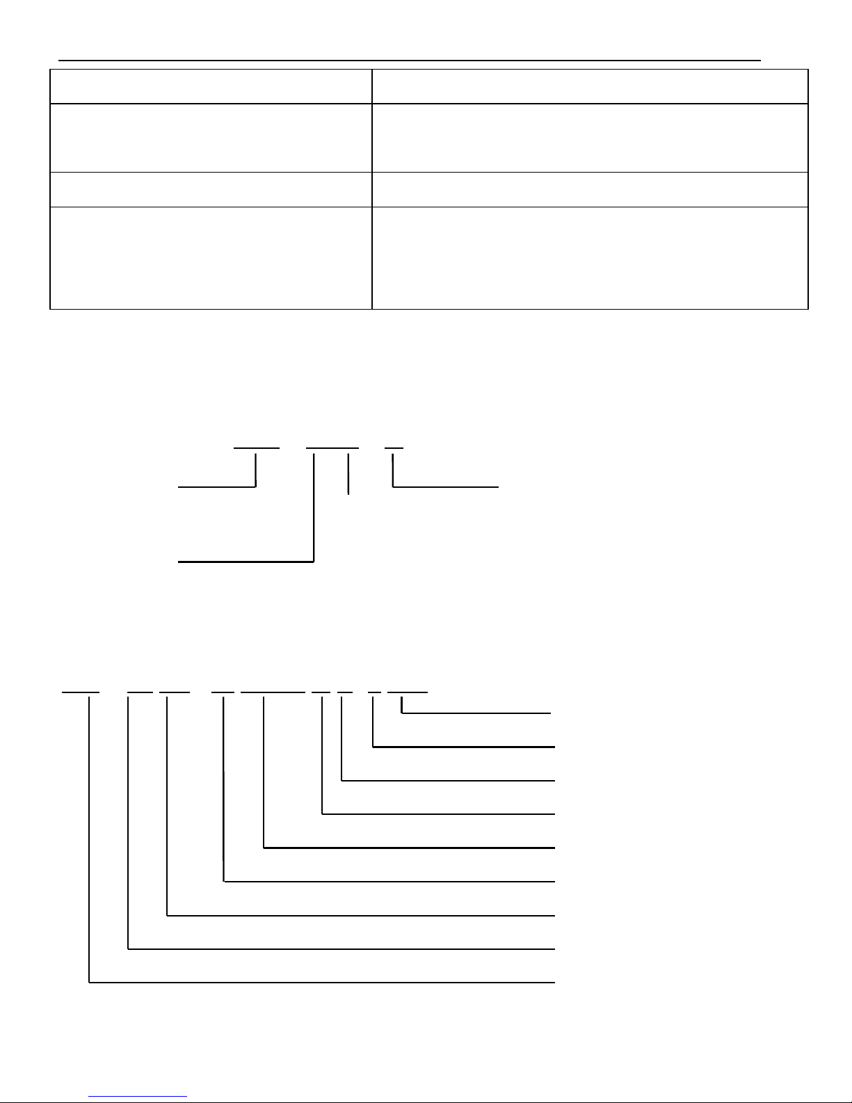
2. Model description
1)Servo drive
DS2 – 45P5 – A
2)Servo motor
MS -180 ST - M 35015 A Z- 4 5P5
Capacity
Rated voltage
Power-loss brake
Shaft Specifications
Performance Specifications
Feedback Component
Sinewave-drive Motors
Base Size
Motor Series Name
Voltage level
4:380V
Series name
DS2:Series number
Suitable motor
capacity
5P5:5.5KW
7P5:7.5KW
Configure type
A: Standard configure
B: Economical configure
(Without DB15 port)
Null: Fundamental configure
Page 4
4
Base size:180;
Feedback component: M(Photoelectric pulse coder);
Performance Specifications: First 3 numbers mean rated torque, last 2 numbers mean rated
revolution;
For instance:35015:rated torque 35N·m,rated revolution 1500rpm;
48015:rated torque 48N·m,rated revolution 1500rpm;
Shaft Specifications:A-Without key;B-With key;
Power-loss brake:Null-Have it;Z-Not have it;
Voltage level:4-380V;
Capacity:5.5KW、7.5KW.
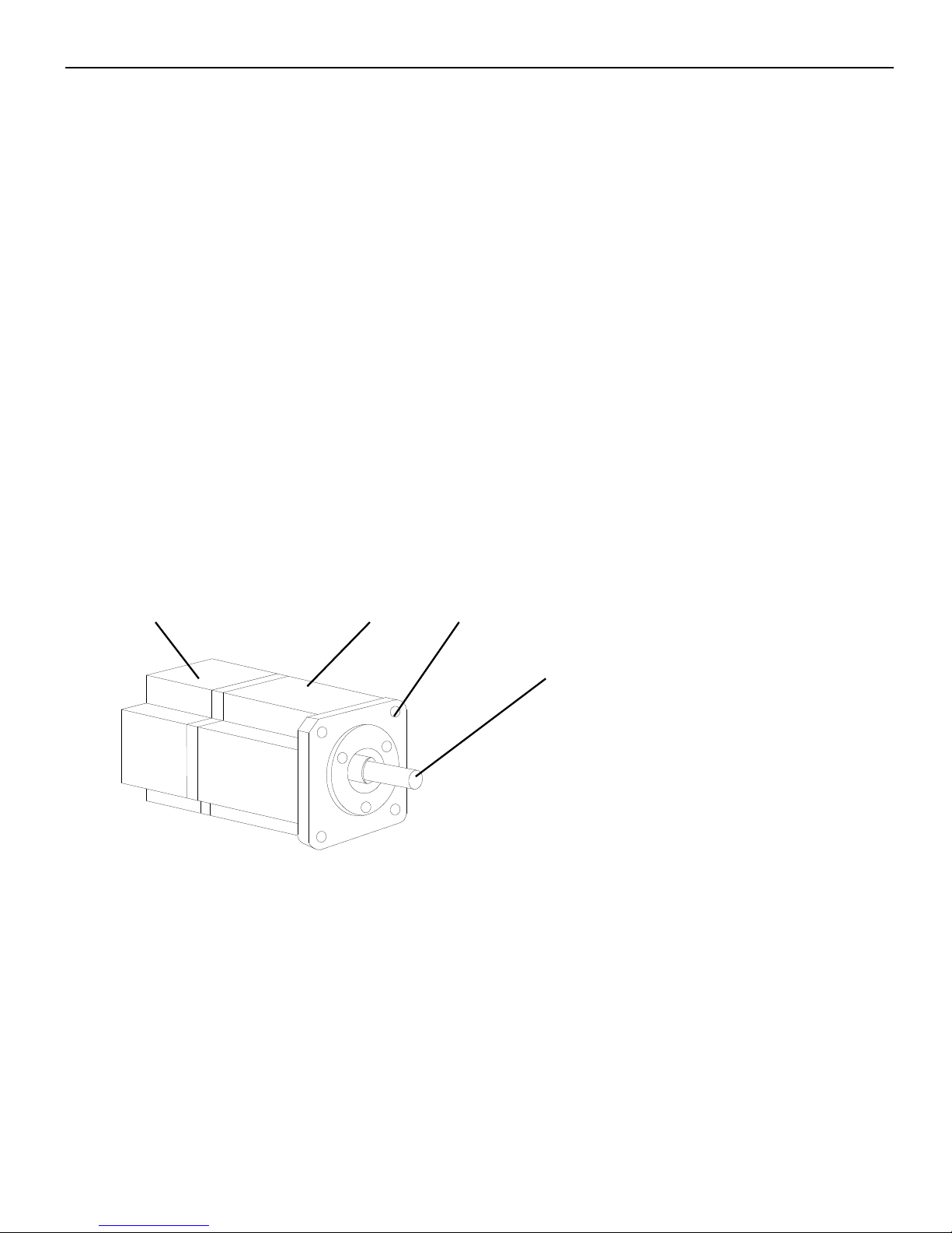
3. Sections description
1)Servo motor
Encoder code
Frame
Flange
Output (transmission) shaft
Page 5
5
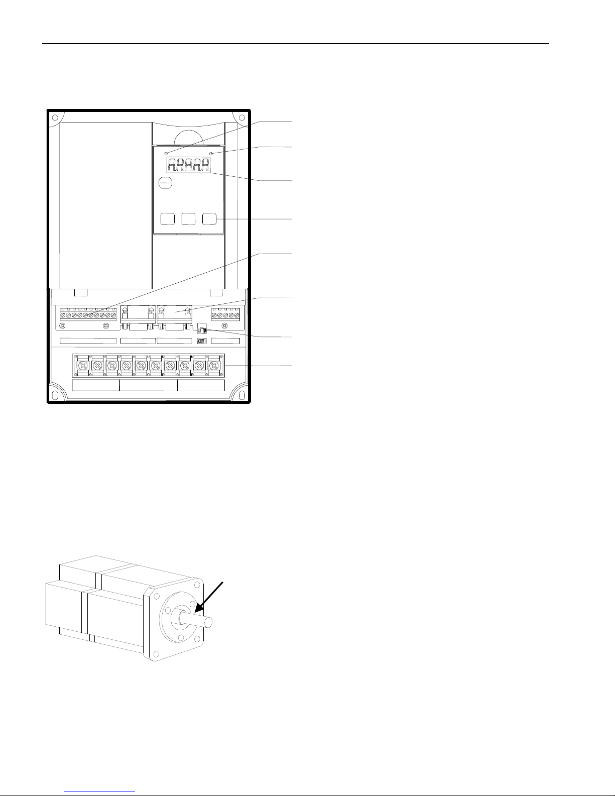
2)Servo drive
►► Installations
1. Servomotor
MS series servomotors can be installed either horizontally or vertically. The service
life of the servomotor can be shortened or unexpected problems might occur if it is installed
incorrectly or in an inappropriate location.
1) Storage Temperature
Store the servomotor within -20~+60 ℃ as long as it is stored with the power cable
disconnected.
To set the parameters
CN0/CN1/CN3
To connect the I/O signal and RS485 communication port
CN2
To connect the encoder on the servo motor
COM1
Connect to PC, HMI, PLC
Power supply and servo motor terminals
Power supply input, servo motor terminals
STA
ESC
INC
DEC
ENTER
POWER
CHARGE
R S T
P+
PB
P-
PE U V
W
CN1
CN2
CN0
CN3
POWER LED
Turn on when the drive power on
CHARGE LED
Turn on when main circuit power on.
Panel display
Show the servo state, alarm and parameters
Panel keys
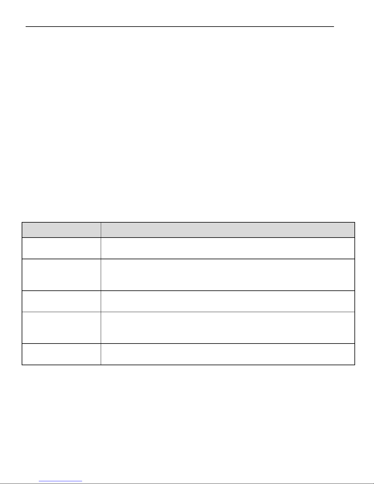
Caution:
1. The end of the motor shaft is coated with antirust.
Before installing, carefully remove all of the paint using a
cloth moistened with paint thinner.
2. Avoid getting thinner on other parts of the servomotor.
Antirust
Page 6

6
2) Installation Site
Indoor,free of corrosive or explosive gases.
Well-ventilated and free of dust and moisture.
Ambient temperature of 0° to 50°C.
Relative humidity (r.h.) of 20 to 90% with no condensation.
Accessible for inspection and cleaning.
3) Concentricity
Please use coupling when connecting to machine; keep the shaft center of servo motor
and machine at the same line. It should be accord to the following diagram when installing
the servo motor.
Caution:(1)If the concentricity is not enough, it will cause the vibration and bearing damage.
(2)When installing the coupler, prevent direct impact to the shaft. This can damage
the encoder mounted on the shaft end at the opposite side of the load.
4) Orientation
MS series servomotors can be installed either horizontally or vertically.
5) Handling Oil and Water
Install a protective cover over the
servomotor if it is used in a location that is
subject to water or oil mist. Also use a
servomotor with an oil seal when needed to
Measure it at 4 places of the circle, the difference should be
below 0.03mm. (Rotate with the shaft coupler)
Measure it at 4 places of the circle, the difference should be
below 0.03mm. (Rotate with the shaft coupler)
Through part of the shaft
Page 7
7
seal the through-shaft section.
6) Cable Stress
Make sure that the power lines are free from bends and tension. Be especially careful to
wire signal line cables so that they are not subject to stress because the core wires are very
thin, measuring only 0.2 to 0.3mm2.
2. Servo drive
The DS2 series servo drives are base-mounted servo drives. Incorrect installation will
cause problems. Follow the installation instructions below.
1)Storage Conditions
Store the servo drive within -20~+85℃, as long as it is stored with the power cable
disconnected.
2)Installation Site
The following precautions apply to the installation site:
Situation
Installation Precaution
Installation in a
Control Panel
Design the control panel size, unit layout, and cooling method so the
temperature around the servo drives does not exceed 50°C.
Installation Near a
Heating Unit
Minimize heat radiated from the heating unit as well as any
temperature rise caused by natural convection so the temperature
around the servo drives does not exceed 50°C.
Installation Near a
Source of Vibration
Install a vibration isolator beneath the servo drive to avoid subjecting it
to vibration.
Installation at a Site
Exposed to
Corrosive Gas
Corrosive gas does not have an immediate effect on the servo drives,
but will eventually cause electronic components and terminals to
malfunction. Take appropriate action to avoid corrosive gas.
Other Situations
Do not install the servo drive in hot and humid locations or locations
subject to excessive dust or iron powder in the air.
Page 8
8
3)Orientation
4)Installation
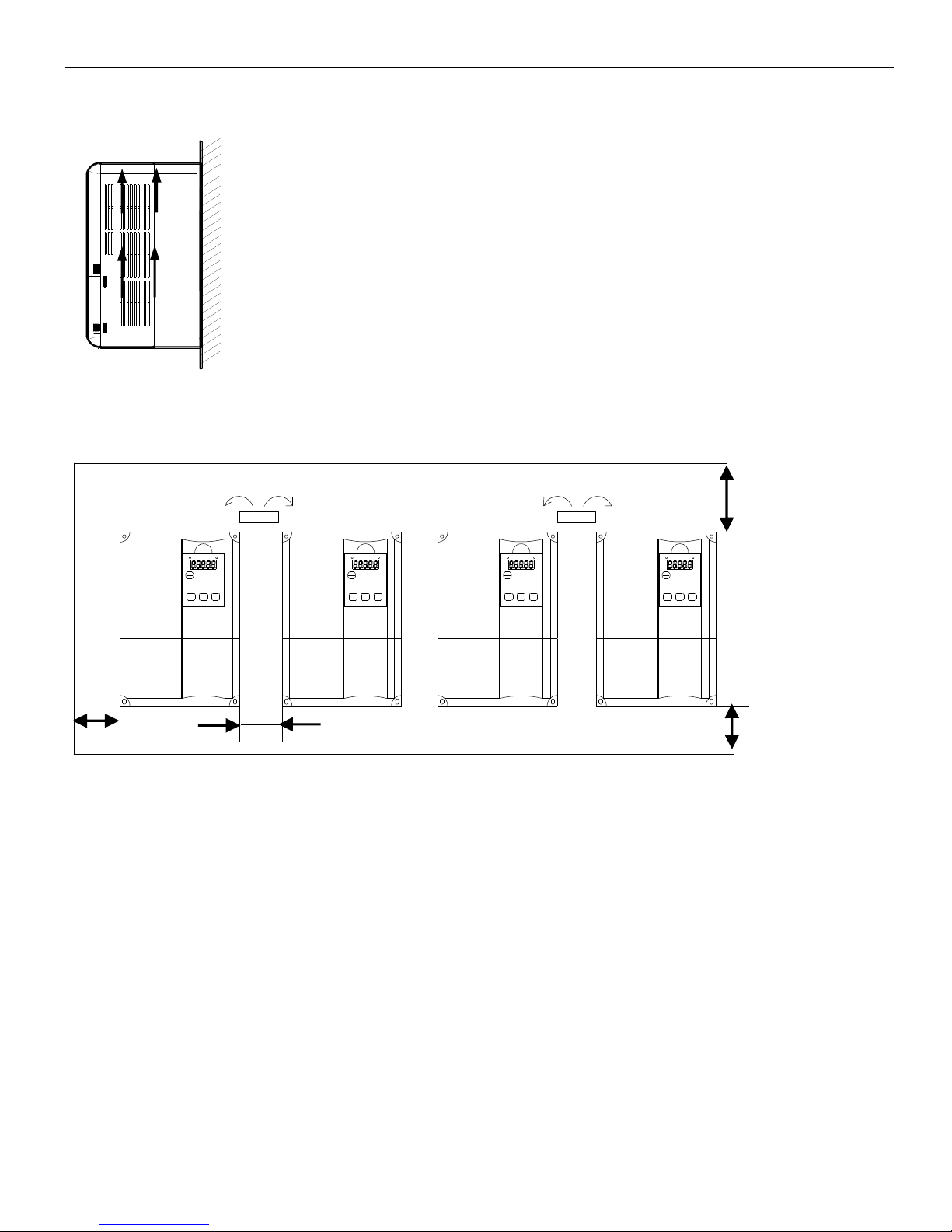
Follow the procedure below to install multiple servo drives side by side in a control panel.
CHARGEPOWER
ENTERDECINC
ESC
STA STA
ESC
INC DEC ENTER
POWER CHARGECHARGEPOWER
ENTERDECINC
ESC
STASTA
ESC
INC DEC ENTER
POWER CHARGE
Servo drive Orientation
Install the servo drive perpendicular to the wall so the front panel containing connectors
faces outward.
Cooling
As shown in the figure above, allow sufficient space around each servo drive for
cooling by cooling fans or natural convection.
Side-by-side Installation
When install servo drives side by side as shown in the figure above, make at least 10mm
between and at least 50mm above and below each servo drive. Install cooling fans above the
servo drives to avoid excessive temperature rise and to maintain even temperature inside the
Install the servo drive perpendicular to the wall as
shown in the figure. The servo drive must be
oriented this way because it is designed to be cooled
by natural convection or by a cooling fan.
30mm minimum
50mm minimum
50mm minimum
10mm minimum
Wall
Ventilation
Page 9

9
control panel.
Environmental Conditions in the Control Panel
Ambient Temperature: 0~50 ℃
Humidity: 90%RH or less
Vibration: 4.9m/s2
Condensation and Freezing: None
Ambient Temperature for Long-term Reliability: 50°C maximum
►► Dimensions
1. Servo motor
180 Series(Units: mm)
180
4- 13.5
200
233
180
3
51
65
LA
3.2
18
A
A
10 0-0.022
30 0-0.2
35
0
-0.025
114.3
0
-0.035
Type
LA
Normal
Band-type brake
MS-180ST-M21520□□-44P5
243
300
Page 10
10
MS-180ST-M27015□□-44P3
262
319
MS-180ST-M35015□□-45P5
292
349
MS-180ST-M48015□□-47P5
346
403
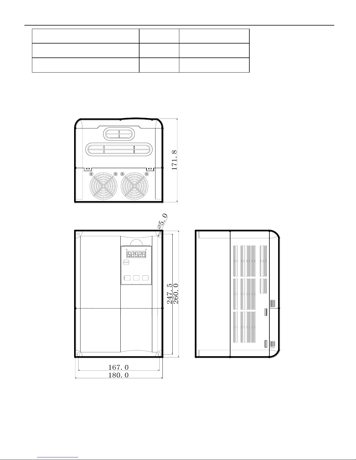
2. Servo drive(Units: mm)
DS2-45P5-A
STA
ESC
INC DEC
ENTER
POWER CHARGE
Page 11

11
DS2-47P5-A
* STORED CHARGE DO NOT TOUCH UNTIL
10 MIN. AFTER DISCONNECTION
* RISK OF ELECTRIC SHOCK-DUAL SUPPLY
DISCONNECT MAINS AND LOADSHARING
WARNING
!
* DO NOT CONNECT AC POWER TO OUTPUT
TERMINALS OF "U V W"
BEFORE SERVICE
STA
ESC
420.0
230.0
160.0
400.0
120.0
217.6
ENTER
CHARGE POWER
Page 12
12
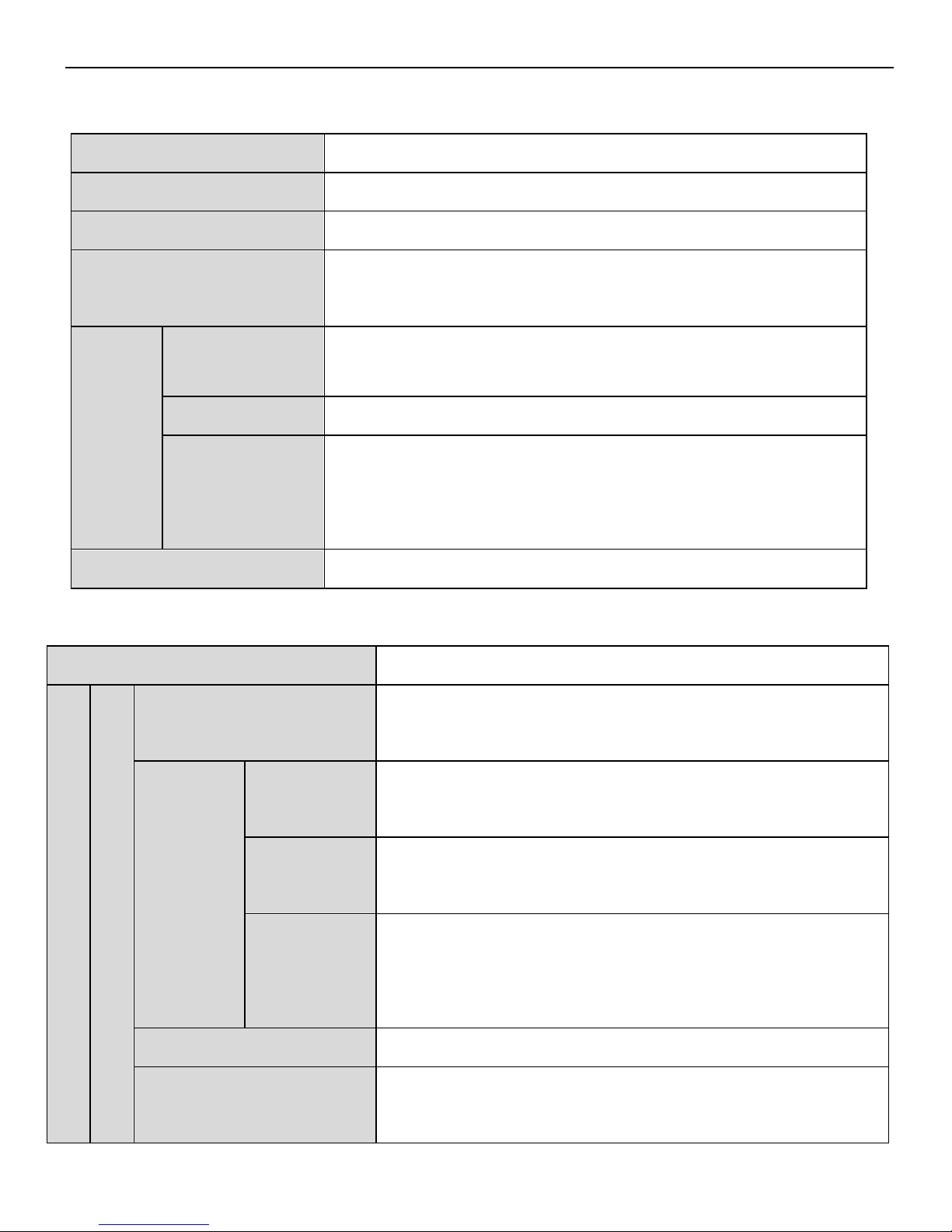
►► Servo drive general specification
Servo unit
DS2 series 380V servo drive
Encoder
Incremental encoder (2500 ppr)
Input power
DS2-4□P□-A:3-phase AC380V,50/60Hz
Control mode
3-phase full-wave rectifier control IPM PWM sine-wave
current drive
Using
Temperature
0~+50 ℃/-20~+85 ℃
Humidity
Below 90% RH (no condensation)
Vibration
/impact
resistance
4.9m/s
2
/ 19.6m/s2
Structure
Base installation
Performance specification
Servo drive type
DS2-45P5-A、DS2-47P5-A
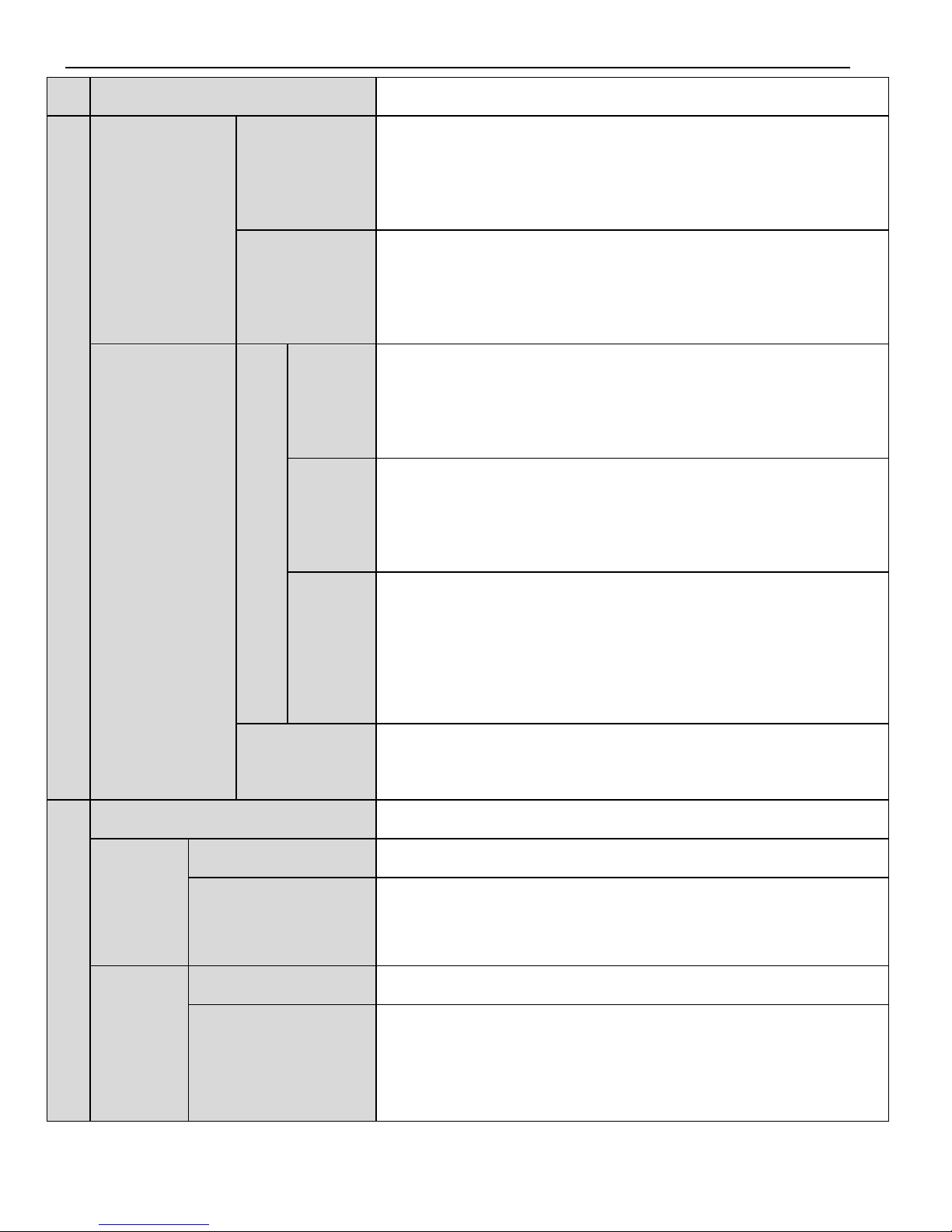
Speed torque control mode
Performance
Speed control range
1:2500 (the lower limit of speed control range, not stop
at rated load torque)
Speed change rate
Load
change rate
0~100% load: below ±0.01% (rated speed)
Voltage
change rate
Rated voltage ±10% : 0% (rated speed)
Temperatur
e change
rate
20±25℃: below ±0.1% (rated speed)
Frequency feature
250Hz(JL≤JM)
Soft start time
0~65535ms(set acceleration, deceleration
individually)
Page 13
13
Input signal
RS485
Position control mode
Performance
Feedforward
compensatio
n
0~100% (resolution is 1%)
Positioning
finished
width
0~250 command unit (resolution is 1 command unit)
Input signal
Command pulse
Input
pulse
type
Sign+ pulse, CW, CCW mode
Input
pulse
state
Collector (+24V) and differential signal input
Input
pulse
freque
ncy
Open collector input: 200kHZ
Differential input: 500kHZ
Control
signal
Clear signal (/CLR)
I/O signal
Position output
open collector output
Input
signal
External input
6
Changeable signal
distribution
/S-ON、/P-CON、/P-OT、/N-OT、/ALM-RST、/PCL、
/NCL、/SPD-D、/SPD-A、/SPD-B、/C-SEL、/ZCLAMP、
/CLR、/G-SEL、/CHGSTP
Output
signal
External output
3
Changeable signal
distribution
/COIN、/V-CMP、/TGON、/S-RDY、/CLT、/VLT、
/BK、/WARN、/NEAR、/ALM、/Z
Page 14
14
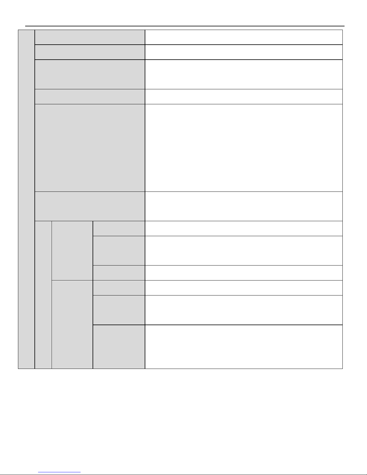
Built
-
in function
Dynamic brake (DB)
No
Regeneration
Built-in regeneration unit, external regenerative resistor
Over range(OT)protection
For P-OT, N-OT action, deceleration stop or inertia
stop
Electronic gear
0.01≤ B/A≤100
Protection
Program error, parameter error, overvoltage,
undervoltage, regeneration error, overtemperature,
overcurrent, overspeed, analog input error, position
offset overflow, output shorting, current error, encoder
cut, encoder error, overload, power off when running,
write parameter error…
LED display
Charge, power supply, 7-segment LED ×5 (built-in
digital operate)
communication
COM 1
Connector
RS232, connect to PC
Serial
parameter
Baud rate 19200; data bit 8; stop bit 1; communication
protocol: ModubsRTU slave; Modbus station No.1
Function
Debug online
COM 2
Connector
RS485, connect to PLC, HMI, PC and other devices
Serial
parameter
Serial parameter can be set; communication protocol:
ModbusRTU slave; Modbus station No. can be set
Function
State display, user constant setting, monitor display,
alarm display, alarm display, special control, online
debug
Page 15
15
►► Wiring
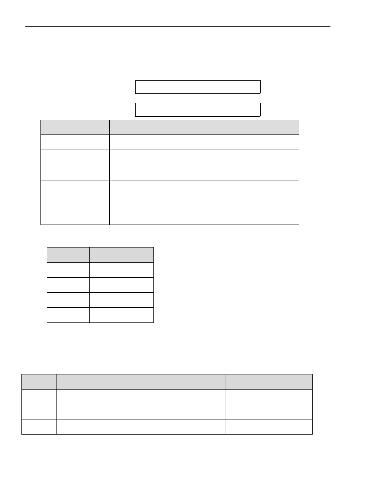
1. Names and Descriptions of Main Circuit Terminal
5.5KW driver:
R S T P+ PB P- PE U V W
7.5KW driver:
R S T
P+
PB
P-
PE
U V W
Terminal names
Function
R、S、T
3-phase AC 380V±10%(50/60Hz)
P+、PB
Regenerative braking resistor connection
P+、P-
Power supply for main circuit
PE
Ground (Connect to the ground terminal of motor
and power, to be grounded)
U、V、W
Motor connection
2. Winding Terminals on Servo motor
Symbol
180 Series
PE 1 U 2 V 3 W
4
3. Layout of CN0/CN1/CN3 terminals
The diagram shows the solder side:
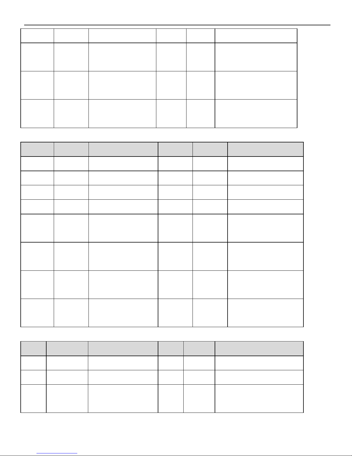
Terminals description of CN0
NO.
Name
Description
NO.
Name
Description
1
PUL-
Pulse input PUL-
6
V2+
+24V for open
collector
2
PUL+
Differential input
7
SI1
Input terminal 1
Page 16
16
PUL+
3
V1+
+24V for open
collector
8
SI2
Input terminal 2
4
DIR-
Direction input
DUL-
9
SI3
Input terminal 3
5
DIR+
Differential input
DIR+
10
+24V
+24V for input
Terminals description of CN1
NO.
Name
Description
NO.
Name
Description
1
NC
Null
9
BO
Encoder output B
2
SI4
Input terminal 4
10
ZO
Encoder output Z
3
SI5
Input terminal 5
11
T-REF
Torque analog input
4
SI6
Input terminal 6
12
V-REF
Speed analog input
5
+24V
+24V for input
13
GND
GND for analog
input
6
SO3
Output terminal 3
14
GND
GND for AO&BO
output
7
COM
Ground of output
terminal
15
GND
GND for ZO output
8
AO
Encoder
output A
Terminals description of CN3
NO.
Name
Description
NO.
Name
Description
1
SO1
Output terminal 1
4
A
RS485+
2
SO2
Output terminal 2
5
B
RS485-
3
COM
Ground of output
terminal
Page 17
17
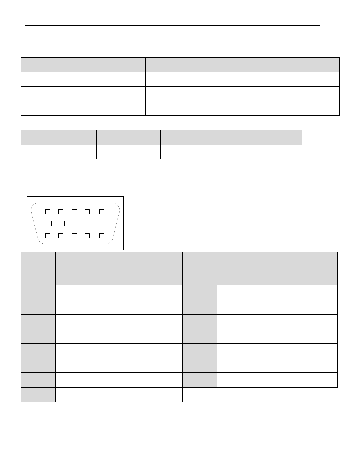
4. I/O Signal Names and Functions
1)Input signals
Item
Input terminal
Function
Digital input
SI1~SI6
Multi-functional input terminal
Pulse input
PUL-、PUL+/V1+
P2-00=0:A-phase pulse;P2-00=2:pulse
DIR-、DIR+/V2+
P2-00=0:B-phase pulse;P2-00=2:pusle direction (sign)
2)Output signals
Class
Output terminal
Function
Optocoupler output
SO1~SO3
Multi-functions Output Terminals
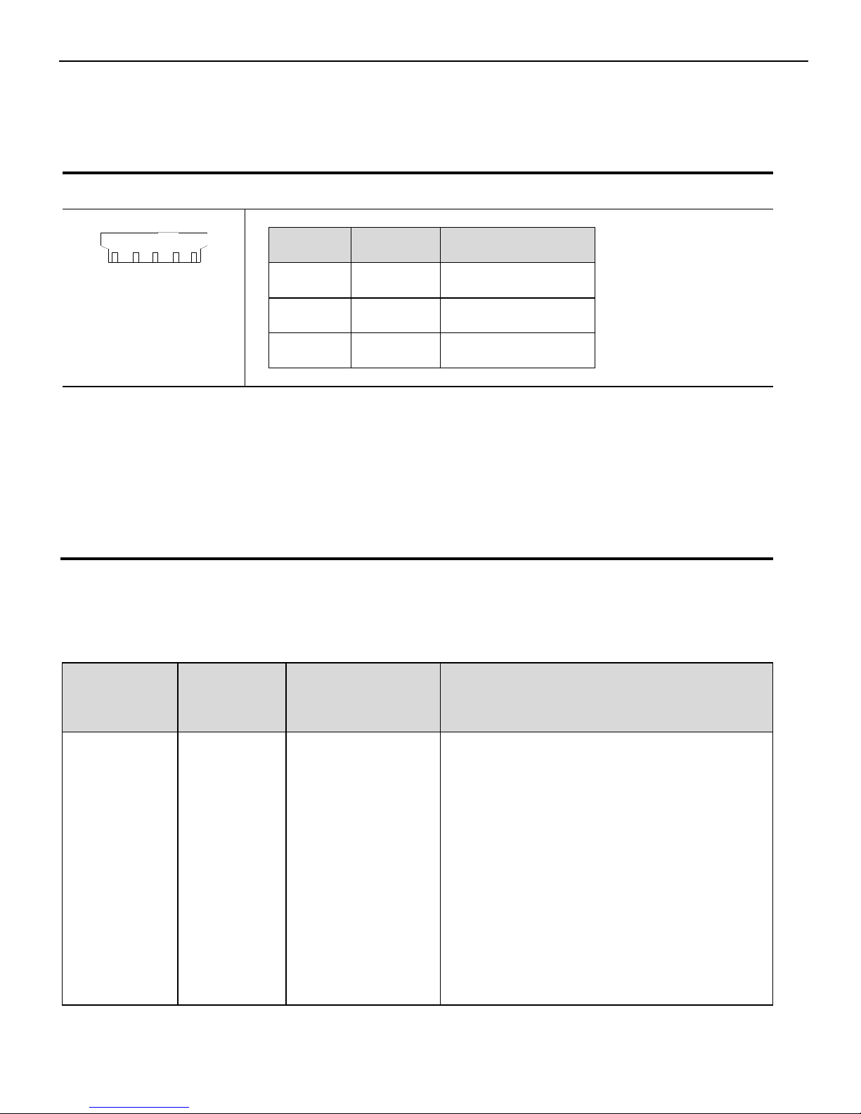
5. CN2 Connector Terminal Layout
The following diagrams are the layout of CN2 connector (face the solder pin).
910
15 14 13
12
11
1
2
345
6
7
8
Drive
side
Encoder Side On
Motor
Name
Drive
side
Encoder Side On
Motor
Name
180 series
180 series
1 4 A+ 2 5
B+ 3 6
Z+ 4 10
U+ 5 12
W+ 6 7
A- 7 8
B- 8 9
Z-
9
13
U-
10
15
W-
11 1 Shield
12 3 GND
13 2 5V
14
11
V+
15
14
V-
Page 18
18
6. Communication port
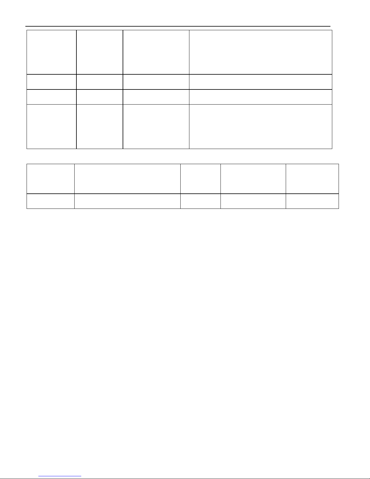
Serial Port 1(COM1)
COM1 supports RS232, and is often used to connect with PC for debugging.
DS2-45P5-A、DS2-47P5-A
1
5
(5-pin port)
Pin
Name
Description
1
TXD
RS232 send
2
RXD
RS232 receive
3
GND
RS232 ground
Caution:1. Please use the cable provided by XINJE company.
2. The types in the table cannot use RS232 (COM1) and RS485 (COM2) at
the same time.
The communication parameters of COM1 and COM2 will be changed at
the same time.
Serial Port(COM2) (Pin: A:CN3-4, B:CN3-5)
Communication parameters of COM2 can be set via P0-04.
Parameter
Number
Name
Default Setting
Range
P0-04.0
Baud rate
6
0~9
0:300
1:600
2:1200
3:2400
4:4800
5:9600
6:19200
Page 19
19
7:38400
8:57600
9:115200
P0-04.1
Data bits
0
0:8
P0-04.2
Stop bits
2
0:2 bits;2:1 bits
P0-04.3
Parity
2
0~2
0:No Parity;1:Odd Parity;2:Even
Parity
Modbus station number can be set freely, depending on the following parameter.
Parameter
Number
Name
Unit
Default setting
Range
P0-03
Modbus Station Number
- 1 1~255
Note: Parameters above will take effect after repower on.
Page 20
20
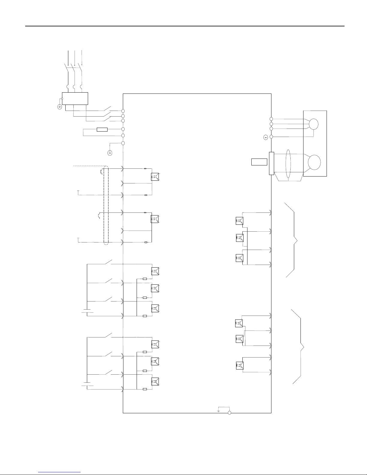
7. Standard connection example of DS2-45P5&47P5
Note: This is the standard connection diagram of open collector input (+24V).
3.3KΩ
3.3KΩ
3.3KΩ
3.3KΩ
3.3KΩ
3.3KΩ
FLT
M
PG
R S T U V
W
PE
PUL- CN0-1
DIR- CN0-4
V1+ CN0-3
CN2
P+
/SON CN0-7
/ALMRS CN0-8
/POT CN0-9
+24V CN0-10
PB
+24V CN1-5
CN1-10
CN1-9
CN1-8
CN1-13
CN3-1
CN3-2
CN3-3
CN1-6
CN1-7
COIN
COM
ALM
S-RDY
COM
Z0
B0
A0
GND
(50/60HZ)
Regenerative
resistor
The shield layer
connect
0V at signal side,
connect
nothing at servo
side
Servo enable
(ON is enable)
Alarm reset
(clear the alarm when ON)
Forward prohibited
(forward prohibited when ON)
Reverse prohibited
(reverse prohibited when ON)
Speed choice
Speed choice
Well operate with
the end of shield
cable
Encoder
output
Self-defined
output
PE U V
W
150Ω
CN0-2
24V
V1+ CN0-6
24V
CN0-5
3.3KΩ
3.3KΩ
150Ω
/N-OT CN1-2
/SPD-A CN1-3
/SPD-B CN1-4
3-phase 380V
Page 21
21
►► Using the operation panel
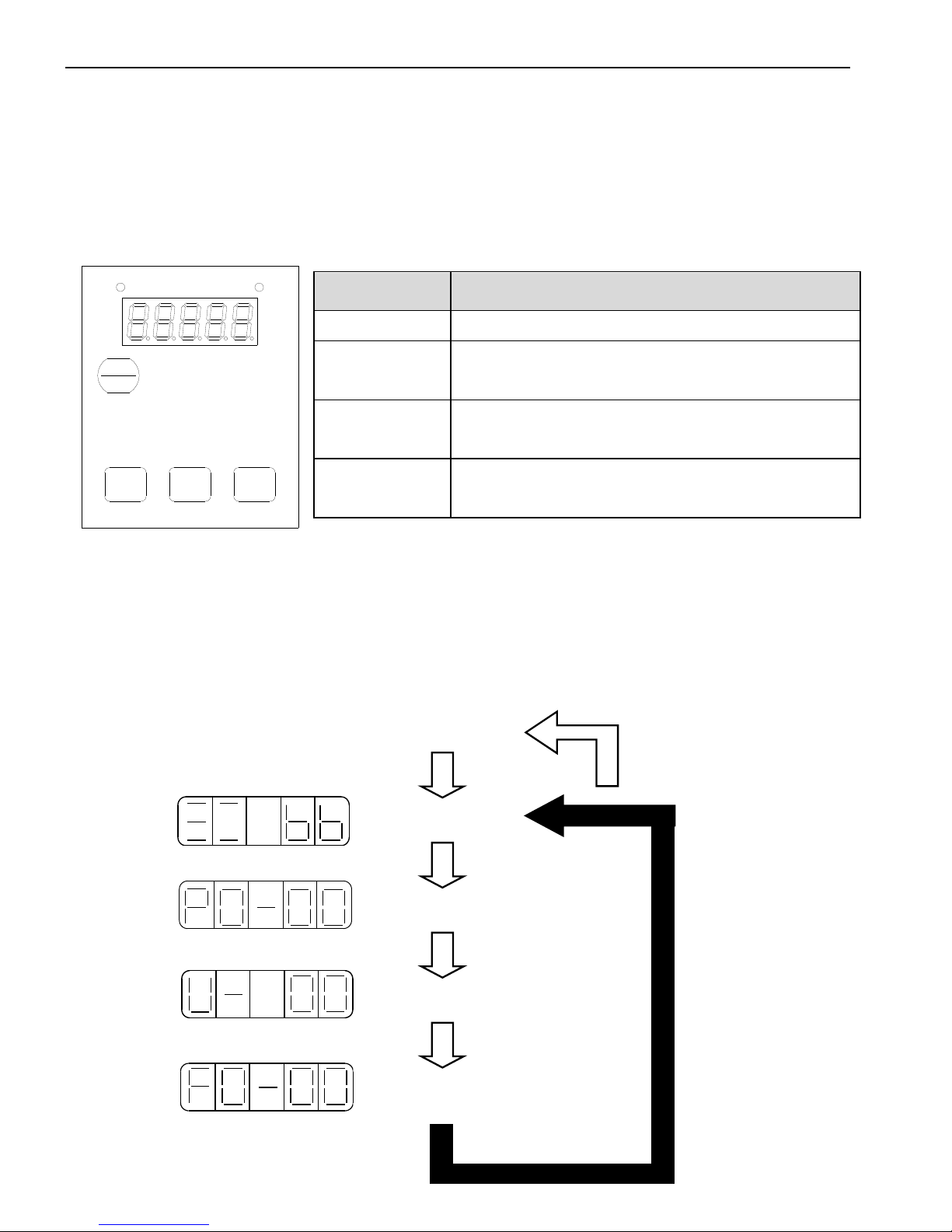
1. Basic operation
The operate panel can be used for parameter settings, operating references, and status
displays. 5-bit LED displays parameter settings, status or alarm.
STA
ESC
INC DEC
ENTER
POWER
CHARGE
The operate panel can display the status, set parameter and run the command by
switching the basic mode.
The running status, auxiliary function, parameter setting, and monitoring are the basic
modes. The modes switch as the below diagram by pressing STATUS/ESC.
Button name
Function
STA/ESC
Press: Status switch, status return
INC
Press: Increase the value;
Press and hold: Increase the value continuously
DEC
Press: Decrease the value;
Press and hold: Decrease the value continuously
ENTER
Press: Shift the editing digit;
Press and hold: Enter a status, check the data
Auxiliary function
Monitoring
Parameter setting
Running status
Power ON
Page 22
22
Display mode:
1. Monitor Function U- XX: XX means the number of the monitor function.
2. Auxiliary Function FX-XX: The first X means group No., the last two X means the
member No. in the group.
3. Parameter Setting PX-XX: The first X means group No., the last two X means the
member No. in the group.
4. Alarm E-XXX: XXX means the alarm code.
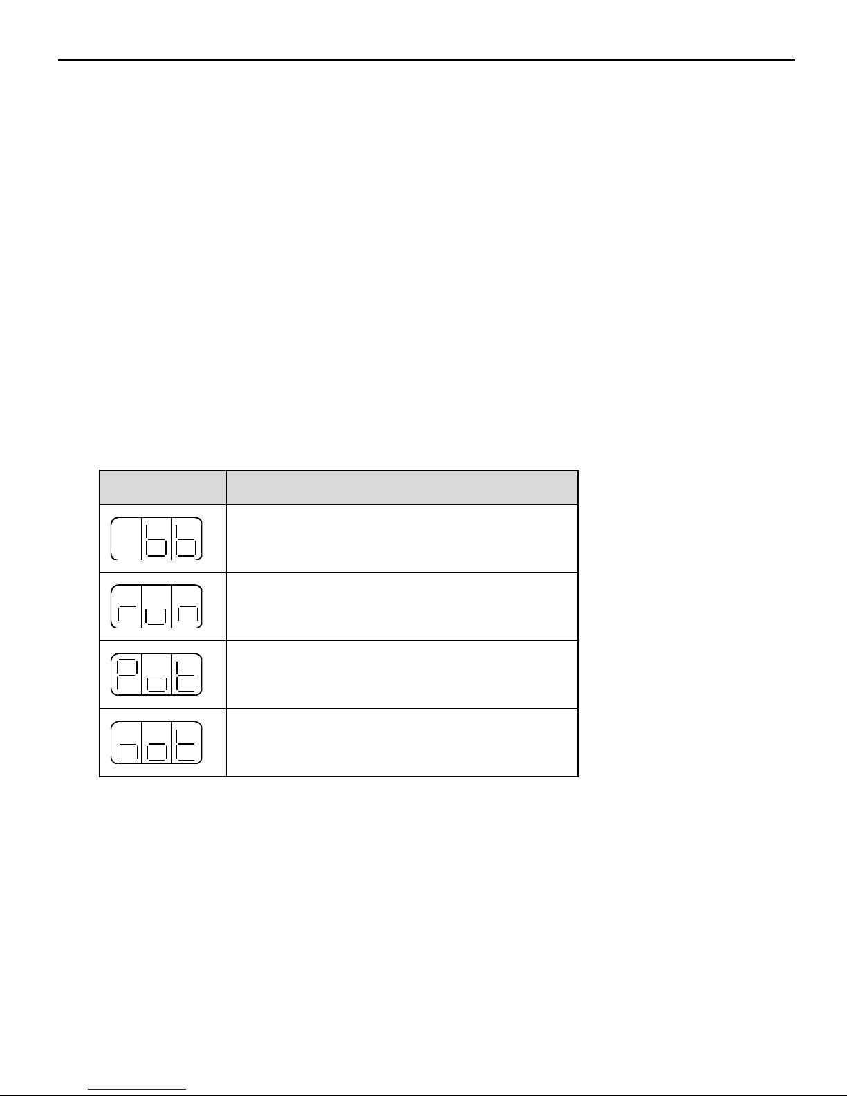
2. Running status mode
In running status mode, bit data and codes indicate the status of the servo drive.
Select the running status mode
The servo will enter running status when power on. If not, press STATUS/ESC to enter.
The display content of running status mode
Code
Description
Standby
Servo OFF (motor power OFF)
Run
Servo ON (motor power ON)
Forward Run Prohibited
P-OT is OFF
Reverse Run Prohibited
N-OT is OFF
3. Monitoring Mode
The Monitoring Mode can be used to monitor the reference values, I/O signal status, and
servo drive internal status. The monitor mode can be set when the motor is running.
Using the Monitor Mode
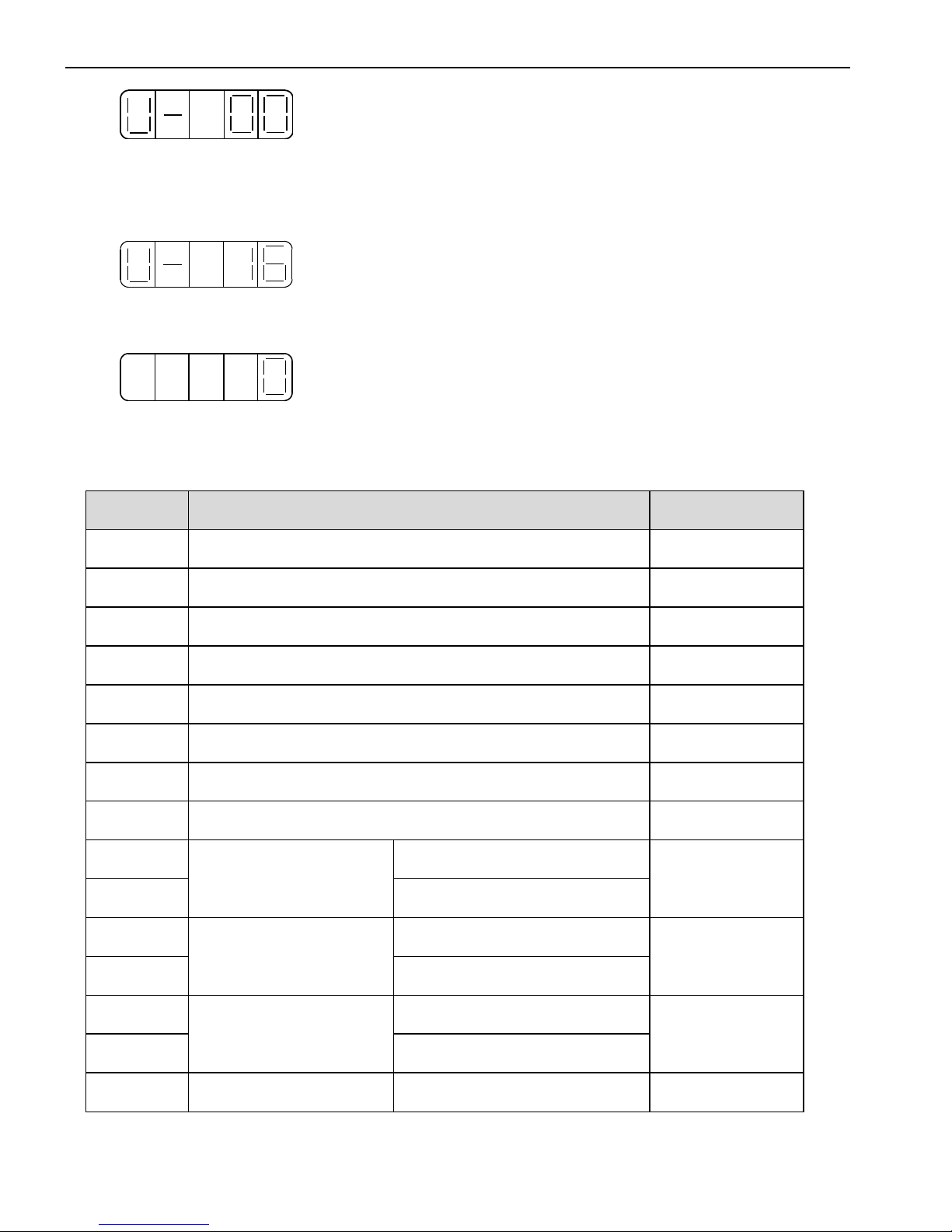
Now we take the monitor code U-16 as an example.
(1)Press the STATUS/ESC key to select the monitoring mode.
Page 23
23
(2)Press the INC or DEC key to select the monitor number U-16, and then press and hold
ENTER to enter the monitor mode.
(3)The value 0 is now displayed, means the driver is in a normal condition.
(4)Press STATUS/ESC key to return to the monitoring number switching state.
Display contents of Monitoring Mode
Number
Monitor Display
Unit
U-00
Actual speed of motor
Rpm
U-01
Input speed command
Rpm
U-02
Internal torque command
%
U-03
Rotate angle (mechanism angle)
0.1°
U-04
Rotate angle (electrical angle)
0.1°
U-05
Bus voltage
V
U-06
Module temperature
0.1℃
U-07
Input command pulse speed
Rpm
U-08
Pulse value of shift
command
(0000~9999)*1
Command
pulse
U-09
(0000~9999)*10000
U-10
Rotate angle
(encoder value)
(0000~9999)*1
encoder pulse
U-11
(0000~9999)*10000
U-12
Pulse value of input
command
(0000~9999)*1
Pulse
command
U-13
(0000~9999)*10000
U-14
Pulse value of
(0000~9999)*1
Pulse
Page 24
24
U-15
feedback command
(0000~9999)*10000
command
U-16
Current position
(Accumulated)
(0000~9999)*1
encoder pulse
U-17
(0000~9999)*10000
U-18
Current, 1-bit decimal
0.1A
U-19
Analog input V-REF
0.01V
U-20
Analog input T-REF
0.01V
U-21
I/O signals status
U-22
I/O terminals status
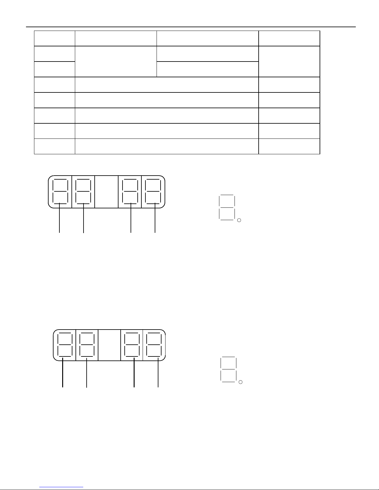
U-21 displays I/O signals status
Diagram 1 Diagram 2
In diagram 1, LED4 and LED5 stand for input signals status, and LED1 and LED2
stand for output signals status. In diagram 2 there shows the segment No. of each LED.
The description of led display please refer to《DS2 series servo drive user manual》。
U-22 displays I/O terminals status
Diagram 1 Diagram 2
In diagram 1, LED5 stands for input signals status, and LED2 stands for output signals
status. In diagram 2 there shows the segment No. of each LED.
0
1
2
3
5
4
6
7
0
1
2
3
5
4
6
7
LED1 LED2 LED4 LED5
LED1 LED2 LED4 LED5
Page 25
25
The description of led display please refer to DS2 series servo drive user manual.
4. Auxiliary Function
Use the operate panel to do application in auxiliary function mode.
Group No.
Content
F0-**
Check system information, display the system code and data
F1-**
Auxiliary run mode, display the auxiliary run command and result
F2-**
Set the motor code
F3-**
Check the alarm information, clear the alarm
F4-00
Reset parameters to default
F5-00
External communication monitoring
Check System Information
Press STATUS/ESC to switch to the auxiliary function mode. Set the group No. to 0 to
check system information. Press INC or DEC key to select different No., and press and hold
ENTER key to check current information. Press STATUS/ESC key to return.
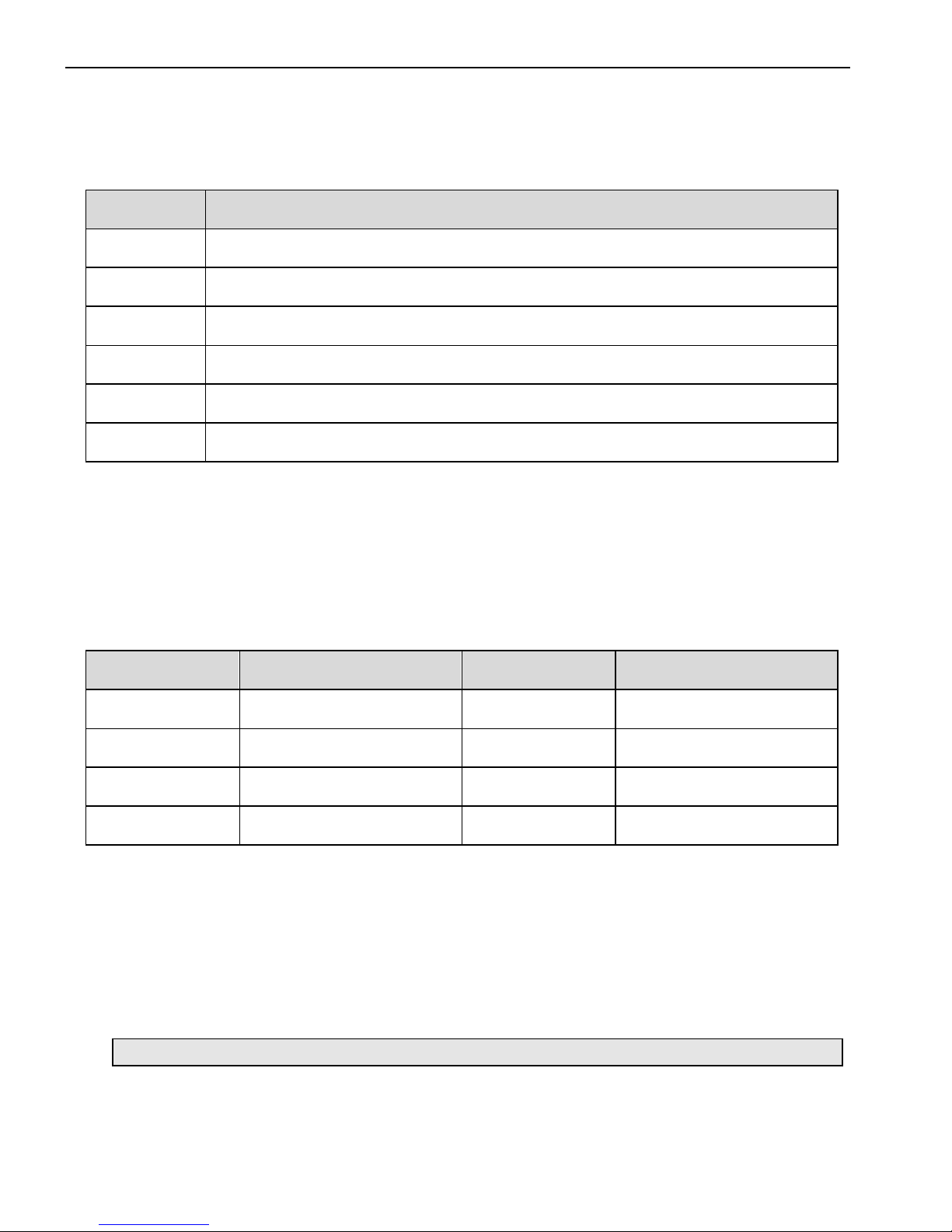
The following table describes the meaning of each No.:
Function No.
Description
Function No.
Description
F0-00
Motor Code
F0-01
Servo Series
F0-02
Servo Model
F0-03
Produce Date: Year
F0-04
Produce Date: Month
F0-05
Produce Date: Day
F0-06
Software Version
F0-07
Hardware Version
Auxiliary Run Mode
Press the STATUS/ESC key to select the auxiliary function mode. Set the group No. to
1. Press INC or DEC key to select different No., and press and hold ENTER key to use
current function. Press STATUS/ESC key to return.
(1)Jog (F1-00)
Make sure that the motor shaft is not connected to the machine before jogging!
Press ENTER to power on the motor (servo on). Press INC for forward jogging, press
DEC for reverse jogging. Press STATUS/ESC key to power off the motor (servo off), and
Page 26
26
press STATUS/ESC key again to return.
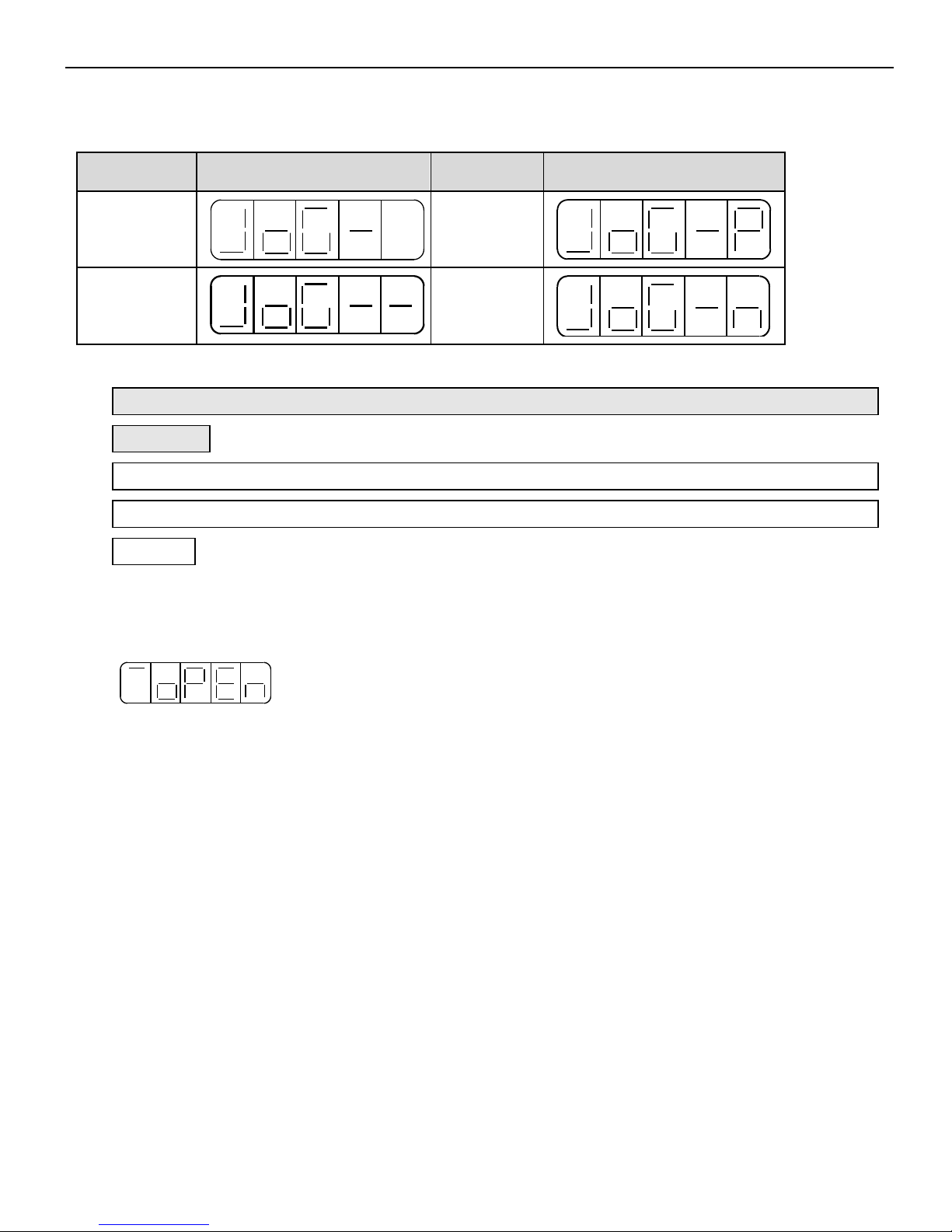
4 different states of jogging:
State
Panel Display
State
Panel Display
Idle
Forward
Jogging
Servo ON
Reverse
Jogging
(2)Trial Operation (F1-01)
Make sure that the motor shaft is not connected to the machine before trial
operation!
When servo drive is connected with non-original encoder line or power line, trial
operation must be run first to ensure that the encoder line or power line is connected
correctly.
Set the display value to 1, and press and hold ENTER key to enter trial operation mode.
The operate panel displays:
If correctly wired, the motor would rotate in 5 seconds in forward direction (fixed to
counter-clockwise), otherwise the motor would shock or vibrate, raising an alarm for worse.
In this case the power must be switched off immediately and check the wiring again.
Press STATUS/ESC key to return.
(3)Current Offset Auto-Adjustment (F1-02)
After the servo drive is updated to latest software version, or the motor does not revolve
smoothly for long time, the current offset auto-adjustment is recommended.
Select F1-02 and enter current offset auto-adjustment function, and the panel displays
“rEF”.
Press ENTER key to start current offset auto-adjustment, and the panel displays
blinking “rEF”.
Page 27

27
About 5 seconds later auto-adjustment is finished, and the panel displays “donE” to
inform that the function is already finished.
Press STATUS/ESC key to return.
(4)Speed command offset auto-adjustment (F1-03)
Select F1-03 and enter speed command offset auto-adjustment function, and the panel
displays “rEF_o”.
Press ENTER key to start speed command offset auto-adjustment, and the panel
displays blinking “rEF_o”.
About 1 second later, auto-adjustment is finished, and the panel displays “donE” to
inform that the function is already finished.
Press STATUS/ESC key to return.
(5)Torque command offset Auto-Adjustment (F1-04)
Select F1-04 and enter torque command offset auto-adjustment function, and the panel
displays “rEF_o”.
Press ENTER key to start torque command offset auto-adjustment, and the panel
displays blinking “rEF_o”.
About 1 second later, auto-adjustment is finished, and the panel displays “donE” to
inform that the function is already finished.
Press STATUS/ESC key to return.
(6)Forced Servo enables (F1-05)
0:Cancel forced servo enables
1:Forced servo enables
Change the motor type
Set the group No. to 2 in auxiliary function mode.
The servo drive can match multi-servo-motor with close power classes printed on the
nameplate of each motor. When user needs to change a motor, please refer to the Quick
Guide to ensure the motor match the driver.
The following steps are how to change motor type.
Page 28

28
(1)Press STATUS/ESC key to select Auxiliary Function mode.
(2)Press INC or DEC key to set group No. to 2, and press ENTER to confirm.
(3)Press and hold ENTER key to display current motor type.
(4)Press INC, DEC or ENTER key to show the motor type and press and hold
ENTER key to confirm.
(5)Repower on the servo drive to make this function effective.
Check Alarm Information
Set group No. to 3 in auxiliary function mode and enter checking alarm information
mode.
The following steps show how to check alarm information.
(1)Press STATUS/ESC key to select Auxiliary Function mode.
(2)Press INC or DEC key to set group No. to 3, and press ENTER key.
(3)Press INC, DEC or ENTER key to modify the alarm No.
(4)Press and hold ENTER key to display corresponding alarm information.
The descriptions of alarm information please refer to DS2 series servo drive user
manual.
Reset Parameters to Default
The following steps show how to reset parameters to default.
(1)Press STATUS/ESC key to select Auxiliary Function.
(2)Press INC or DEC key to set group No. to 4, and press ENTER key.
(3)Press and hold ENTER key, and the panel displays “0” and is blinking.
(4)Set the value to 1. Press and hold ENTER key to confirm.
(5)Repower on the drive and the parameters are all reset to default.
External monitoring
Select F5-00 in auxiliary function, the panel displays “C-OUT” which means external
monitoring mode, COM1 is effective, operate panel is ineffective. At this time user can
debug the servo via PC.
Press STATUS/ESC to return.
Page 29
29
5. Parameter Setting
Select or adjust the functions via parameter setting. The following steps show how to
change a parameter.
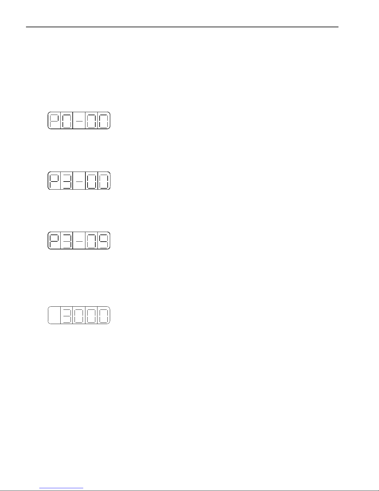
The example below shows how to change parameter P3-09 from 2000 to 3000.
(1)Press the STATUS/ESC key to select the parameter setting mode.
(2)At this time the second LED is blinking, and press INC or DEC key to set the group No.
to 3. Press ENTER key to confirm.
(3)At this time the last LED is blinking, and press INC or DEC key to set the member No.
to 9. Press and hold ENTER key to confirm.
(4)At this time the panel displays the value in P3-09, and the last decimal “0” is blinking.
Press ENTER to left shift the blinking decimal. Press INC, DEC or ENTER key to modify
the value to 3000, and press and hold ENTER to confirm.
The parameter in P3-09 in changed from 2000 to 3000.
Repeat steps 2 to 4 to change the parameter again.
(5)Press STATUS/ESC key to return.
6. Alarm
Alarm code will pop up (E-XXX) if there is error in servo. The alarm state is invisible
when there is no error in servo. Press ENTER to reset the alarm.
It is no need to reset the alarm when the servo is OFF because of error.
Notes: when there is alarm, please clear the alarm reasons, then reset the alarm.
Page 30
30
►► Parameter list
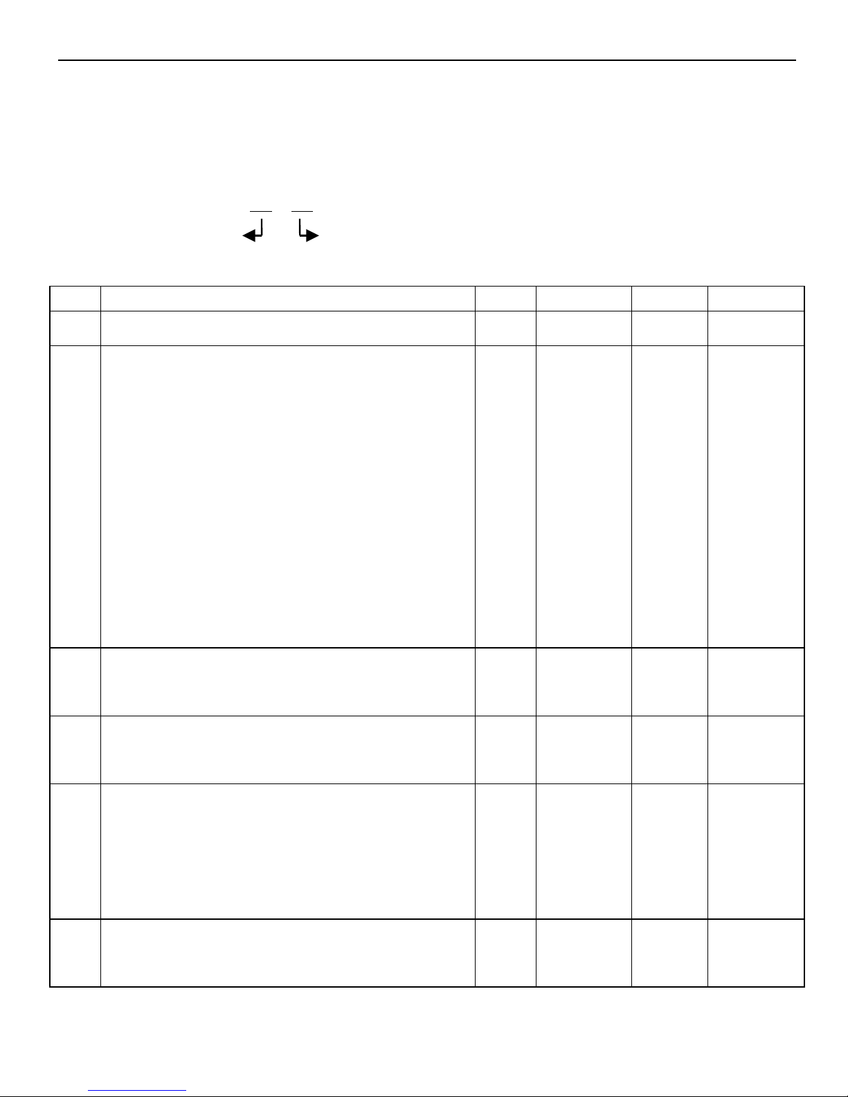
Effective time:○ means the parameter can be modified when the servo is OFF, and effective
when servo is ON.
Parameter:PX-XX=×× ××
PX-XX. H PX-XX.L
1. P0: function selection (Address:0000~00FF)
P0-
Function
Unit
Default
Range
Effective
00
Main mode
- 0 0
01
Submode 1
0: idle
1: torque (command)
2: torque (analog)
3: speed (command)
4: speed (analog)
5: position (internal)
6: position (pulse)
7: speed (pulse)
- 6 0~7
○
02
Submode 2
0~7: same as submode 1
- 0 0~7
○
03
Modbus station of serial port 2
- 1 1~
255
●
04
Parameter of serial port 2
-
n.2206
n.000
0~
n.220
9
●
05
Rotation direction selection
0:From the side view of motor load, CCW is
- 0 0、1
●
Page 31
31
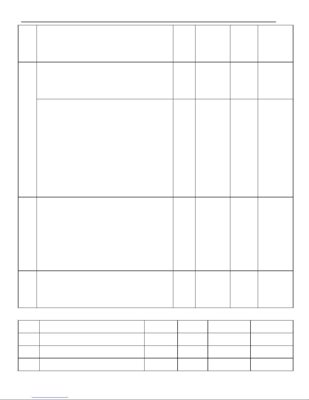
forward rotate
1:From the side view of motor load, CW is
forward rotate
06
06.L: stop mode when servo OFF or alarm.
DS2 series default is inertia stop. Keep the
inertia motion after stop.
- 2 0~2
●
06.H: over range (OT) stop mode
0~1: inertia stop. Keep inertia motion after
stop.
2: deceleration stop. Change to zero clamp
after stop. Torque: P4-06 urgent stop torque.
3: deceleration stop. Change to inertia
motion after stop. Torque: P4-06 urgent stop
torque.
- 2 0~3
●
07
T-REF distribution
0: undefined.
1: make T-REF as external torque limit input
2: undefined.
3: when P-CL, N-CL is ON, make T-REF as
external torque limit input.
- 0 0~3
○
08
V-REF distribution
0: 1: make V-REF as external speed limit input.
- 0 0、1
○
2. P1: control parameters (Address:0100~01FF)
P1-
Name
Unit
Default
Range
Effective
00
The gain of speed loop
1Hz
100
1~5000
√
01
Speed loop integral time
0.1ms
400
1~50000
√
02
The gain of position loop
1/s
100
1~2000
√
Page 32
32
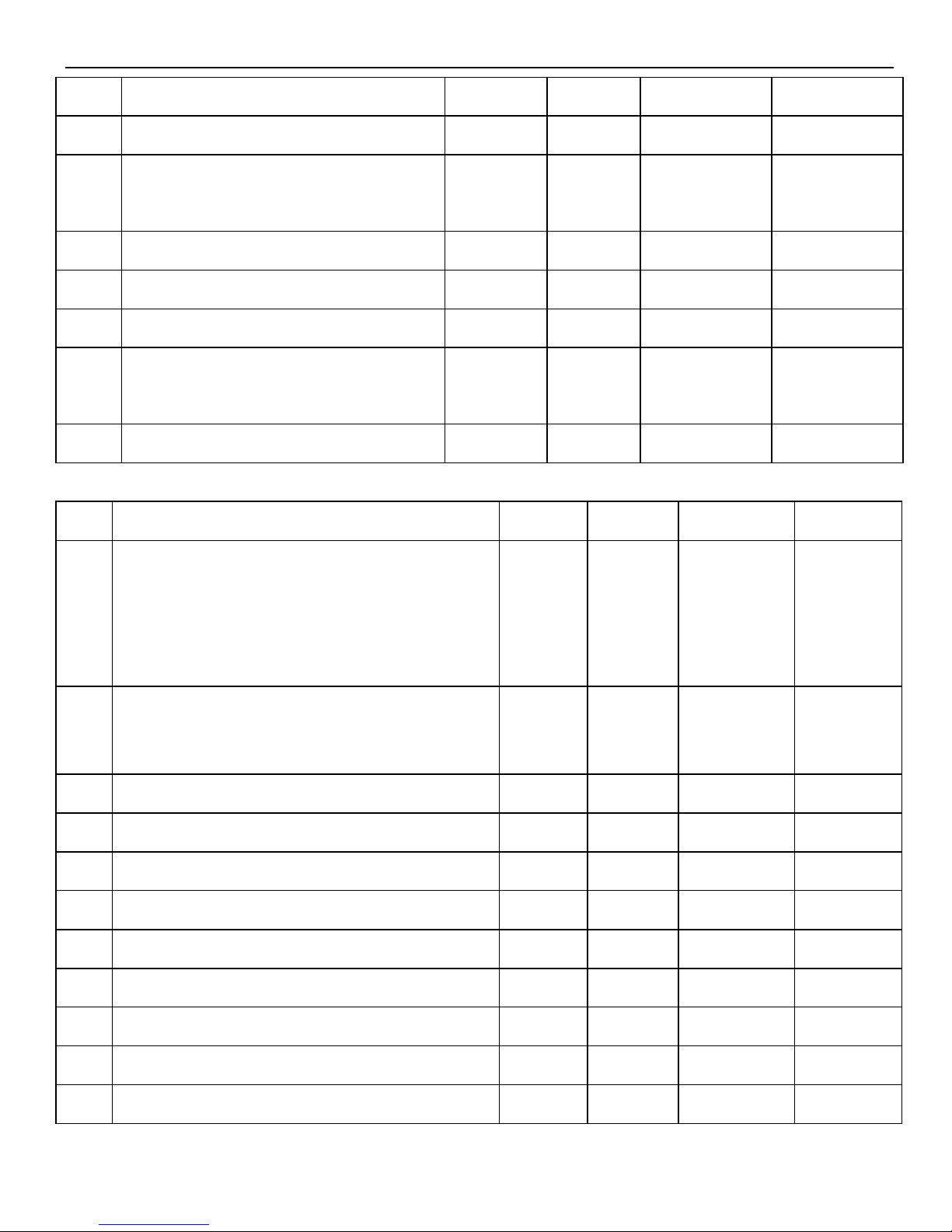
03
Reserved
04
The gain of second speed loop
1Hz
250
1~5000
√
05
Integral time of second speed
loop
0.1ms
10000
1~50000
√
06
The gain of second position loop
1/s
250
1~2000
√
07
Reserved
08
Reserved
09
The gain of position loop
feedforward
1%
0
0~100
√
10
Feedforward filter time
0.01ms
0
0~65535
√
3. P2: position control(0200~02FF)
P2-
Function
Unit
Default
Range
Effective
00
Command pulse state
0:Symbol+ Pulse train
1:AB phase pulse(90°phase, 4-time
mode)
2:Pulse+ direction
- 2 0,1,2
●
01
Position command filter selection
0:First order inertia filtering
1:smoothing filtering
- 0 0,1
●
02
Electronic gear ratio (molecular)
- 1 1~65535
√
03
Electronic gear ratio (denominator)
- 1 1~65535
√
04
Position command filter time
1ms
0
0~100
●
05
Reserved
06
Command pulse frequency at rated speed
100Hz
5000
1~10000
○
07
Speed command pulse filter time
0.1ms
20
0~1000
√
08
Reserved
09
Reserved
10
Internal position mode setting
-
n.0000
●
Page 33
33
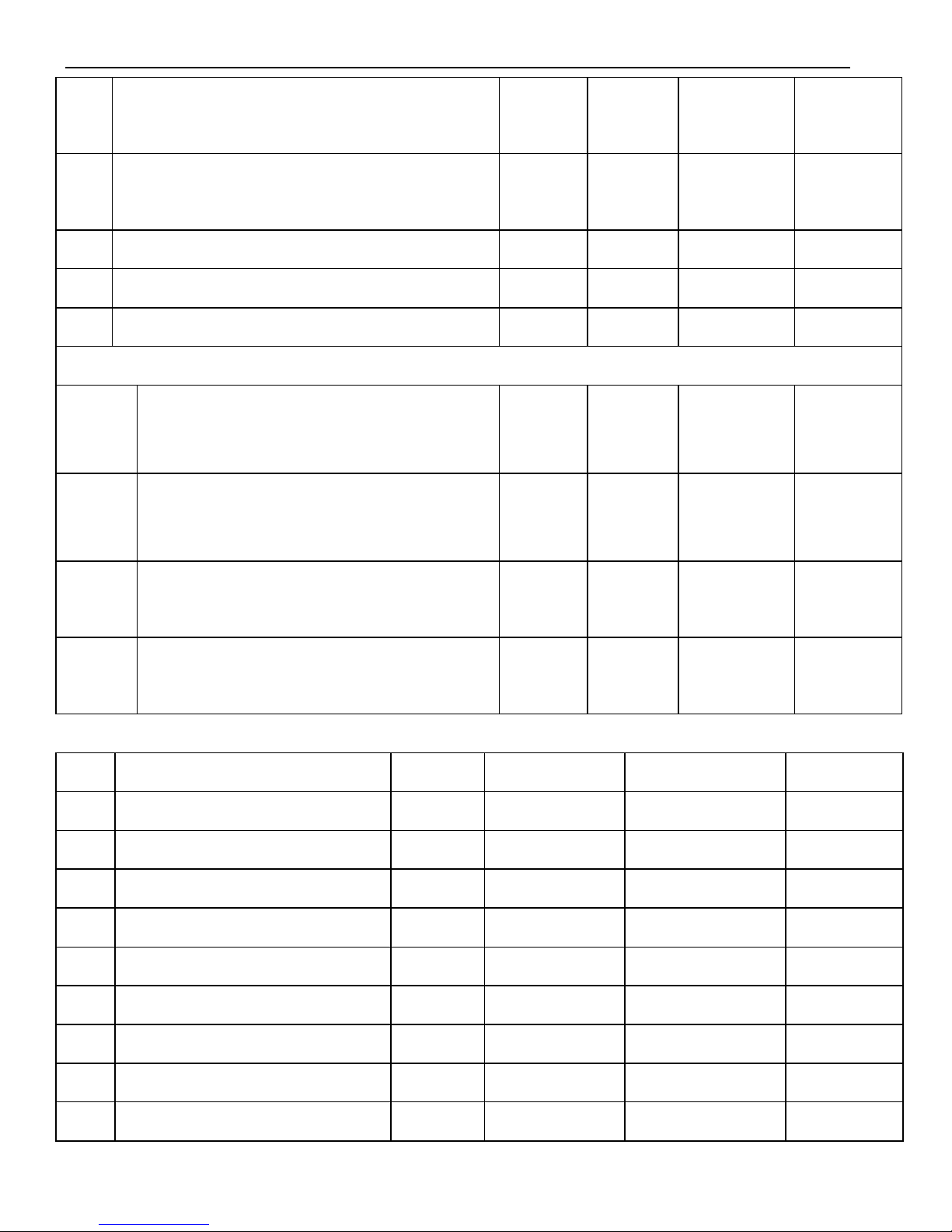
11
First segment pulse (low bit)
1 0 -9999~
+9999
○
12
First segment pulse (high bit)
1 0 -9999~
+9999
○
13
First segment speed
0.1rpm
0
0~50000
○
14
First segment adjustment time
1ms
0
0~65535
○
15
First segment command filter time
0.1ms
0
0~65535
○
P2-16~P2-90 are 2~16 segments parameter setting.
94.
xx□x
Find the original point
0: invalid
1: valid
- 0 0~1
●
94.
xxx□
The signal quantity pass the Z phase
signal at the direction of leaving the
limit switch
A
2
1~ F
(Hex)
●
95
The speed of closing the proximity
switch
0.1rpm
600
0~50000
○
96
The speed of leaving the proximity
switch
0.1rpm
100
0~50000
○
4. P3: speed control(0300~03FF)
P3-
Name
Unit
Default
Range
Effective
00
Analog value of rated speed
0.01V
1000
150~3000
○
01
Internal setting speed 1
rpm
100
-5000~+5000
√
02
Internal setting speed 2
rpm
200
-5000~+5000
√
03
Internal setting speed 3
rpm
300
-5000~+5000
√
04
JOG speed
rpm
100
0~1000
√
05
Soft start acceleration time
1ms
0
0~65535
○
06
Soft start deceleration time
1ms
0
0~65535
○
07
Speed command filter time
0.01ms
0
0~65535
○
08
Speed feedback filter time
0.01ms
20
0~65535
○
Page 34
34
09
Max speed limit (MAX
speed)
rpm
Different for
each type
0~5000
●
10
Speed command input dead
area voltage
0.01V
0
0~100
○
5. P4: torque control(0400~04FF)
P4-
Name
Unit
Default
Range
Effective
00
Analog value of rated torque
0.01V
1000
150~3000
○
01
Torque command filter time
0.01ms
0
0~65535
○
02
Forward torque limit
1%
300
0~300
√
03
Reverse torque limit
1%
300
0~300
√
04
Forward external torque limit
1%
100
0~300
√
05
Reverse external torque limit
1%
100
0~300
√
06
Urgent stop torque
1%
300
0~300
○
07
Internal speed limit when torque
controlling
rpm
2000
1~5000
√
08
Reserved
09
Internal torque command setting
1%
0
-300~300
√
10
Torque command input dead area
voltage
0.01V
0
0~100
○
6. P5: signal parameter setting(0500~05FF)
P5-
Name
Unit
Default
Range
Effective
00
Positioning finished width /COIN
Command
pulse
7
0~250
○
01
Zero clamp speed /ZCLAMP
rpm
10
0~300
○
02
Rotation checking speed /TGON
rpm
20
1~1000
○
03
Coincide speed checking signal
width /V-CMP
rpm
10
1~250
○
Page 35
35
04
Near output signal width /NEAR
Command
pulse
50
0~10000
○
05
Offset pulse limit value
256*
command
pulse
1000
0~65535
○
06
Servo OFF delay time (brake
command)
1ms
0
0~500
○
07
Brake command output speed
rpm
100
0~5000
○
08
Brake command wait time
1ms
500
10~1000
○
09
Input filter time
5ms
0
0~100
√
10
/S-ON servo signal
0000: signal is always ineffective
0001: input positive signal to SI1
0002: input positive signal to SI2
0003: input positive signal to SI3
0004: input positive signal to SI4
0005: input positive signal to SI5
0006: input positive signal to SI6
0010: signal is always effective
0011: input negative signal to SI1
0012: input negative signal to SI2
0013: input negative signal to SI3
0014: input negative signal to SI4
0015: input negative signal to SI5
0016: input negative signal to SI6
-
0001
0000-0016
●
11
/P-CON proportion action
command ditto
-
0000
0000-0016
●
12
/P-OT forward drive prohibition
-
0003
0000-0016
●
Page 36
36
ditto
13
/N-OT reverse drive prohibition
ditto
-
0004
0000-0016
●
14
/ALM-RST alarm reset
ditto
-
0002
0000-0016
●
15
/P-CL forward external torque
limit
ditto
-
0000
0000-0016
●
16
/N-CL reverse external torque limit
ditto
-
0000
0000-0016
●
17
/SPD-D internal speed selection
ditto
-
0000
0000-0016
●
18
/SPD-A internal speed selection
Same to above
-
0005
0000-0016
●
19
/SPD-B internal speed selection
ditto
-
0006
0000-0016
●
20
/C-SEL control mode selection
ditto
-
0000
0000-0016
●
21
/ZCLAMP zero clamp
ditto
-
0000
0000-0016
●
22
/INHIBIT command pulse
prohibition
ditto
0000
0000-0016
●
23
/G-SEL gain switch
ditto
-
0000
0000-0016
●
24
/CLR clear pulse offset
ditto
-
0000
0000-0016
●
Page 37
37
25
/CHGSTP step change signal
ditto
-
0000
0000-0016
●
26
Reserved
27
Reserved
28
/COIN positioning finished
0000: not output to the terminal
0001: output positive signal from
SO1
0002: output positive signal from
SO2
0003: output positive signal from
SO3
0011: output negative signal from
SO1
0012: output negative signal from
SO2
0013: output negative signal from
SO3
-
0001
0000-0013
●
29
/V-CMP speed coincide checking
ditto
-
0000
0000-0013
●
30
/TGON rotation checking
ditto
-
0000
0000-0013
●
31
/S-RDY ready
ditto
-
0003
0000-0013
●
32
/CLT torque limit
ditto
-
0000
0000-0013
●
33
/VLT speed limit checking
ditto
-
0000
0000-0013
●
Page 38
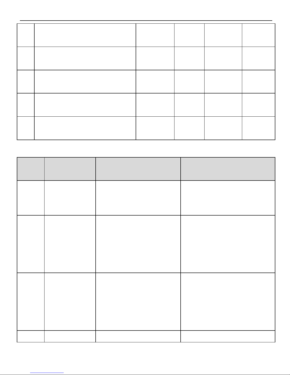
38
34
/BK brake lock
ditto
-
0000
0000-0013
●
35
/WARN warn
ditto
-
0000
0000-0013
●
36
/NEAR near
ditto
-
0000
0000-0013
●
37
/ALM alarm
ditto
-
0002
0000-0013
●
38
/Z encoder Z signal
ditto
-
0000
0000-0013
●
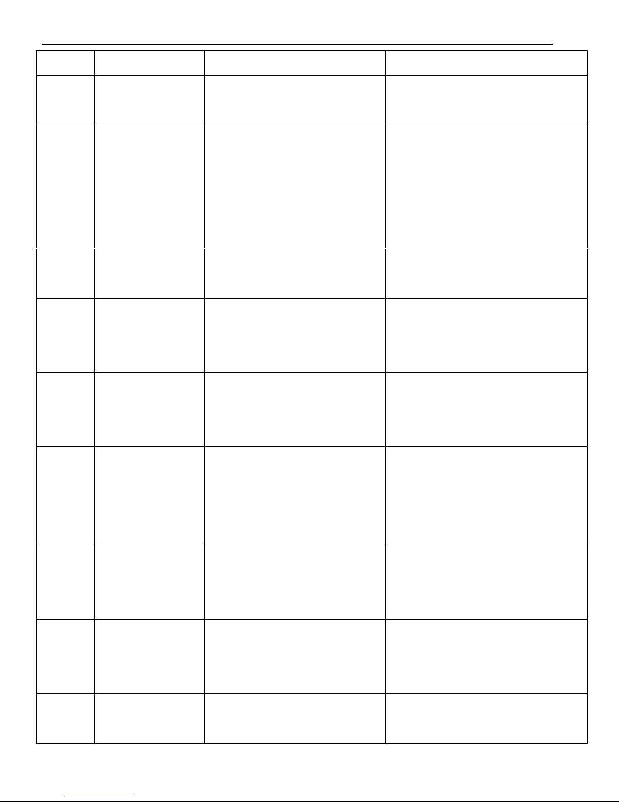
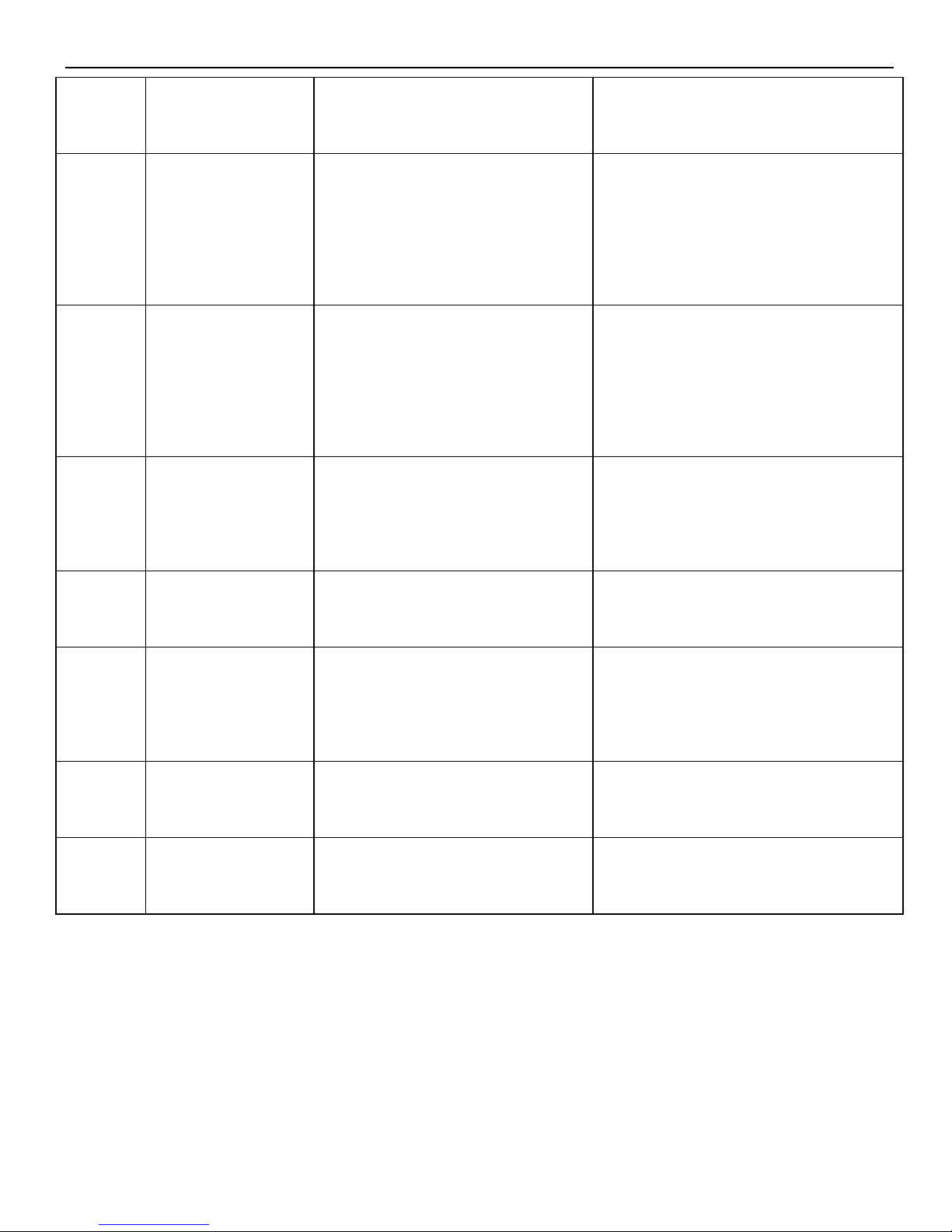
►► Alarm Information
Alarm
Code
Description
Reason
Solution
E-001
Program
damage
program self-test failed
Re-download the program or
contact XINJE or an authorized
distributor
E-002
Parameter
damage
Parameter self-test failed
Restart the drive to reset the
parameters. If it occurs for
many times please contact
XINJE or an authorized
distributor
E-003
Bus
over-voltage
Power grid is over voltage or
need a regenerative resistor;
the regenerative resistor
damage or its value is too
large
Check the power grid; connect
and check the regenerative
resistor
E-004
Bus under
Power grid is under voltage
Check the power grid
Page 39
39
voltage
E-005
Regenerative
resistor error
Regenerative resistor is
ineffective
Check the connection of
regenerative resistor
E-006
Module over
temperature
Run with large load for long
time
Reduce the load, and enhance
the cooling system, or check if
the fan is revolving when motor
is ON; cool down the ambient
temperature
E-007
Over current
UVW of drive is short
circuit or the motor is error
Replace the damaged motor;
check the UVW wiring.
E-008
Over speed
Motor speed is too fast,
motor UVW connection is
error
Check if there is other device
that make motor revolve too
fast; check the UVW wiring.
E-009
Analog input
error
Input voltage error when
2-channe analog zero
calibrating
Input correct voltage when zero
calibration for analog
E-010
Position offset
too large
The difference between set
position and actual position
exceeds the limit value
Check if the motor stalled,
decrease the set position speed,
increase offset pulse limit value
P5-05
E-011
Motor UVW is
short circuit
External is short circuit
when fist self-test
Check the UVW wiring of
motor, or replace the damaged
motor
E-012
Motor UVW
current error
Current collection circuit
error
Check the UVW wiring of
motor, or replace the damaged
drive
E-013
Encoder UVW
wire break
Encoder wiring error,
encoder broken, encoder is
Check the wiring of encoder,
and re-connect the encoder after
Page 40
40
not connected
power-off, or replace the
damaged encoder
E-014
Encoder ABZ
wire break
Encoder wiring error,
encoder broken, encoder is
not connected
Check the wiring of encoder,
and re-connect the encoder after
power-off, or replace the
damaged encoder
E-015
Speed changes
too fast
(encoder
feedback error)
The encoder wiring is error,
or the encoder has
interference
Check the wiring of encoder, or
add shield layer for the encoder
wire
E-016
Overload
Run overload for long time
Reduce the overload running
time, change a motor with larger
rated power
E-017
Power off when
running
Bus voltage is too low when
running
Re-power on after the bus
voltage is normal
E-018
Erase parameter
error
Voltage is too low when
power on, cannot erase the
parameter
Check the power supply and
re-power on
E-031
Motor code
error
Motor code cannot match to
drive type
Set the motor code in F2-00
again
E-032
Initialization
error
System chip is damaged
Contact XINJE or an authorized
distributor
►►Debug steps
b) Please check the products before power on, make sure the devices are not
significant damage.
c) Connect the cables correctly. Connect U, V, W one-to-one, don’t cross them.
d) Power on, panel display: bb;
Page 41
41
e) Enter F2-00,set the correct motor code.
f) After power on again,proceed to current Offset Auto-Adjustment,please refer to
auxiliary run mode;
g) Set F1-01=1, check if the motor can work normally. If yes, enter F1-00. If not,
check the cables.
h) Enter F1-00 and proceed to jog test-running, if work normally, connect to motor.
i) Before start the devices, set the parameters of servo according to actual
application, and adjust in real-time.
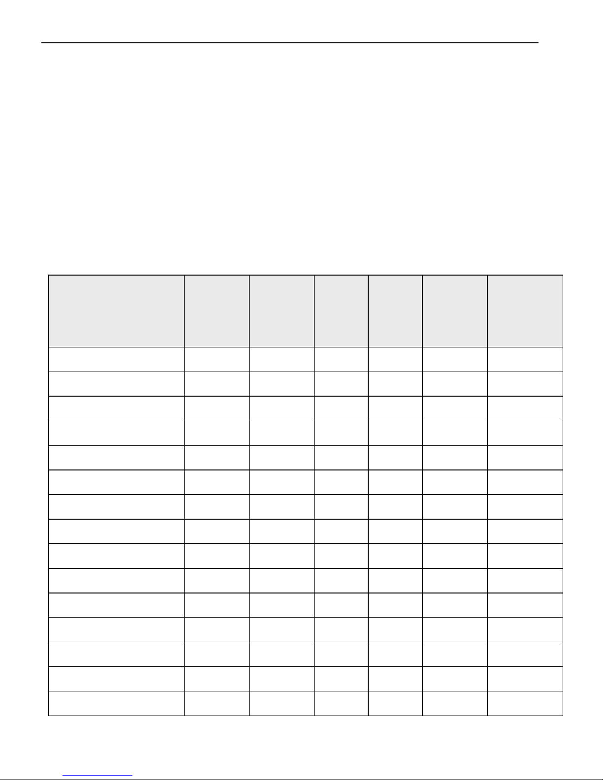
►►Motor code
Motor Type
Capacity
KW
Torque
Nm
Rotate
speed
RPM
Current
A
Overload
Motor code
MS-60ST-M00630
0.2
0.637
3000
1.8
3
1003
MS-60ST-M01330
0.4
1.27
3000
2.5
3
0004
MS-80ST-M02430
0.75
2.39
3000
3.0
3
0011
MS-90ST-M02430
0.75
2.4
3000
3.0
3
0021
MS-110ST-M04030
1.2
4
3000
5.0
3
0031
MS-110ST-M05030
1.5
5
3000
6.0
3
0032
MS-130ST-M06025
1.5
6
2500
6.0
3
0042
MS-130ST-M10015
1.5
10
1500
6.0
2.5
0044
MS-130ST-M07725
2.0
7.7
2500
7.5
3
0043
MS-130ST-M15015
2.3
15
1500
9.5
2
0046
MS-180ST-M19015
3.0
19
1500
12.0
2.5
0052
MS-180ST-M21520
4.5
21.5
2000
9.5
2.5
0150
MS-180ST-M27015
4.3
27
1500
10
2.5
0151
MS-180ST-M35015
5.5
35
1500
12 2 0152
MS-180ST-M48015
7.5
48
1500
20 2 0153
Page 42
42
►► Suitable motor code for each servo drive
Servo drive
Motor code
DS2-20P2-AS
1003
DS2-20P4/-A/-AS
0004
DS2-20P7/-A/-AS
0011(Default setting)
0021
DS2-21P5/-A/-B
0031
0032
0042
0044(Default setting)
DS2-22P3-A
0043
0046(Default setting)
DS2-23P0-A
0052(Default setting)
DS2-45P5-A
0150
0151
0152(Default setting)
DS2-47P5-A
0153(Default setting)
Page 43

43
WUXI XINJE ELECTRIC CO., LTD.
4th Floor, Building 7th, No.100 Dicui
Rd, Wuxi, China
Tel: 86-0510-85134139
Fax: 86-0510-85111290
www.xinje.com
Email: [email protected]
 Loading...