


DS2 series servo drive
User manual
WUXI XINJE ELECTRIC CO., LTD.
Serial No. SC2 00 20140320 1.0

All copyrights reserved by WUXI XINJE ELECTRIC CO., LTD.
Any copying, transferring or any other usage is pro hibited. Otherwise Xinje will have the right to
pursue legal responsibilities. All rights including patent and pemission of modules and designs are
reserved.
January, 2010

a
The following defines the symbols used in this manual to indicate varying degrees of
safety precautions and to identify the corresponding level of hazard inherent to each.
Failure to follow precautions provided in this manual can result in serious, possibly even
fatal, injury, and/or damage to the persons, products, or related equipment and systems.
CAUTION
Indicates a potentially hazardous situation, which, if not heeded,
could result in death or serious injury
WARNING
Indicates a potentially hazardous situation, which, if not avoided,
may result in minor or moderate injury.
Checking Products upon Delivery
CAUTION
1. DO NOT install any drive which is damaged, lack of accessories or not the same with
the model ordered.
Doing so may result in electric shock.
Installation
WARNING
1. Cut off external power supply before installation.
Not doing so may result in electric shock.
CAUTION
1. Always use the servomotor and servo amplifier in one of the specified combinations.
Never use the products in an environment subject to water, corrosive gases,
inflammable gases, or combustibles.
Doing so may result in electric shock, fire or malfunction.
2. DO NOT touch any metallic part.
Doing so may result in malfunction.
Wiring
WARNING
1. Cut off external power supply before wiring.
Not doing so may result in electric shock.
2. Connect AC power supply to the corresponding terminals.
Faulty wiring may result in fire.
Be sure to review this section carefully before use this product. In precondition of
security, wire the product correctly.
Safety Precautions
b
CAUTION
1. Do not connect a three-phase power supply to the U, V, or W output terminals.
Doing so may result in injury or fire.
2. Use 2mm2 wire to grounding the groud terminals.
Not doing so may result in electric shock.
3. Securely fasten the power supply terminal screws and motor output terminal screws.
Not doing so may result in fire.
Operation
WARNING
1. Never touch any rotating motor parts while the motor is running.
Doing so may result in injury.
2. DO NOT touch the inside the drive.
Doing so may result in electric shock.
3. Do not remove the panel cover while the power is ON.
Doing so may result in electric shock.
4. Do not touch terminals for five minutes after the power has been turned OFF.
Residual voltage may cause electric shock.
CAUTION
1. Conduct trial operation on the servomotor alone with the motor shaft disconnected from
machine to avoid any unexpected accidents.
Not doing so may result in injury.
2. Before starting operation with a machine connected, change the settings to match the
parameters of the machine.
Starting operation without matching the proper settings may cause the machine to run
out of control or malfunction.
3. Before starting operation with a machine connected, make sure that an emergency stop
can be applied at any time.
Not doing so may result in injury.
4. Do not touch the heat sinks during operation.
Not doing so may result in burns due to high temperatures.
5. Do not attempt to change wiring while the power is ON.
Doing so may result in electric shock or injury

i
Catalog
Preface .................................................................................................................................. I
1 Checking Product and Part Names ................................................................................... 2
1-1.Checking Products on Delivery ......................................................................... 2
1-2.Product appearance and name rule ..................................................................... 2
1-3.Adaptation table of servo drive and motor ......................................................... 5
2 Installations ...................................................................................................................... 6
2-1.Servomotor ......................................................................................................... 6
2-1-1.Storage Temperature ............................................................................... 6
2-1-2.Installation Site ....................................................................................... 6
2-1-3.Concentricity ........................................................................................... 6
2-1-4.Orientation .............................................................................................. 7
2-1-5.Handling Oil and Water .......................................................................... 7
2-1-6.Cable Stress ............................................................................................ 7
2-2.Servo Drive ........................................................................................................ 7
2-2-1.Storage Conditions .................................................................................. 7
2-2-2.Installation Site ....................................................................................... 7
2-2-3.Orientation .............................................................................................. 8
2-2-4.Installation .............................................................................................. 8
3 Wiring ............................................................................................................................. 10
3-1.Main Circuit Wiring ......................................................................................... 10
3-1-1.The terminal arrangement ..................................................................... 10
3-1-2. Main circuit terminals ............................................................................. 11
3-1-3.Winding Terminals on Servo motor ..................................................... 13
3-1-4.CN0, CN1, CN2 terminals .................................................................... 13
3-1-5. Communication port ............................................................................... 15
3-2.Signal terminals ................................................................................................ 16
3-2-1. Pulse signal ............................................................................................. 16
3-2-2.SI input signal ....................................................................................... 17
3-2-3. Analog input circuit ................................................................................ 18
3-2-4. Output signal ........................................................................................... 18
3-2-5. Encoder feedback signal ......................................................................... 19
3-3. Standard wiring example ................................................................................... 19
3-3-1.Position Control Mode .......................................................................... 19
3-4.Regenerative Resistor ...................................................................................... 23
4 Use the operate panel ..................................................................................................... 24
4-1.Basic Operation ................................................................................................ 24
4-1-1. Functions of operate panel ...................................................................... 24
4-1-2. Basic Mode Switching ............................................................................ 24
4-2.Running status mode ........................................................................................ 25
4-3.Monitoring Mode ............................................................................................. 26
4-4.Auxiliary Function ........................................................................................... 28
4-4-1.F0-XX ................................................................................................... 28
4-4-2. F1-XX ..................................................................................................... 28
4-4-3. Change the motor type (F2-00) ............................................................... 29
4-4-4.Check Alarm Information (F3-XX) ...................................................... 30

ii
4-4-5.Reset Parameters to Default (F4-XX) ................................................... 30
4-4-6. External monitoring (F5-XX) ................................................................. 30
4-5.Alarm (E-XX) .................................................................................................. 30
4-6.Example ........................................................................................................... 30
5 Run the servo system ...................................................................................................... 32
5-1.Control mode selection .................................................................................... 32
5-2.Basic function setting ....................................................................................... 32
5-2-1. Servo ON setting ..................................................................................... 33
5-2-2. Switch the motor rotate direction ........................................................... 33
5-2-3. Motor stop mode when use overtravel signal ......................................... 33
5-2-4. Overtravel Limit (P-OT & N-OT) .......................................................... 34
5-2-5. Power-off Brake (BK) ............................................................................ 35
5-2-6. Alarm output ........................................................................................... 36
5-2-7. Running time .......................................................................................... 37
5-2-8. Torque over-limit .................................................................................... 37
5-3.Position mode (external pulse command) ........................................................ 37
5-3-1. Control mode selection ........................................................................... 38
5-3-2. Pulse command ....................................................................................... 38
5-3-3. Electronic gear ratio ................................................................................ 39
5-3-4. Position command filter .......................................................................... 40
5-3-5. Pulse error clear (/CLR) .......................................................................... 41
5-3-6. Positioning complete (/COIN) ................................................................ 41
5-3-7. Positioning near (/NEAR) ....................................................................... 42
5-3-8. Command pulse prohibition (/INHIBIT) ................................................ 42
5-4.Position mode (internal position mode) ........................................................... 43
5-4-1. Control mode selection ........................................................................... 43
5-4-2. Internal position mode ............................................................................ 43
5-4-3. Position parameters from segment 1 to 16.............................................. 46
5-4-4. Change step (/CHGSTP) ......................................................................... 46
5-4-5. Pause current signal (/INHIBIT) ............................................................ 46
5-4-6. Skip current signal (/ZCLAMP) ............................................................. 47
5-4-7. Reference origin ...................................................................................... 47
5-4-8. Set segment through communication ...................................................... 49
5-5.Speed control (analog voltage command) ........................................................ 49
5-5-1. Control mode selection ........................................................................... 49
5-5-2. Analog value of rated speed ................................................................... 50
5-5-3. Speed command offset auto-adjustment (F1-03) .................................... 50
5-5-4. Proportion action command (/P-CON) ................................................... 50
5-5-5. Zero clamp (/ZCLAMP) ......................................................................... 50
5-5-6. Speed coincidence checking (/V-CMP) .................................................. 51
5-5-7. Torque limit ............................................................................................ 51
5-5-7-1. Internal torque limit (output torque max value limit) .......................... 51
5-5-7-2. External torque limit (via input signal) ............................................... 51
5-5-7-3. External torque limit (via analog voltage command) .......................... 52
5-5-7-4. External torque limit (via external input + analog voltage) ................ 52
5-5-7-5. Output torque up to limit value signal ................................................. 53
5-5-8. Soft start .................................................................................................. 53
5-5-9. Filter ........................................................................................................ 54
5-5-10. Speed command input dead voltage ..................................................... 54
5-6.Speed control (internal speed) .......................................................................... 54
5-6-1. Control mode selection ........................................................................... 55

iii
5-6-2. Internal speed setting .............................................................................. 55
5-6-3. Input signal setting .................................................................................. 56
5-7.Speed control (pulse frequency command) ...................................................... 57
5-7-1. Control mode selection ........................................................................... 57
5-7-2. Pulse frequency command ...................................................................... 57
5-7-3. Command pulse frequency at rated speed .............................................. 57
5-7-4. Speed command pulse filter time............................................................ 58
5-8.Torque control (analog voltage command) ...................................................... 58
5-8-1. Control mode selection ........................................................................... 58
5-8-2. The analog value of rated torque ............................................................ 58
5-8-3. Torque command offset autoadjustment (F1-04) ................................... 59
5-8-4. Torque command filter time ................................................................... 59
5-8-5. Torque limit ............................................................................................ 59
5-8-5-1. Internal speed limit .............................................................................. 59
5-8-5-2. External speed limit ............................................................................. 59
5-8-5-3. Speed up to limit value output ............................................................. 60
5-8-6. Torque command input dead area voltage .............................................. 60
5-9.Torque control (internal setting) ...................................................................... 60
5-9-1. Control mode selection ........................................................................... 60
5-9-2. Internal torque command ........................................................................ 60
5-10.Switch the control mode ................................................................................ 61
5-11.Other output signals ....................................................................................... 61
5-11-1. /ALM and /ALM-RST .......................................................................... 61
5-11-2. /WARN ................................................................................................. 61
5-11-3. Rotation checking (/TGON) ................................................................. 61
5-11-4. Servo ready (/S-RDY) .......................................................................... 62
5-11-5. Encoder Z phase output (/Z) ................................................................. 62
5-11-6. AB phase feedback signal of encoder ................................................... 62
5-12. I/O signal distribution ...................................................................................... 63
5-12-1. Input signal distribution ........................................................................ 63
5-12-2. Default setting of input terminal ........................................................... 64
5-12-3. Output terminal distribution ................................................................. 64
5-12-4. Default setting of output terminal ......................................................... 64
6 Servo gain adjustment .................................................................................................... 65
6-1.Gain setting of speed loop ................................................................................ 65
6-2.Gain setting of position loop ............................................................................ 65
6-3.The experience of parameter adjustment ......................................................... 66
6-4.Proportion action command (P-CON) ............................................................. 66
6-5.Gain switch (G-SEL)........................................................................................ 67
7 Specification and dimension .......................................................................................... 68
7-1.Servo motor ...................................................................................................... 68
7-1-1.Servo motor specification ..................................................................... 68
7-1-2.Torque-Speed Feature ........................................................................... 71
7-1-3.Servo motor dimensions ....................................................................... 72
7-2.Servo drives ...................................................................................................... 76
7-2-1.General specification ............................................................................ 76
7-2-2.Performance specification .................................................................... 76
7-2-3.Servo drive dimensions ......................................................................... 77
8 Alarm Information .......................................................................................................... 80
Appendix 1 Parameter list ................................................................................................. 82

iv
Appendix 2 Application .................................................................................................... 89

Preface
I
Preface
Constitution of This Manual
This manual is divided into 7 chapters.
1. Checking Product and Part Names
This chapter describes the procedure for checking products upon delivery as well as names
for product parts.
2. Installation
This chapter describes precautions for servomotor and servo drive installation.
3. Wiring
This chapter describes the procedure used to connect DS2 Series products to peripheral
devices and gives typical examples of main circuit wiring as well as I/O signal
connections.
4. Parameter Settings and Functions
This chapter describes the procedure for setting and applying parameters.
5. Use Digital Panel
This chapter describes the basic operation of the digital panel and the features it offers.
6. Ratings and Characteristics
This chapter provides the ratings, torque-speed characteristics diagrams, and dimensional
drawings of the DS2 series servo drives and MS series servomotors.
7. Alarm Information
This chapter describes the alarm information of DS2 series servo drives.
Intended User
This manual is intended for the following users.
Those designing DS2 Series servodrive systems.
Those installing or wiring DS2 Series servodrives.
Those performing trial operation or adjustments of DS2 Series servodrives.
Those maintaining or inspecting DS2 Series servodrives.
How to AcquireThis Manual
1.Electrical Manual
(1) Log on Xinje official website www.xinje.com to download.
(2) Acquire this manual on a CD from an authorized distributor.
This chapter describes the constitution of this manual, the intended user, and how to
acquire this manual.
Preface
2
1 Checking Product and Part Names
1-1.Checking Products on Delivery
Use the following checklist when products are delivered.
Items
Comments
Are the delivered products the ones
that were ordered?
Check the model numbers marked on the nameplates of the
servomotor and servo drive.
Does the servomotor shaft rotate
smoothly?
The servomotor shaft is normal if it can be turned smoothly
by hand. Servomotors with brakes, however, cannot be
turned manually.
Is there any damage?
Check the overall appearance, and check for damage or
scratches that may have occurred during shipping.
Are there any loose screws?
Check screws for looseness using a screwdrive.
Is the motor code the same with the
code in drive?
Check the motor code marked on the nameplates of the
servomotor and the parameter F0-00 on the servo drive.
If any of the above is faulty or incorrect, contact Xinje or an authorized distributor.
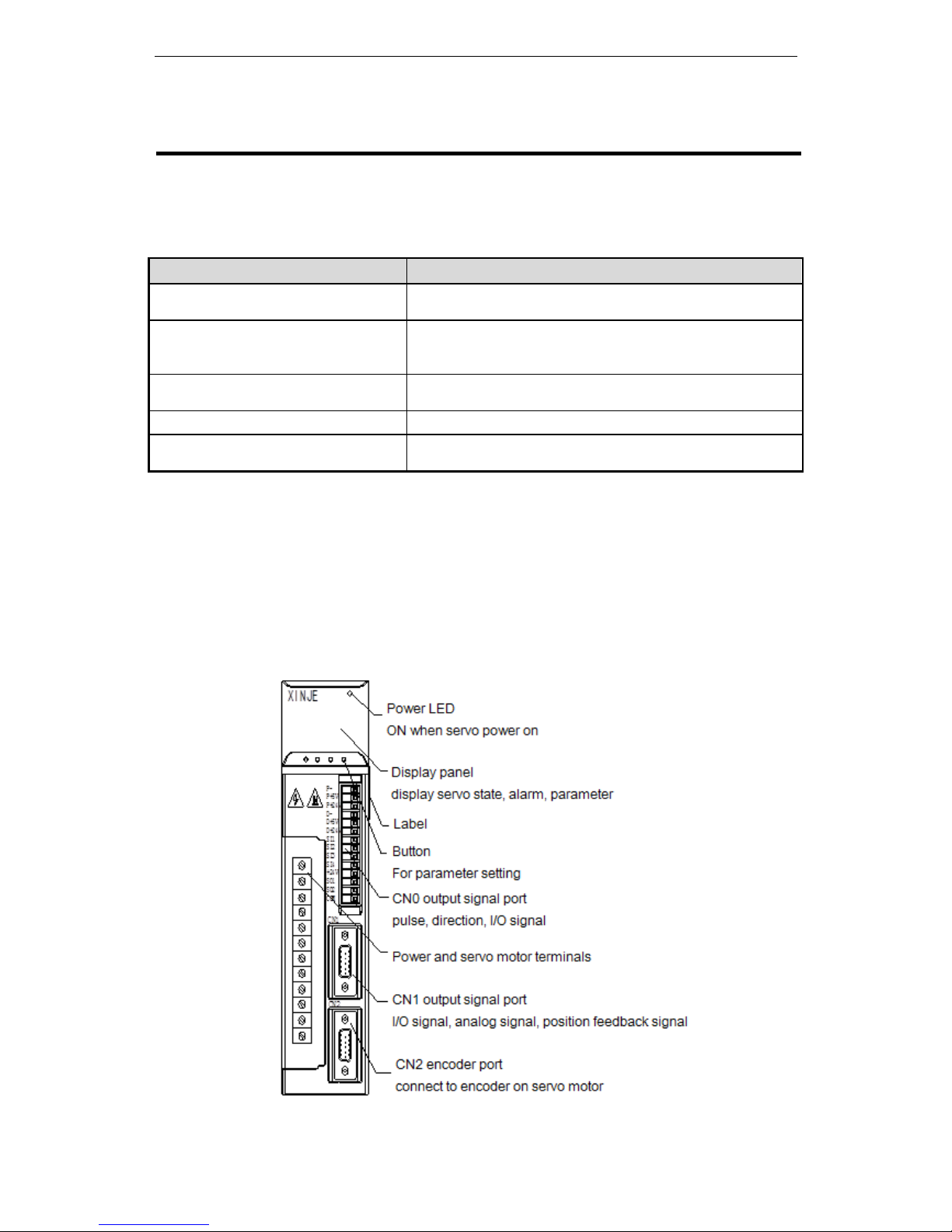
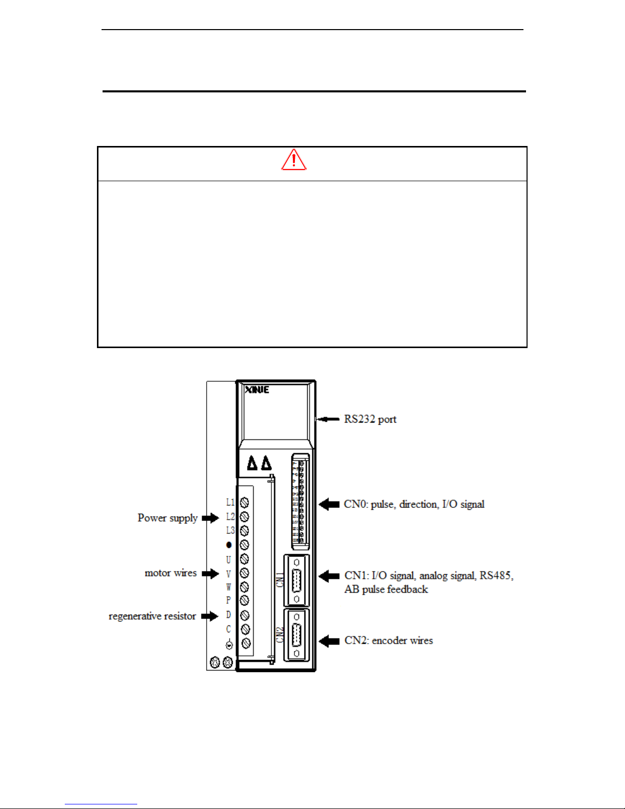
1-2.Product appearance and name rule
DS2-2□P□-AS/AS6 DS2-20P4-BS/BS6 DS2-20P7-BSW/BSW6 DS2-21P5-AS2
DS2-4□P□-AS/AS6
(1) Appearance and nameplate
3
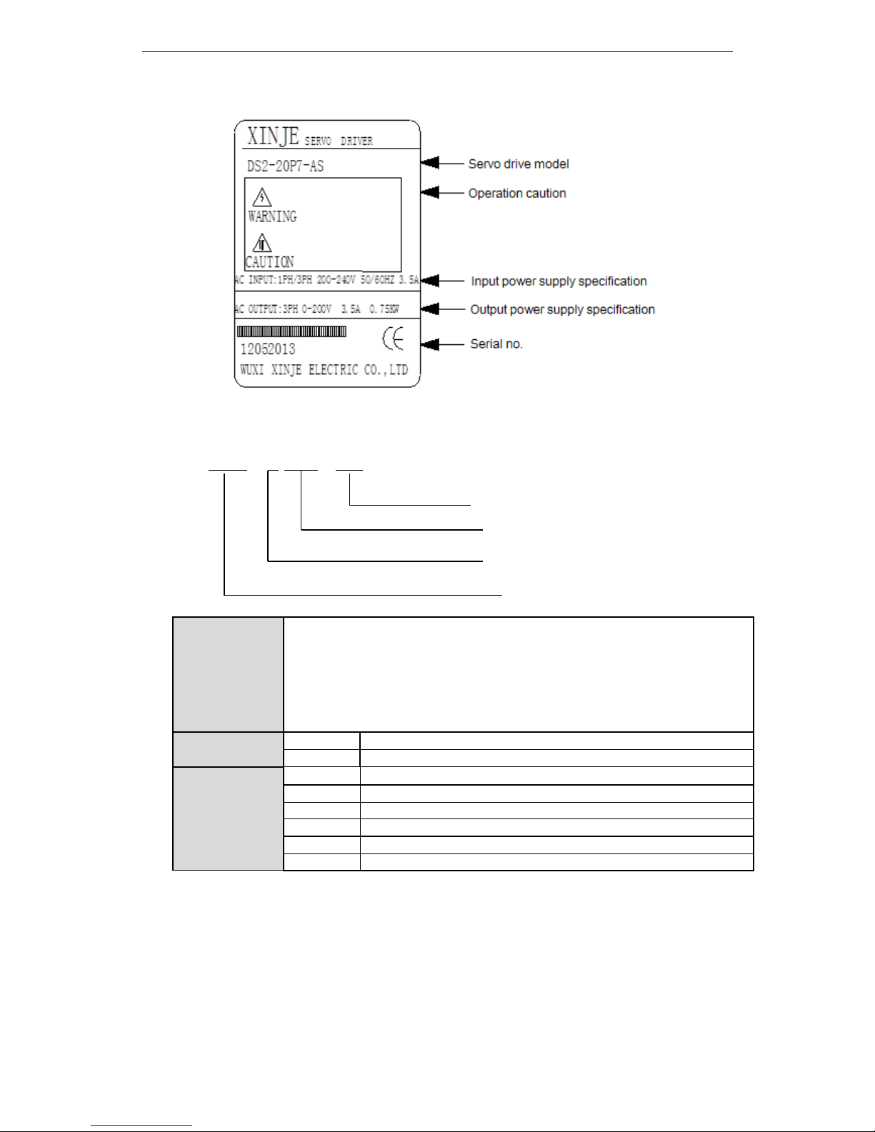
Servo drive nameplate
(2) Naming rule
DS2 – 2 1P5 - AS
configuration
AS series (differential mode encoder feedback)
AS6 series (differential mode encoder feedback, support AB phase pulse input)
AS2 series (simple model)
BS series (no encoder feedback)
BS6 series (no encoder feedback, support AB phase pulse input)
BSW series (no encoder feedback)
BSW6 series (no encoder feedback, support AB phase pulse input)
Voltage level
2
220V
4
380V
Suitable motor
capacity
0P2
0.2KW
0P4
0.4KW
0P7
0.75KW
1P5
1.5KW
2P3
2.3KW
3P0
3.0KW
Configure type
Series name
Suitable motor capacity
Voltage level
4
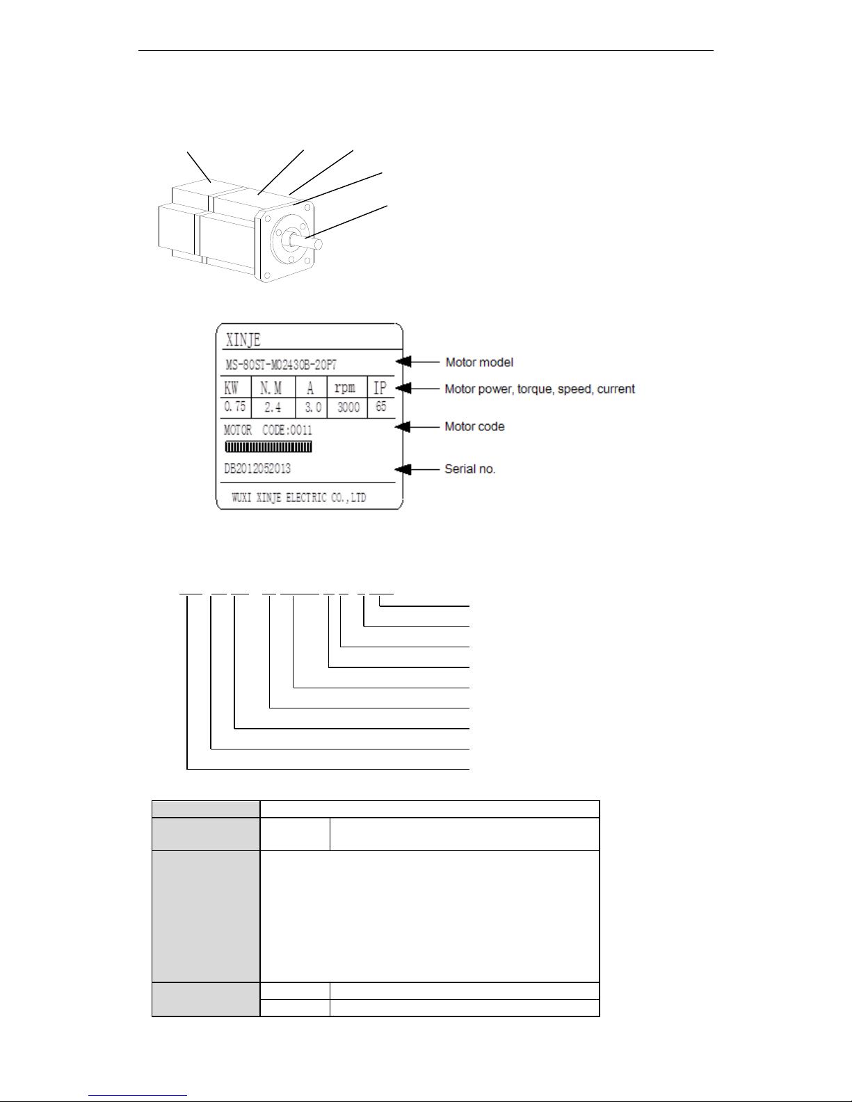
Servo motor
(1) Appearance and nameplate
Motor label
(2) Naming rule
MS -80 ST - M 02430 A Z- 2 0P7
Capacity
Rated Voltage
Power-loss brake
Shaft Specifications
Performance Specifications
Feedback Component
Sinewave-drive Motors
Base Size
Motor Series Name
Base number
60, 80, 90, 110, 130, 180
Feedback
component no.
M
Optical pulse encoder
Performance
parameter no.
First 3 bits mean rated torque, last 2 bits mean rated speed
Such as: 00630: rated torque 0.6N.m, rated speed 3000rpm
06025: rated torque 6.0N.m, rated speed 2500rpm
19015: rated torque 19.0N.m, rated speed 1500rpm
Shaft spec
A
No bond
B
With bond
Encoder part
Frame
Flange
Output (transmission) shaft
Motor label

5
Power-loss
brake
Vacant
No
Z
With power-off brake
Voltage level
2
220V
4
380V
Power
Such as: 0P4: 0.4kW
0P7: 0.75kW
1P5: 1.5KW
2P3: 2.3KW
1-3.Adaptation table of servo drive and motor
Servo drive
Servo motor
Motor code
Voltage level
DS2-20P2-AS/AS6
MS-60ST-M00630-20P2
1003
Single phase/ 3
phase 220V
DS2-20P4-AS/AS6
DS2-20P4-BS/BS6
MS-60ST-M01330-20P4
1004(0004)
DS2-20P7-AS/AS6
DS2-20P7-BSW/BSW6
MS-80ST-M02430-20P7
1011 (0011)
MS-80ST-M03520-20P7
0012
MS-90ST-M02430-20P7
0021
DS2-21P5-AS/AS6
DS2-21P5-AS2
MS-110ST-M04030-21P2
0031
3 phase 220V
MS-110ST-M05030-21P5
0032
MS-130ST-M06025-21P5
1042 (0042)
MS-130ST-M10015-21P5
0044
DS2-22P3-AS/AS6
MS-130ST-M07725-22P0
0043
3 phase 220V
MS-130ST-M15015-22P3
0046
DS2-41P5-AS/AS6
MS-110ST-M04030-41P2
0131
3 phase 380V
MS-110ST-M05030-41P5
0132
MS-130ST-M06025-41P5
0142
MS-130ST-M10015-41P5
0144
DS2-43P0-AS/AS6
MS-130ST-M10030-43P0
1148
MS-180ST-M19015-43P0
0156
MS-180ST-M20015-43P0
1052
6
2 Installations
2-1.Servomotor
MS series servomotors can be installed either horizontally or vertically. The service life of
the servomotor can be shortened or unexpected problems might occur if it is installed
incorrectly or in an inappropriate location. Follow these installation instructions carefully.
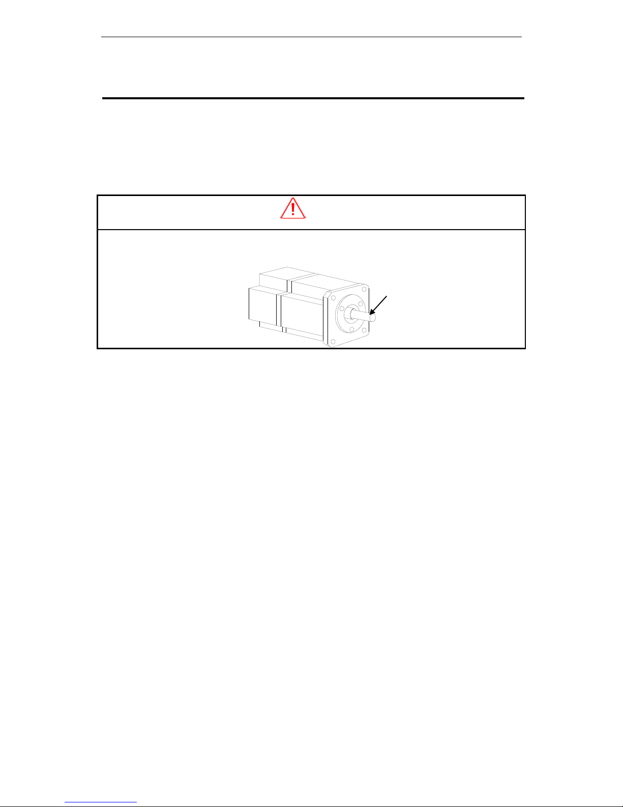
CAUTION
1. The end of the motor shaft is coated with antirust. Before installing, carefully remove all of the
paint using a cloth moistened with paint thinner.
2. Avoid getting thinner on other parts of the servomotor.
2-1-1.Storage Temperature
Store the servomotor within -20~+60 ℃ as long as it is stored with the power cable
disconnected.
2-1-2.Installation Site
MS series servomotors are designed for indoor use. Install the servomotor in environments
that satisfy the following conditions.
Free of corrosive or explosive gases.
Well-ventilated and free of dust and moisture.
Ambient temperature of 0° to 50°C.
Relative humidity (r.h.) of 20 to 80% with no condensation.
Accessible for inspection and cleaning.
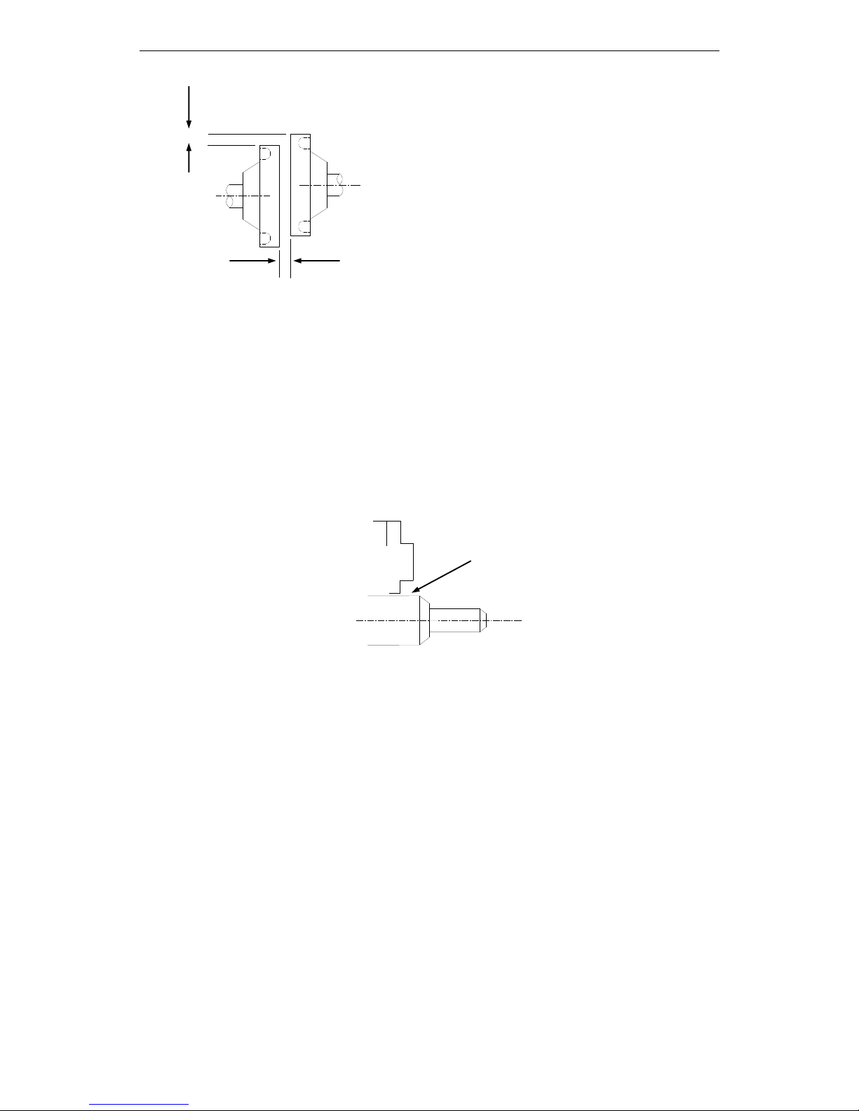
2-1-3.Concentricity
Please use coupling when connecting to machine; keep the shaft center of servo motor and
machine at the same line. It should be accord to the following diagram when installing the
servo motor.
Antirust
7
Note: (1) If the concentricity is not enough, it will cause the vibration and bearing
damage.
(2) When installing the coupler, prevent direct impact to the shaft. This can damage the
encoder mounted on the shaft end at the opposite side of the load.
2-1-4.Orientation
MS series servomotors can be installed either horizontally or vertically.
2-1-5.Handling Oil and Water
Install a protective cover over the servomotor if it is used in a location that is subject to
water or oil mist. Also use a servomotor with an oil seal when needed to seal the
through-shaft section.
2-1-6.Cable Stress
Make sure that the power lines are free from bends and tension. Be especially careful to
wire signal line cables so that they are not subject to stress because the core wires are very
thin, measuring only 0.2 to 0.3mm2.
2-2.Servo Drive
The DS2-AS series servo drives are compact model. Incorrect installation will cause
problems. Follow the installation instructions below
2-2-1.Storage Conditions
Store the servo drive within -20~+85℃, as long as it is stored with the power cable
disconnected.
2-2-2.Installation Site
The following precautions apply to the installation site.
Through part of the shaft
Measure it at 4 places of the circle, the difference should be
below 0.03mm. (Rotate with the shaft coupler)
Measure it at 4 places of the circle, the difference should be below
0.03mm. (Rotate with the shaft coupler)
8
Situation
Installation Precaution
Installation in a Control
Panel
Design the control panel size, unit layout, and cooling method so the
temperature around the servo drives does not exceed 50°C.
Installation Near a
Heating Unit
Minimize heat radiated from the heating unit as well as any temperature
rise caused by natural convection so the temperature around the servo
drives does not exceed 50°C.
Installation Near a Source
of Vibration
Install a vibration isolator beneath the servo drive to avoid subjecting it to
vibration.
Installation at a Site
Exposed to Corrosive Gas
Corrosive gas does not have an immediate effect on the servo drives, but
will eventually cause electronic components and terminals to malfunction.
Take appropriate action to avoid corrosive gas.
Other Situations
Do not install the servo drive in hot and humid locations or locations
subject to excessive dust or iron powder in the air.
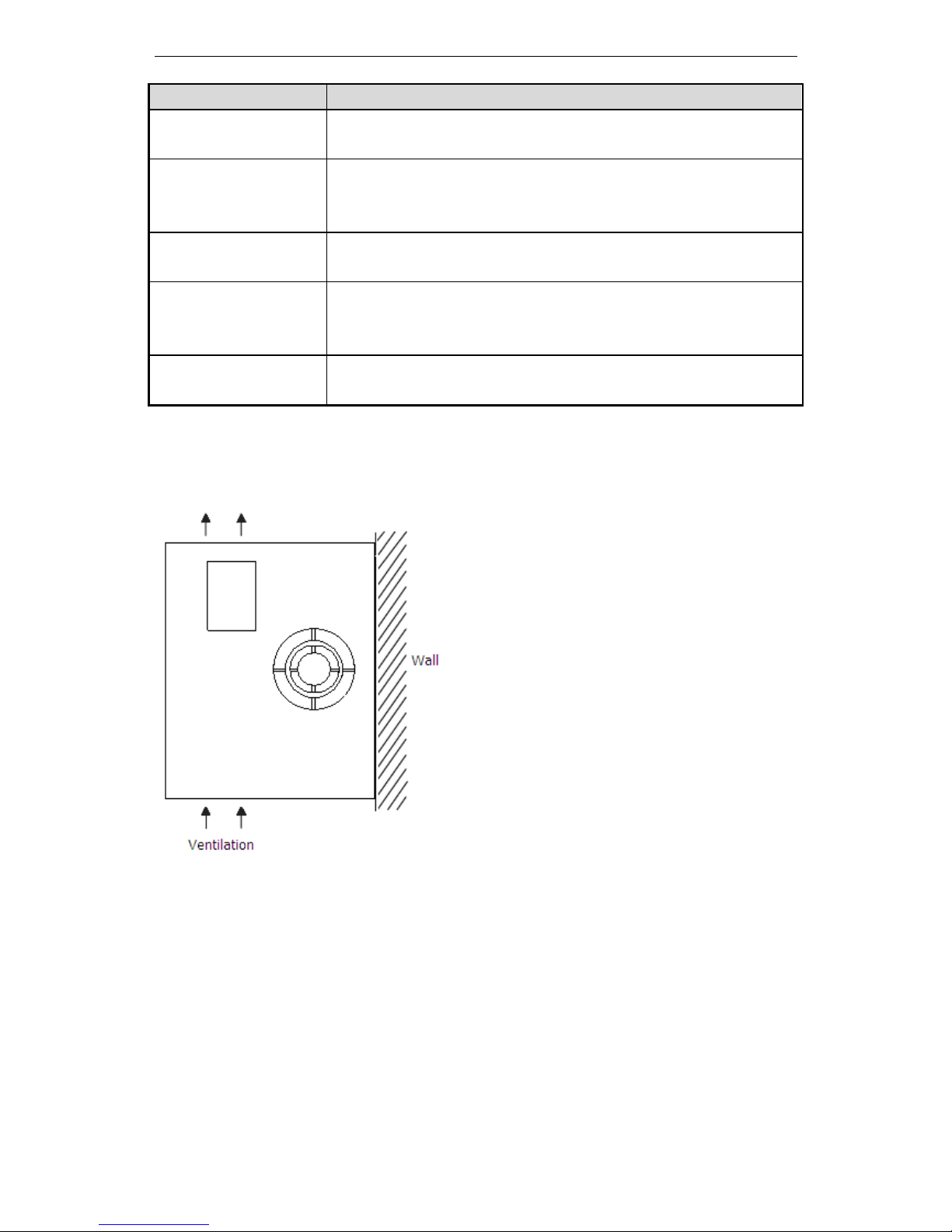
2-2-3.Orientation
Install the servo drive perpendicular to the wall as shown in the figure. The servo drive
must be oriented this way because it is designed to be cooled by natural convection or by a
cooling fan.
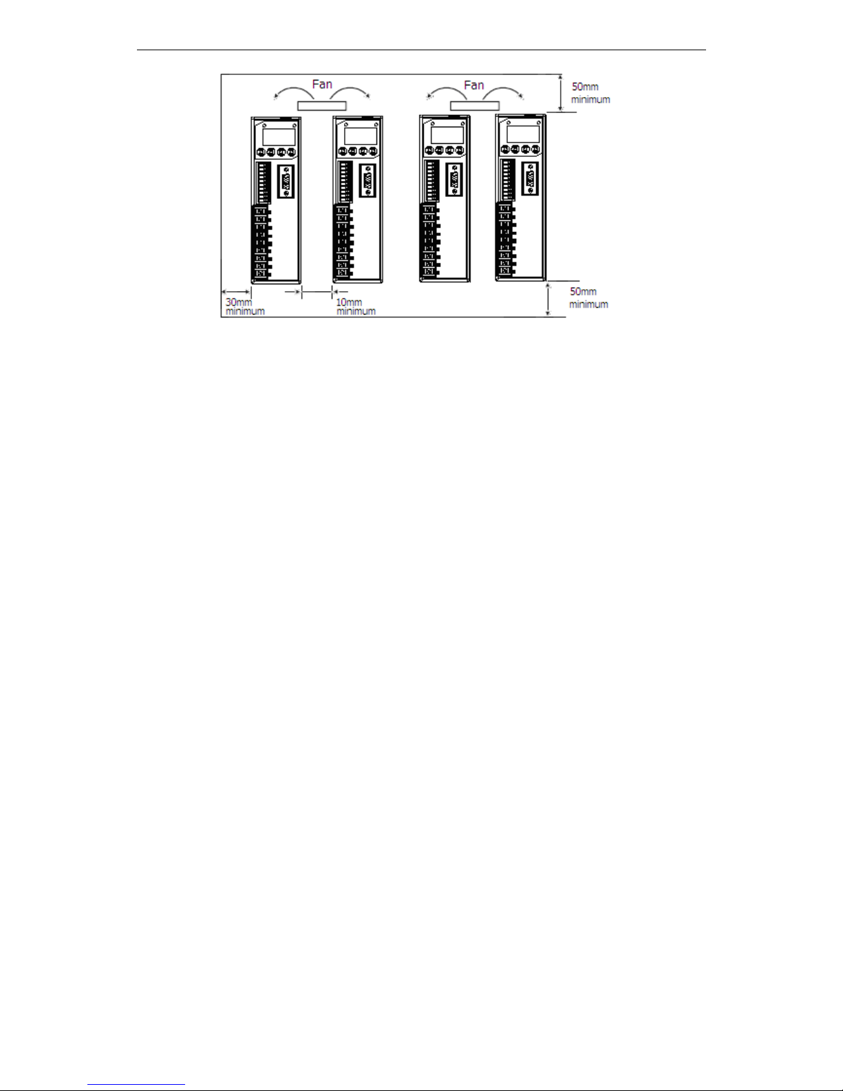
2-2-4.Installation
Follow the procedure below to install multiple servo drives side by side in a control panel.
9
Servo Drive Orientation
Install the servo drive perpendicular to the wall so the front panel containing connectors
faces outward.
Cooling
As shown in the figure above, allow sufficient space around each servo drive for cooling
by cooling fans or natural convection.
Side-by-side Installation
When install servo drives side by side as shown in the figure above, make at least 10mm
between and at least 50mm above and below each servo drive. Install cooling fans above
the servo drives to avoid excessive temperature rise and to maintain even temperature
inside the control panel.
Environmental Conditions in the Control Panel
Ambient Temperature: 0~50 ℃
Humidity: 90%RH or less
Vibration: 4.9m/s2
Condensation and Freezing: None
Ambient Temperature for Long-term Reliability: 50°C maximum
10
3 Wiring
3-1.Main Circuit Wiring
Caution
1. Do not bundle or run power and signal lines together in the same duct. Keep power and signal
lines separated by at least 11.81inch(30cm)
2. Use twisted pair wires or multi-core shielded-pair wires for signal and encoder (PG) feedback
lines.
The maximum length is 118.11 inch (3m) for reference input lines and is 787.40 inch (20m) for
encoder (PG) feedback lines.
3. Do not touch the power terminals for 5 minutes after turning power OFF because high voltage
may still remain in the servo amplifier.
Please make sure to check the wiring after the CHARGE light is going off.
4. Avoid frequently turning power ON and OFF. Do not turn power ON or OFF more than once per
minute.
Since the servo amplifier has a capacitor in the power supply, a high charging current flows for
0.2s when power is turned ON. Frequently turning power ON and OFF causes main power
devices like capacitors and fuses to deteriorate, resulting in unexpected problems.
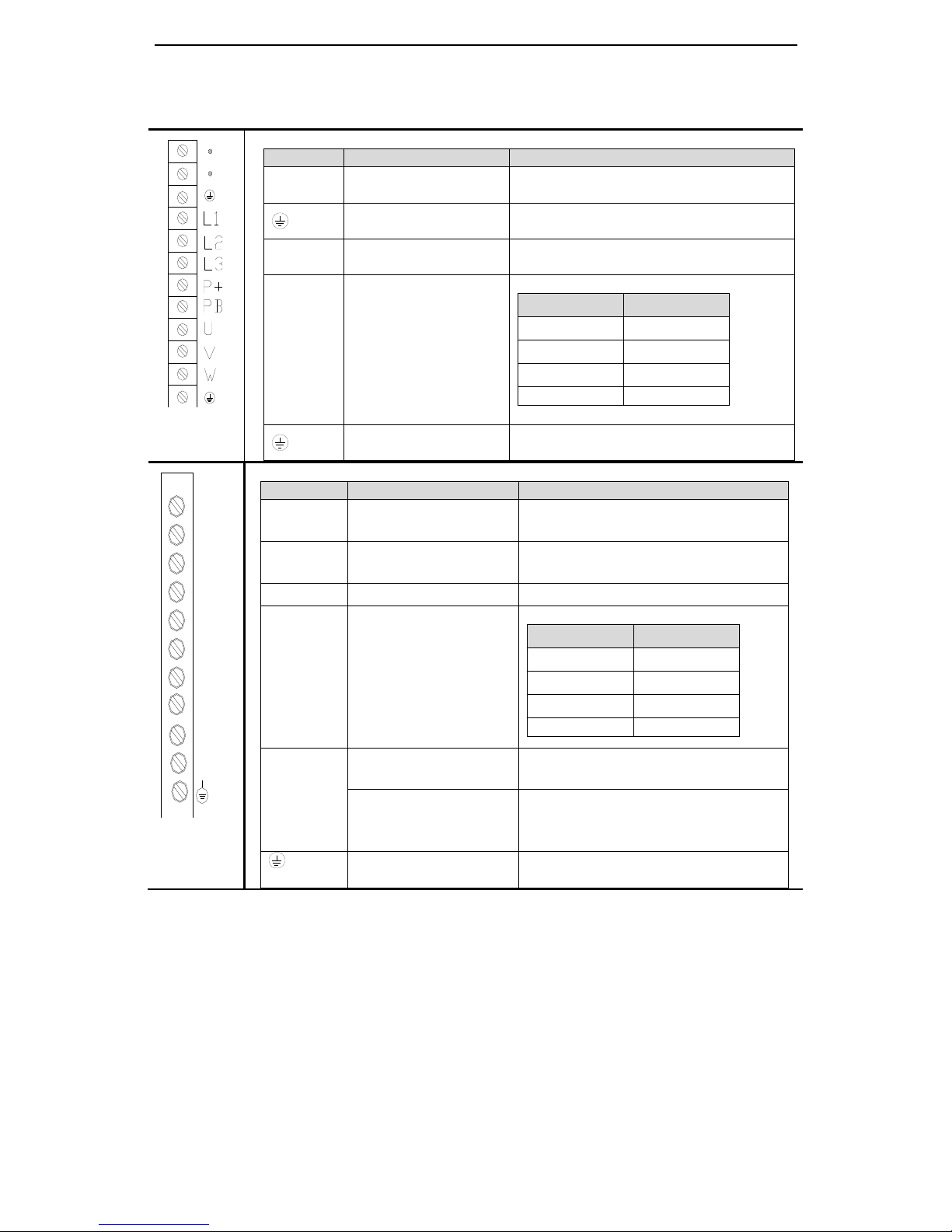
3-1-1.The terminal arrangement
11
3-1-2. Main circuit terminals
DS2-20P2-AS/AS6, DS2-20P4-AS/AS6, DS2-20P7-AS/AS6
Terminal
Function
Explanation
L1/L2/L3
Power supply input of
main circuit
Single or 3 phase AC 200~240V, 50/60Hz
Ground
Connect to ground terminal of motor then
connect to the ground
P+、PB
Regenerative resistor
Connect regenerative resistor between P+
and PB
U、V、W
Motor terminals
Connect the motor
Terminal
Color
U
brown
V
black
W
blue
PE
Yellow green
Ground
Connect to ground terminal of motor then
connect to the ground
DS2-21P5-AS/AS6/AS2, DS2-22P3-AS/AS6, DS2-41P5-AS/AS6
Terminal
Function
Explanation
R/S/T
Power supply input of
main circuit
3 phase AC 200~240V, 50/60Hz
(DS2-2□P□-AS)
R/S/T
Power supply input of
main circuit
3 phase AC 360~400V, 50/60Hz
(DS2-4□P□-AS)
●
Vacant
U、V、W
Motor terminals
Connect the motor
Terminal
Color
U
brown
V
black
W
blue
PE
Yellow green
P+、D、C
Internal regenerative
resistor
Short P+ and D, disconnect P+ and C,
set P0-10=0
External regenerative
resistor
Connect regenerative resistor between
P+ and C, disconnect P+ and D, set
P0-10=1
Ground
Connect to ground terminal of motor,
then connect to the ground
R
S
T
.
U
V
W
P+
D
C
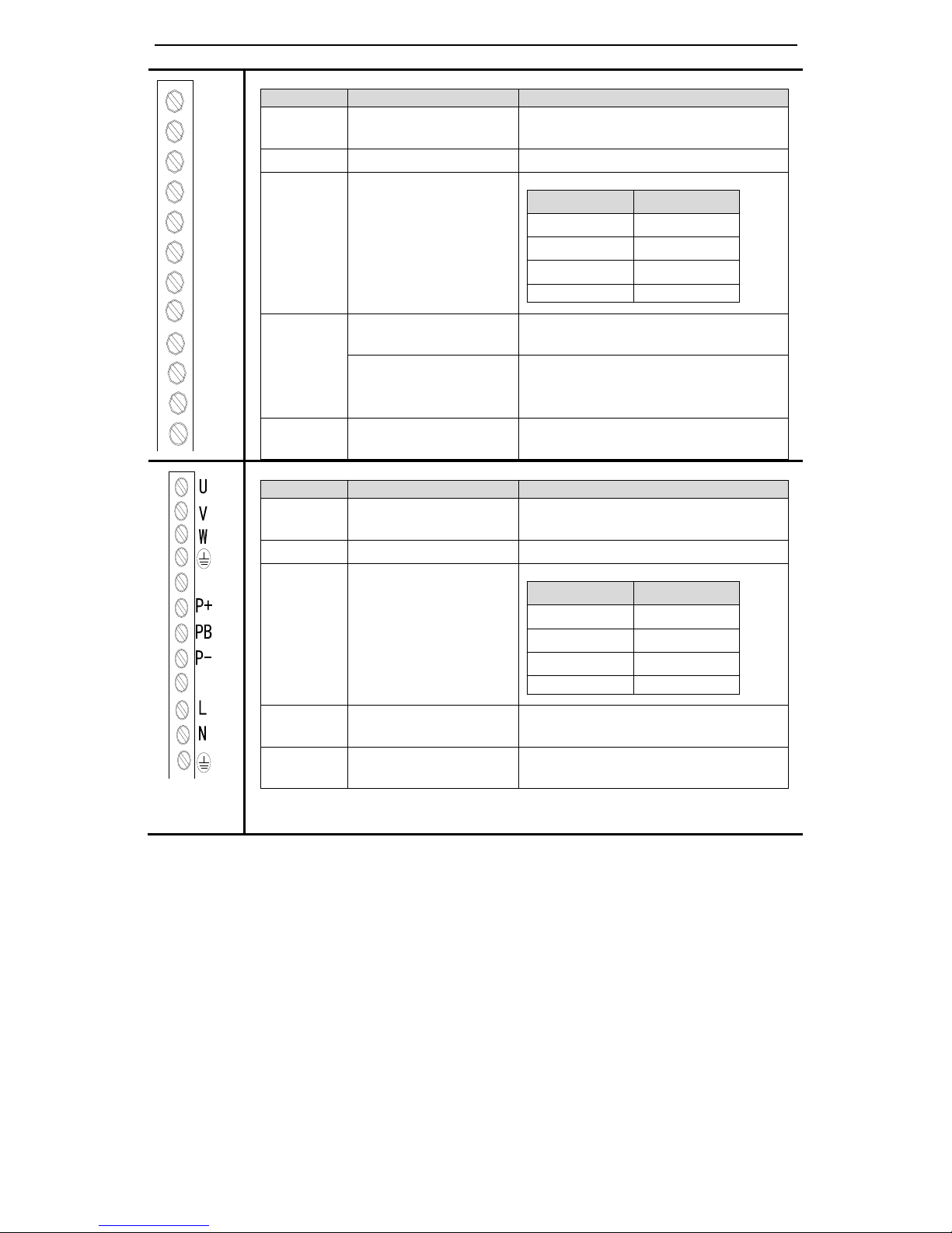
12
DS2-43P0-AS/AS6
Terminal
Function
Explanation
R/S/T
Power supply input of
main circuit
3 phase AC 360~400V, 50/60Hz
●
Vacant
U、V、W
Motor terminals
Connect the motor
Terminal
Color
U
brown
V
black
W
blue
PE
Yellow green
P+、D、C
Internal regenerative
resistor
Short P+ and D, disconnect P+ and C,
set P0-10=0
External regenerative
resistor
Connect regenerative resistor between
P+ and C, disconnect P+ and D, set
P0-10=1
P+/P-
Bus terminal
Real-time check the bus voltage, please
take attention of this terminal
DS2-20P4-BS/BS6
Terminal
Function
Explanation
L/N
Power supply input of
main circuit
Single phase AC 200~240V, 50/60Hz
●
Vacant
U、V、W
Motor terminals
Connect the motor
Terminal
Color
U
brown
V
black
W
blue
PE
Yellow green
P+/PB
External regenerative
resistor
Connect regenerative resistor between
P+ and PB
P+/P-
Bus terminal
Real-time check the bus voltage, please
take attention of this terminal
R
S
T
.
U
V
W
P+
D
C
P-
.
.
.
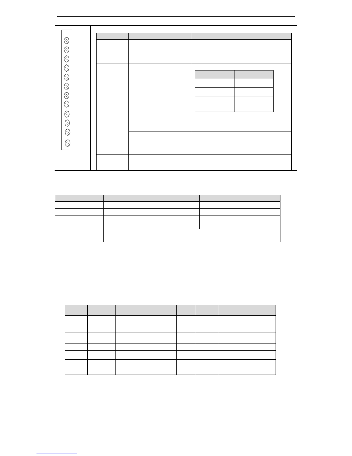
13
DS2-20P7-BSW/BSW6
Terminal
Function
Explanation
L/N
Power supply input of
main circuit
Single phase AC 200~240V, 50/60Hz
●
Vacant
U、V、W
Motor terminals
Connect the motor
Terminal
Color
U
brown
V
black
W
blue
PE
Yellow green
P+、D、C
Internal regenerative
resistor
Short P+ and D, disconnect P+ and C,
set P0-10=0
External regenerative
resistor
Connect regenerative resistor between
P+ and C, disconnect P+ and D, set
P0-10=1
P+/P-
Bus terminal
Real-time check the bus voltage, please
take attention of this terminal
3-1-3.Winding Terminals on Servo motor
Symbol
60, 80, 90 Series
110, 130, 180 Series
PE
4-yellow green (yellow green)
1-yellow green
U
1-brown (red)
2-brown
V
3-black (blue)
3-black
W
2-blue (yellow)
4-blue
Terminal for brake
1: +24V
2: GND
3-1-4.CN0, CN1, CN2 terminals
CN0 terminals
No.
Name
Explanation
No.
Name
Explanation
1
P-
Pulse input PUL-
8
SI2
Input 2
2
P+5V
5V difference input
9
SI3
Input 3
3
P+24V
Open collector input
10
SI4
Input 4
4
D-
Direction input DIR-
11
+24V
Input +24V
5
D+5V
5V difference input
12
SO1
Output 1
6
D+24V
Open collector input
13
SO2
Output 2
7
SI1
Input 1
14
COM
Ground of output
.
L
N
.
U
V
W
P+
D
C
P-
.
14
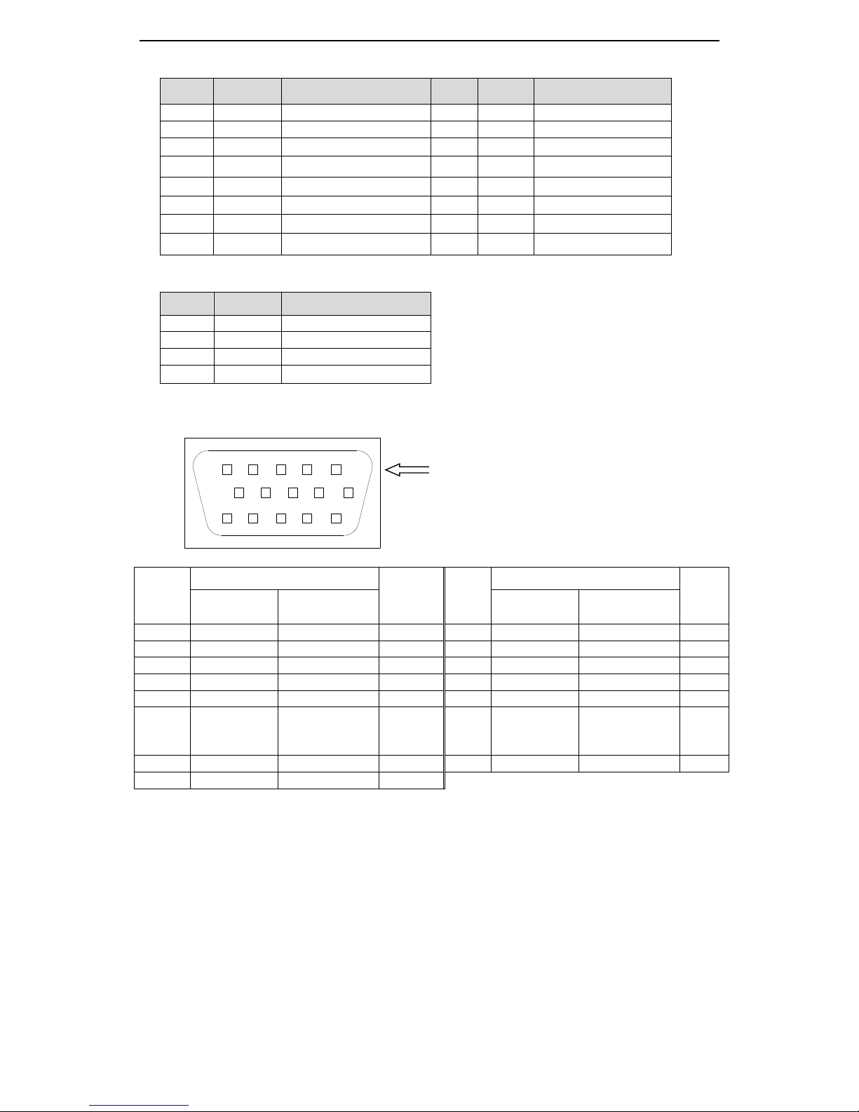
CN1 (DB15) terminals
No.
Name
Explanation
No.
Name
Explanation
1
NC
Reserved
9
Z-
Encoder output Z-
2
NC
Reserved
10
B+
Encoder output B+
3
SI5
Input 5
11
T-REF
Torque analog input
4
SO3
Output 3
12
V-REF
Speed analog input
5
B-
Encoder output B-
13
GND
GND for analog input
6
A+
Encoder output A+
14
A
RS485+
7
A-
Encoder output A-
15
B
RS485-
8
Z+
Encoder output Z+
CN1(DB15)terminals (DS2-20P4-BS/BS6, DS2-20P7-BSW/BSW6, DS2-21P5-AS2)
No.
Name
Explanation
1
NC
Reserved
2
NC
Reserved
3
SI5
Input 5
4
SO3
Output 3
CN2 terminals
Drive
port
Motor encoder port
Name
Drive
port
Motor encoder port
Name
60、80、90
series
110、130、180
series
60、80、90
series
110、130、180
series
1 9 4
A+ 2 4
5
B+ 3 7 6 Z+ 4 6
10
U+
5
11
12
W+ 6 13
7
A- 7 14
8
B- 8 5
9
Z-
9 8 13
U-
10
15
15
W-
11 1 1
Connect
to shield
layer
12 3 3
GND
13 2 2
5V
14
10
11
V+
15
12
14
V-
910
15 14 13
12
11
1
2
345
6
7
8
CN2: encoder port
15
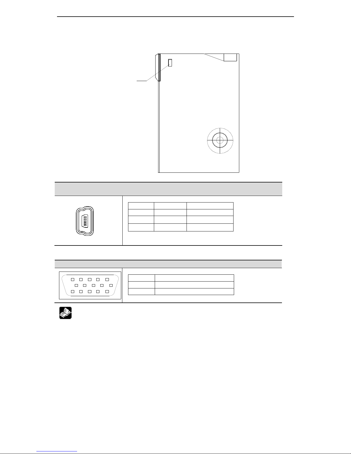
3-1-5. Communication port
RS-232 communication
DS2-2□P□-AS/AS6, DS2-20P4-BS/BS6, DS2-20P7-BSW/BSW6, DS2-21P5-AS2,
DS2-4□P□-AS/AS6
(5-pin port)
Pin no.
Name
Explanation
1
TXD
RS232 send
2
RXD
RS232 receive
3
GND
RS232 ground
RS-485 port
DS2-2□P□-AS/AS6, DS2-4□P□-AS/AS6
Pin no.
Name
CN1-14
A
CN1-15
B
(1) Please use the cable provide by XINJE Company.
(2) For above servo drives, RS232 (COM1) and RS485 (COM2) cannot be used at the
same time.
(3) The communication parameters of COM1 and COM2 will be changed at the same
time.
1
5
910
15 14 13
12
11
1
2
345
6
7
8
Communication port(RS232)
Can connect PC and HMI
16
P0-03, P0-04 set communication parameters
Parameter
Function
Default setting
Setting range
P0-04.0
Baud rate
6
0~9
0:300
1:600
2:1200
3:2400
4:4800
5:9600
6:19200
7:38400
8:57600
9:115200
P0-04.1
Data bit
0
0:8
P0-04.2
Stop bit
2
0:2 bits; 2:1 bit
P0-04.3
Parity bit
2
0~2
0:no parity 1:odd parity 2:even parity
Parameter
Function
Default setting
Setting range
Effective time
P0-03
Modbus station no.
1
1~255
Power on again
3-2.Signal terminals
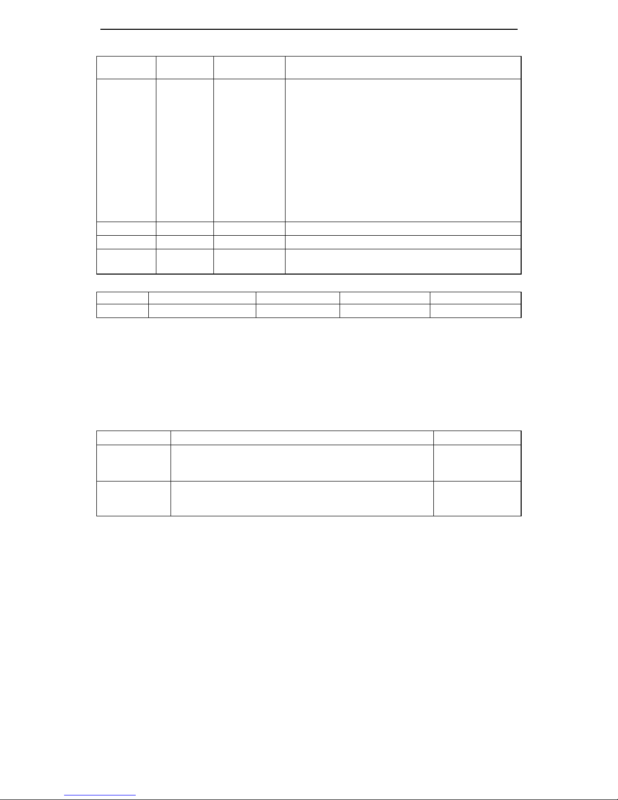
3-2-1. Pulse signal
Input terminal
Function
Reference chapter
PP+5V
P+24V
P2-00=0:CW, CCW two pulses mode
P2-00=2:pulse + direction mode
5-3-2
DD+5V
D +24V
P2-00=0:CW, CCW two pulses mode
P2-00=2:pulse + direction mode
5-3-2
17
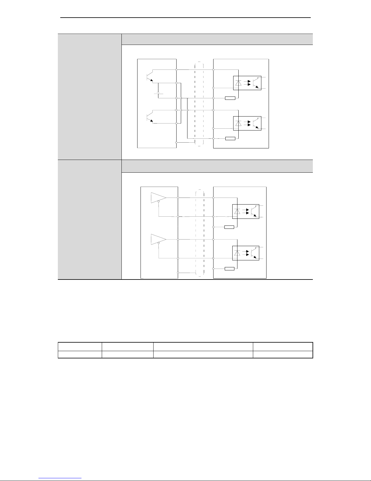
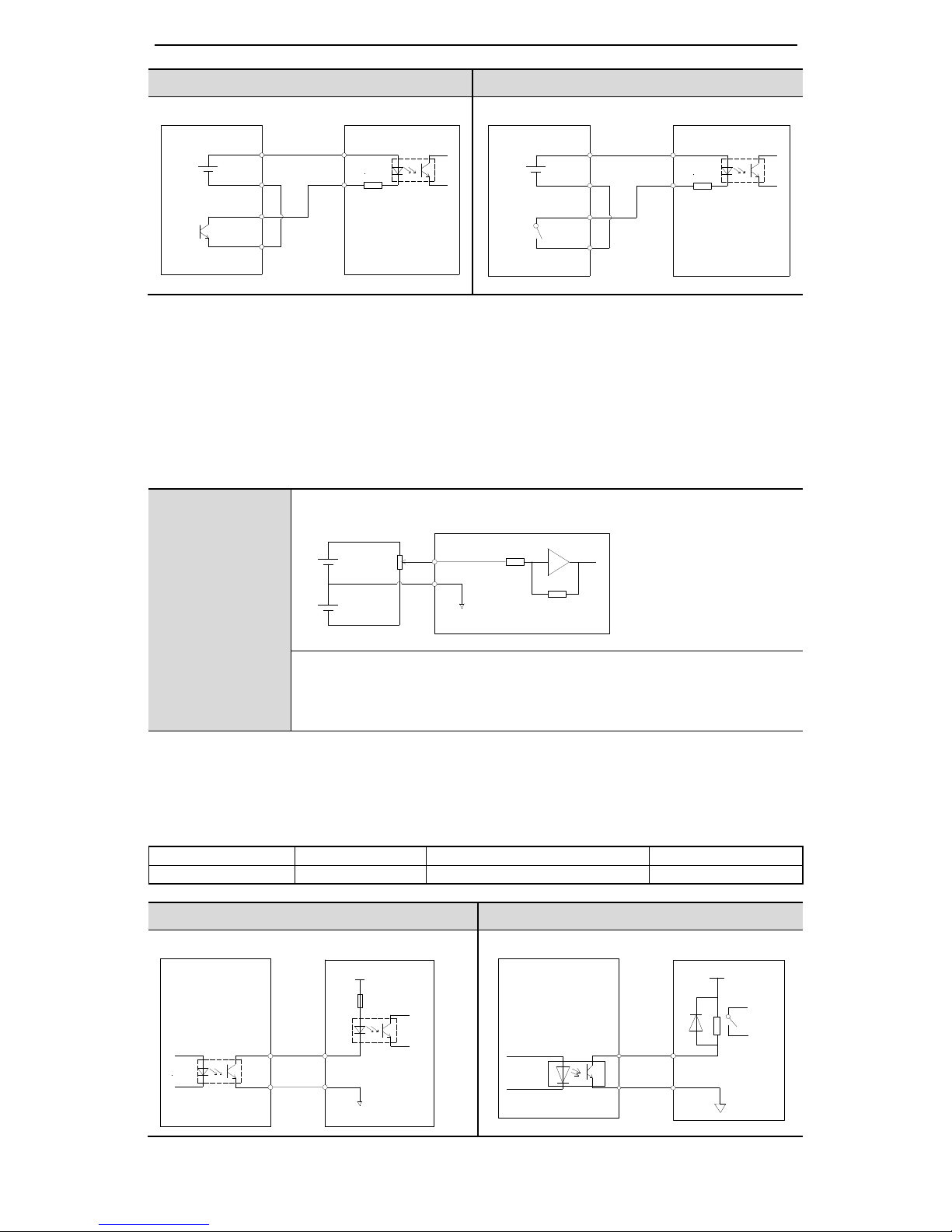
The interface circuit of Pulse + direction and CW, CCW mode:
DS2-2□P□-AS/AS6
DS2-4□P□-AS/AS6
DS2-20P4-BS/BS6
DS2-20P7-BSW/BSW6
DS2-21P5-AS2
Open collector (24V)
PLC, SCM, etc servo drive
DS2-2□P□-AS/AS6
DS2-4□P□-AS/AS6
DS2-20P4-BS/BS6
DS2-20P7-BSW/BSW6
DS2-21P5-AS2
Difference mode (5V)
PLC, SCM, etc servo drive
3-2-2.SI input signal
Please use relay or open collector transistor to connect. When using relay, please choose micro-current
relay. Otherwise, the contact will be not good.
Type
Input terminal
Function
Reference chapter
Digital input
SI1~SI5
Multi-functional input
5-12-1
P+24V
PUL+
PUL-
P-
R=3.3K
DIR-
D-
R=3.3K
P+5V
D+5V
Shield layer
0V
D+24V
DIR+
COM0
Y0
+24V
P-
R=3.3K
COM1
Y1
D-
R=3.3K
P+5V
D+5V
Shield layer
0V
D+24V
P+24V
When upper
device is open
collector output,
please use this
wiring diagram.
Please note:
P+5V and
D+5V must be
vacant.
When upper
device is 5V
difference
output, please
use this wiring
diagram. Please
note: P+24V
and D+24V
must be vacant.
18
+24V
Open collector (24V power supply)
Relay (24V power supply)
Upper device servo drive
Upper device servo drive
Note: the max allowable voltage and current of open collector output circuit:
Voltage: max DC30V
Current: max DC50mA
3-2-3. Analog input circuit
DS2-2□P□-AS/AS6
DS2-4□P□-AS/AS6
Upper device servo drive
Analog signal is speed command or torque command. Input impedance:
• speed command input: about 13KΩ
• torque command input: about 13KΩ
• max allowable voltage of input signal is ±10V
3-2-4. Output signal
Type
Output terminal
Function
Reference chapter
Optocoupler output
SO1~SO3
Multi-functional output terminal
5-12-3
Optocoupler type
Relay type
Servo drive upper device
Servo drive upper device
SI
+24V
+
COM2
Y2
0V
+24V
R=2.2KΩ
R=2.2KΩ
+24V
0V
Y2
COM2
+
+24V
SI
+10V
-10V
11 T-REF
12 V-REF
13 GND
0V
R=13KΩ
2KΩ
1W
COM
SO
X3
COM
0V
+24V
0V
COMX3COM
S0
19
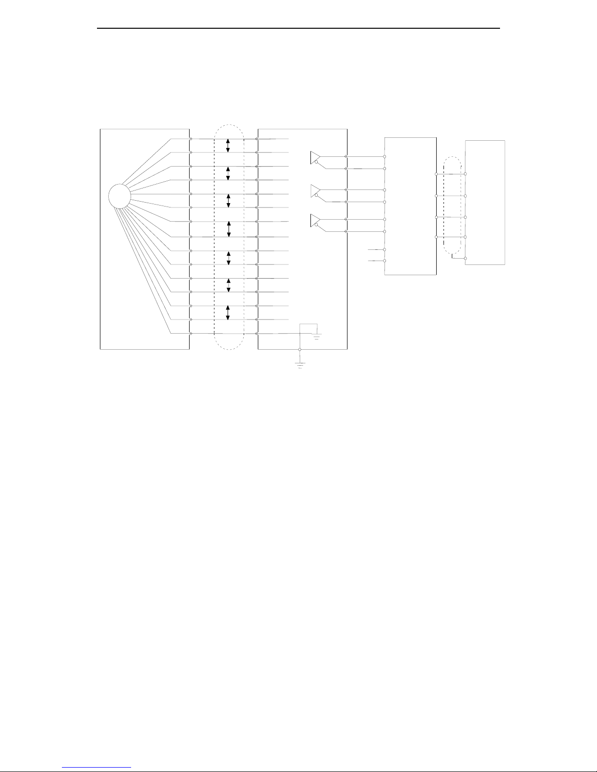
3-2-5. Encoder feedback signal
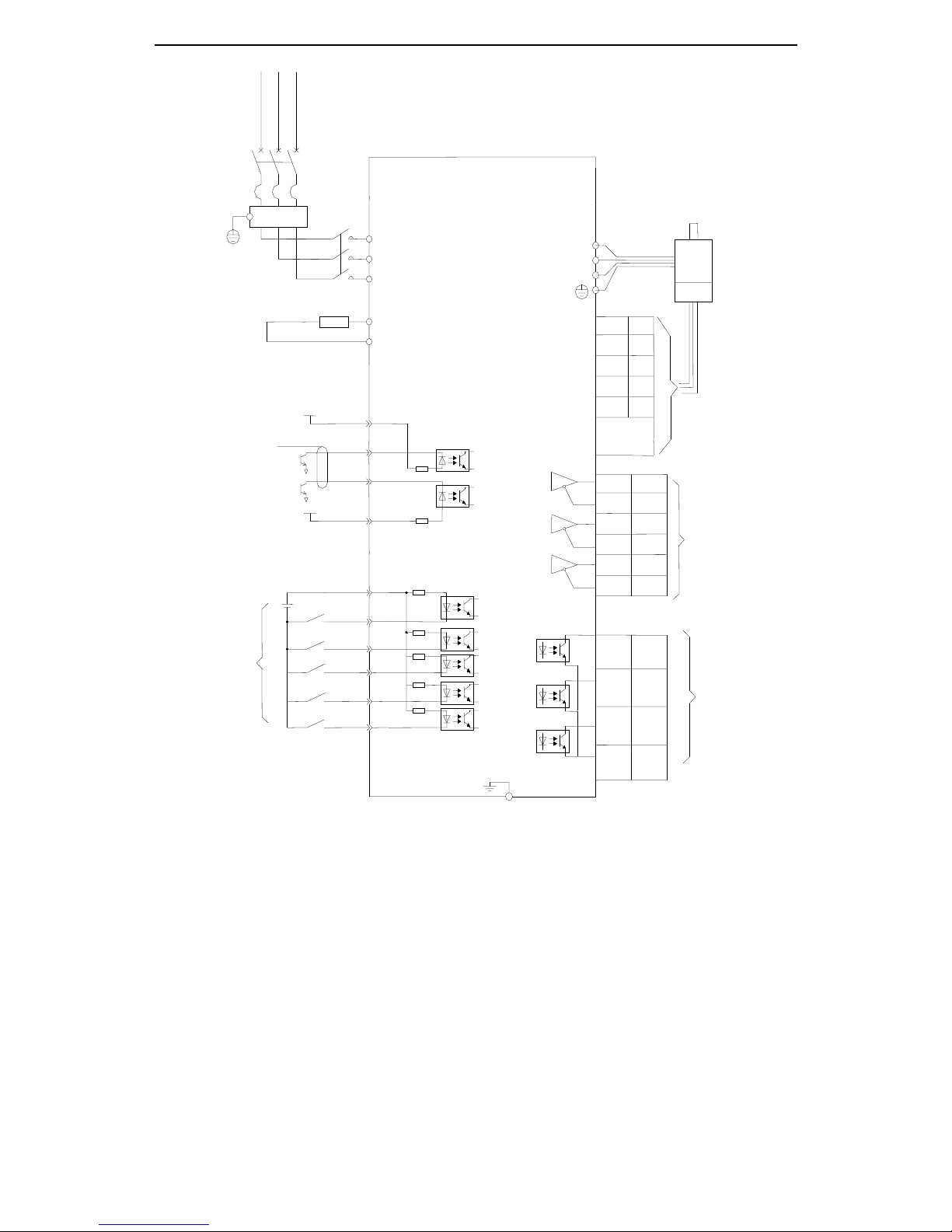
3-3. Standard wiring example
3-3-1.Position Control Mode
DS2-20P□-AS/AS6
PG
A+
A-
B+
B-
Z+
Z-
U+
U-
V+
V-
W+
W-
+5V
GND
SHIELD
cover
A+
A-
B+
B-
Z+
Z-
U+
U-
V+
V-
W+
W-
+5V
GND
Connector cover
CN2
AO+
AO-
BO+
BO-
ZO+
ZO-
0V
24V
AO+
AO-
BO+
BO-
ZO+
ZO-
X0
X1
X2
COM
Incremental encoder
Upper device
0V
Shield cable
Shiled layer
COM
Z B A
Servo unit
Differential to collector
20
Regenerative resistor
D+24V
D-
P-
CN0-6
CN0-4
CN1-7
CN1-6
CN1-3
CN0-9
/P-OT
/SPD-A
CN0-11
A0-
AO+
Shield layer connect
0V at signal side,
Be vacant at drive
side
Vcc
CN0-1
2.2K
Ω
W
V
Single phase / 3-phase AC 220V
(50/60Hz)
CN2
L1
FIL
Self-define the
Terminal function
CN0-8
CN0-7
/S-ON
+24VIN
U
L2
L3
CN0-10
/N-OT
/ALM-RST
3.3KΩ
P+24V
CN0-3
Vcc
2.2K
Ω
CN1-5
CN1-10
B0-
BO+
CN1-9
CN1-8
Z0-
ZO+
Servo motor
Encoder
CN2-5
W+
CN2-4
CN2-3
U+
Z+
CN2-2
CN2-1
B+
A+
. . .
.
.
.
Differential encoder
feedback
Self-define
The terminal
function
P+
PB
CN0-14
CN1-4
CN0-13
CN0-12
COM
S-RDY
ALM
COIN
21
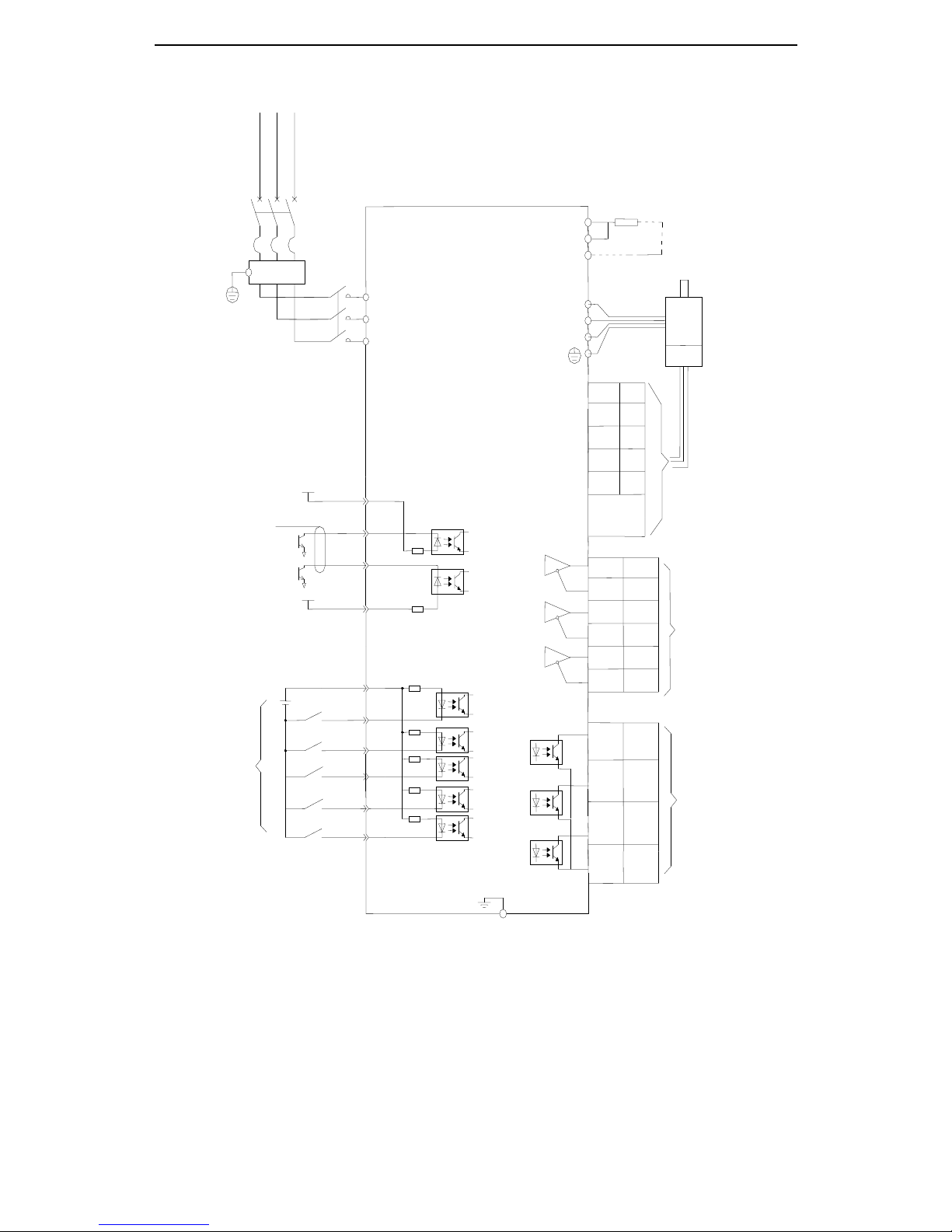
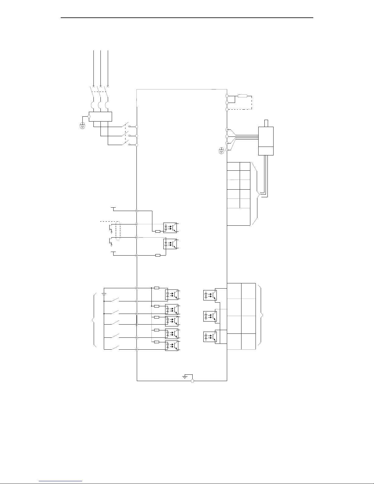
DS2-21P5-AS/AS6, DS2-22P3-AS/AS6, DS2-4□P□-AS/AS6
Note:
P+, D connect internal regenerative resistor. P+ and C connect external regenerative resistor.
CN0-11
A0-
AO+
COM
Shield layer connect
0V at signal side
Be vacant at
Drive side
Vcc
CN0-1
2.2
Ω
W V DS2-21P5-AS/AS6,DS2-22P3-AS/AS6: 3-phase AC220V (50/60Hz)
DS2-4□P□-AS/AS6: 3-phase AC380V (50/60Hz)
CN2
R
S-RDY
ALM
COIN
FIL
Self-define the
Terminals function
CN0-8
CN0-7
/S-ON
+24VIN
U S T
CN0-10
/N-OT
/ALM-RST
3.3KΩ
P+24V
CN0-3
Vcc
2.2
Ω
CN1-5
CN1-10
B0-
BO+
CN1-9
CN1-8
Z0-
ZO+
C
D
P+
Servo motor
Encoder
CN2-5
W+
CN2-4
CN2-3
U+
Z+
CN2-2
CN2-1
B+
A+
.
.
. . .
.
Differential encoder
feedback
Self-define
the terminals
function
D+24V
D-
P-
CN0-6
CN0-4
CN1-7
CN1-6
CN0-14
CN1-4
CN0-13
CN0-12
CN1-3
CN0-9
/P-OT
/SPD-A
Regenerative resistor
22
DS2-20P4-BS/BS6, DS2-20P7-BSW/BSW6, DS2-21P5-AS2
Note:
P+, D connect internal regenerative resistor. P+ and C(PB) connect external regenerative resistor.
D+24V
D-
P-
CN0-6
CN0-4
CN0-14
CN1-4
CN0-13
CN0-12
CN1-3
CN0-9
/P-OT
/SPD-A
CN0-11
COM
Shield layer connect
0V at signal side
Be vacant at
Drive side
Vcc
CN0-1
2.2K
Ω
W
V
DS2-20P4-BS/BS6:single phase AC220V (50/60Hz)
CN2
R/L
S-RDY
ALM
COIN
FIL
Self-define the output terminals
CN0-8
CN0-7
/S-ON
+24VIN
U
S/N
T
CN0-10
/N-OT
/ALM-RST
3.3KΩ
P+24V
CN0-3
Vcc
2.2K
Ω
PB/C
D
P+
Servo motor
Encoder
CN2-5
W+
CN2-4
CN2-3
U+
Z+
CN2-2
CN2-1
B+
A+
. . .
. . .
Self-define
the terminals
function
Regenerative resistor
DS2-21P5-AS2: 3 phase AC220V (50/60Hz)
DS2-20P7-BSW/BSW6: single phase AC220V (50/60Hz)
 Loading...