


WUXI XINJE ELECTRIC CO., LTD.
DS2 series servo drive
Manual
Data No.: SC209 20130116 1.0

2

1
►► Safety notes
Confirmation
Do not use the drivers that are broken, lack of parts or wrong types.
Installation
Make sure all the external powers are cut off before install the drivers.
Wiring
Please cut off all the powers before wiring.
Connect the AC power to the power terminals of driver.
Do not connect U, V, W terminals of driver with 3-phase power supply.
Please use 2mm2 cables to ground the GND terminal of driver.
Maintenance and running
Install the panel cover when power on.
Do not touch the terminals in 5 minutes after power off.
Do not connect motor with load when test running.
Set the suitable power consumption parameters before connecting the machine.
Do not change the wiring with electricity.
Do not touch the radiator when running.
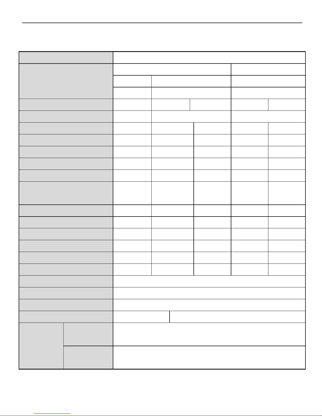
►► Confirmation after getting the products
1. Please confirm the following items after getting the products.
Item
Contents
The type is what you ordered?
Check the label of driver and motor
Does the motor shaft rotate well?
Can rotate by manual. Cannot rotate by manual for
brake types
Is there any damage?
Check if the cover has damage during transporting
Is the screw loose?
Check the screw with screwdriver
Check the motor code
Check if the driver and the motor code is matched
Please contact us if there are any problems in these items.
2. Type
(1) Servo driver

2
DS2 – 2 0P7 – AS
(2) Servo motor
MS -80 ST - M 02430 A Z- 2 0P7
Power
Voltage
Power-loss brake
Shaft specs
Feature code
Feedback part code
Sine drive motor
Base code
Series name
Base code: 60, 80, 90,110,130,180;
Feedback part code: M (optical pulse encoder)
Feature code: first 3 bits are rated torque; last 2 bits are rated speed;
For example: 00630: rated torque 0.637N·m, rated speed 3000rpm;
01330: rated torque 1.3N·m, rated speed 3000rpm;
Shaft spec: A- no bond; B- with bond;
Power-loss brake: empty- no brake; Z- with brake;
Voltage level: 2-220V;4 -380V
Power: 0P2: 0.2KW; 0P4: 0.4KW; 0P7: 0.75KW,1P5:1.5KW;2P3:2.3KW ;3P0:3.0KW
Voltage level
2: 220V
4:380V
Series name
DS2:compact model
Motor capacity
0P2: 0.2KW
0P4: 0.4KW
0P7: 0.75KW
1P5:1.5 KW
2P3:2.3 KW
3P0:3.0 KW
Configuration:
AS/AS2/AS6
BS/BS6
BSW/BSW6
3
3. Specification
(1) servo motor
Voltage level
220V
Motor type MS-
60ST-
80ST-
M00630
M01330
M02430
□□-20P2
□□-20P4
□□-20P7
Motor code
1003
0004
1004
0011
1011
Rated power (KW)
0.2
0.4
0.75
Rated current(A)
1.8
2.5
1.8
3.0
2.6
Rated speed(rpm)
3000
3000
3000
3000
3000
Max speed (rpm)
4000
4000
4000
4000
4000
Rated torque(N·m)
0.637
1.27
1.27
2.39
2.39
Peak torque(N·m)
1.91
3.8
3.8
7.1
7.1
Back EMF constant
(V/krpm)
26
28
162
48
56.6
Torque coefficient(N·m/A)
0.37
0.5
0.68
0.8
0.92
Rotor inertia(Kg·m2)
0.18×10⁻⁴
0.438×10⁻⁴
0.53×10⁻⁴
1.82×10⁻⁴
0.65×10⁻³
Winding resistor (Ω)
3.5
3.49
3.80
2.88
2.7
Winding inductance(mH)
8.32
8.47
11.51
6.40
6.25
Electrical time constant(ms)
2.38
2.43
3.03
2.22
2.3
Weight(Kg)
1.1
1.8
1.7
2.9
2.87
Encoder ppr(PPR)
2500
Pole pairs
4
Motor insulation level
Class B(130℃)
Protection level
IP64
IP65
Use
condition
Environment
temperature
-20℃~+50℃
Environment
humidity
Under 90% RH(no condensation)

4
Voltage level
220V
Motor type MS-
80ST-
90ST-
110ST-
M03520
M02430
M04030
M05030
□□-20P7
□□-21P2
□□-21P5
Motor code
0012
0021
0031
0032
Rated power (KW)
0.75
0.75
1.2
1.5
Rated current (A)
3.0
3.0
5.0
6.0
Rated seed (rpm)
2000
3000
3000
3000
Max speed (rpm)
2500
4000
3500
3500
Rated torque(N·m)
3.5
2.4
4
5
Peak torque (N·m)
10.5
7.1
12
15
Back EMF constant(V/krpm)
71
51
54
62
Torque coefficient(N·m/A)
1.17
0.8
0.8
0.83
Rotor inertia(Kg·m2)
2.63×10⁻⁴
2.45×10⁻⁴
0.54×10⁻³
0.63×10⁻³
Winding resistor(Ω)
3.65
3.20
1.09
1.03
Winding inductance(mH)
8.80
7.00
3.30
3.43
Electrical time constant(ms)
2.41
2.19
3.03
3.33
weight(Kg)
3.7
3.4
5.5
6.1
Encoder line number(PPR)
2500
Pole pairs
4
Motor insulation level
Class B(130℃)
Protection level
IP65
Use condition
Environment
-20℃~+50℃

5
temperature
Environment
humidity
Under 90% RH(no condensation)
Voltage level
220V
Motor type MS-
130ST-
M06025
M10015
M07725
□□-21P5
□□-22P0
Motor code
0042
1042
0044
0043
Rated power (KW)
1.5
1.5
1.5
2.0
Rated current(A)
6.0
7.4
6.0
7.5
Rated speed (rpm)
2500
2500
1500
2500
Max speed(rpm)
3000
3000
2000
3000
Rated torque(N·m)
6 6 10
7.7
Peak torque (N·m)
18
18
25
22
Back EMF constant(V/krpm)
65
82
103
68
Torque coefficient(N·m/A)
1.0
0.81
1.67
1.03
Rotor inertia(Kg·m2)
1.26×10⁻³
0.84×10⁻³
1.94×10⁻³
1.53×10⁻³
Winding resistor(Ω)
1.21
0.70
1.29
1.01
Winding inductance(mH)
3.87
5.07
5.07
2.94
Electrical time constant(ms)
3.20
7.24
3.93
2.91
Weight (Kg)
8.9
7.2
11.5
10.0
Encoder line number(PPR)
2500
Pole pairs
4

6
Motor insulation level
Class B(130℃)
Protection level
IP65
Use
condition
Environment
temperature
-20℃~+50℃
Environment
humidity
Under 90% RH(no condensation)
Voltage level
220V
380V
Motor type MS-
130ST-
110ST-
130ST-
M15015
M04030
M05030
M06025
□□-22P3
□□-41P2
□□-41P5
□□-41P5
Motor code
0046
0131
0132
0142
Rated power(KW)
2.3
1.2
1.5
Rated current(A)
9.5
3.0
3.9
3.7
Rated speed (rpm)
1500
3000
3000
2500
Max speed (rpm)
2000
3500
3500
3000
Rated torque (N·m)
15
4 5 6
Peak torque (N·m)
30
12
15
18
Back EMF constant
(V/krpm)
114
89
90
110
Torque coefficient(N·m/A)
1.58
1.33
1.11
1.62
Rotor inertia(Kg·m2)
2.77×10⁻³
0.54×10⁻³
0.63×10⁻³
1.26×10⁻³
Winding resistor (Ω)
1.10
3.30
2.28
3.50
Winding inductance(mH)
4.45
8.78
7.40
10.75
Electrical time constant(ms)
4.05
2.66
3.25
3.07
Weight (Kg)
14.4
5.5
6.1
8.9

7
Encoder line number(PPR)
2500
Pole pairs
4
Motor insulation level
Class B(130℃)
Protection level
IP65
Use
condition
Environment
temperature
-20℃~+50℃
Environment
humidity
Under 90% RH(no condensation)
Voltage level
380V
Motor type MS-
130ST-
180ST-
M10015
M10030
M19015
M20015
□□-41P5
□□-43P0
□□-43P0
□□-43P0
Motor code
0144
1148
0156
1052
Rated power(KW)
1.5
3.0
3.0
3.0
Rated current(A)
3.5
6.4
7.5
7.8
Rated speed (rpm)
1500
3000
1500
1500
Max speed (rpm)
2000
3500
2000
2000
Rated torque(N·m)
10
10
19
20
Peak torque(N·m)
25
25
47
50
Back EMF constant
(V/krpm)
177
88.3
158
138
Torque coefficient(N·m/A)
2.86
1.56
2.53
2.56
Rotor inertia(Kg·m2)
1.94×10⁻³
1.125×10⁻³
3.8×10⁻³
2.8×10⁻³
Winding resistor (Ω)
4.37
0.46
1.15
0.67
Winding inductance(m H)
15.00
1.52
6.4
2.68

8
Electrical time constant(ms)
3.46
3.33
5.57
4.00
Weight (Kg)
11.5
11.4
20.5
17.1
Encode line number(PPR)
2500
Pole number
4
Motor insulation level
Class B(130℃)
Protection level
IP65
Use condition
Environment
temperature
-20℃~+50℃
Environment
humidity
Under 90% RH(no condensation)
(2) servo drive
Servo element
DS2 series 220V
DS2 series 380V
Suitable encoder
Incremental encoder (2500 ppr)
Input power
DS2-2□P□-□: single/three phases AC200~240V,
50/60Hz
DS2-4□P□-□: three-phases AC380~400V, 50/60Hz
【note:DS2-2□P□-□:
Under 1.5KW(not including 1.5KW)may use three
phases AC200~240V 50/60Hz;
Above 1.5KW(including 1.5KW)suggest use three
phases AC200~240V 50/60Hz
Control mode
Three phases full wave rectification IGBT PWM
control, sine current drive mode
Use
Temperature
0~+50 ℃/-20~+85 ℃
9
condition
Humidity
Under 90% RH(no condensation)
Vibration
resistance/impact
resistance
4.9m/s
2
/ 19.6m/s2
Structure
Foundation installation
3.
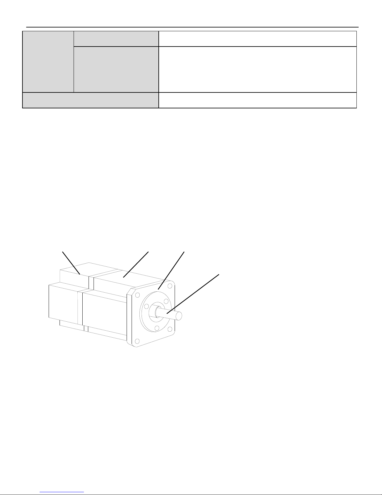
4. Parts introduction
(1) Servo motor
Encoder
Frame
Flange
Output shaft
10
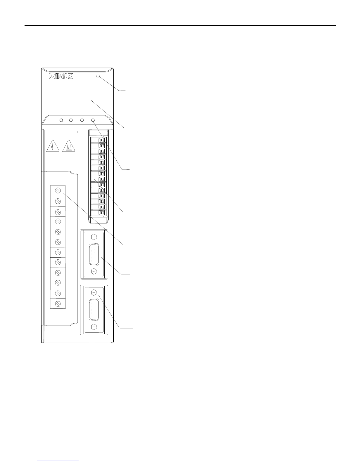
(2) Servo drive
PUL-
PUL+
V1+
DIR-
DIR+
V2+
SI1
SI2
SI3
SI4
+24V
SO1
SO2
COM
POWER
Light when power on
Panel buttons
For parameter settings
Panel display
Display the servo state, parameter, alarm
CN2
CN1
CN0
Pulse, direction, I/O signal
CN1
I/O, analog, position feedback signal
CN2
Encoder terminal
Power and motor terminal
Drive and motor power terminal
11
通讯端口(RS232通讯)
可连接电脑和触摸屏
►► Installation
1. Servo motor
MS series servo motors can be installed either horizontally or vertically. The service life of
the servo motor can be shortened or unexpected problems might occur if it is installed
incorrectly or in an inappropriate location. Follow these installation instructions carefully.
(1) Storage temperature
Store the servomotor within -20~+60 ℃ as long as it is stored with the power cable
disconnected.
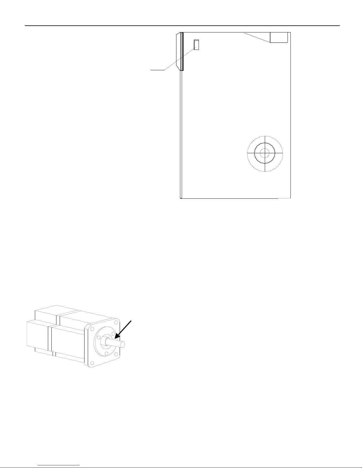
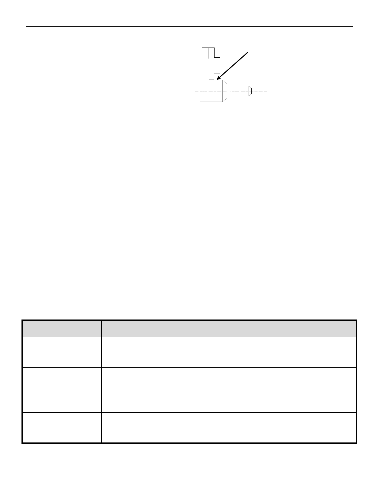
Notes:
The end of the motor shaft is coated with
antirust. Before installing, carefully remove all
of the paint using a cloth moistened with paint
thinner. Avoid getting thinner on other parts of
the servo motor.
Antirust
Communication port
(RS232 communication )
can connect to computer and
touch screen
12
(2) Installation location
Free of corrosive or explosive gases.
Well-ventilated and free of dust and moisture.
Ambient temperature of 0° to 50°C.
Relative humidity (r.h.) of 20 to 80% with no condensation.
Accessible for inspection and cleaning.
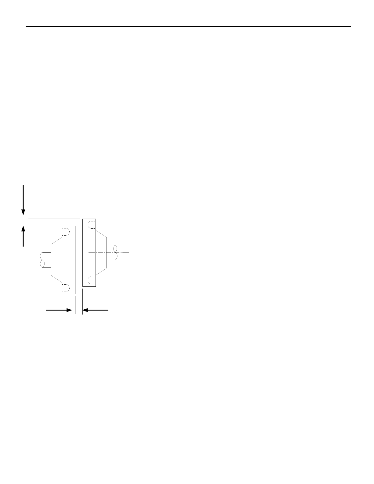
(3) Concentricity
Please use coupling when connecting to machine; keep the shaft center of servo motor and
machine at the same line. It should be accord to the following diagram when installing the
servo motor.
Note:
If the concentricity is not enough, it will cause the vibration and bearing damage.
When installing the coupler, prevent direct impact to the shaft. This can damage the
encoder mounted on the shaft end at the opposite side of the load.
(4) Installation direction
MS series servo motors can be installed either horizontally or vertically.
Measure it at 4 places of the circle, the difference should be below
0.03mm. (Rotate with the shaft coupler)
Measure it at 4 places of the circle, the difference should be below
0.03mm. (Rotate with the shaft coupler)
13
(5) Avoid oil and water
Install a protective cover over the
servomotor if it is used in a location that is
subject to water or oil mist. Also use a
servomotor with an oil seal when needed to
seal the through-shaft section.
(6) Cable stress
Make sure that the power lines are free from bends and tension. Be especially careful to
wire signal line cables so that they are not subject to stress because the core wires are very
thin, measuring only 0.2 to 0.3mm2.
2. Servo drive
The DS2 series servo drivers are base-mounted servo drivers. Incorrect installation will
cause problems. Follow the installation instructions below:
(1) Storage temperature
Store the servo driver within -20~+85℃ , as long as it is stored with the power cable
disconnected.
(2) Installation location
The following precautions apply to the installation site.
Situation
Installation Precaution
Installation in a
Control Panel
Design the control panel size, unit layout, and cooling method so the
temperature around the servo drivers does not exceed 50°C.
Installation Near a
Heating Unit
Minimize heat radiated from the heating unit as well as any
temperature rise caused by natural convection so the temperature
around the servo drivers does not exceed 50°C.
Installation Near a
Source of Vibration
Install a vibration isolator beneath the servo driver to avoid subjecting
it to vibration.
Through part of the shaft
14
Installation at a Site
Exposed to
Corrosive Gas
Corrosive gas does not have an immediate effect on the servo drivers,
but will eventually cause electronic components and terminals to
malfunction. Take appropriate action to avoid corrosive gas.
Other Situations
Do not install the servo driver in hot and humid locations or locations
subject to excessive dust or iron powder in the air.
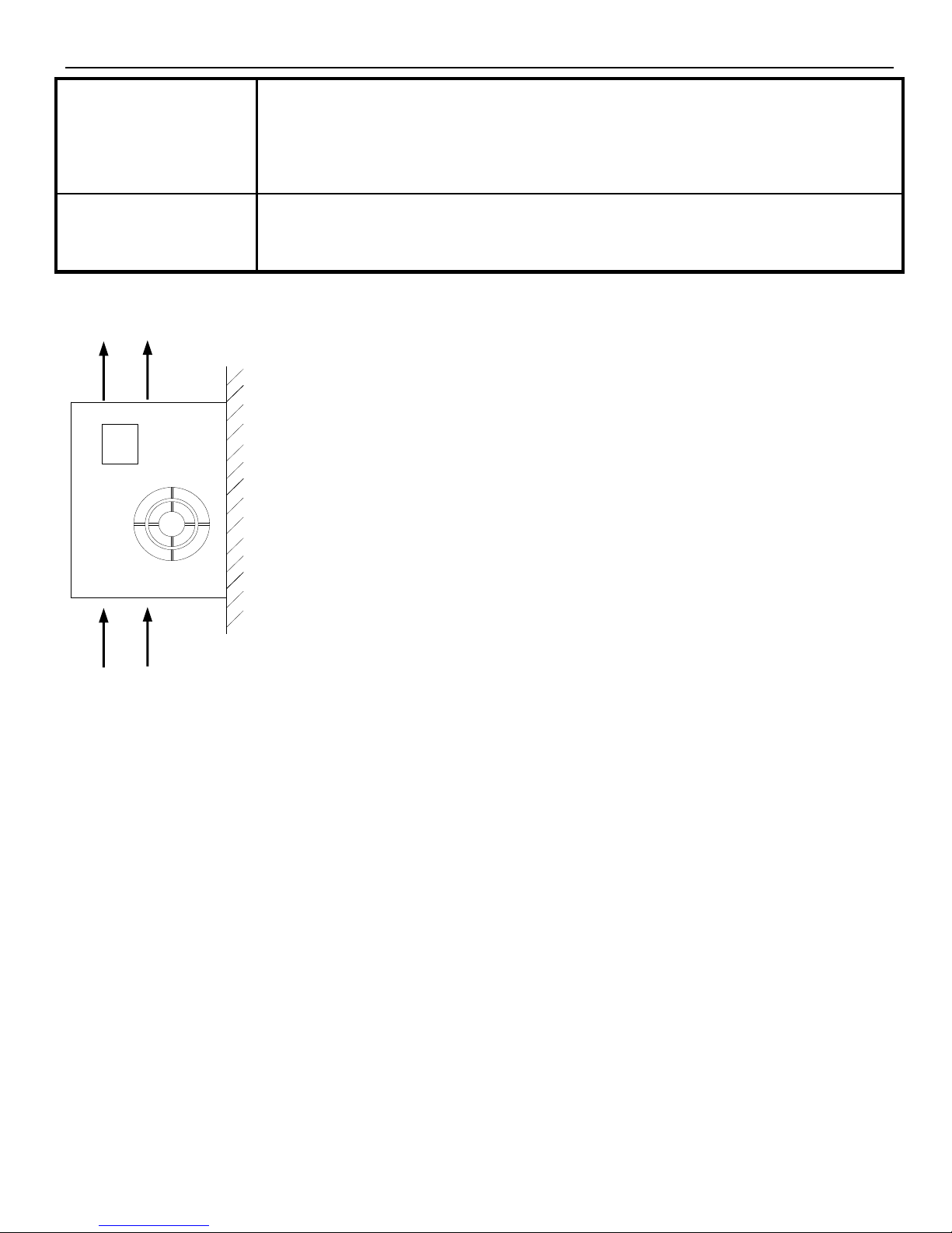
(3) Installation direction
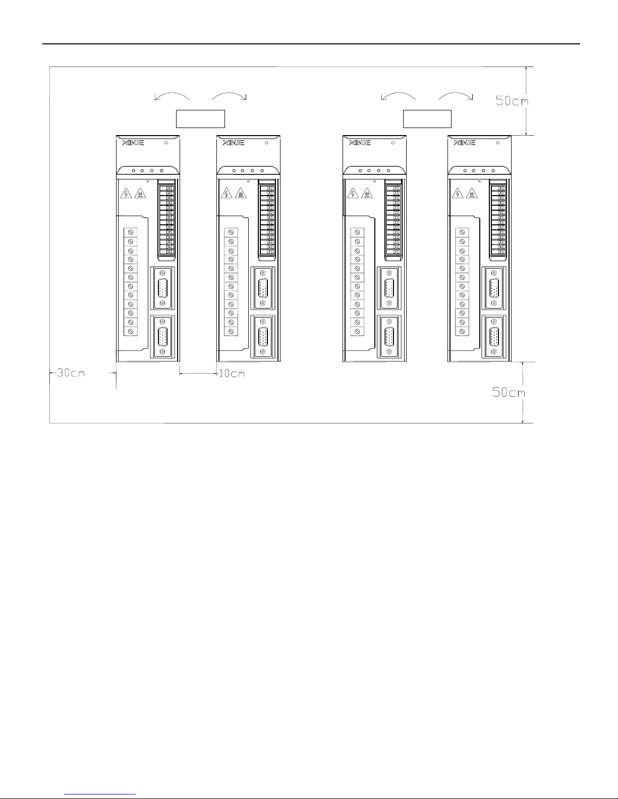
(4) Installation
Follow the procedure below to install multiple servo drivers side by side in a control panel.
Install the servo driver perpendicular to the wall as shown
in the figure. The servo driver must be oriented this way
because it is designed to be cooled by natural convection
or by a cooling fan. Please must follow the installation
direction requirements. For the driver with internal at the
bottom ,please pay attention to the installation face
cooling, void the driver overheat ,or cause fire accident.
Wall
Ventilation
15
Servo drive direction
Install the servo driver perpendicular to the wall and make the front panel towards
operator.
Cooling
Please leave enough space as the above diagram to ensure cooling by fans or natural
ventilation.
Side-by-side installation
As the above diagram, leave min 10cm space at horizontal direction, leave min 50mm
space at vertical direction. Install cooling fans above the drive. Keep the uniform
temperature inside the control panel to avoid overheat at local place.
Temperature in the control panel
Servo driver temperature: 0~50 ℃
PUL-
PUL+
V1+
DIR-
DIR+
V2+
SI1
SI2
SI3
SI4
+24V
SO1
SO2
COM
CN2
CN1
min
min
min
min
Fan
Fan
PUL-
PUL+
V1+
DIR-
DIR+
V2+
SI1
SI2
SI3
SI4
+24V
SO1
SO2
COM
CN2
CN1
PUL-
PUL+
V1+
DIR-
DIR+
V2+
SI1
SI2
SI3
SI4
+24V
SO1
SO2
COM
CN2
CN1
PUL-
PUL+
V1+
DIR-
DIR+
V2+
SI1
SI2
SI3
SI4
+24V
SO1
SO2
COM
CN2
CN1
16
Humidity: 90%RH or less
Vibration: 4.9m/s2
No condensation and Freezing
Ambient Temperature for Long-term reliability: 50°C maximum to use
►► Dimensions
1. Servo motor
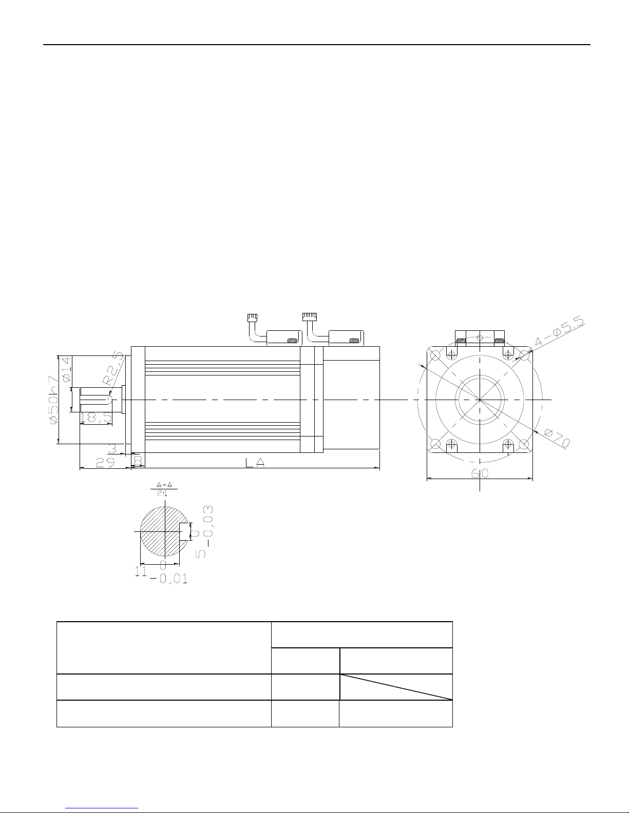
60 series motor installation dimensions Unit: mm
Type
LA
Normal
With brake
MS-60ST-M00630□□-20P2
110
MS-60ST-M01330□□-20P4
141
189
17
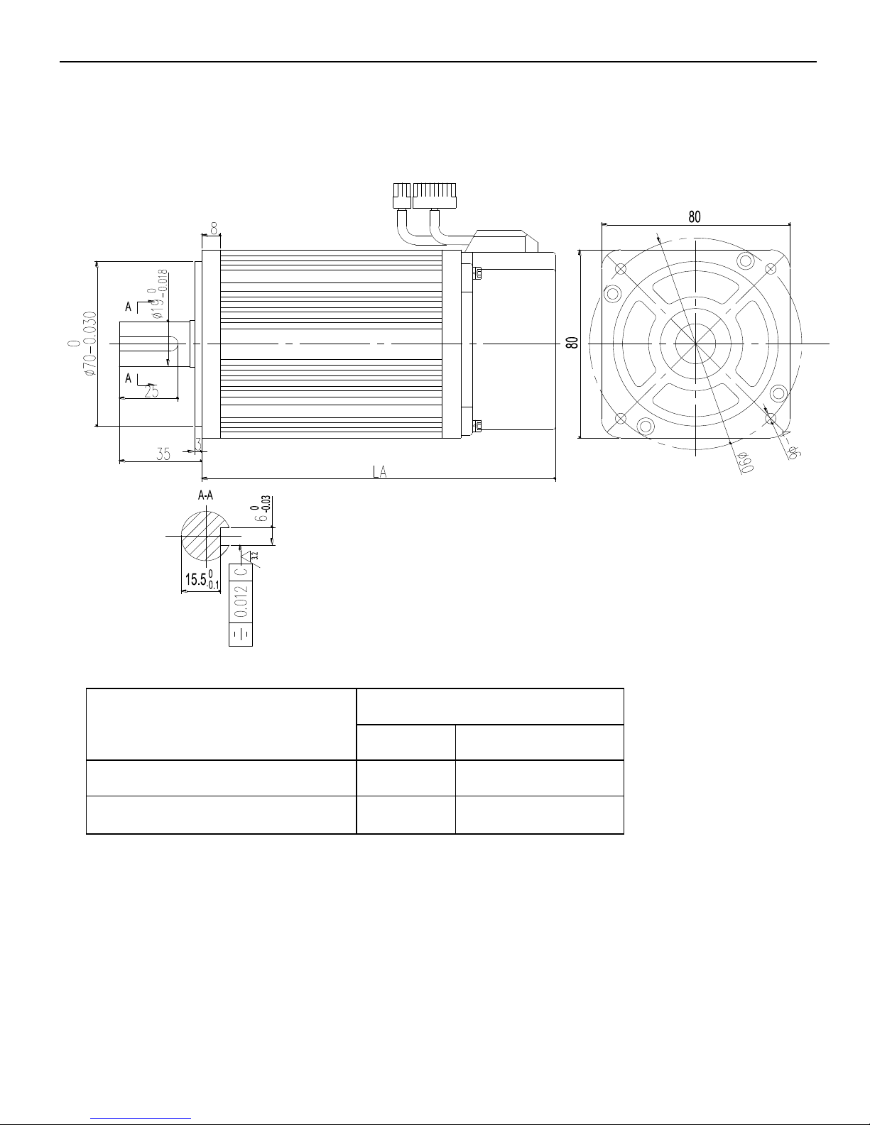
80 series motor installation dimensions Unit: mm
Type
LA
Normal
With brake
MS-80ST-M02430□□-20P7
150
191
MS-80ST-M03520□□-20P7
178
219
18
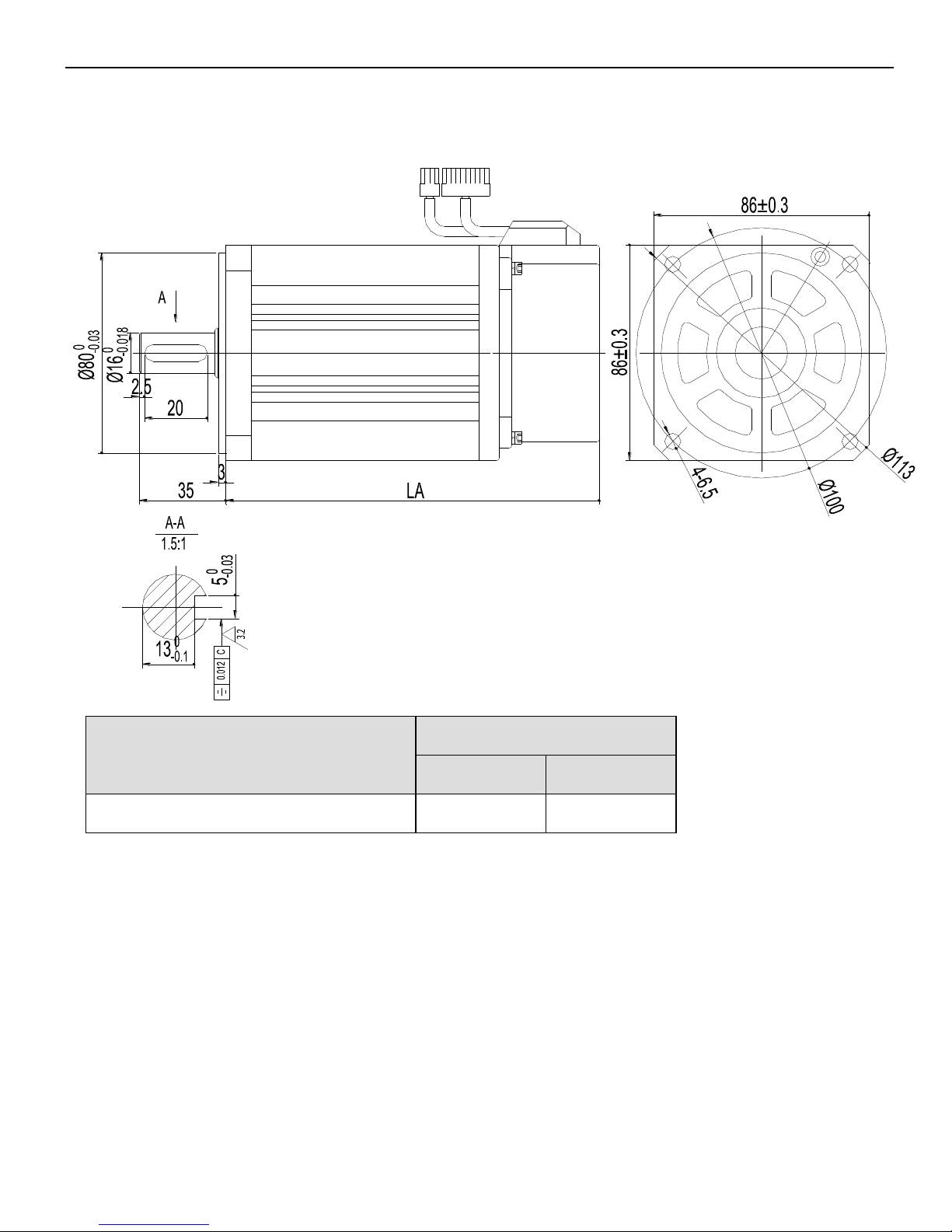
90 series motor installation dimensions Unit: mm
Type
LA
Normal
With brake
MS-90ST-M02430□□-20P7
149
194
19
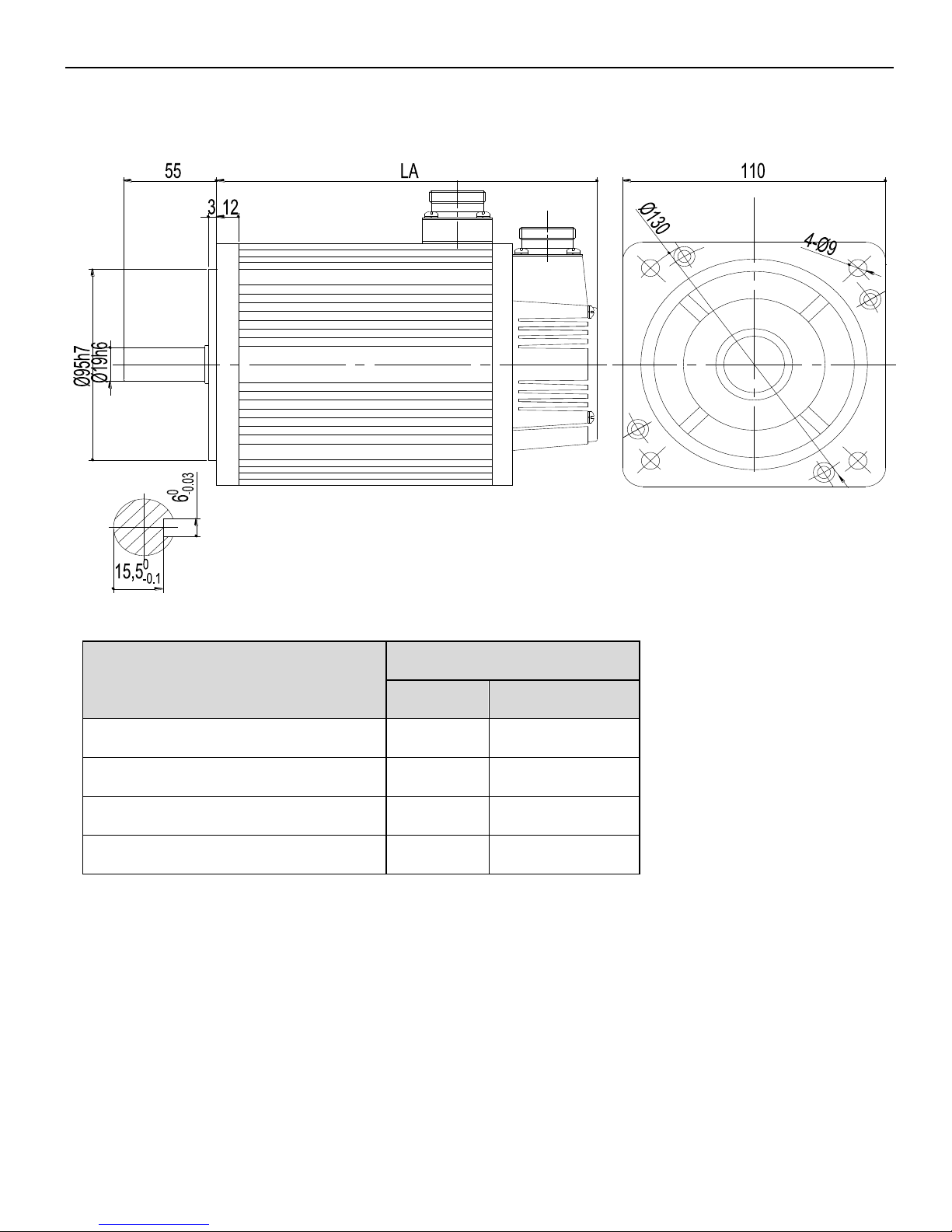
110 series motor installation dimensions Unit: mm
Type
LA
Normal
With brake
MS-110ST-M04030□□-21P2
189
263
MS-110ST-M05030□□-21P5
204
278
MS-110ST-M04030□□-41P2
189
263
MS-110ST-M05030□□-41P5
204
278
 Loading...