


XY40EV
SERVICE MANUAL
NOTICE
This manual was produced by the XINGYUN Group primarily for use by XINGYUN
dealers and their qualified mechanics. It is not possible to include all the knowledge of
a mechanic in one manual, so it is assumed that anyone who uses this book to
perform maintenance and repairs on XINGYUN vehicle has a basic understanding of
the mechanical ideas and the procedures of vehicle repair. Repairs attempted by
anyone without this knowledge are likely to render the vehicle unsafe and unfit for
use.
XINGYUN Group is continually striving to improve all its models. Modifications and
significant changes in specifications or procedures will be forwarded to all authorized
XINGYUN dealers and will appear in future editions of this manual where applicable.
NOTE:
Designs and specifications are subject to change without notice.
IMPORTANT INFORMATION
Particularly important information is distinguished in this manual by the following
notations.
The Safety Alert Symbol means ATTENTION! BECOME ALERT!
YOUR SAFETY IS INVOLVED!
Failure to follow WARNING instructions could result in severe
injury or death to the vehicle operator, passenger, a bystander, or
a person checking or repairing the vehicle.
CAUTION: A CAUTION indicates special precautions that must be taken to
avoid damage to the vehicle.
NOTE: A NOTE provides key information to make procedures easier or
clearer.

CONTENTS
CHAPTER1 ……………………………………………………….General Information
CHAPTER2 ………………………………………….……………………Maintenance
CHAPTER3…………………………………….……….….…… ………… Electrical
CHAPTER4…………………………………………..…………………………Chassis
CHAPTER5………………………………………………….……………….Final Drive
CHAPTER6………………………………………………………………………Brakes
Never run an engine in an enclosed area. Carbon monoxide exhaust gas is

poisonous and can cause severe injury or death. Always start engines outdoors.
Gasoline is extremely flammable and explosive under certain conditions. Battery
electrolyte is poisonous. It contains sulfuric acid. Serious burns can result from
contact with skin, eyes or clothing. Always keep alert and wear protection.
Exhaust system components are very hot during and after use of UTV. Never service
when the engine is warm or hot. Escaping steam from cooling system or hot oil from
the machine can cause severe burns. The engine must be cool before service.
Crate of the UTV and parts in the UTV maybe have sharp edge, always pay attention
and wear protection.
CHAPTER 1 GENERALINFORMATION SERVICE MANUAL
CHAPTER 1 GENERAL PAGE. 1-
1
CHAPTER 1 GENERAL INFORMATION
The parts of different types/ variants/ versions maybe un-interchangeable, even some parts have
almost same appearance. Always refer to Parts Manual of each UTV model for spare parts
information and service.
1.1 IMPORTANT INFORMATION
1.2 V.I.N AND MOTOR SERIAL NUMBER
1.3 VEHICLE DIMENSIONS

CHAPTER 1 GENERALINFORMATION SERVICE MANUAL
CHAPTER 1 GENERAL PAGE. 1-
2
1.1 IMPORTANT INFORMATION
PREPARATION FOR REMOVAL PROCEDURES
1. Remove all dirt, mud, dust and foreign material before removal and disassembly.
2. Use proper tools and cleaning equipment.
3. When disassembling the machine, always keep mated parts together. Mated part must always be
reused or replaced as an assembly.
4. During machine disassembly, clean all parts and place them in trays in the order of disassembly.
This will speed up assembly and allow for the correct installation of all parts.
5. Keep all parts away from any source of fire.
REPLACEMENT PARTS
Use only genuine parts for all replacements. Use recommended oil and grease for all lubrication
jobs. Other brands may be similar in function and appearance, but inferior in quality.
LOCK WASHERS/PLATES AND COTTER PINS
Replace all lock washers/plates and cotter pins
after removal. Bend lock tabs along the bolt or
nut flats after the bolt or nut has been tightened
to specification.
BEARINGS AND OIL SEALS
Install bearings and oil seals so that the
manufacturer’s marks or numbers are visible.
When installing oil seals, apply a light coating of
lightweight lithium base grease to the seal lips.
Oil bearings liberally when installing, if
appropriate.
① oil seal
CAUTION:
Do not use compressed air to spin the bearings
dry. This will damage the bearing surfaces.
① Bearing
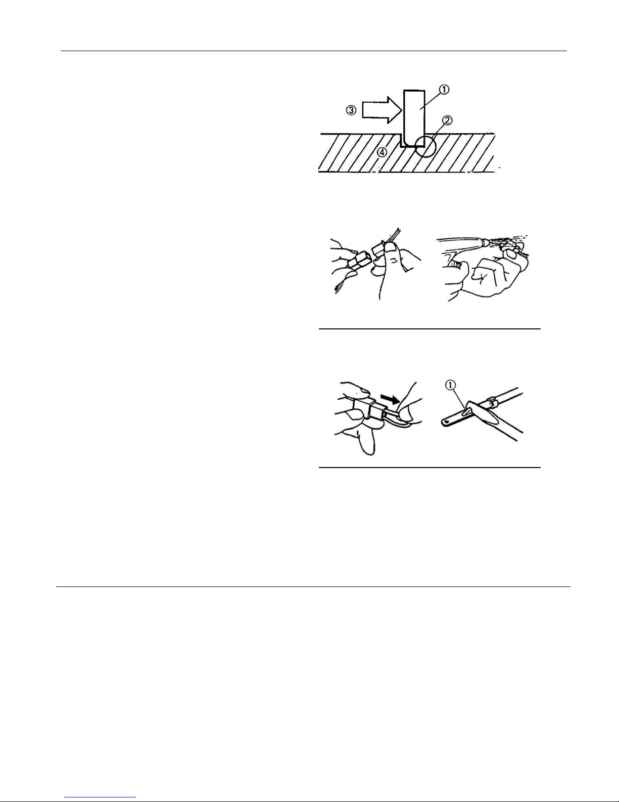
CIRCLIPS
1. Check all circlips carefully before reassembly.
Always replace piston pin clips after one use.
Replace distorted circlips. When installing a
circlip① , make sure that the sharp-edged
corner ② is positioned opposite the thrust
③ it receives. See sectional view.
④Shaft
CHAPTER 1 GENERALINFORMATION SERVICE MANUAL
CHAPTER 1 GENERAL PAGE. 1-
3
CHECKING OF CONNECTIONS
Dealing with stains, rust, moisture, etc. on the
connector.
1. Disconnect:
Connector
2. Dry each terminal with an air blower.
3. Connect and disconnect the connector two or
three.
4. Pull the lead to check that it will not come off.
5. If the terminal comes off, bend up the pin ①
and reinset the terminal into the connector.
6. Connect:
Connector
NOTE:
The two connectors ” click ” together.
7. Check for continuity with a tester.
NOTE:
If there is no continuity, clean the terminals.
Be sure to perform the steps 1 to 7 listed
above when checking the wire harness.
Use the tester on the connector as shown.

CHAPTER 1 GENERALINFORMATION SERVICE MANUAL
CHAPTER 1 GENERAL PAGE. 1-
4
CONVERSION TABLE
How to use the CONVERSION TABLE
Use this table to convert METRIC unit data to IMPERIAL unit data.
Ex.
METRIC MULIPLIER IMP
**mm x 0. 3937 = **in
**cm x 0.03937 = **in
CONVERSION TABLE
METRIC TO IMP
Known
Multiplier
Result
Torque
m·kg
m·kg
cm·kg
cm·kg
7.233
86.794
0.0723
0.8679
ft·lb
In·lb
ft·lb
In·lb
Weight
kg g 2.205
0.03527
lb
oz
Distance
km/h
km
m
m
cm
mm
0.6214
0.6214
3.281
1.094
0.3927
0.03927
mph
mi
ft
yd
in
in
Volume/
Capacity
cc(cm3)
cc(cm3)
lit(liter)
lit(liter)
0.03527
0.06102
0.8799
0.2199
oz(IMP liq.)
cu·in
qt (IMP liq.)
gal(IMP liq.)
Miscellaneous
kg/mm
kg/cm2
Centigrade
55.997
14.2234
9/5(℃)+32
lb/in
psi(lb/in2 )
Fahrenheit(°F)

CHAPTER 1 GENERALINFORMATION SERVICE MANUAL
CHAPTER 1 GENERAL PAGE. 1-
5
1.2 V.I.N AND MOTOR SERIAL NUMBER
The vehicle identification number ① is stamped
into the left side of the rear frame tube.
The motor serial number ② is stamped into left
side of motor crankcase.
CHAPTER 1 GENERALINFORMATION SERVICE MANUAL
CHAPTER 1 GENERAL PAGE. 1-
6
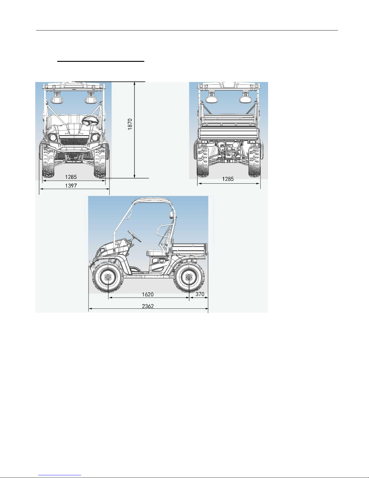
1.3 VEHICLE DIMENSIONS
Note.
The on-road equipments (rear view mirror, turn lights, etc.) are not Standard Equipment for USA.

CHAPTER 1 GENERALINFORMATION SERVICE MANUAL
CHAPTER 1 GENERAL PAGE. 1-
7
NOTES

CHAPTER 2 MAINTENANCE SERVICE MANUA
CHAPTER 2 MAINTENANCE PAGE. 2-
1
CHAPTER 2 MAINTENANCE
CAUTION
Due to the nature of the adjustments marked with a D on the following chart, it is recommended
that service be performed by an authorized dealer.
More often under severe use, such as dirty or wet conditions to purge water or dirt
contamination from grease fittings and other critical components.
PERIODIC MAINTENANCE SCHEDULE
Careful periodic maintenance will help keep your vehicle in the safest, most reliable condition.
Inspection, adjustment and lubrication intervals of important components are explained in the
following chart on the following pages.
NOTE:
Maintenance intervals are based upon average riding conditions and an average vehicle speed
of approximately 16 km/ 10 miles per hour. However, keep in mind that if the vehicle isn’t used
for a long period of time, the month maintenance intervals should be followed.
Vehicles subjected to severe use, such as operation in wet or dusty areas, should be inspected
and serviced more frequently.
Inspect, clean, lubricate, adjust or replace parts as necessary.
NOTE:
Inspection may reveal the need for replacement parts. Always use genuine parts available from
your dealer.
Service and adjustments are critical. If you are not familiar with safe service and adjustment
procedures, have a qualified dealer perform these operations.
CHAPTER 2 MAINTENANCE SERVICE MANUA
CHAPTER 2 MAINTENANCE PAGE. 2-
2
Item
Hours
When
Remarks
Brake System
Pre-ride
Pre-ride
Pre-ride inspection item
Electronic Accelerator
pedal
Pre-ride
Pre-ride
Pre-ride inspection item
Tires
Pre-ride
Pre-ride
Inspect daily, pre-ride inspection
item
Front and Rear Wheels/
Hubs
Pre-ride
Pre-ride
Pre-ride inspection item
Steering
Pre-ride
Pre-ride
Inspect daily, lubricate
D
Wheels bearings
10 hrs
Monthly
Check for looseness/ damage.
Replace if damaged.
Frame nuts, bolts
fasteners
Pre-ride
Pre-ride
Pre-ride inspection item
Headlamp Inspection
Daily
Daily
Check operation daily; apply
dielectric grease to connector
when replaced
Tail/ indicator lamp
inspection
Daily
Daily
Check operation daily; apply
dielectric grease to socket when
replaced
Air Filter-Main Element
Weekly
Weekly
Inspect –Replace if necessary
Transmission Oil Level
20 hrs
Monthly
Inspect monthly; change
annually
Battery
Monthly
Monthly
Check/clean Terminals; Check
damage and deformation
D
Brake pad wear
10 hrs
Monthly
Inspect periodically
Rear Gear case Oil
100 hrs
Monthly
Check monthly and change
annually
General Lubrication
50 hrs
3 months
Lubricate all fittings,
pivots, cables, etc.
D
Throttle Cable/
Accelerator pedal
20 hrs
monthly
Inspect –adjust, lubricate,
replace if necessary; pre-ride
inspection item
D
Steering system
50 hrs
6 months
Check operation and for
looseness, worn, damage,
binding feeling / Adjust, repair,
Replace if necessary.
Check toe alignment /Adjust if
necessary.
D
Front Axle
10 hrs
Monthly
Check for/ Bearing seals/
looseness/ damage.
Rear Axle
50 hrs
6 months
Inspect bearings, Lube
Front Prop Shaft&Shaft
Yoke
50 hrs
6 months
Check for looseness/ damage.

CHAPTER 2 MAINTENANCE SERVICE MANUA
CHAPTER 2 MAINTENANCE PAGE. 2-
3
Rear Prop Shaft, Shaft
Yoke & Boots
50 hrs
6 months
Check for/ boots/ looseness/
damage.
Front Suspension
50 hrs
6 months
Inspect-lubricate,
tighten fasteners
Rear Suspension
50 hrs
6 months
Inspect, tighten fasteners
D
Brake fluid
200 hrs
24
months
Change every two years
Headlight Aim
As
required
As
required
Adjust if necessary
Car charger
Monthly
Monthly
Check for heat/ cleanliness
Avoid water entry
LUBRICATION RECOMMENDATIONS
Item
Lube Rec
Method
Frequency
2.Brake Fluid
DOT 3 Only
Maintain level
Between fill lines. See
“7.CONTROL”
As require;
change
every two years
or 200 hours
3.Transmission Oil
SAE
80W/90GL5
Add to proper
level on dipstick
Change annually
or at
100 hours
Item
Lube Rec
Method
Frequency
6.Steering system
Grease
Lubricate the pivoting
and sliding parts
Every 3 months
or 50 hours
7.Tie rods
Grease
Grease
Semi-annually
8.Shift
Linkages
Grease
Locate fittings
and Grease
Semi-annually
9.Front Wheel
bearings
Inspect
Inspect and replace
bearings if
necessary
Semi-annually
10.Ball joints
Grease
Inspect, Locate fittings
and Grease, or replace
it if necessary
Semi-annually
11.Prop Shaft & Shaft
Yoke, Spline Joint
Grease
Locate fitting and
Grease
Semi-annually
12.Rear Axle
Bearing
Grease
Grease
Every 3 months
or 50 hours

CHAPTER 2 MAINTENANCE SERVICE MANUA
CHAPTER 2 MAINTENANCE PAGE. 2-
4
NOTE:
1. More often under severe use, such as wet or dusty conditions .
2. Grease: Light weight lithium-soap grease.
3. Grease M:molybdenum disulfide(MoS2 ) grease(water resistant).
4. *When suspension action becomes stiff or after washing.
5. Hours are based on 10 mph(16Km/h) average.
PERIODIC MAINTENANCE RECORD
Use the following chart to record periodic maintenance work:
Maintenance
Interval
Performed
Servicing
Date
Servicing Dealer
or
Person
Remarks
First 5 Hrs
10 Hrs
15 Hrs
20 Hrs
25 Hrs
50 Hrs
75 Hrs
100 Hrs
CHAPTER 2 MAINTENANCE SERVICE MANUA
CHAPTER 2 MAINTENANCE PAGE. 2-
5
The following items should be checked occasionally for tightness; or if they have been loosened
for maintenance service.
WHEEL NUT TORQUE SPECIFICATIONS
Bolt Size
Specification
M12X1.25
50Ft.Lbs
69N.m
NOTE: All nuts that have a cotter pin installed must be serviced by an authorized Dealer.
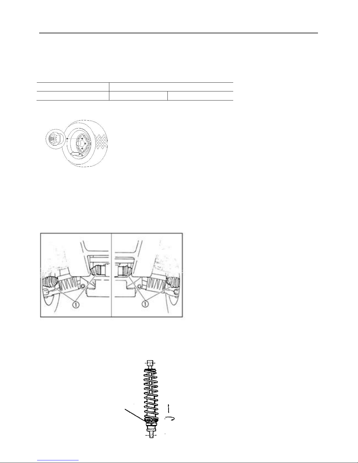
Rear Tapered nuts: install with tapered side against wheel
AXLE BOOTS
●Front Shaft Boots,
●Rear Axle (CV Joints,) Boots,
Check the protective boots for holes or tears. If any damage is found, have them replaced by an
authorized dealer.
REAR SPRING ADJUSTMENT
The rear shock absorber spring is adjusted by rotating the adjuster in the direction required to
increase or decrease spring tension.
Rear Spring
Adjustment
CHAPTER 2 MAINTENANCE SERVICE MANUA
CHAPTER 2 MAINTENANCE PAGE. 2-
6
STEERING
Steering Inspection
The steering assembly of the machine should be checked periodically for loose nuts and bolts,
worn tie rod ends, worn boots, and damage. Checking routing of all cables, hoses, and wiring to
be sure the steering mechanism is not restricted or limited. If any found, have your dealer repair
them before riding your vehicle.
The steering assembly should be also checked periodically for free operation, steering should
move freely through entire range of travel without binding. Park on level ground. Turn the
steering wheel right and left. Check for excessive free play, abnormal noises, or a rough feeling.
Have an authorized dealer repair as necessary for proper operation.
Lubricate the pivoting parts.
Recommended lubricant:
Lithium-soap-based grease
CAMBER AND CASTER
The camber and caster are non-adjustable.
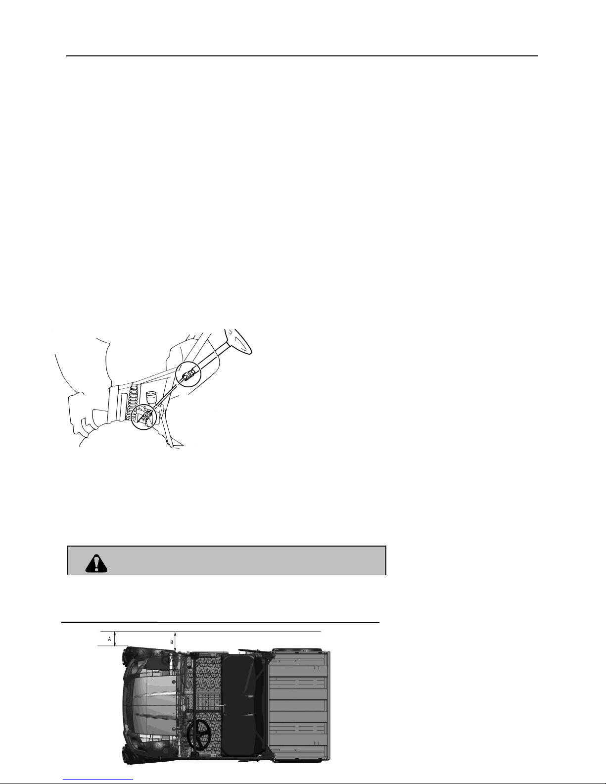
TOE ALIGNMENT CHECK
WARNING
Do not attempt to adjust the tie rod for toe alignment. Severe injury or death can result from
improper adjustment.
Contact your dealer. He/she has the training and tools to Make these adjustment.
CHAPTER 2 MAINTENANCE SERVICE MANUA
CHAPTER 2 MAINTENANCE PAGE. 2-
7
The recommended toe alignment is 1/8”to 1/4”(3to6mm) toe out.
1. Set the steering wheel in a straight ahead position and hold them in this position.
2. Measure A and B, B minus A should be 1/16” to 1/8” (1.5 to 3mm).
3. If this measurement needs to be adjusted, contact your dealer for service.
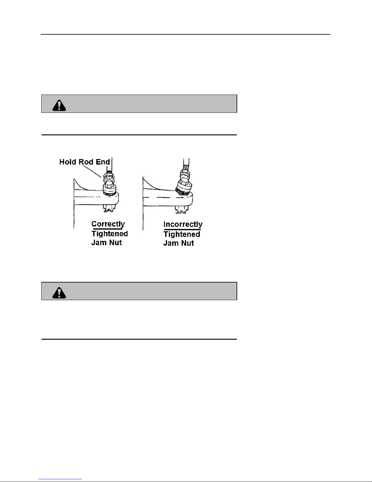
WARNING
If the tie rod is positioned incorrectly or adjusted incorrectly, it will not pivot, may break, and may
separate. Severe injury or death can result
BRAKES
Front brake
WARNING
Once a bottle of brake fluid is opened, use what is necessary and discard the rest. Do not
store or use a partial bottle of brake fluid. Brake fluid is hygroscopic, meaning it rapidly
absorbs moisture from the air. This causes the boiling temperature of the brake fluid to drop,
which can lead to early brake fade and the possibility of serious injury.
The front brake is hydraulic disc brakes which is depressing the brake pedal. These brakes are
self-adjusting and require no adjustment.
The following checks are recommended to keep the brake system in good operating condition.
How often they need checking depends upon the type of driving that has been done.
Keep fluid level in the master cylinder reservoirs as described see “7.Control and part
functions”. Normal functioning of the diaphragm is to extend into the reservoir as fluid lever
drops. If the fluid lever is low and the diaphragm is not extended, a leak is indicated and the
diaphragm should be replaced. Always fill the reservoir as indicated whenever the cover is
loosened or removed to insure proper diaphragm operation. Use DOT 3 brake fluid.
Check brake system for fluid leaks.
CHAPTER 2 MAINTENANCE SERVICE MANUA
CHAPTER 2 MAINTENANCE PAGE. 2-
8
Check brake for excessive travel
or spongy feel.
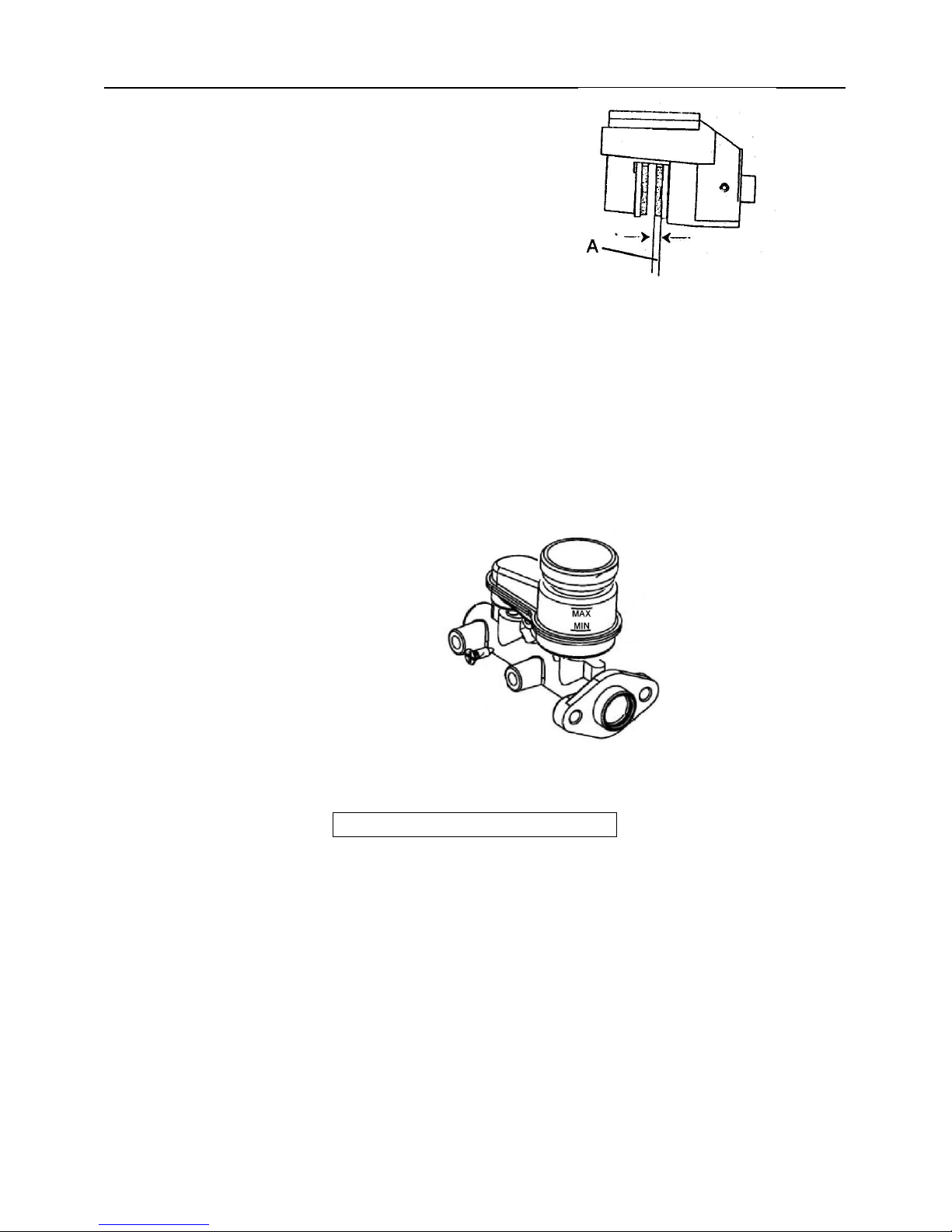
Check friction pads for wear,
damage and loosened.
Check security and surface
condition of the disc.
Pads should be changed when
friction material is worn to 3/64”(1mm).(A)
Rear Brake
The rear brake is a hydraulic disc type brake which is activated by the same pedal which
activates the front brake system is self adjusting and requires no maintenance other than
periodic checks of the pads for wear
Pads should be changed when the friction material is worn to 3/64”(1mm).
Inspect the brake disc and pad wear surface for excessive wear.
Checking the brake fluid level
Insufficient brake fluid may let air enter the brake system,
possibly causing the brakes to become ineffective. Before
riding, check that the brake fluid is above the minimum level
mark and replenish if necessary. A low brake fluid level may
indicate worn brake pads and/or brake system leakage. If
the brake fluid level is low, be sure
to check the brake pads for wear and the brake system for
leakage.
The brake fluid reservoir is located under the hood.
When checking the fluid level, make sure the top of
the brake fluid reservoir is level.
Use only the recommended quality brake fluid. Otherwise, the rubber seals may deteriorate,
causing leakage and poor braking performance.
Recommended brake fluid: DOT 3
Refill with the same type of brake fluid. Mixing fluids may result in a harmful chemical
reaction and lead to poor braking performance.
Be careful that water does not enter the brake fluid reservoir when refilling. Water will
significantly lower the boiling point of the fluid and may result in vapor lock.
Brake fluid may deteriorate painted surfaces or plastic parts. Always clean up spilled fluid
immediately.
Have an authorized dealer inspect the brake system if the brake fluid level goes down.
CHAPTER 2 MAINTENANCE SERVICE MANUA
CHAPTER 2 MAINTENANCE PAGE. 2-
9
LIGHTS
WARNING
Keep your headlights and taillights clean. Poor light while riding can result in an accident
causing severe injury or death.
CAUTION
Do not service while headlight is hot. Serious burns may result.
Do not touch a halogen lamp with bare fingers. Oil from your skin leaves a residue, causing a
hot spot which will shorten the life of the lamp.
Headlight Lamp Replacement
1. Use bulb 12V 35W/35W.
2. Pull the cable plug off the conducting
strip in the socket, remove the clip before
dismounting the bulb.
3. Fit a new bulb into the socket, sitting
properly in the three slots, install the
clip as shown in the fig. and connect
the cable plug to the conducting strip.
4. Change the bulb.
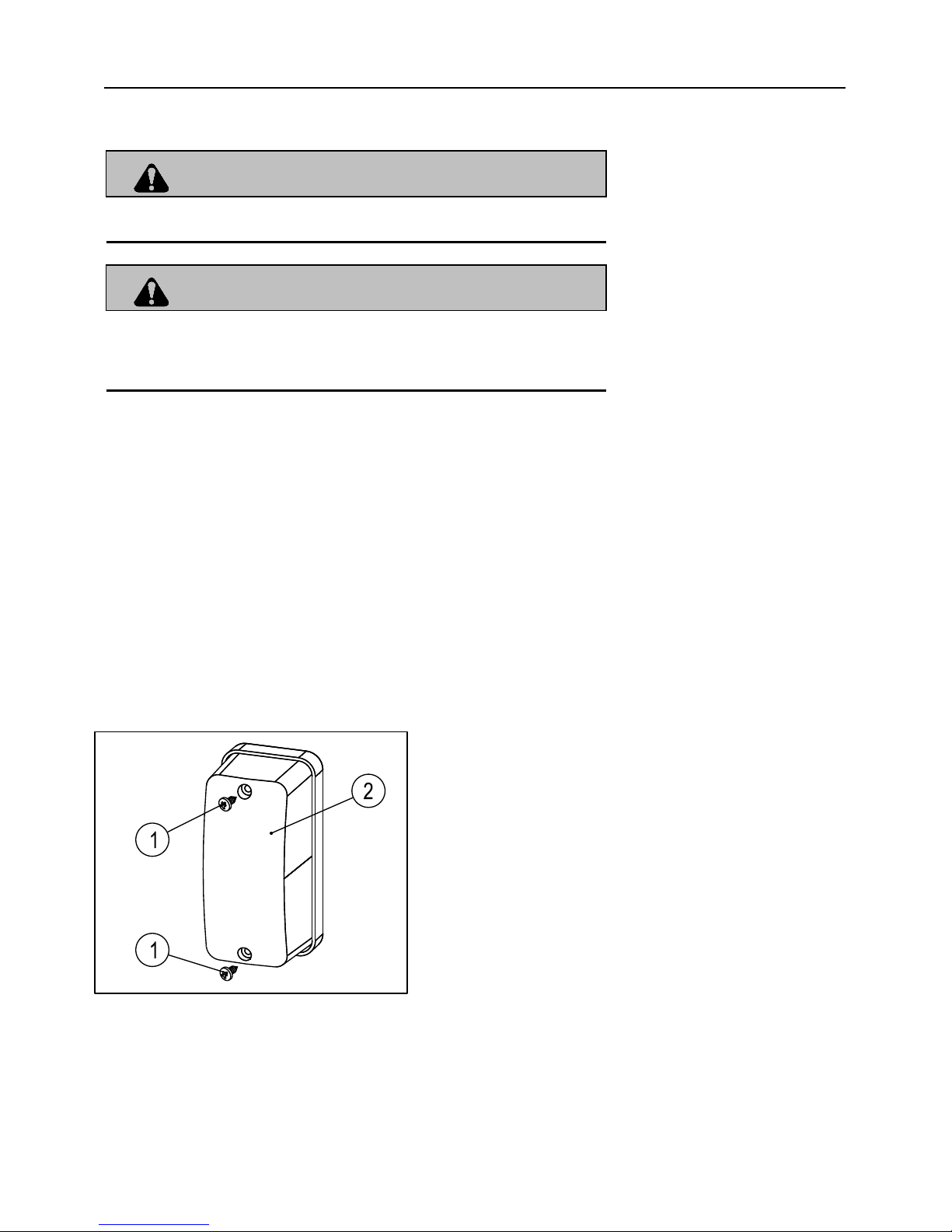
Taillight / Brake light Lamp Replacement
If the taillight / brake light does not work the lamp may need to be replaced.
1. Screw
2. Lens
1. Remove the screws①.
2. Remove the lens②.
3. Remove bulb and replace it with recommended
bulb.
4. Test the taillight/ brakelight to see that it’s working .
5. Reinstall the lens and screws.

CHAPTER 2 MAINTENANCE SERVICE MANUA
CHAPTER 2 MAINTENANCE PAGE. 2-
10
High Beam Headlight Adjustment
The headlight beam can be adjusted up and down.
1. Place the vehicle on a
level surface with the headlight
approximately 10’’(3m) from a wall.
2. Measure the distance from the
floor to the center of the headlight
and make a mark on the wall at the
same height.
3. Start the engine and turn the headlight switch to high beam.
4. Observe headlight aim. The most intense part of the headlight beam should be aimed 2.8’’
(71mm) below the mark placed on the wall in step 2. NOTE : Driving weight must be
included on the seat.
5. To turn the two adjusting screws ③ clockwise is to lower the beam area and
to turn the two adjusting screws ③ counterclockwise is to heighten the beam area.

CHAPTER 3 ELECTRICAL
3.1 PARTS INSPECTION AND SERVICE
3.2 BATTERY
3.3 Drive System
3.4 Drive System Common Malfunction
3.5 LIGHTING SYSTEM
3.6 LCD Meter
3.7 WIRING DIAGR
3.1 PARTS INSPECTION AND SERVICE
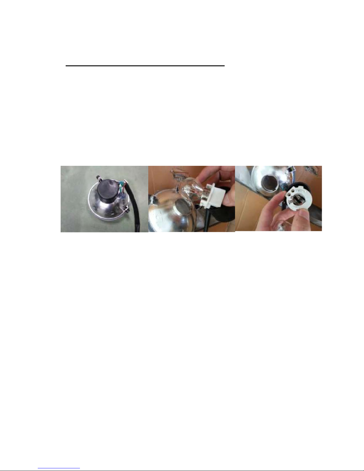
HEADLIGHT ADJUSTMENT
1. Use bulb 12V 35W/35W.
2. Remove the black sheath, turning the
socket counterclockwise and take
it out. Turning the bulb counterclockwise
and Remove it from the socket.
3. Change the bulb.
HEADLIGHT ADJUSTMENT
1. The headlight beam can be adjusted vertically.
2. Place the vehicle on a level surface with the headlight approximately
33in(10m) from a wall.
3. Measure the distance from the floor to the center of the headlight and
make a mark on the wall at
the same height.
4. Start the engine and turn the headlight switch to high beam.
5. Observe headlight aim. The most intense part of the headlight beam
should be aimed 86mm to
129mm below the mark placed on the wall in step 2. NOTE : Riding
weight must be included on
the seat.
6. Loosen but not remove pivot bolt/ screw and adjust beam to desired
 Loading...