

Xineron HNG-D312S Quick Installation Manual

HNG-D312S, Quick Installation Guide
1. Description
This manual applies to the Plastic Dome Network Camera.
The Network Camera supports the network service for a sensor image with progressive scan, which
can be monitored on a real-time screen regardless of distances and locations. By using its dedicated
program, many users are able to have an access to the Network Camera at once or a single user can
monitor various network cameras at the same time. It also enables users to play, store and retrieve a
monitoring image by using a PC. All the settings and real-time monitoring screens are also provided
through an access to the web.
The Network Camera is fully featured for security surveillance and remote monitoring needs. It is
based on the DSP compression chip, and makes it available on the network as real-time, full frame
rate Motion JPEG and H.264 (or MPEG-4) video streams.
The alarm input and alarm output can be used to connect various third party devices, such as, door
sensors and alarm bells.
• Installation Steps
Follow these steps to install the Network Transmitter on your local network (LAN):
1. Check the package contents against the list below.
2. Connect the Network Camera. See page 3.
3. Set an IP address. See page 4.
4. Set the password. See page 6.
• Package Component
The system comes with the following components:
Camera unit Installation CD Installation Guide Template Sheet Accessory Kit
• Contents in the installation CD
1. The Network Camera User’s Manual
2. The NautilusClient16 User’s Manual
3. The Nautilus Server User’s Manual
4. The NautilusClient16 Installation software
5. The Nautilus Server Installation software
Note: Check your package to make sure that you received the complete system, including all
components shown above.
HNG-D312S, Quick Installation Guide
2
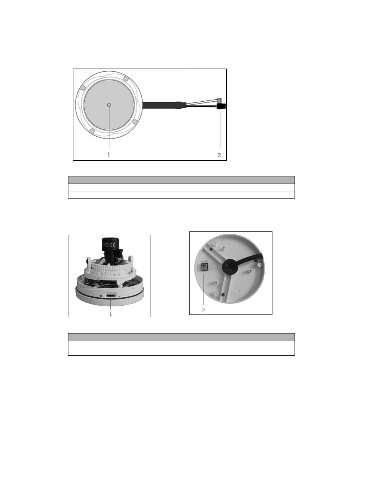
• Top View
NO
Name
Description
1
Lens
Allows wide area to be monitored
2
Extension Cable
26pin camera extension cable
• Side View • Bottom View
NO
Name
Description
1
Micro SD Slot
Micro SD slot for local recording
2
Alarm IO Terminal
AI: Alarm Input, G: Ground, AO: Alarm Output

HNG-D312S, Quick Installation Guide
3
• Extension Cable
NO
Wire Color
Description
1
Red: DC12V
White: GND
Main Power, 2pin terminal, DC12V, max. 4.0W
2
Black
Ethernet, RJ-45 port compatible with 10/100Mbps PoE.
Modular Jack
2. Installation
2.1 Connection
• Connecting to the RJ-45
Connect a standard RJ-45 cable to the network port of the network camera. Generally a
cross-over cable is used for directly connection to PC, while a direct cable is used for connection
to a hub.
• Connecting Alarms
AI(Alarm In) :
You can use external devices to signal the network camera to react on events. Mechanical or
electrical switches can be wired to the AI (Alarm In) and G (Ground) connectors in the bottom.
G(Ground) :
Connect the ground side of the alarm input and/or alarm output to the G (Ground) connector.
Alarm Out :
The network camera can activate external devices such as buzzers or lights. Connect the device
to the AO (Alarm Out) and G (Ground) connectors.
• Connecting Video Output
Video Output is used for an easy zoom and focus control
when installing lens.
Connect your Video cable unit to J5 on the board.
• Connecting the Power
Connect the power of DC12V 0.35A for the network camera. Connect the positive(+) pole to the
‘+’ position and the negative(-) pole to the ‘-‘ position.
Use certified / Listed Class 2 power source only.
 Loading...