

Xineron HDB-T302 Instruction Manual
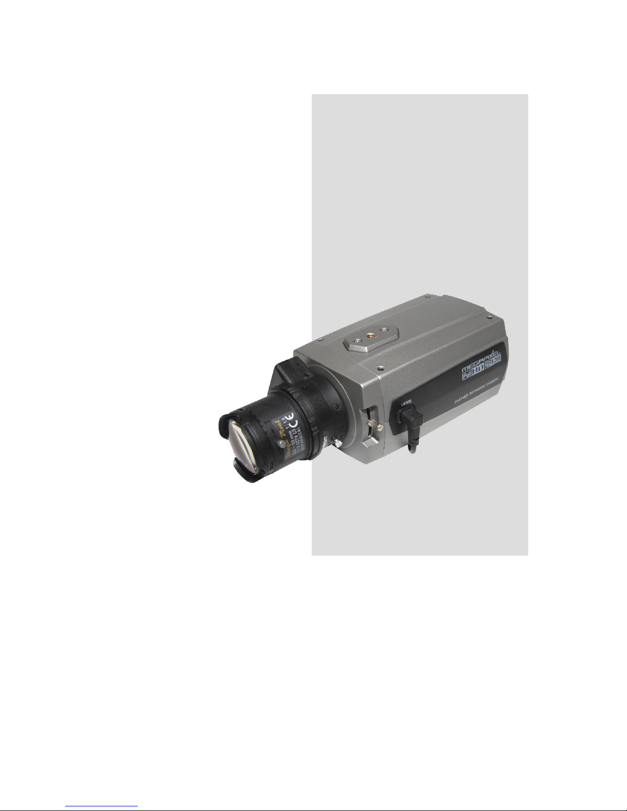
Full-HD NETWORK
BOX CAMERA
INSTRUCTION MANUAL
Please read this manual thoroughly before use, and keep it handy for future reference.

2
WARNING
TO REDUCE THE RISK OF FIRE OR ELECTRIC SHOCK, DO NOT EXPOSE THIS PROCUCT TO
RAIN OR MOISTURE. DO NOT INSERT ANY METALLIC OBJECT THROUGH THE VENTILATION
GRILLS OR OTHER OPENNINGS ON THE EQUIPMENT.
CAUTION
EXPLANATION OF GRAPHICAL SYMBOLS
The lightning flash with arrowhead symbol, within an equilateral triangle, is intended to alert the user
to the presence of uninsulated "dangerous voltage" within the product’s enclosure that may be of
sufficient magnitude to constitute a risk of electric shock.
The exclamation point within an equilateral triangle is intended to alert the user to the presence of
important operating and maintenance (servicing) instructions in the literature accompanying the
appliance.
PRECAUTIONS
Safety -------------------------------------- Installation -------------------------------
Should any liquid or solid object fall into the cabinet,
unplug the unit and have it checked by the qualified
personnel before operating it any further.
Unplug the unit from the wall outlet if it is not going to
be used for several days or more. To disconnect the
cord, pull it out by the plug. Never pull the cord itself.
Allow adequate air circulation to prevent internal heat
build-up. Do not place the unit on surfaces (rugs,
blankets, etc.) or near materials(curtains, draperies)
that may block the ventilation holes.
Height and vertical linearity controls located at the rear
panel are for special adjustments by qualified
personnel only.
Do not install the unit in an extremely hot or humid
place or in a place subject to excessive dust,
mechanical vibration.
The unit is not designed to be waterproof.
Exposure to rain or water may damage the unit.
Cleaning ---------------------------------
Clean the unit with a slightly damp soft cloth.
Use a mild household detergent. Never use strong
solvents such as thinner or benzene as they might
damage the finish of the unit.
Retain the original carton and packing materials for
safe transport of this unit in the future.

3
FCC COMPLIANCE STATEMENT
INFORMATION TO THE USER: THIS EQUIPMENT HAS BEEN TESTED AND FOUND TO
COMPLY WITH THE LIMITS FOR A CLASS A DIGITAL DEVICE, PURSUANT TO PART 15 OF THE FCC
RULES. THESE LIMITS ARE DESIGNED TO PROVIDE REASONABLE PROTECTION AGAINST HARMFUL
INTERFERENCE WHEN THE EQUIPMENT IS OPERATED IN A COMMERCIAL ENVIRONMENT. THIS
EQUIPMENT GENERATES, USES, AND CAN RADIATE RADIO FREQUENCY ENERGY AND IF NOT
INSTALLED AND USED IN ACCORDANCE WITH THE INSTRUCTION MANUAL, MAY CAUSE HARMFUL
INTERFERENCE TO RADIO COMMUNICATIONS.
CAUTION: CHANGES OR MODIFICATIONS NOT EXPRESSLY APPROVED BY THE PARTY
RESPONSIBLE FOR COMPLIANCE COULD VOID THE USER'S AUTHORITY TO OPERATE THE
EQUIPMENT.
THIS CLASS A DIGITAL APPARATUS COMPLIES WITH CANADIAN ICES-003.
CET APPAREIL NUMÉRIQUE DE LA CLASSE A EST CONFORME À LA NORME NMB-003 DU CANADA.
CE COMPLIANCE STATEMENT
WARNING: This is a Class A product. In a domestic environment this product may cause radio
interference in which case the user may be required to take adequate measures.

4
IMPORTANT SAFETY INSTRUCTIONS
1. Read these instructions.
2. Keep these instructions.
3. Heed all warnings.
4. Follow all instructions.
5. Do not use this apparatus near water.
6. Clean only with dry cloth.
7. Do not block any ventilation openings. Install in accordance with the manufacturer’s
instructions.
8. Do not install near any heat sources such as radiators, heat registers, stoves, or other
apparatus (including amplifiers) that produce heat.
9. Do not defeat the safety purpose of the polarized or grounding-type plug. A polarized plug has
two blades with one wider than the other. A grounding type plug has two blades and a third
grounding prong. The wide blade or the third prong are provided for your safety. If the
provided plug does not fit into your outlet, consult an electrician for replacement of the
obsolete outlet.
10. Protect the power cord from being walked on or pinched particularly at plugs, convenience
receptacles, and the point where they exit from the apparatus.
11. Only use attachments/accessories specified by the manufacturer.
12. Use only with the cart, stand, tripod, bracket, or table specified
by the manufacturer, or sold with the apparatus. When a cart is
used, use caution when moving the cart/apparatus combination
to avoid injury from tip-over.
13. Unplug this apparatus during lightning storms or when unused
for long periods of time.
14. Refer all servicing to qualified service personnel. Servicing is
required when the apparatus has been damaged in any way,
such as power-supply cord or plug is damaged, liquid has been
moisture, does not operate normally, or has been dropped.
15. CAUTION – THESE SERVICING INSTRUCTIONS ARE FOR USE BY QUALIFIED
SERVICE PERSONNEL ONLY. TO REDUCE THE RISK OF ELECTRIC SHOCK DO
NOT PERFORM ANY SERVICING OTHER THAN THAT CONTAINED IN THE
OPERATING INSTRUCTIONS UNLESS YOU QRE QUALIFIED TO DO SO.
16. Use satisfy clause 2.5 of IEC60950-1/UL60950-1 or Certified/Listed Class 2
power source only.
17. ITE is to be connected only to PoE networks without routing to the outside plant.

5
Contents
1. Description ------------------------------------------------------------------ 7
1.1 Components -- ------------------------------------------------------------------------------------------- 7
1.2 Key Features - ------------------------------------------------------------------------------------------- 8
1.3 Over View----- ------------------------------------------------------------------------------------------- 9
1.4 Camera Adjustment ------------------------------------------------------------------------------------- 10
2. Installation ----------------------------------------------------------------- 14
2.1 Network Connection ------------------------------------------------------------------------------------ 14
2.2 IP Assignment ------------------------------------------------------------------------------------------ 14
3. Operation -------------------------------------------------------------------- 16
3.1 Access from a browser --------------------------------------------------------------------------------- 16
3.2 Access from the internet ------------------------------------------------------------------------------- 17
3.3 Setting the admin password over a secure connection ------------------------------------------- 17
3.4 Live View Page ------------------------------------------------------------------------------------------- 18
3.5 Network Camera Setup --------------------------------------------------------------------------------- 20
3.5.1 Basic Configuration ----------------------------------------------------------------------------- 20
1) Users ------------------------------------------------------------------------------------------- 21
2) Network --------------------------------------------------------------------------------------- 22
3) Video & Image ------------------------------------------------------------------------------- 23
4) Audio ------------------------------------------------------------------------------------------- 25
5) Date & Time ---------------------------------------------------------------------------------- 27
3.5.2 Video & Image ----------------------------------------------------------------------------------- 28
3.5.3 Audio ----------------------------------------------------------------------------------------------- 34
3.5.4 Event ----------------------------------------------------------------------------------------------- 35
1) Event-In --------------------------------------------------------------------------------------- 35
2) Event-Out ------------------------------------------------------------------------------------- 40
3) Event Map ------------------------------------------------------------------------------------- 49
3.5.5 Device ---------------------------------------------------------------------------------------------- 50
1) PTZ------------- -------------------------------------------------------------------------------- 50
2) RS-485 ----------------------------------------------------------------------------------------- 51
3.5.6 System ------------------------------------------------------------------------------------------- 52
1) Information ----------------------------------------------------------------------------------- 52
2) Security ---------------------------------------------------------------------------------------- 53
3) Date & Time ---------------------------------------------------------------------------------- 56
4) Network --------------------------------------------------------------------------------------- 57
5) Language -------------------------------------------------------------------------------------- 66
6) Maintenance ---------------------------------------------------------------------------------- 67
7) Support ---------------------------------------------------------------------------------------- 68
3.5.7 About ----------------------------------------------------------------------------------------------- 68
3.6 Playback----------------------------------------------------------------------------------------------------69
3.7 Help ------------------------------------------------------------------------------------------------------- 71
3.8 Resetting to the factory default settings -------------------------------------------------------------- 72

6
4. Appendix -------------------------------------------------------------------- 73
4.1 Troubleshooting ------------------------------------------------------------------------------------------- 73
4.2 Alarm Connection ----------------------------------------------------------------------------------------- 74
4.3 Preventive Maintenance --------------------------------------------------------------------------------- 74
4.4 Product Specification ------------------------------------------------------------------------------------ 75
7
1. Description
This manual applies to the HDB-3x0 series network camera.
The Network Camera supports the network service for a sensor image with progressive scan, which
can be monitored on a real-time screen regardless of distances and locations. By using its dedicated
program, many users are able to have an access to the Network Camera at once or a single user can
monitor various network cameras at the same time. It also enables users to play, store and retrieve a
monitoring image by using a PC. All the settings and real-time monitoring screens are also provided
through an access to the web.
The Network Camera is fully featured for security surveillance and remote monitoring needs. It is
based on the DSP compression chip, and makes it available on the network as real-time, full frame
rate Motion JPEG and H.264 (or MPEG-4) video streams.
The alarm input and alarm output can be used to connect various third party devices, such as, door
sensors and alarm bells.
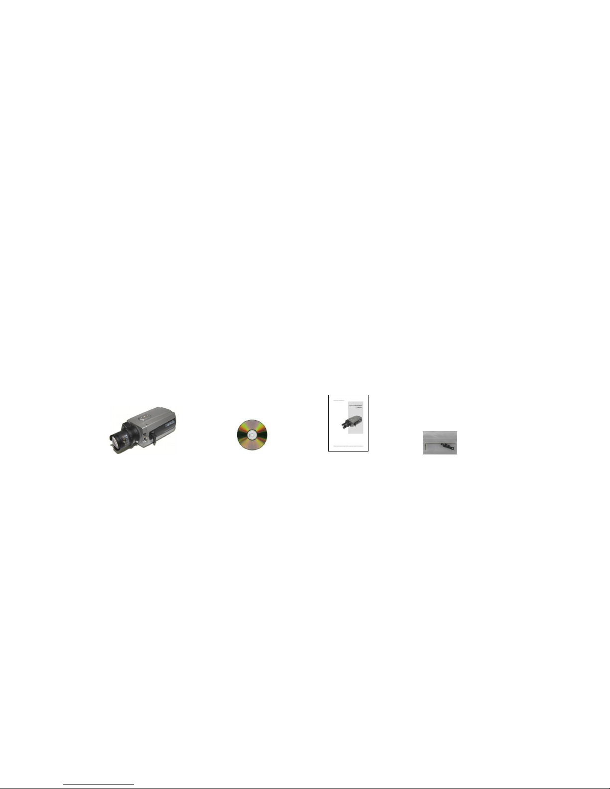
1.1 Components
The system comes with the following components:
Network Camera unit Installation CD Installation Guide Accessory Kit
NOTE: Check your package to make sure that you received the complete system, including all
components shown above.

8
1.2 Key Features
• Brilliant video quality
The Network Camera offers the highly efficient H.264 video compression, which drastically
reduces bandwidth and storage requirements without compromising image quality. Motion JPEG
is also supported for increased flexibility.
• Dual streams
The Network Camera can deliver dual video streams simultaneously at full frame rate in all
resolutions up to Full-HD(1920 x 1080p) using Motion JPEG and H.264 (or MPEG-4). This means
that several video streams can be configured with different compression formats, resolutions and
frame rates for different needs.
• Image setting adjustment
The Network Camera also enables users to adjust image settings such as contrast, brightness
and saturation to improve images before encoding takes place.
• Intelligent video capabilities
The Network Camera includes intelligent capabilities such as enhanced video motion detection.
The encoder’s external inputs and outputs can be connected to devices such as sensors and
relays, enabling the system to react to alarms and activate lights or open/close doors.
• Resolution
The Network Camera supports two kinds of resolutions according to the model name.
HDB-T302, HDB-T3x2 Series, 1 Megapixel, 30fps@1280x720
HDB-T322, HDB-T3x2 Series, 2 Megapixel, 30fps@1920x1080
• Micro-SD Recording support
The Network Camera also supports a micro-SD memory slot for local recording with removable
storage.
• Audio support
The Network Camera also supports two-way audio.
• Improved Security
The Network Camera logs all user access, and lists currently connected users. Also, its full frame
rate video can be provided over HTTPS.
• ONVIF
This is a global interface standard that makes it easier for end users, integrators, consultants,
and manufacturers to take advantage of the possibilities offered by network video technology.
ONVIF enables interoperability between different vendor products, increased flexibility, reduced
cost, and future-proof systems.
9
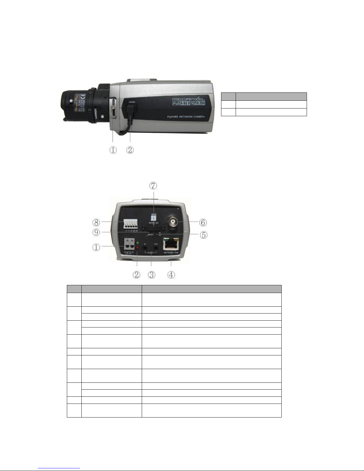
1.3 Overview
• Front View
NO
Function
1
Focus adjusting fixing screw
2
Auto IRIS lens connector
• Rear View
NO
Function
Description
1
Power Adaptor Terminal
Connects the supplied power adapter or an external
power supply 12V DC or 24V AC, max. 4.0Watt.
2
Power Indicator(Green)
Indicates power input.
Status Indicator(Red)
Indicates camera status.
3
Audio Input
Audio Input Stereo Jack
Audio Output
Audio Output Stereo Jack
4
Network Connector
(PoE)
RJ-45 port compatible with 10/100Mbps, which have a PoE
function.
5
Video Switch
Selects Video On/Off. Set to On to output a video signal.
6
Video Output
Connects the video output. This BNC connector
provides a 1.0Vp-p/75 ohms composite video signal.
7
Micro SD Card Slot
Card Slot for Micro SD. Open the protection cover
with a supported tool to insert Micro SD card.
8
3pin Terminal IO
Connects alarm In/Out.
2pin RS485 Terminal
Connects PT device.
9
Reset Button
Executes the factory default.
11
Video Output
Connects the video output. This BNC connector
provides a 1.0Vp-p/75 ohms composite video signal.

10
Note: Video Output is used for an easy zoom and focus control when installing lens. After lens
installation, you must set Video Switch to Off to provide the best performance of the
Network Camera.
• LED Indicators
LED
Color
Indication
Network
Green
Steady for connection to a 100 Mbit/s network. Flashes for
network activity.
Amber
Steady for connection to 10 Mbit/s network. Flashes for
network activity.
Unlit
No network connection.
Status
Red
Steady red for failed upgrade or booting.
Power
Green
Steady green for normal operation or booting.
Flashes green during firmware upgrade.
Note: Steady green and red during booting. Flash green and red during factory default.
1.4 Camera Adjustment
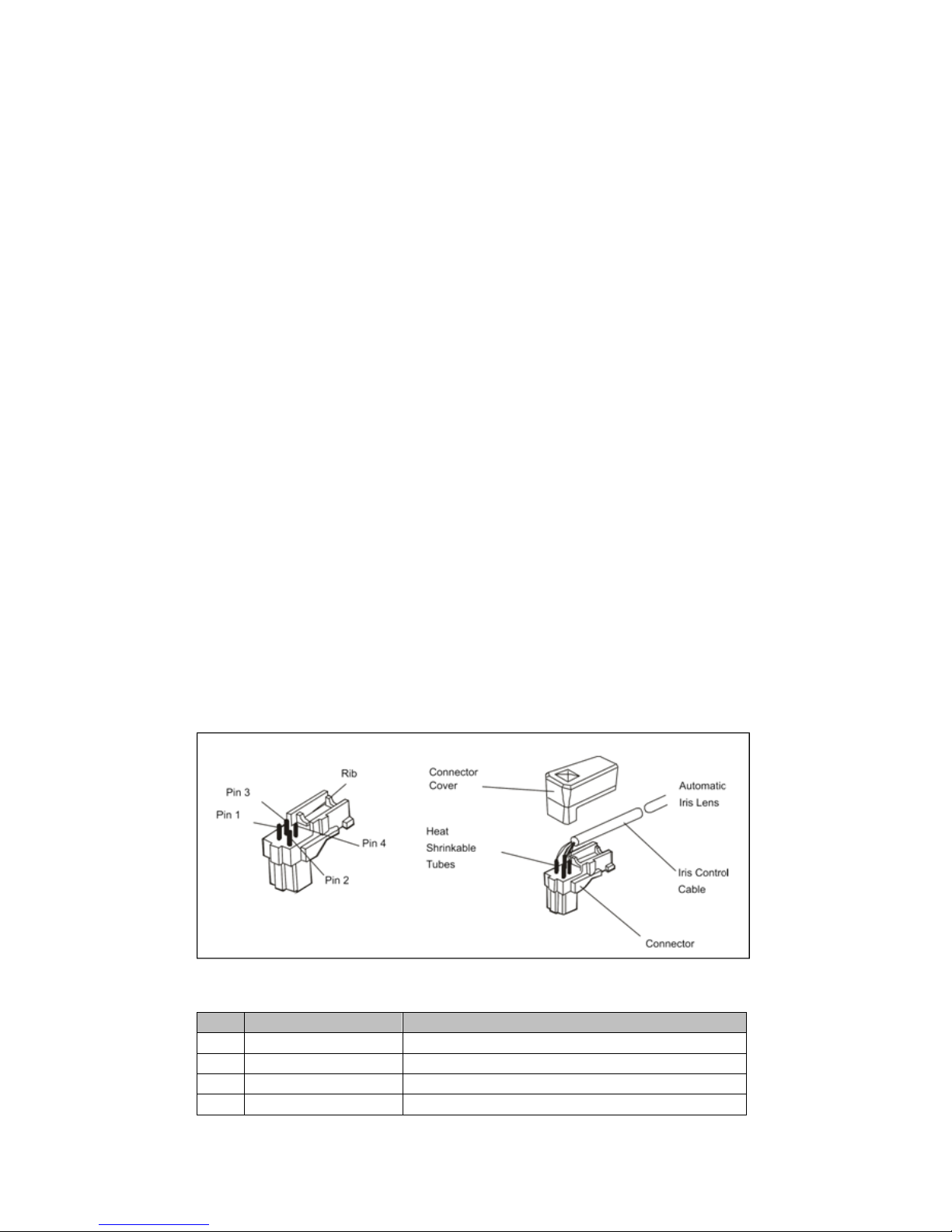
1) Video auto IRIS installation & adjustment
The camera supports video-type auto iris lenses which adjust to changing light levels.
Perform the following steps to install and adjust a video-type auto iris lens.
If necessary, solder the lens control wires to the connector supplied with the camera.
1. Attach the video-type auto iris lens to the lens mount on the front of the camera.
Pin
Name
Wire Color
1
Voltage +
Red
2
Open
- 3 Video
White
4
Ground
Black
11
2. IMPORTANT: The minimum Plug the connector from the lens into the auto iris jack on the
back of the camera. The connector is polarized and can only be inserted into the jack one
way.
3. Apply power to the camera.
4. The OSD AE menu in the lens select should be in the “VIDEO”.
5. Adjust the focus ring on the lens for an optimum picture. If a picture is not visible, set the
lens for proper exposure by adjusting the ALC (Automatic Level Control) and the level on the
lens. The ALC setting can range between AVG (average) or PK (peak). A midrange setting is
appropriate for most applications.
For ALC adjustments: AVG To slow the reaction of the lens to changing light, set the
range to the AVG setting to average the video level from the camera. Use when there are
bright spots in the picture such as lights or glare from the sun.
PK To increase the speed of the lens reaction to the changing light, set the lens adjustment
to PK so the lens will adjust to the brightest or peak object in the video. Use this setting if
you want to see the brightest object and not the background objects.
For Level adjustments: Adjust the level control for the best picture during the day. A
night adjustment may not provide the proper setting for controlling the light during the day.
6. Set the back focus of the camera before the final adjustment of the video level.
7. If the auto iris has a gain adjustment and the picture oscillates between open and closed
under bright lights, slowly turn the gain adjustment counter clockwise until the oscillating
stops. Increase the light getting to the camera by adjusting the level control and readjusting the gain control.
2) DC auto IRIS lens installation & adjustment
1. Solder the lens control wires to the connector supplied with the camera.
Pin
Name
Wire Color
1
Damp Coil -
Blue
2
Damp Coil +
Red
3
Drive Coil +
White
4
Drive Coil -
Green

12
2. Attach the DC-type auto iris lens to the lens mount on the front of the camera.
3. Plug the connector into the auto iris jack on the side of the camera. The connector is
polarized and can only inserted into the jack one way.
4. Apply power to the camera.
3) Manual IRIS lens adjustment
When using a manual iris lens, turn the iris ring on the lens to the OPEN position and adjust the
manual iris for the appropriate range. Adjust during the brightest conditions, opening the lens to
the minimum f-stop yielding a good picture under the brightest scene conditions. Do not saturate
the picture.
The manual iris is used in indoor applications where lighting from windows can considerably
affect the light level of the room.
4) Back Focus adjustment
For best results, perform back focus adjustments at night or while using a #6 or #8 welder's
glass in front of the lens. The focus of the camera will change slightly if the camera iris was
adjusted on a light scene, then changes to a dark scene. However, the camera will remain in
focus if the iris was focused on a dark scene and the scene lightens.
1. The lens should be mounted on the camera before applying power.
2. If a picture is visible, focus on the picture. If the picture is not visible, open the iris on the
lens. Open the lens as wide as possible by placing the welder's glass in front of the lens and
forcing the lens to automatically open.
3. When the iris is open to the widest point, re-adjust the focus for clear picture. If a clear
picture is not possible, set the focus ring to midrange.
4. Loosen the back focus lock screw.
5. Adjust the back focus ring for a clear picture.
6. Tighten the back focus lock screw.

13
7. Fine tune the focus with the focus ring on the lens.
8. Remove the welder's glass from in front of the lens.
9. Adjust the iris of the lens for the best picture quality.
5) Zoom lens back focus adjustment
The objective of back focusing a zoom lens is similar to that of a fixed focal length camera except
the back focus is also adjusted to maintain the focus when "zooming" the lens in and out on a
scene.
1. Choose an object at the farthest range set for viewing with a zoom lens.
2. Make sure the iris of the lens is wide open. Do this by adjusting the camera at night or use
a welders glass in front of the lens.
3. Adjust the focus to the stop on the far range.
4. Adjust the zoom on the lens to obtain the widest picture.
5. Loosen the back focus lock screw.
6. Adjust the back focus ring for the clearest picture.
7. Tighten the back focus lock screw.
8. Adjust the zoom on the lens to the far telephoto position.
9. Adjust the back focus ring for the clearest picture.
10. Adjust the zoom on the lens back to the widest picture.
11. Loosen the back focus screw.
12. Re-adjust the back focus for the clearest picture.
13. Tighten the back focus lock screw.
14. Repeat the previous steps as necessary to maintain a clear picture throughout the entire
zoom range.

14
2. Installation
2.1 Connection
• Connecting to the RJ-45
Connect a standard RJ-45 cable to the network port of the network camera. Generally a
cross-over cable is used for directly connection to PC, while a direct cable is used for connection
to a hub.
• Connecting Alarms
AI(Alarm In) :
You can use external devices to signal the network camera to react on events. Mechanical or
electrical switches can be wired to the AI (Alarm In) and G (Ground) connectors.
G(Ground) :
Connect the ground side of the alarm input and/or alarm output to the G (Ground) connector.
Alarm Out :
The network camera can activate external devices such as buzzers or lights. Connect the device
to the AO (Alarm Out) and G (Ground) connectors.
• Connecting Video Output
Video Output is used for an easy zoom and focus control when installing lens. Set Video Switch to
On position to output the video signal. Video Output is restricted to VGA(640x480) resolution.
Caution: After lens installation, you must set Video Switch to Off position to provide the best
performance of the Network Camera.
• Connecting the Power
Connect the power of DC12V or AC24V max. 4.0Watt for the network camera. Connect the
positive(+) pole to the ‘+’ position and the negative(-) pole to the ‘-‘ position for the DC power.
Use certified / Listed Class 2 power source only.
2.2 Network Connection and IP assignment
The Network Camera supports the operation through the network. When a camera is first connected
to the network it has no IP address. So, it is necessary to allocate an IP address to the device with the
“Smart Manager” utility on the CD.
1. Connect the Network Camera / device to the network and power up.
2. Start SmartManager utility ( All programs > NautilusClient16 > SmartManager), the main window
will be displayed, after a short while any network devices connected to the network will be
displayed in the list.

15
3. Select the camera on the list and click right button of the mouse. You can see the pop-up menu
as below.
4. Select Assign IP. You cam see a Assign IP window.
Enter the required IP address.
Note: For more information, refer to the Smart Manger User’s Manual.
16
3. Operation
The Network Camera can be used with Windows operating system and browsers. The recommended
browsers are Internet Explorer, Safari, Firefox, Opera and Google Chrome with Windows.
NOTE: To view streaming video in Microsoft Internet Explorer, set your browser to allow ActiveX
controls.
3.1 Access from a browser
1. Start a browser (Internet Explorer).
2. Enter the IP address or host name of the Network Camera in the Location/Address field of your
browser.
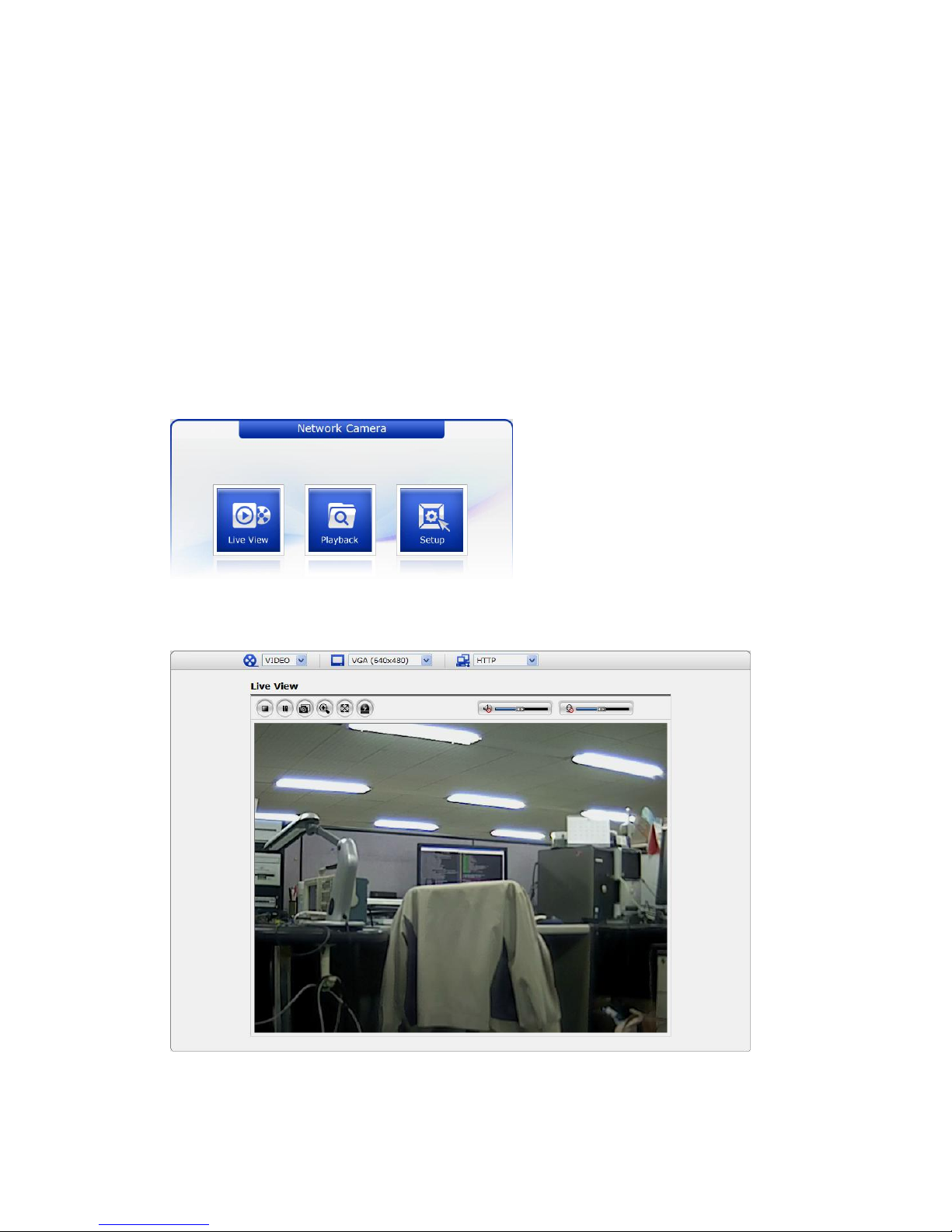
3. You can see a starting page. Click Live View or Setup to enter web page.
4. The encoder’s Live View page appears in your browser.
17
3.2. Access from the internet
Access from the internet once connected, the Network Camera is accessible on your local network
(LAN). To access the video encoder from the Internet you must configure your broadband router to
allow incoming data traffic to the video encoder. To do this, enable the NAT-traversal feature, which
will attempt to automatically configure the router to allow access to the video encoder. This is enabled
from Setup > System > Network > NAT.
For more information, please see “3.5.6 System>Network>NAT” of User’s Manual.
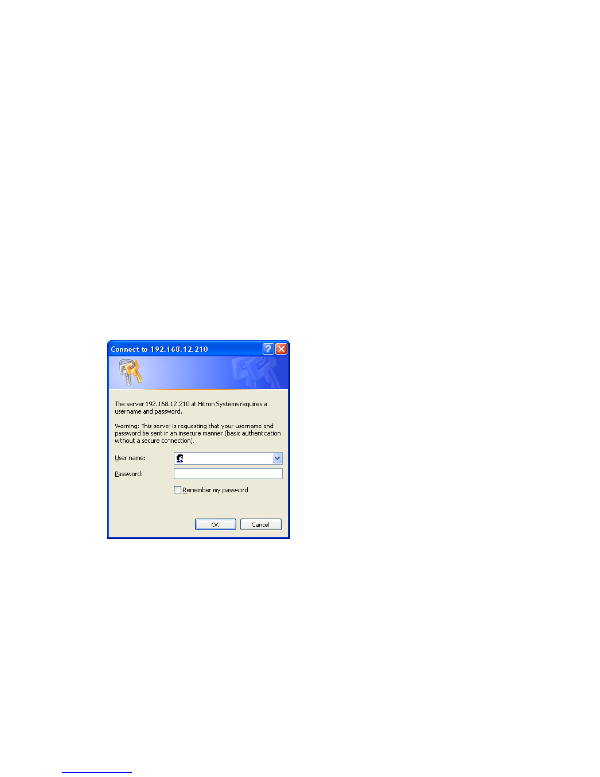
3.3 Setting the admin password over a secure connection
To gain access to the product, the password for the default administrator user must be set. This is
done in the “Admin Password” dialog, which is displayed when the network camera is accessed for the
setup at the first time. Enter your admin name and password, set by the administrator.
NOTE: The default administrator username and password is “admin”. If the password is lost, the
Network Camera must be reset to the factory default settings. See “3.8 Resetting to the Factory
Default Settings” for more details.
To prevent network eavesdropping when setting the admin password, this can be done via an
encrypted HTTPS connection, which requires an HTTPS certificate (see note below).
To set the password via a standard HTTP connection, enter it directly in the first dialog shown below.
To set the password via an encrypted HTTPS connection, see “3.5.6 System >Security>HTTPS”.
Note: HTTPS (Hypertext Transfer Protocol over SSL) is a protocol used to encrypt the traffic between
web browsers and servers. The HTTPS certificate controls the encrypted exchange of information.
18
3.4 Live View Page
The live view page comes in eight screen modes like 1920x1080, 1280x1024, 1280x720,
720x480(576), 640x480, 352x240(288), and 320x240. Users are allowed to select the most suitable
one out of those modes. Please, adjust the mode in accordance with your PC specifications and
monitoring purposes.
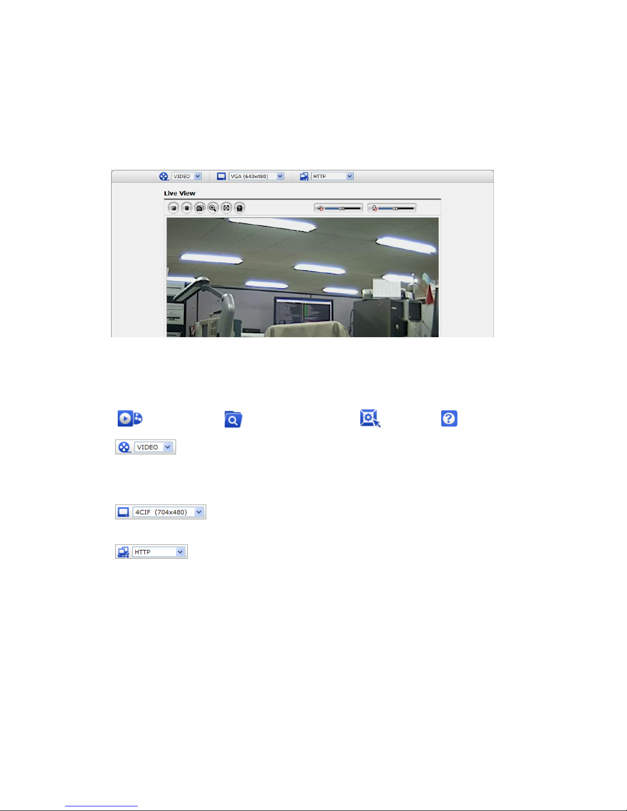
1) General controls
Live View Page Search & Playback Page Setup Page Help Page
The video drop-down list allows you to select a customized or pre-programmed
video stream on the live view page. Stream profiles are configured under Setup > Basic
Configuration > Video & Image. For more information, please see “3.5.1 Basic Configuration >
Video & Image” of User’s Manual.
The resolution drop-down list allows you to select the most suitable one
out of video resolutions to be displayed on live view page.
The protocol drop-down list allows you to select which combination of
protocols and methods to use depends on your viewing requirements, and on the properties of
your network.

19
2) Control toolbar
The live viewer toolbar is available in the web browser page only. It displays the following
buttons:
The Stop button stops the video stream being played. Pressing the key again toggles the
start and stop. The Start button connects to the network camera or start playing a
video stream.
The Pause button pause the video stream being played.
The Snapshot button takes a snapshot of the current image. The location where the
image is saved can be specified.
The digital zoom activates a zoom-in or zoom-out function for video image on the live
screen.
The Full Screen button causes the video image to fill the entire screen area. No other
windows will be visible. Press the 'Esc' button on the computer keyboard to cancel full
screen view.
The Manual Trigger button activates a pop-up window to manually start or stop the event.
The Camera Menu button activates a pop-up window for camera menu control.
Use this scale to control the volume of the speakers.
Use this scale to control the volume of the microphone.
Use this scale to control the volume of the speakers and microphones.
3) Video and Audio Streams
The video encoder provides several images and video stream formats. Your requirements and the
properties of your network will determine the type you use.
The Live View page in the video encoder provides access to H.264, MPEG-4 and Motion JPEG
video streams, and to the list of available video streams. Other applications and clients can also
access these video streams/images directly, without going via the Live View page.
20
3.5 Network Camera Setup
This section describes how to configure the network camera, and is intended for product
Administrators, who have unrestricted access to all the Setup tools; and Operators, who have access
to the settings for Basic, Live View, Video & Image, Audio, Event, and System Configuration.
You can configure the network camera by clicking Setup in the top right-hand corner of the Live View
page. Click on this page to access the online help that explains the setup tools
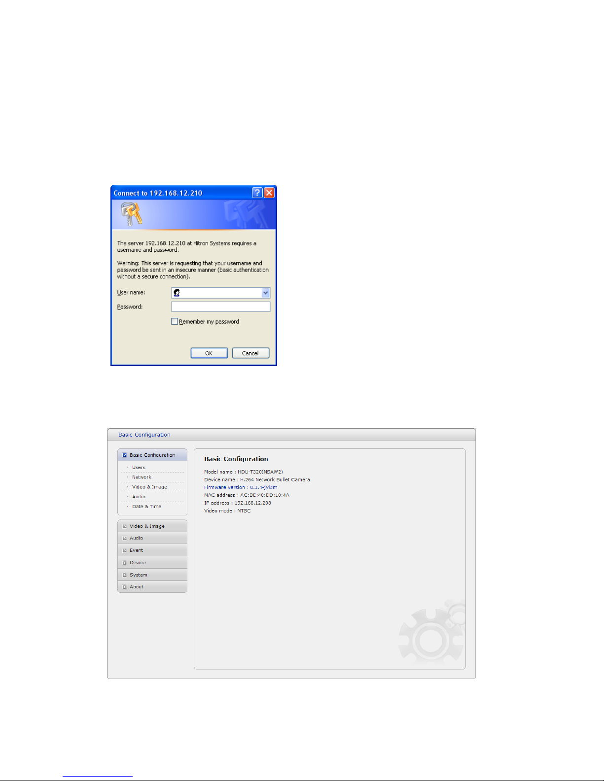
When accessing the Network Camera for the first
time, the “Admin Password” dialog appears.
Enter your admin name and password, set by the
administrator.
Note: If the password is lost, the Network
Camera must be reset to the factory default
settings. See “3.8 Resetting to the Factory
Default Settings”.
3.5.1 Basic Configuration
You can see the device information in this information page.

21
1) Users
User access control is enabled by default. An administrator can set up other users, by giving these
user names and passwords. It is also possible to allow anonymous viewer login, which means that
anybody may access the Live View page, as described below:
The user list displays the authorized users and user groups (levels):
User Group
Authority
Guest
Provides the lowest level of access, which only allows access to the
Live View page.
Operator
An operator can view the Live View page, create and modify
events, and adjust certain other settings. Operators have no access
to System Options.
Administrator
An administrator has unrestricted access to the Setup tools and can
determine the registration of all other users.
Enable anonymous viewer login: Check the box to use the webcasting features. Refer to
“3.5.2 Video & Image” for more details.
22
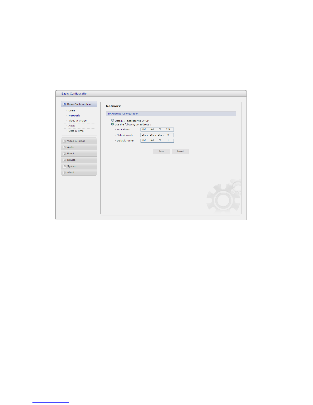
2) Network
The network camera support both IP version 4 and IP version 6. Both versions may be enabled
simultaneously, and at least one version must always be enabled. When using IPv4, the IP address for
the video encoder can be set automatically via DHCP, or a static IP address can be set manually.
If IPv6 is enabled, the video encoders receive an IP address according to the configuration in the
network router. There is also the option of using the Internet Dynamic DNS Service. For more
information on setting the Network, please see Setup> System>Security>Network.
• Obtain IP address via DHCP - Dynamic Host Configuration Protocol (DHCP) is a protocol
that lets network administrators centrally manage and automate the assignment of IP
addresses on a network. DHCP is enabled by default. Although a DHCP server is mostly
used to set an IP address dynamically, it is also possible to use it to set a static, known IP
address for a particular MAC address.
• Use the following IP address - To use a static IP address for the Network Camera,
check the radio button and then make the following settings:
- IP address - Specify a unique IP address for your Network Camera.
- Subnet mask - Specify the mask for the subnet the Network Camera is located on.
- Default router - Specify the IP address of the default router (gateway) used for
connecting devices attached to different networks and network segments.
Notes:
1. DHCP should only be enabled if using dynamic IP address notification, or if your DHCP server can
update a DNS server, which then allows you to access the Network Camera by name (host name).
If DHCP is enabled and you cannot access the unit, you may have to reset it to the factory
default settings and then perform the installation again.
2. The ARP/Ping service is automatically disabled two minutes after the unit is started, or
as soon as an IP address is set.
3. Pinging the unit is still possible when this service is disabled.
23
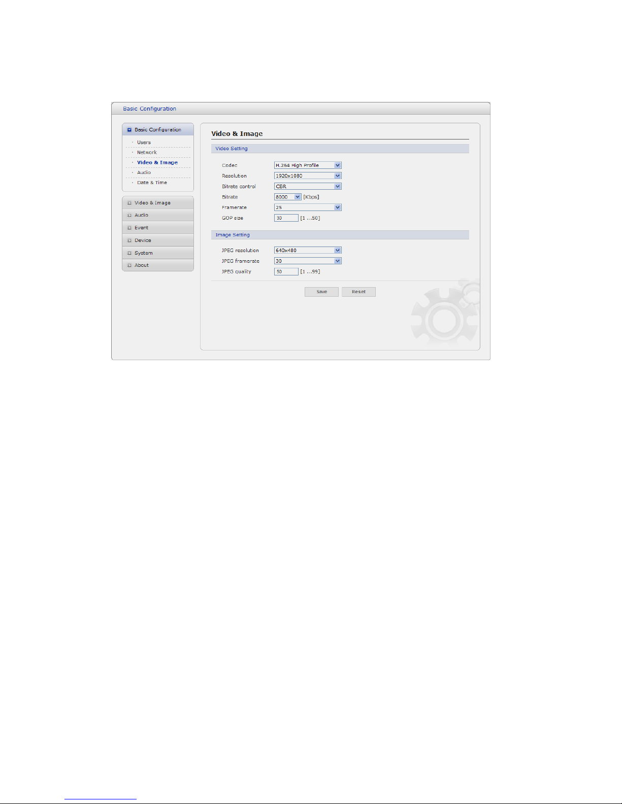
3) Video & Image
• Video Setting
- Codec:
The codec settings are separated into MPEG4 and H.264.
H.264 is also known as MPEG-4 Part 10. This is the new generation compression standard for digital
video. This function offers higher video resolution than Motion JPEG or MPEG-4 at the same bit rate and
bandwidth, or the same quality video at a lower bit rate.
- Profile:
There are 4 pre-programmed stream profiles available for quick set-up.
Choose the form of video encoding you wish to use from the drop-down list:
* H.264 MP(Main Profile):
Primarily for low-cost applications that requires additional error robustness, this profile is
used rarely in videoconferencing and mobile applications, it does add additional error
resilience tools to the Constrained Baseline Profile. The importance of this profile is fading
after the Constrained Baseline Profile has been defined.
* H.264 BP(Base Profile):
Originally intended as the mainstream consumer profile for broadcast and storage
applications, the importance of this profile faded when the High profile was developed for
those applications.
* MPEG4 SP(Simple Profile):
Mostly aimed for use in situations where low bit rate and low resolution are mandated by
other conditions of the applications, like network bandwidth, device size etc.

24
* MPEG4 ASP(Advanced Simple Profile):
Its notable technical features relative to the Simple Profile, which is roughly similar to H.263,
including "MPEG"-style quantization, interlaced video, B pictures (also known as B Frames),
Quarter Pixel motion compensation (Qpel), Global motion compensation (GMC).
- Resolution:
It enables users to determine a basic screen size when having an access through the Web
Browser or PC program. The screen size control comes in seven modes like 1920x1080,
1280x1024, 1280x720, 704x480(576), 640x480, 352x240(288), and 320x240. Users can
reset the selected screen size anytime while monitoring the screen on a real-time basis.
- Bitrate control:
Limiting the maximum bit rate helps control the bandwidth used by the H.264 or MPEG-4
video stream. Leaving the Maximum bit rate as unlimited maintains consistently good image
quality but increases bandwidth usage when there is more activity in the image. Limiting the
bit rate to a defined value prevents excessive bandwidth usage, but images are lost when
the limit is exceeded.
Note that the maximum bit rate can be used for both variable and constant bit rates.
The bit rate can be set as Variable Bit Rate (VBR) or Constant Bit Rate (CBR). VBR adjusts
the bit rate according to the image complexity, using up bandwidth for increased activity in
the image, and less for lower activity in the monitored area.
CBR allows you to set a fixed target bitrate that consumes a predictable amount of
bandwidth. As the bit rate would usually need to increase for increased image activity, but in
this case cannot, the frame rate and image quality are affected negatively. To partly
compensate for this, it is possible to prioritize either the frame rate or the image quality
whenever the bit rate needs to be increased. Not setting a priority means the frame rate and
image quality are equally affected.
- Compression:
When it is necessary to adjust a smooth transmission status according to network situations,
users can increase the compressibility to carry out the network transmission stably. On the
other hand, when it is necessary to maintain a detailed monitoring screen by enhancing the
image quality, users can do so by decreasing the compressibility. In ease case, please adjust
this function according to the network status and monitoring purposes. The default is
2000(Kbps).
- Frame rate:
Upon the real-time play, users should select a frame refresh rate per second. If the rate is
high, the image will become smooth. On the other hand, if the rate is low, the image will not
be natural but it can reduce a network load.
- GOP size:
Select the GOP(Group of Picture) size. If users want to have a high quality of fast image one
by one, please decrease the value. For the purpose of general monitoring, please do not
change a basic value. Such act may cause a problem to the system performance. For the
details of GOP setting, please contact the service center.
 Loading...