

Xineron FASTRAX III Instruction Manual
WARNING
TO REDUCE THE RISK OF FIRE OR ELECTRIC SHOCK, DO NOT EXPOSE THIS PRODUCT TO RAIN
OR MOISTURE. DO NOT INSERT ANY METALLIC OBJECTS THROUGH THE VENTILATION GRILLS
OR OTHER OPENINGS ON THE EQUIPMEMT.
CAUTION
EXPLANATION OF GRAPHICAL SYMBOLS
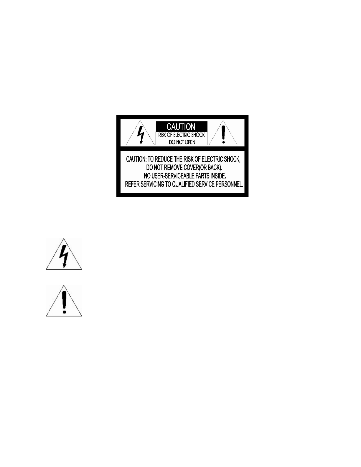
The lightning flash with arrowhead symbol, within an equilateral
triangle, is intended to alert the user to the presence of uninsulated
“dangerous voltage” within the product’s enclosure that may be of
sufficient magnitude to constitute a risk of electric shock to persons.
The exclamation point within an equilateral is intended to alert the user
to the presence of important operating and maintenance (servicing)
instructions in the literature accompanying the appliance.

FCC COMPLIANCE STATEMENT
CE COMPLIANCE STATEMENT
FCC INFORMATION: THIS EQUIPMENT HAS BEEN TESTED AND FOUND TO
COMPLY WITH THE LIMITS FOR A CLASS A DIGITAL DEVICE, PURSUANT TO
PART 15 OF THE FCC RULES. THESE LIMITS ARE DESIGNED TO PROVIDE
REASONABLE PROTECTION AGAINST HARMFUL INTERFERENCE WHEN
THE EQUIPMENT IS OPERATED IN A COMMERCIAL ENVIRONMENT. THIS
EQUIPMENT GENERATES, USES, AND CAN RADIATE RADIO FREQUENCY
ENERGY AND IF NOT INSTALLED AND USED IN ACCORDANCE WITH THE
INSTRUCTION MANUAL, MAY CAUSE HARMFUL INTERFERENCE TO RADIO
COMMUNICATIONS. OPERATION OF THIS EQUIPMENT IN A RESIDENTIAL
AREA IS LIKELY TO CAUSE HARMFUL INTERFERENCE IN WHICH CASE THE
USER WILL BE REQUIRED TO CORRECT THE INTERFERENCE AT HIS OWN
EXPENSE.
CAUTION: CHANGES OR MODIFICATIONS NOT EXPRESSLY APPROVED BY
THE PARTY RESPONSIBLE FOR COMPLIANCE COULD VOID THE USER'S
AUTHORITY TO OPERATE THE EQUIPMENT.
THIS CLASS A DIGITAL APPARATUS COMPLIES WITH CANADIAN ICES-003.
CET APPAREIL NUMÉRIQUE DE LA CLASSE A EST CONFORME À LA NORME
NMB-003 DU CANADA.
WARNING
THIS IS A CLASS A PRODUCT. IN A DOMESTIC ENVIRONMENT THIS
PRODUCT MAY CAUSE RADIO INTERFERENCE IN WHICH CASE THE USER
MAY BE REQUIRED TO TAKE ADEQUATE MEASURES.

IMPORTANT SAFETY INSTRUCTIONS
1. Read these instructions.
2. Keep these instructions.
3. Heed all warnings.
4. Follow all instructions.
5. Do not use this apparatus near water.
6. Clean only with dry cloth.
7. Do not block any ventilation openings. Install in accordance with the manufacturer’s
instructions.
8. Do not install near any heat sources such as radiators, heat registers, stoves, or
other apparatus (including amplifiers) that produce heat.
9. Do not defeat the safety purpose of the polarized or grounding-type plug. A
polarized plug has two blades with one wider than the other. A grounding type plug
has two blades and a third grounding prong. The wide blade or the third prong are
provided for your safety. If the provided plug does not fit into your outlet, consult an
electrician for replacement of the obsolete outlet.
10. Protect the power cord from being walked on or pinched particularly at plugs,
convenience receptacles, and the point where they exit from the apparatus.
11. Only use attachments/accessories specified by the manufacturer.
12. Use only with the cart, stand, tripod, bracket, or table specified by
the manufacturer, or sold with the apparatus. When a cart is used,
use caution when moving the cart/apparatus combination to avoid
injury from tip-over.
13. Unplug this apparatus during lightning storms or when unused for
long periods of time.
14. Refer all servicing to qualified service personnel. Servicing is required when the
apparatus has been damaged in any way, such as power-supply cord or plug is
damaged, liquid has been moisture, does not operate normally, or has been
dropped.
15. CAUTION – THESE SERVICING INSTRUCTIONS ARE FOR USE BY
QUALIFIED SERVICE PERSONNEL ONLY. TO REDUCE THE RISK OF
ELECTRIC SHOCK DO NOT PERFORM ANY SERVICING OTHER THAN
THAT CONTAINED IN THE OPERATING INSTRUCTIONS UNLESS YOU
QRE QUALIFIED TO DO SO.
16. Use satisfy clause 2.5 of IEC60950-1/UL60950-1 or Certified/Listed Class 2
power source only.
17. ITE is to be connected only to PoE networks without routing to the outside plant.

Table of Contents
Chapter 1 — Introduction ......................................................................................................... 1
1.1 Features .............................................................................................................................................. 1
Chapter 2 — Installation and Configuration ........................................................................... 3
2.1 Package Contents ............................................................................................................................... 3
2.2 Basic Configuration of Fastrax III Network Dome Camera System .................................................... 4
2.3 Setting Dome Camera Termination ..................................................................................................... 5
2.4 Setting Network Dome Camera Address (ID) ..................................................................................... 6
2.5 Connections ........................................................................................................................................ 7
2.6 IP Assignment ..................................................................................................................................... 8
2.7 Getting Started .................................................................................................................................... 9
Chapter 3 — Program and Operation .................................................................................... 10
3.1 Dome Camera Selection ................................................................................................................... 10
3.2 Accessing On-Screen Menu Utility .................................................................................................... 10
3.3 How to control On-Screen Menu Utility ............................................................................................. 10
3.4 Auto Scan ........................................................................................................................................... 11
3.5 Preset ................................................................................................................................................ 13
3.6 Shortcut of Preset Program............................................................................................................... 14
3.7 Tour .................................................................................................................................................. 15
3.8 Pattern ............................................................................................................................................... 16
3.9 Area Title .......................................................................................................................................... 17
3.10 Privacy Zone ................................................................................................................................... 18
3.11 Camera Menu type 1 ....................................................................................................................... 19
3.12 Camera Menu type 2 ....................................................................................................................... 22
3.13 Dome Setup .................................................................................................................................... 25
3.14 Dome Communication ..................................................................................................................... 32
3.15 Function Run ................................................................................................................................... 32
3.16 Factory Setup .................................................................................................................................. 33
Chapter 4 — Operation by Web Browser .............................................................................. 34
4.1 Access from a browser ...................................................................................................................... 34
4.2 Access from the internet .................................................................................................................... 35
4.3 Setting the admin password over a secure connection .................................................................... 35
4.4 Live View Page.................................................................................................................................. 36
4.5 Network Camera Setup ..................................................................................................................... 37
4.5.1 Basic Configuration ........................................................................................................................ 38
4.5.2 Video & Image ............................................................................................................................... 44
4.5.3 Audio .............................................................................................................................................. 45
4.5.4 Event .............................................................................................................................................. 45

4.5.5 System ........................................................................................................................................... 56
4.5.6 About .............................................................................................................................................. 68
4.6 PTZ Control ....................................................................................................................................... 69
4.7 Help ................................................................................................................................................... 70
4.8 Resetting to the factory default settings ............................................................................................ 70
4.9 System Requirement for Web Browser ............................................................................................. 71
Appendix A — Specifications ................................................................................................ 72
Appendix B — Troubleshooting ............................................................................................ 74
Appendix C — Glossary ......................................................................................................... 75
Appendix D — Short Cut Key ................................................................................................ 77

Chapter 1 — Introduction
1.1 Features
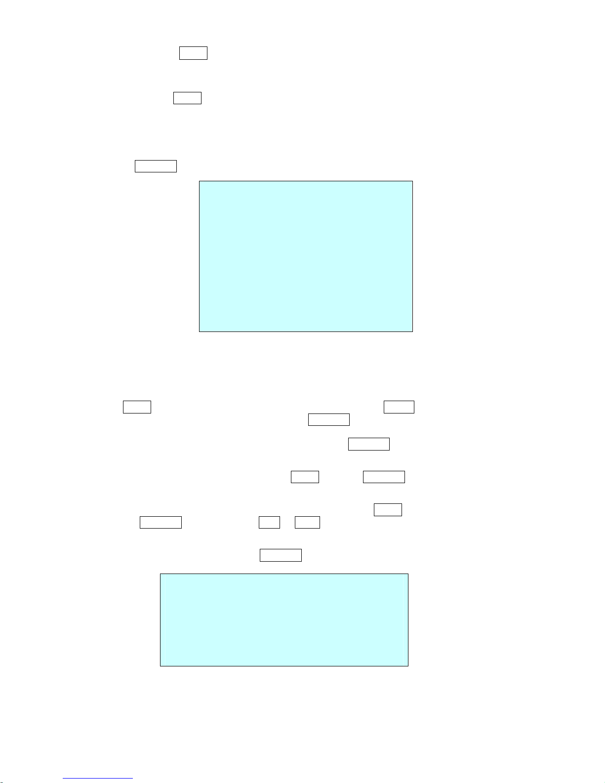
The dome camera and the keyboard controller, PC software makes up the building blocks for any
surveillance/security system. Using multiple keyboard controllers and multiple dome cameras, no place is
too large for monitoring. Extensible and flexible architecture facilitates remote control functions for a
variety of external switching devices such as multiplexers and DVRs.
• Built-in optical power zoom camera with True Night Shot function.
• Dual video streams simultaneously at full frame rate in all resolutions up to D1 (720X480 in NTSC,
720X576 in PAL) using Motion JPEG and H.264 (or MPEG-4).
• Intelligent capabilities such as enhanced video motion detection
The encoder’s external inputs and outputs can be connected to devices such as sensors and relays,
enabling the system to react to alarms and activate lights or open/close doors.
• Supports two-way audio
• Logs all user access, and lists currently connected users. Also, full frame rate video can be provided
over HTTPS.
• Interface Protocol: TCP/IP, UDP, IPv4/v6, HTTP, HTTPS, QoS, FTP, SNMP, uPnP, RTP, RTSP, RTCP,
DHCP, ARP
• 240 Preset positions with the individual Camera AE setup
• 8 Tours consist of Preset, Pattern, Auto-Scan and other Tours can be programmed with over 300
functions and Preset location. While moving, each Preset scan can be watched in smooth Vector Scan
mode.
• 16 Auto Scans with the normal, the vector, and the random mode and the Endless Auto-Pan with 13
speed steps.
• 8 Patterns (up to 500second) and 8 Privacy zones.
• 16 Area Titles.
• 1 Alarm input / 1 Alarm output
• Variable speed from 0.1°/sec to 380°/sec.
Three Variable speed (SLOW, NORMAL, TURBO)
Turbo speed is Max 380°/sec with Ctrl key pressed.
• Pan / Tilt speed is inversely proportional to the zoom ratio with the option.
• Maximum speed is 380°/sec when preset command.
• Auto Calibration from 0.1° to 6° (Tilt range is 0° to 180°).
• Programmable user preferences (alarm, preset, title, etc.).
• 180° Digital Flip or 90° Auto Flip depended on the model.
• Up to 999 selectable camera addresses (3999 by software setting).
• Multi-language Menu Display, Password Confirmation.
• Function Run menu using DVR without function key (Pattern, SCAN,..)
• Built-in RS-485 receiver driver.
• Optional Clear bubble with black liner (shelter) for concealing the camera.
• Optional Tinted Bubble, Indoor & Outdoor pendant housing with heater & blower, Indoor Flush mount,
Parapet mount & Roof Top mount.
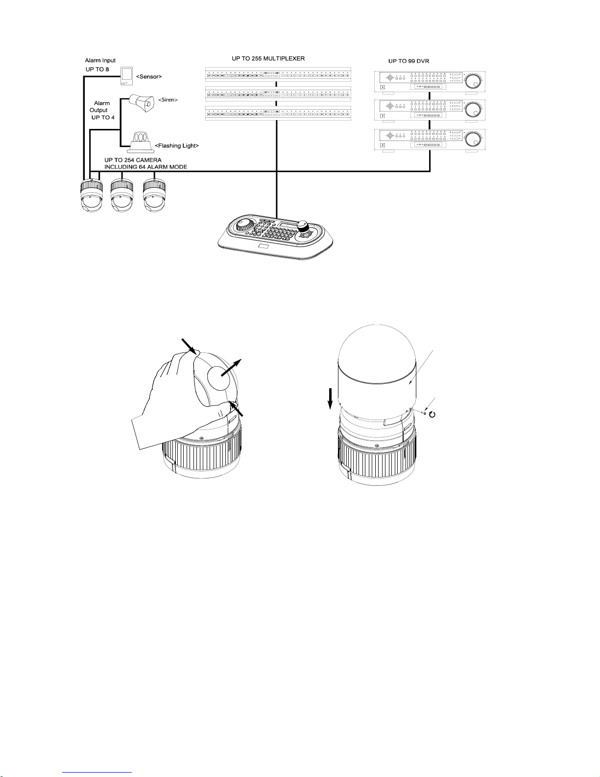
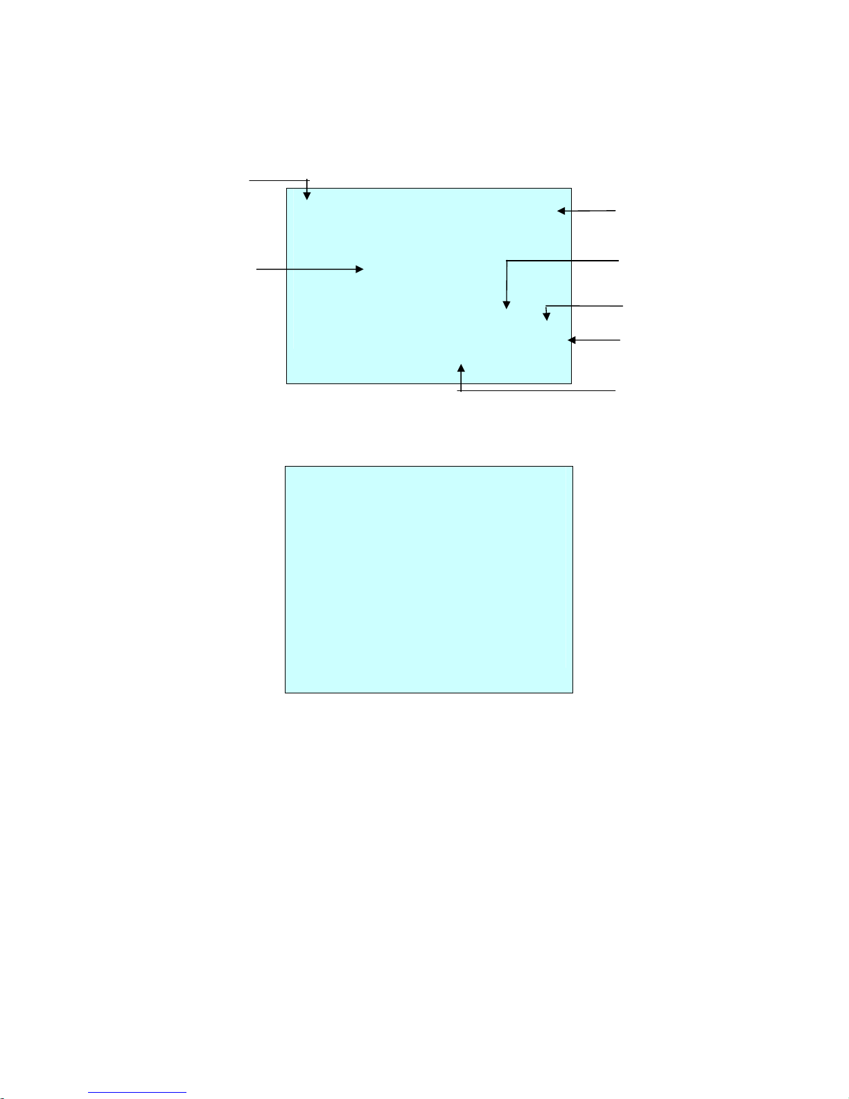
Figure 1 – Typical System Configuration
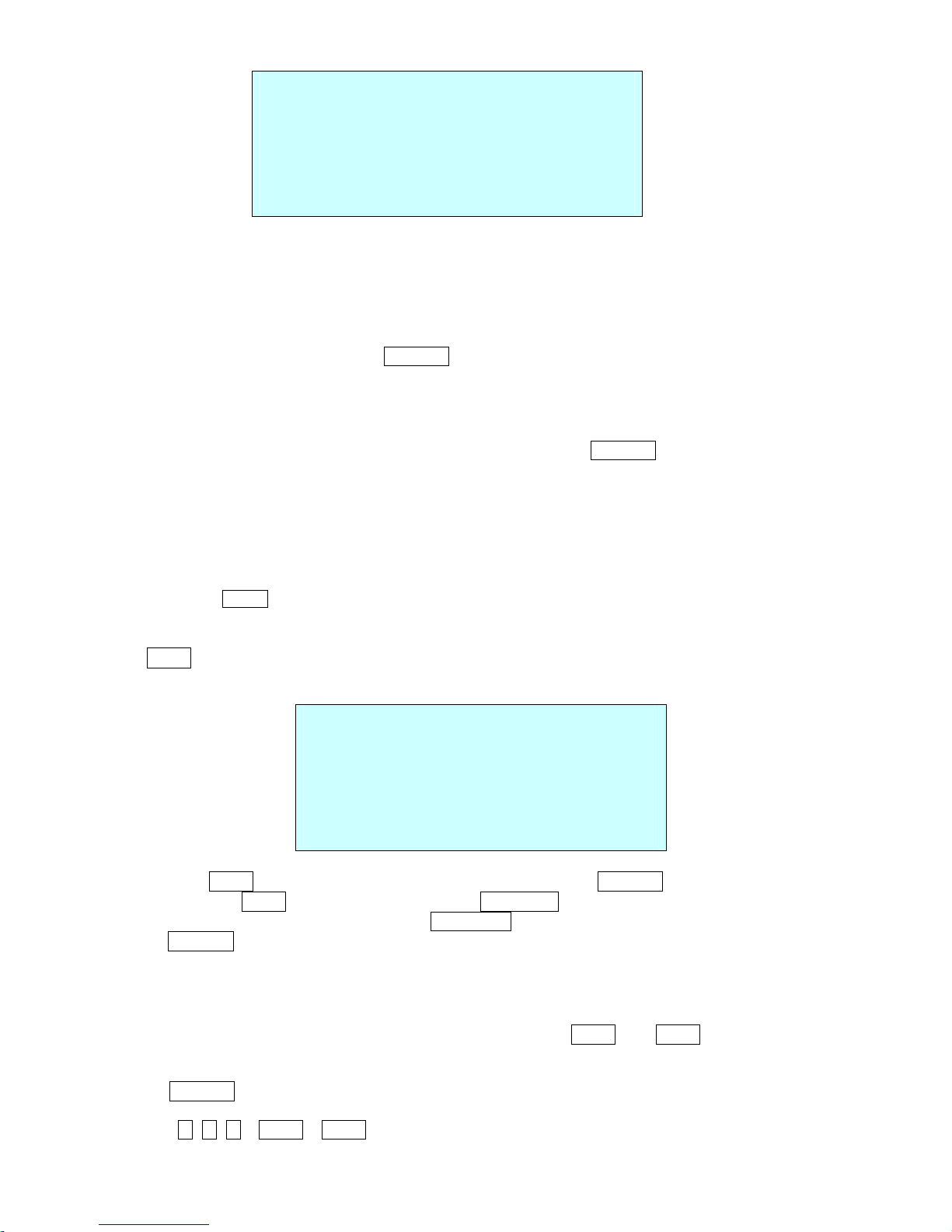
push
push
remove camera window
remove window
assemble bubble ring ass'y
bubble ring ass'y
screw
Figure 2 –Assemble bubble ring ass’y (Optional)
Note:
It is recommended to remove camera window for improving picture quality when you use bubble
ring ass’y.
CAUTION
: When installing a Fastrax dome on a high pole outside, caution should be taken to avoid
vibration and shaking of Fastrax dome due to windload or shock of passing heavy vehicles. If
pole is not stable enough, it may cause malfunction in accurate tilt positioning.
Chapter 2 — Installation and Configuration
2.1 Package Contents
The package contains the following.
Fastrax III Network Dome Camera ………………………1
Bubble Ring ………………………1(Optional)
Instruction Guide /CD ………………………1
Assembly Screws for Attaching Fastrax III ………………………3
Plastic Anchor ………………………3
Assembly Cable ………………………1
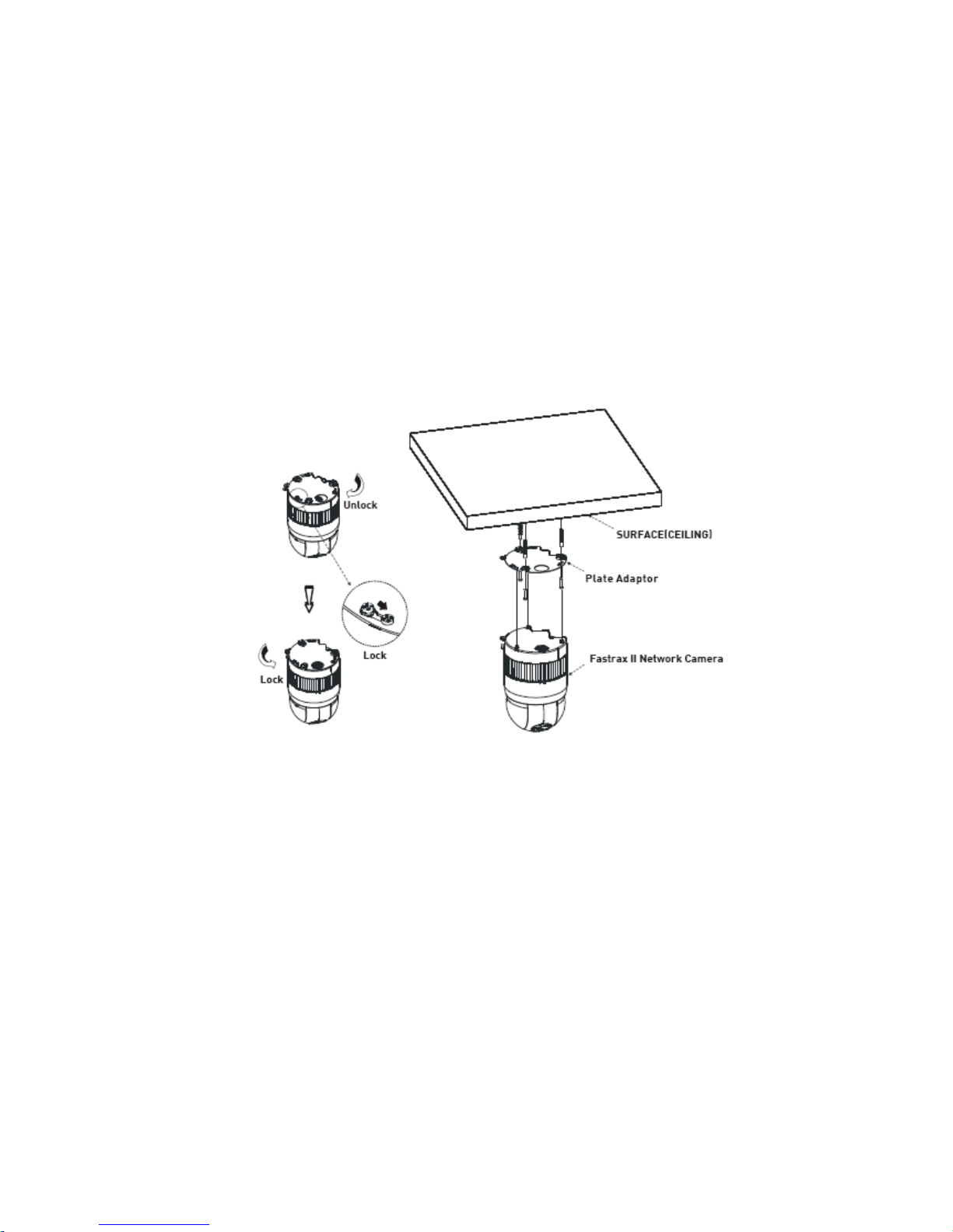
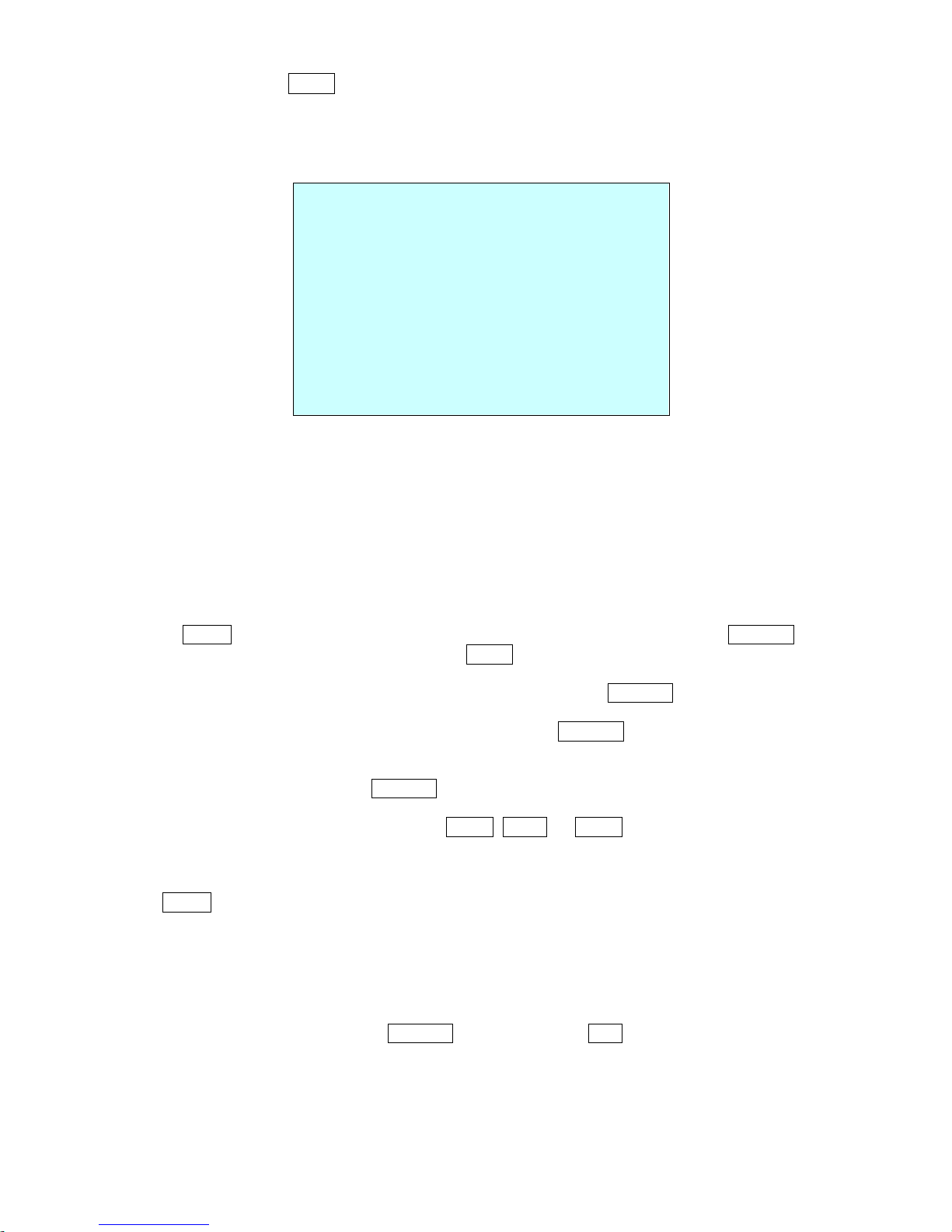
The Network Dome Camera is for use in surface mounting applications and the mounting surface should
be capable of supporting loads up to 10lb (4.5kg).
The Network Dome Camera’s base should be attached to a structural object, such as hard wood, wall stud
or ceiling rafter that supports the weight of the Network Dome Camera.
Figure 3 – Installation
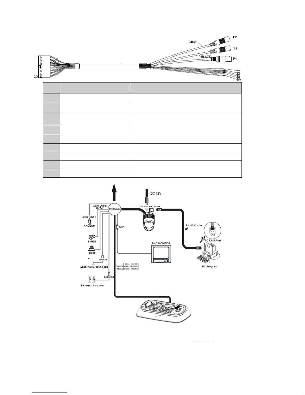
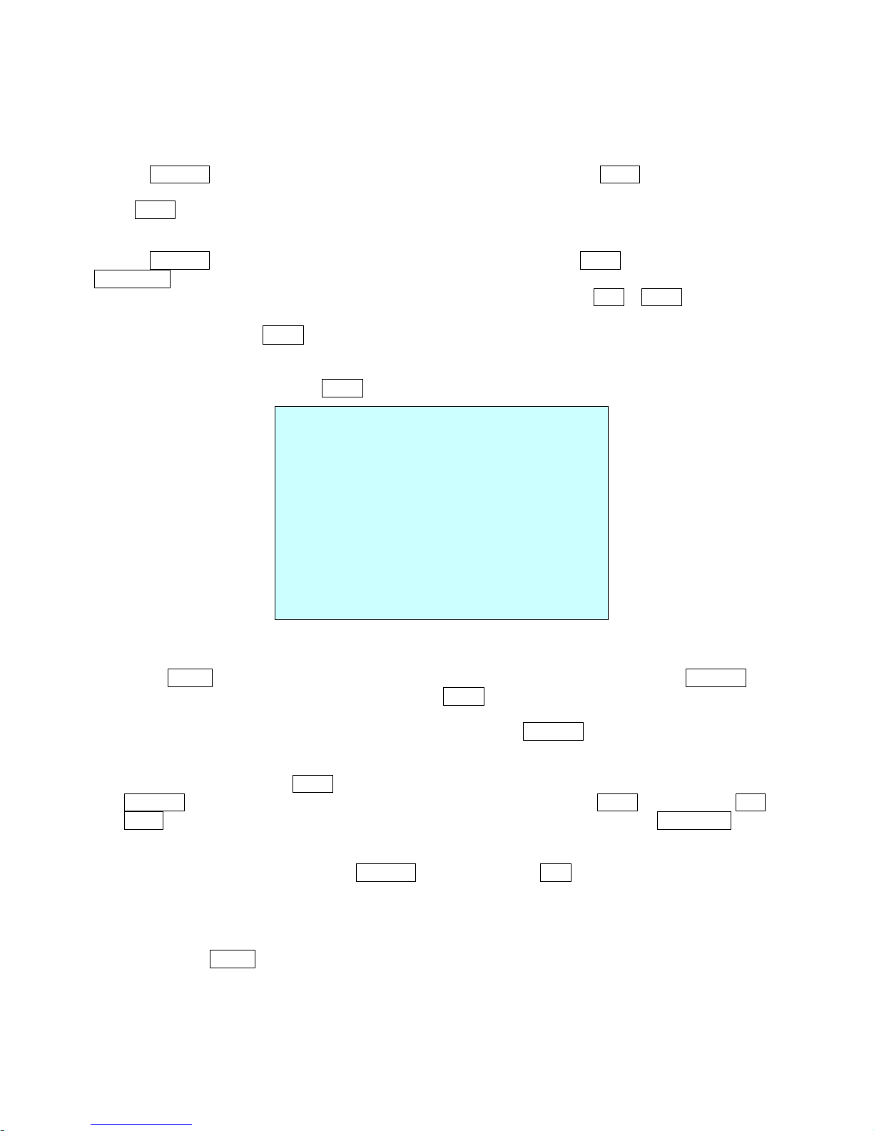
2.2 Basic Configuration of Fastrax III Network Dome Camera system
No.
Wire Color Description
P2
Gray Cable (Connector)
Audio Output
P3
Black Cable (Connector) Audio Input
P4
Yellow Cable
(BNC Connector)
Video Output
P5
Black RS 485 RX+
P6
Brown RS 485 RX-
P7
Blue Alarm Input 1
P8
Violet Ground
P9
Green
Alarm Output
P10
Yellow
Figure 4 – Basic installation diagram
The Network Dome Camera must be installed by qualified service personnel in accordance with all local
and federal electrical and building codes. The system should be installed according to Figures 4 through 7.
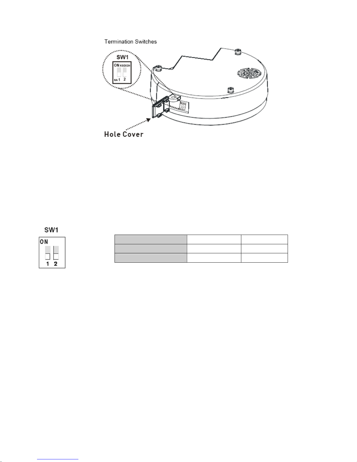
Figure 5 – Layout of Switches
2.3 Setting Dome Camera Termination
The device which is connected at end of line, whether it be a dome camera or keyboard controller, must
have the cable for communication terminated by setting the appropriate DIP switch. Without proper
termination, there is potential for control signal errors. Total length of the cable for communication should
not exceed 4000ft (1.2km).
Figure 6 – Setting Dome Camera Termination
SW1
1 2
Terminated
ON ON
Not terminated
OFF OFF
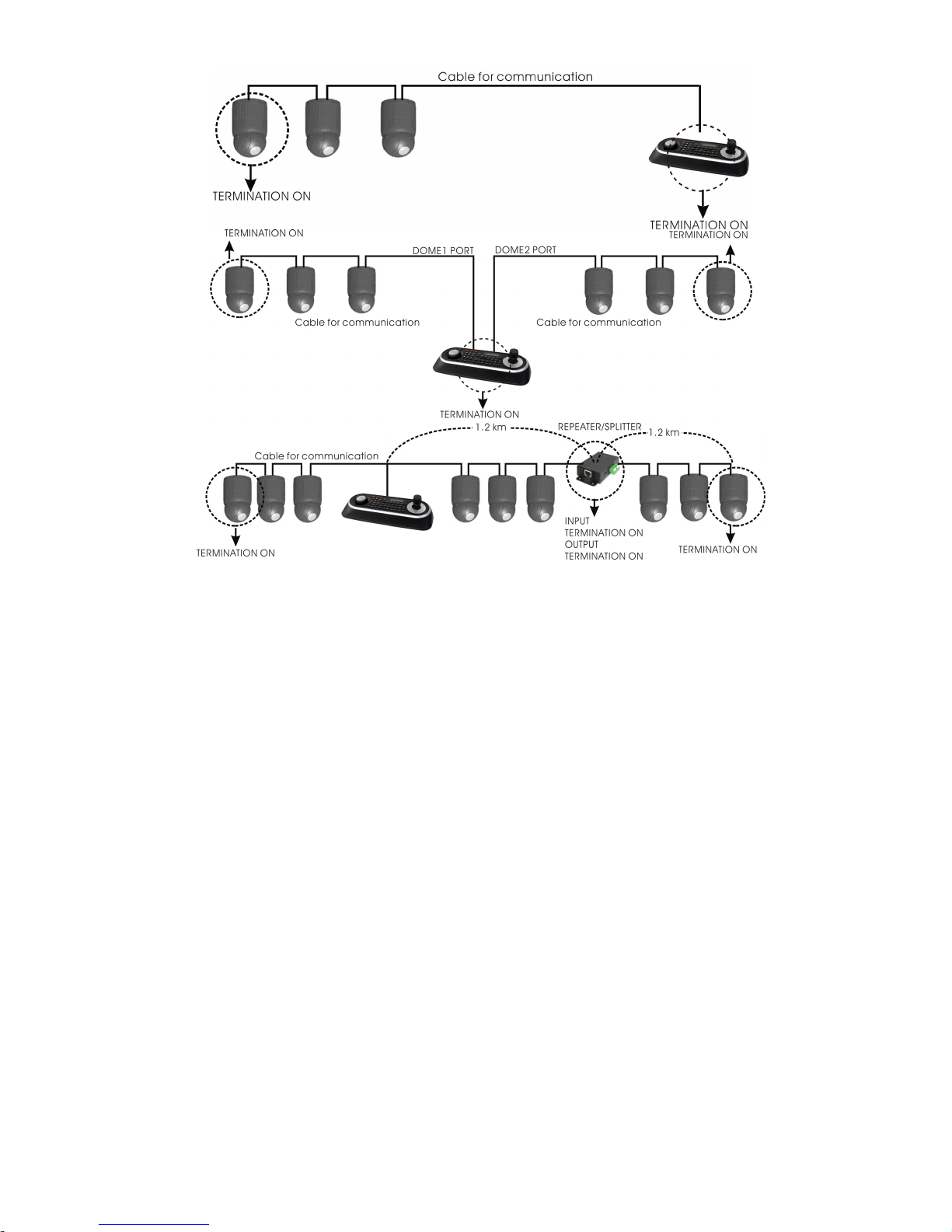
FIGURE 7 – TERMINATION DIAGRAM
2.4 Setting Network Dome Camera Address (ID)
To prevent damage, each dome camera must have a unique address (ID).
When installing multiple dome cameras using a multiplexer, it is suggested that the dome camera address
match the multiplexer port number.
The factory default setting is 1.
Refer to ‘3.14 Dome Communication’ section for detailed information.

2.5 Connections
• Connecting to the RS485
The Network Dome Camera can be controlled remotely by an external device or control system, such as a
control keyboard, using RS485 half-duplex serial communications signals. Connect Marked Rx+, Rx- to
Tx+ and Tx- of the RS485 control system.
If control system is RS422, connect Rx+(Tx+), Rx+(Tx-) and Rx+, Rx- of the dome camera to Rx+, Rxand Tx+, Tx- of the control device respectively.
• Connecting Video out connector
Connect the video out (BNC) connector to the monitor or video input.
• Connecting Alarms
AL1 (Alarm In)
You can use external devices to signal the dome camera to react on events. Mechanical or electrical
switches can be wired to the AL (Alarm In) and GND (Ground) connectors..
Please see “4.5.4 Event > 1) Event-In > ② Alarm In” for configuring alarm input .
GND (Ground)
NOTE: All the connectors marked GND are common.
Connect the ground side of the Alarm input and/or alarm output to the GND connector.
NC(NO) (Normal Close or Normal Open : Alarm Out)
The Network Dome Camera can activate external devices such as buzzers or lights. Connect the device
to the NC(NO) (Alarm Out) and COM (Common) connectors.
Please see “4.5.4 Event > 2) Event-Out > ④ Alarm Out” for configuring alarm output.
• Connecting the Network
The Network Dome Camera supports the operation through the network. Therefore, it is necessary to
connect a standard RJ-45 cable to it. Generally a cross cable is used for directly connection to PC, while a
direct cable is used for connection to a hub.
• Connecting the Power
Connect the power of DC 12V to the Network Dome Camera.
Use satisfy clause 2.5 of IEC60950-1/UL60950-1 or Certified/Listed Class 2 power source only.
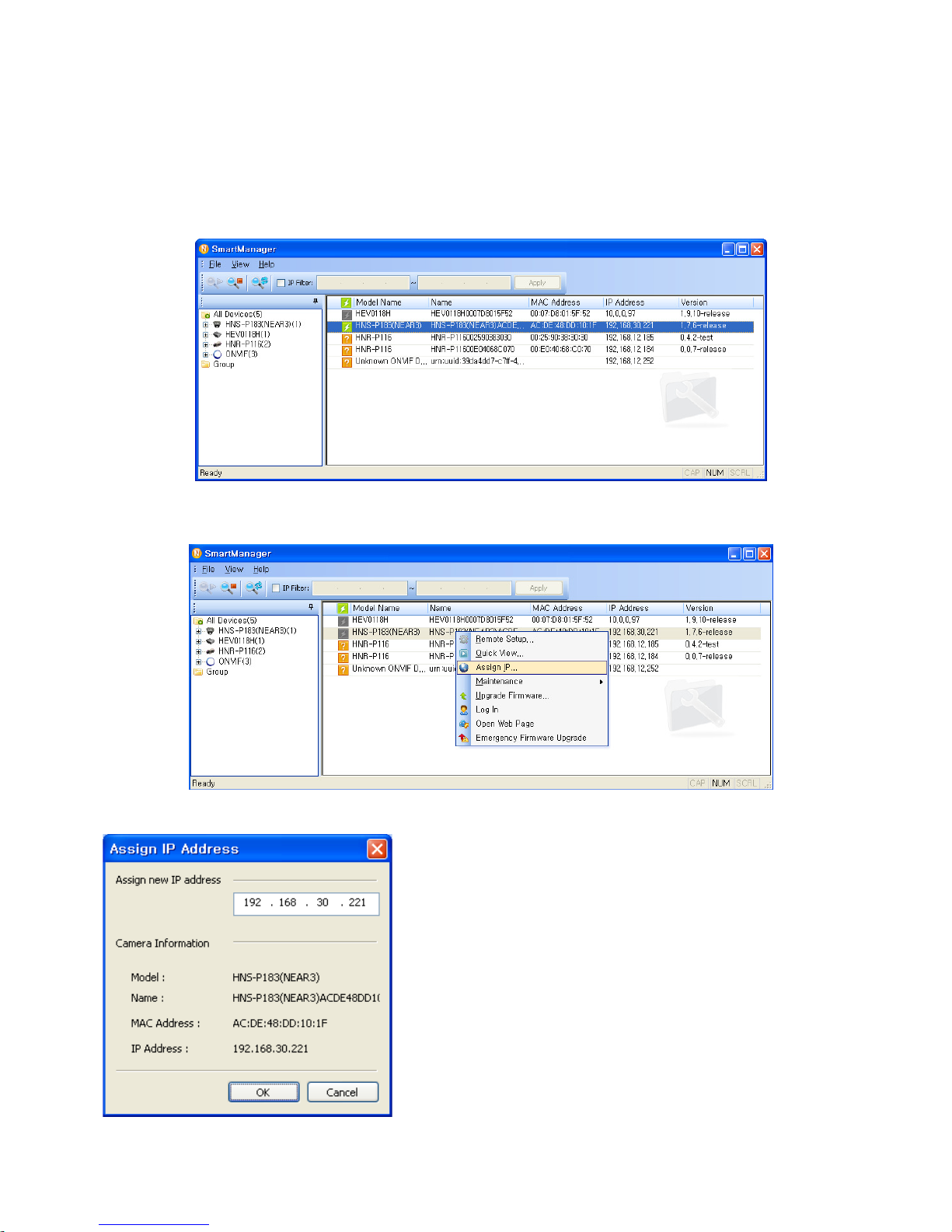
2.6 IP Assignment
When the dome camera, encoder or decoder is first connected to the network it has no IP address. So, it
is necessary to allocate an IP address to the device with the “SmartManager” utility on the CD.
1. Connect the dome camera / device to the network and power up.
2. Start SmartManager utility (All programs > NautilusClient16 > SmartManager), the main window will be
displayed, after a short while any network devices connected to the network will be displayed in the list.
3. Select the dome camera on the list and click right button of the mouse.
You can see the pop-up menu as below.
4. Select Assign IP Address. You can see Assign IP window. Enter the required IP address.
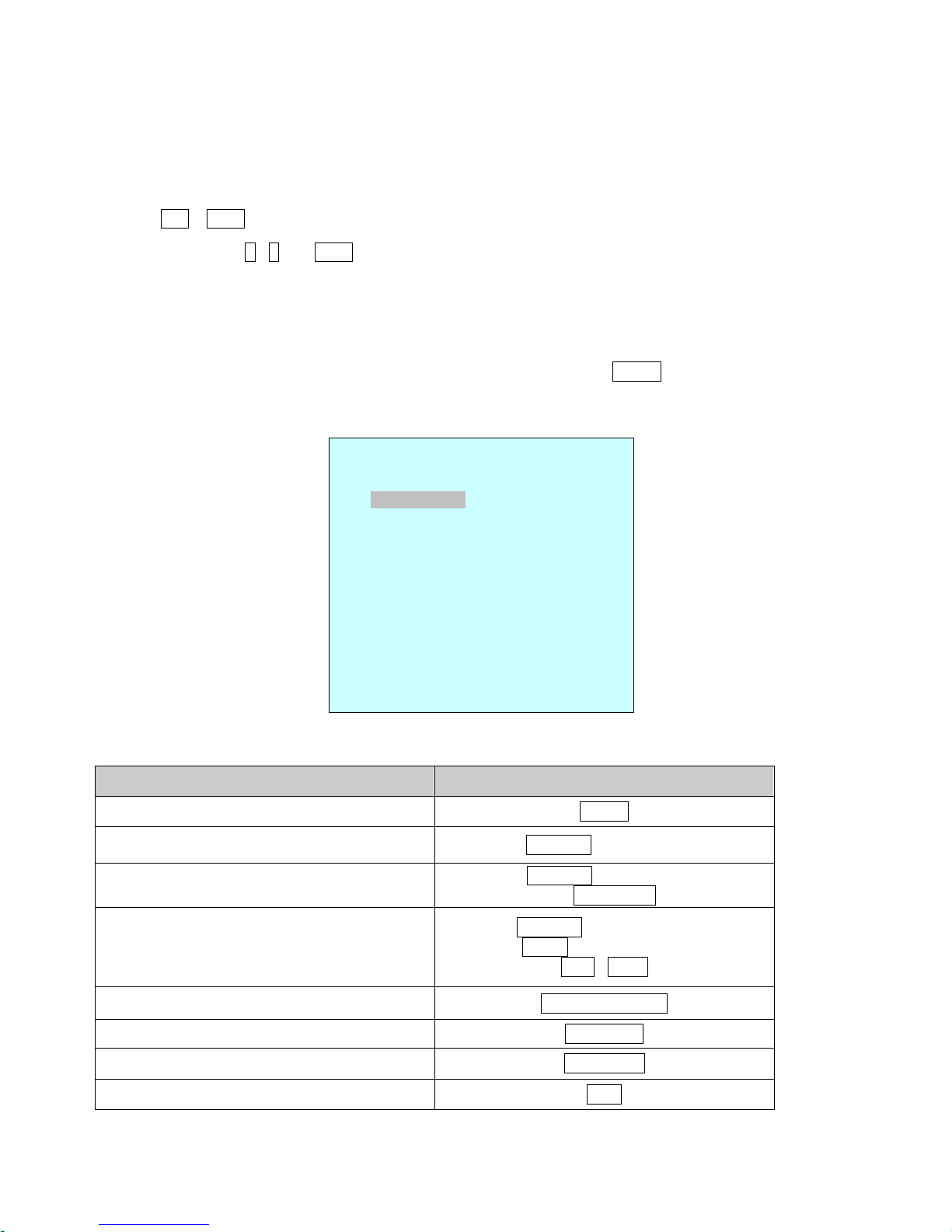
2.7 Getting Started
Once installed apply power to the dome camera. The dome camera will start a configuration sequence.
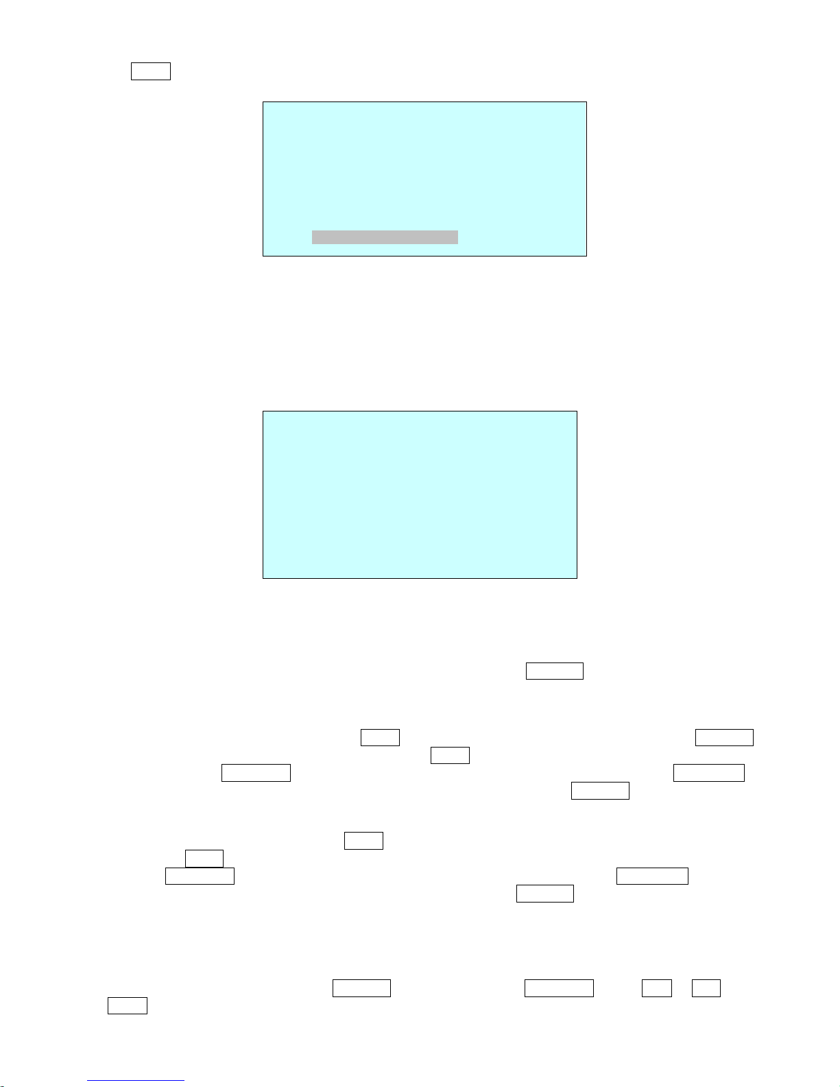
OSD Position
The dome can move the OSD position in the OSD position setup.
OSD Position Setup
001 AF AE
EMPTY DATA
DOMEID:0001
W→360.0,090.0
(AREA TITLE) (AF AE)
(FUNC TITLE )
(CTRL KEY TO MOVE)
SAVE AND EXIT(ESC TO CANCEL)
(DOME ID…)
(ANGLE…)
INFORMATION
DISPLAY
FUNCTION
UNDER RUNNING
CAMERA TITLE
CAMERA ID
VIEW DIRECTION
PAN & TILT ANGLE
PRESET TITLE
AREA TITLE
STATUS of
FOCUS and AE
Chapter 3 — Program and Operation
3.1 Dome Camera Selection
Before you program or operate a dome camera, you must select the dome camera by pressing the dome
camera
No.
+
CAM
Example:
Pressing 1 , 0 and
CAM
key sequentially will select dome camera 10. The selected dome
camera ID will be displayed on the LCD monitor of the keyboard controller.
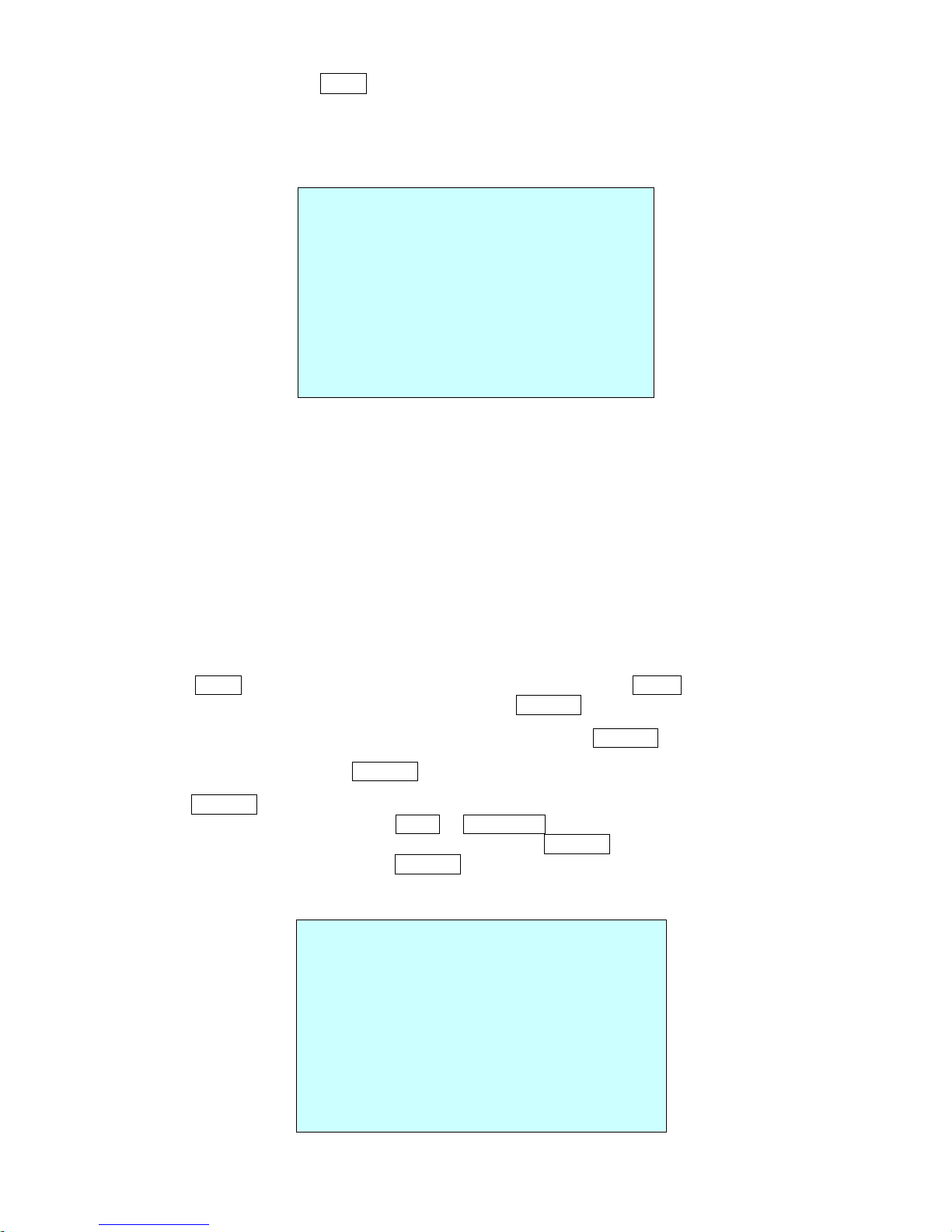
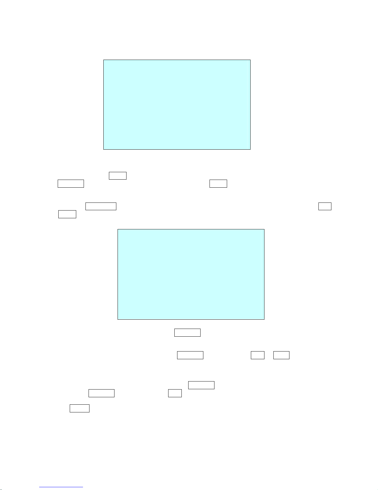
3.2 Accessing the On-Screen Menu Utility
You can call up the On-screen menu utility on your monitor by pressing
MENU
key on the keyboard
controller, the following On-screen menu utility will appear:
3.3 How to control the On-Screen Menu Utility
Function Button
Call the On-screen menu utility
MENU
Navigate through the menu items.
Joystick up or down
Go into the sub-menu items.
Joystick left or right
or IRIS Open
Change value.
Enter the editing title mode.
Joystick left or right or
Zoom handle twist or
Tele , Wide
Change value of angle
CTRL + Joystick
Enter the changing angle mode.
IRIS Open
Exit the changing angle mode.
IRIS Close
Escape (EXIT)
ESC
DOME MENU
AUTO SCAN
PRESET
TOUR
PATTERN
AREA TITLE
PRIVACY ZONE
CAMERA
DOME SETUP
FUNCTION RUN
EXIT(ESC TO EXIT)
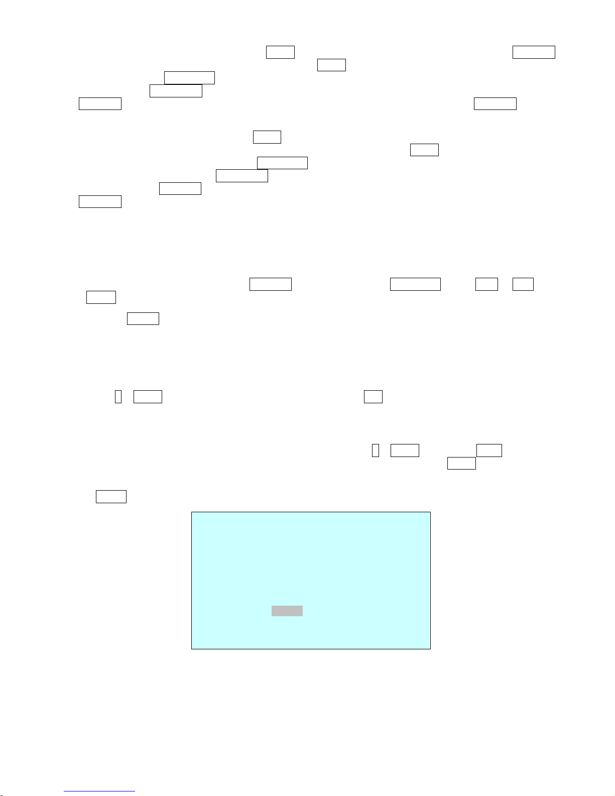
3.4 Auto Scan
(Shortcut:
SCAN
)
The Auto scan supports up to 17 programmed angles at user-programmable speeds. Follow these steps
to program Auto Scan:
NUMBER
:01 -08, 10-17, 09:AUTO PAN mode
TITLE
:up to 12 characters.
MODE
:NORMAL, VECTOR, RANDOM (AUTO PAN mode :NORMAL, RANDOM only)
NORMAL: Move from start point to end point in panning only.
VECTOR: Move from start point to end point including tilt and zoom simultaneously and
linearly. In some model, the zoom is fixed at wider angle and the zoom magnification
information is not displayed.
RANDOM: Move randomly between the start point and the end point.
SPEED
: 1 - 13 step, the lower number means the slower speed.
SCAN DIR
: Set the scan direction, CCW(Counter Clock Wise), CW(Clock Wise)
SWAP
: Swap the start point for the end point.
DWELL
: Set the dwell time at the both end, 01 – 99 seconds
1. Press the
SCAN
key to enter the auto scan menu directly. Or press the
MENU
key to display the main
menu on the monitor. Scroll to Auto Scan and push the
Joystick
to the right.
2. Select the” NUMBER” and set the desired number by pushing the
Joystick
left or right.
3. Select the “TITLE” and twist the
Joystick
to enter the title edit mode.
4. Twist the
Joystick
by changing the alphanumeric characters and move the next position. Or move
down to the character table and press
CTRL
or
IRIS OPEN
at the desired character then the cursor
position moves to the next position automatically. Push the
Joystick
left or right at the “ALL DELETE”
field to delete all characters. Push the
Joystick
left or right at the “EXIT” field to finish title edit menu.
5. Select “MODE” and “SPEED”.
AUTO SCAN SETUP
NUMBER : 01
TITLE : A01
MODE : NORMAL
SPEED : 5 STEP
START ANGLE : ----- ----- --END ANGLE : ----- ----- --SCAN DIR : CCW
SWAP : OFF
DWELL : 03 SEC
SAVE AND EXIT(ESC TO CANCEL)
TITLE EDIT MENU
A01
*
A B C D E F G H I J
K L M N O P Q R S T
U V W X Y Z 0 1 2 3
4 5 6 7 8 9 ( )
ALL DELETE
EXIT (ESC TO EXIT)
6. Select “START ANGLE”. Hold down the
CTRL
key while selecting the start position using the
Joystick
.
Current panning position will be displayed. Release
CTRL
key to complete the selection of the start
position. Or Press
IRIS Open
then the “CTRL” displays. Move the desired position and the zoom
position. Press
IRIS Close
then the “CTRL” disappears. To adjust at the 0.1 degree interval, twist the
Joystick
at the pan field and the tilt field. To adjust at the one zoom interval, twist the
Joystick
at the
zoom field.
7. Select “END ANGLE.” Hold down the
CTRL
key while moving the Joystick to select the end position.
The end position angle should be larger than start position. Release the
CTRL
key to complete the
selection of the end position. Or Press
IRIS Open
then the “CTRL” displays. Move the desired position
and the zoom position. Press
IRIS Close
then the “CTRL” disappears. To adjust at the 0.1 degree
interval, twist the
Joystick
at the pan field and the tilt field. To adjust at the one zoom interval, twist the
Joystick
at the zoom field.
8. Set “SCAN DIR” to CCW or CW.
9. Select “SWAP”. Set to ON, to exchange the start angle and the end angle.
10. Set “DWELL TIME”.
11. Select Save and Exit and push the
Joystick
to the right or press
IRIS Open
. Press
ESC or IRIS
Close
to exit the program without saving.
Pressing the
HOME
key delete stored data at the angle field.
To set the position using the preset position:
a. Before entering the Auto Scan menu, select a preset position as a starting point for
Auto Scan.
Example: 2
+
PRST
and do step 1 to 4. In step 5, just press the
Ctrl
key at the start angle position, the
current position will be displayed as a start position.
b. Save and exit from the menu.
c. In normal mode, call a preset to be the end point of scan. Press 3 +
PRST
then press
Scan
key to
enter the Auto Scan menu. Move the cursor position to END ANGLE. Just press
CTRL
key at the end
angle position. Save and exit from the menu.
Press
SCAN
key on the angle field to display with the small OSD. Then the screen will show as below.
The setting procedure is the same as above.
NOTE: 09:AUTO-PAN mode(Endless panning)
AUTO SCAN AREA SETUP
(CTRL KEY)
NUMBER01
START: ----- ----- --END : ----- ----- --EXIT(ESC TO EXIT)
3.5 Preset
(Shortcut:
PRST
)
If you need to view specific places routinely, you should program presets. A preset is a programmed video
scene with automatic pan, tilt, zoom, focus, and AE settings. Once programmed, placing the number
position and pressing a
PRST
button on your controller calls up that preset automatically. In addition,
presets may be assigned to alarm actions or
as the “home” position for the dome camera. As many as 240 presets, whose positions are saved in the
dome’s firmware, may be programmed.
There are three pages of preset menu. Each page has 80 presets. Pages can be scrolled
by pushing the
Joystick
to the Left or Right on the first or last No. of Preset.
-
: blank preset position
* : position has the preset
█ : Current cursor position
Follow steps below to store the Preset positions:
1. Press the
PRST
key to enter the preset menu directly. Or press the
MENU
key to display the main
menu on the monitor. Scroll to preset and push the
Joystick
to the right.
2. Select the blank preset position to be stored by pushing the
Joystick
up, down, right,
or left.
3. After selecting a blank position, press and hold
CTRL
, Use the
Joystick
to control the direction of the
camera and lens.
4. After aiming the camera (view direction and lens control), release
CTRL
. The cursor will be on the Title
then twist the
Joystick
handle or Press
Tele
or
Wide
Key to edit the preset title. Follow the procedure
of the auto scan above to edit titles.
5. Select “CAMERA SET” and pushing the
Joystick
left or right. Then the preset camera setup displays.
PRESET CAMERA SETUP
FOCUS : AUTO
MOTION : OFF
MOTION SETUP
AE SETUP
SAVE AND EXIT(ESC TO CANCEL)
Set FOCUS: AUTO, MANUAL, ONE PUSH
Set MOTION: OFF, ON
Select “MOTION SETUP” and pushing the Joystick left or right. Then the MOTION setup displays.
PRESET SETUP
NUMBER : 001
TITLE : --CAMERA SET
DWELL : --- SEC
12345678901234567890
00 █**----------------02 -------------------04 -------------------06 --------------------
NEXT PAGE
SAVE AND EXIT(ESC TO CANCEL)
MOTION SETUP
SENSITIVITY : 12
POSITION : ALL
DELAY : 00 SEC
OUTPUT : OFF
HOLD TIME : 03 SEC
EXIT(ESC TO EXIT)
Set SENSITIVITY: 1~10(22X model) / 1~15(36X model)
Set POSITION: ALL, CENTER
Set DELAY: 0~5 SEC
Set OUTPUT: OFF, OUT1
Set HOLD TIME: 3~99 SEC
Select “AE SETUP” and pushing the
Joystick
left or right. Then the AE setup displays. Refer to the AE
SETUP in the camera setup.
6. Set “DWELL TIME”(03-99second)
7. To select the next page of presets, scroll the page by pushing the
Joystick
to the Left
on the first and last columns of the menu.
8. Repeat steps 2 through 7 for each additional preset position.
9. Select Save and Exit by pushing the Joystick to the right. Press ESC to exit the Preset menu without
saving.
NOTE: Press the HOME key at programmed preset position(*) to delete a programmed preset view.
The position, which is marked with *, already has the preset view assigned. To review the stored preset,
press
PRST
key on the *,The camera will show the stored preset scene.
Hold down the
CTRL
key while selecting the desired scene using the
Joystick
. Current position will be
displayed. Release
CTRL
key to complete. Or Press
IRIS Open
then the “CTRL” displays. Move the
desired position and the zoom position. Press
IRIS Close
then the “CTRL” disappears. Select Exit and
push the
Joystick
to the right.
3.6 Shortcut of Preset Program
After selecting the desired scene, press No. (1 to
240
), and press
CTRL
and
PRST
subsequently. The
current view will be stored to the selected preset number if the preset number is empty. If selected preset
number is not empty, “
OVER WRITE
” message will be displayed on the monitor and select the “OK” and
push the
Joystick
to the right to overwrite.
Example: 1 , 0 , 1
+
CTRL
+
PRST
will store current view as preset No.
101
. In this case, focus will be
programmed as Auto, dwell time will be set to 3 second, and the current AE mode will be programmed.
PRESET AREA SETUP
(CTRL KEY)
NUMBER 001
PAN TILT
000.0 000.0
EXIT(ESC TO EXIT)
3.7 Tour
(SHORTCUT:
TOUR)
There are 8 programmable Tours. Each Tour consists of up to 42 Preset positions, Patterns, Scans or
other Tours (second-level). Using second-level tours, it can be expanded to over 300 functions in a single
tour.
--- : blank position
SCAN TYPE : NORMAL/ VECTOR
DWELL : 03-99 Sec
003 : Preset (1~240)
A08 : Auto Scan (1~8,10~17)
P01 : Pattern (1~8)
T02 : Tour (1~8)
Follow the steps below to program the Tours:
1. Press
MENU
to display the main menu on the monitor. Scroll to Tour and push the
Joystick
to the
right to enter the Tour menu. Or just press the
TOUR
key on the keyboard.
2. Select the” NUMBER” and set the desired number by pushing the
Joystick
left or right.
3. Choose a blank position to be programmed by pushing the
Joystick
up, down, right,
or left.
4. To add a stored preset, twist the
Joystick
then the stored preset number displays.
5. To place functions other than preset, press
TOUR, PTRN
, or
SCAN
for Tour, Pattern
or Auto Scan respectively.
6. You can also overwrite the programmed number and to remove a stored number from the Tour, press
the
HOME
key on the stored number, a blank position mark (---) will be displayed.
7. Repeat Step 2 through 5 for each desired position. Each title will be displayed on top
of the line.
8. To edit the title, follow the procedure of the auto scan above to edit titles
9. Select Save and Exit and push the
Joystick
to the right. Press
ESC
to exit the program without
saving.
You can expand the Tour sequence by calling other programmed tours.
NOTE: The speed applies in the vector mode only.
NOTE: In the Tour mode, in conjunction with preset and Auto Scan, you can make the camera travel from a
preset position to another preset position at a specific speed.
TOUR SETUP
NUMBER : 01
TITLE : T01
SCAN TYPE : NORMAL
SPEED : 5 STEP
DWELL : -- SEC
003 A08 --- --- --- --- ---
--- --- --- --- --- --- ---
--- --- P01 --- --- --- ---
--- T02 --- --- --- --- ---
--- --- --- --- --- --- ---
--- --- --- --- --- --- ---
SAVE AND EXIT(ESC TO CANCEL)
Example
: Preset 001>002>003>004>005>006, Auto Scan 01 starts at preset 002, ends at preset 003,
Auto Scan 02 starts at preset 005, ends at preset 006; Tour 001, 002, A01, 004, A02.
1 2 2~3 4 5~6, repeat
where : Quick move, ~ : Programmed speed
To change the dwell time of the preset in the tour:
Use the
Joystick
to move the cursor to a stored preset position. By pressing
PRST
key, the camera will
move to the stored Preset view and the cursor moves to the dwell time field. After changing the dwell time,
press
PRST
key and the cursor moves to the preset number.
To assign the functions other than preset in the tour when the function key is not existed:
Use the
Joystick
to move the cursor to a stored preset position. Pressing
CTRL
key or
IRIS OPEN
key will change the preset number to other function (auto scan, pattern, tour, preset) with the
first programmed number. To change the number, twist the joystick or press
Tele
or
Wide
key.
3.8 Pattern
(Shortcut:
PTRN
)
The Pattern feature records user control of the selected dome camera. Up to four 8 patterns can be stored
and played back by pressing No.+
PTRN
keys subsequently.
Follow steps below to program the Pattern:
1. Press
MENU
to display the main menu on the monitor. Scroll to Pattern and push the
Joystick
to the
right to enter the pattern menu. Or just press the
PTRN
key on the keyboard.
2. Select the desired pattern to be programmed by pushing the
Joystick
Up or Down. If the pattern is
not 000, a pattern has already been recorded. Patterns can be overwritten.
3. Press and hold down the
CTRL
key while controlling the camera direction and zoom with the
Joystick
. The dome will be automatically recorded until you release the
CTRL
key. Or Press
IRIS
Open
then the “CTRL” displays. Move the position and the zoom position. Press
IRIS Close
then
the “CTRL” disappears.
4. Select Save and Exit and push the
Joystick
to the right. Press
ESC
to exit the program without
saving.
5. To edit the title, follow the procedure of the auto scan above to edit titles.
NOTE:
Press the HOME key at any programmed position to delete the pattern.
NOTE: If total recording time reaches 500 seconds, it will automatically stop for a moment.
PATTERN SETUP
(CTRL KEY)
NO TITLE SEC PERCENT
01 : P01 000 00.0%
02 : P02 000 00.0%
03 : P03 000 00.0%
04 : P04 000 00.0%
05 : P05 000 00.0%
06 : P06 000 00.0%
07 : P07 000 00.0%
08 : P08 000 00.0%
TOTAL 0000 00.0%
SAVE AND EXIT(ESC TO CANCEL)
Press
PTRN
key on the title field to display with the small OSD. Then the screen will show
as below.
The setting procedure is the same as above.
3.9 Area Title
Enter a specific name on programmed angle between START and END. For the screen below, when the
camera points at an angle between 124.3° (PAN), 30.7° (TILT) to 359.5° (PAN), 45.4° (TILT), ABC will
be displayed on the screen.
NUMBER
:01 - 16
TITLE
:up to 12 characters.
SWAP
: Swap the start point for the end point.
1 . Select the” NUMBER” and set the desired number by pushing the
Joystick
left or right.
2. To edit the title, follow the procedure of the auto scan above to edit titles.
3. Select “START ANGLE”. Hold down the
CTRL
key while selecting the start position using the
Joystick
.
Current panning position will be displayed. Release
CTRL
key to complete the selection of the start
position. Or Press
IRIS Open
then the “CTRL” displays. Move the desired position. Press
IRIS Close
then the “CTRL” disappears. To adjust at the 0.1 degree interval, twist the
Joystick
at the pan field and
the tilt field.
4. Select “END ANGLE.” Hold down the
CTRL
key while moving the Joystick to select the end position.
Release the
CTRL
key to complete the selection of the end position.
Or Press
IRIS Open
then the “CTRL” displays. Move the desired position. Press
IRIS Close
then the
“CTRL” disappears. To adjust at the 0.1 degree interval, twist the
Joystick
at the pan field and the tilt
field.
5. Select “SWAP”. Set to ON, to exchange the start angle and the end angle.
6. Select Save and Exit and push the
Joystick
to the right or press
IRIS Open
. Press
ESC or IRIS
Close
to exit the program without saving.
PATTERN AREA SETUP
(CTRL KEY)
NUMBER 01
000 00.0%
0001 01.0%
EXIT(ESC TO EXIT)
AREA TITLE SETUP
NUMBER : 01
TITLE : ABC
START ANGLE : 124.3 30.7
END ANGLE : 359.5 45.4
SWAP : OFF
SAVE AND EXIT(ESC TO CANCEL)
3.10 Privacy Zone
Hide up to 8 unwanted scenes in a camera.
PRIVACY ZONE SETUP
(CTRL KEY)
NO TITLE METHOD
01 ABC ON BLOCK
02 DEF ON V.OFF
03 OFF ---04 OFF ---05 OFF ---06 OFF ---07 OFF ---08 OFF ----
SAVE AND EXIT(ESC TO CANCEL)
1. Place the cursor at the title field.
2. Holding down the
CTRL
key displays the privacy area menu while selecting the position using the
Joystick
. Current position will be displayed. Release
CTRL
key to complete the selection of the
position.
Or Press
IRIS Open
then the privacy area menu displays. Move the desired position. Press
IRIS
Close
then the “CTRL” disappears and returns to the previous menu.
3. Place the cursor at the title field. Twist the
Joystick
to enter the title edit mode. Follow the procedure
of the auto scan above to edit titles.
4. To turn the stored zone On or Off, twist the
Joystick
handle or press
Tele
or
Wide
Key.
5. Set the method, “BLOCK” or “V.OFF(video off)”
6. Select the Save and Exit option by pushing the
Joystick
up or down. Save and exit the program by
pushing the
Joystick
to the right. Press
ESC
to exit the program without saving.
Press the
HOME
key to delete programmed privacy zone at the title field.
PRIVACY AREA MENU
(CTRL KEY)
CONTROL
NUMBER 001
354.8 344.8

3.11 Camera Menu Type 1
NOTE: The features will vary depending on the camera module installed in your dome camera.
CAMERA SETUP
FOCUS CONTROL
WB CONTROL
AE CONTROL
CAMERA CONTROL
EXIT(ESC TO EXIT)
• FOCUS CONTROL
MODE
AUTO / MANUAL / ONE PUSH / CONSTANT MANUAL
Use manual mode in normal use.
AF SENSITIVITY
NORMAL / LOW
NORMAL: Use this option when shooting fast motion.
LOW: Offers better focus stability. In low luminance conditions, Auto Focus stops
operation even when brightness changes, enabling stable images of moving
objects.
FOCUS LIMIT
This distance is approximate value and the focus operate from the setting value.
CAUTION: Avoid continuous, 24-hour use of the auto focus. This will shorten the lifespan of the
lens.
• WB (White Balance) CONTROL
MODE
AUTO / INDOOR / OUTDOOR / ONE PUSH / ATW / MANUAL / OUTDOOR AUTO
/ SODIUM AUTO / SODIUM
AUTO Computes the white balance value output using color information
from the entire screen automatically. (3000 to 7500 °K)
INDOOR 3200 K base mode
OUTDOOR 5800 K base mode
ONE PUSH One push WB mode is a fixed mode that may be automatically readjusted at the
stop after moving.
ATW Auto tracing white balance. (2000 to 10000° K)
MANUAL Control of R and B gain
OUTDOOR AUTO Auto mode specifically for outdoors.
SODIUM AUTO Auto mode that is compatible with sodium vapor lamps
SODIUM Fixed mode specifically for sodium vapor lamps
RGAIN
0 ~ 255
BGAIN
0 ~ 255
RGAIN / BGAIN modes are controllable only in MANUAL Mode
FO
CUS SETUP
MODE : AUTO
AF SENSITIVITY : LOW
FOCUS LIMIT : 29CM
SAVE AND EXIT(ESC TO CANCEL)
WB SETUP
MODE : ATW
R GAIN : 213
B GAIN : 174
SAVE AND EXIT(ESC TO CANCEL)

• AE CONTROL
MODE
AUTO / MANUAL / SHUTTER PRIO / IRIS PRIO / BRIGHT
AUTO Auto Iris and Gain, Fixed Shutter speed
(NTSC: 1/60 sec, PAL: 1/50 sec)
MANUAL Variable Shutter, Iris and Gain.
SHUTTER PRIO Variable Shutter speed, Auto Iris and Gain.
IRIS PRIO Variable Iris, Auto Gain and Shutter speed.
BRIGHT Variable Iris and Gain
SLOW SHUTTER
ON/OFF
IRIS
CLOSE / F28 / F22 / F19 / F16 / F14 / F11 / F9.6 / F8.0 / F6.8 / F5.6 / F4.8 / F4.0 /
F3.4 / F2.8 / F2.4 / F2.0 / F1.6
GAIN
0 / 2 / 4 / 6 …… / 28 / -3 DB
BRIGHT
0, 1,2, 3, 4 ..... 29, 30,31
SHUTTER
1/1 , 1/2 , 1/4(3), 1/8(6). .. 1/4000(3500), 1/6000, 1/10000
BACK LIGHT
Objects in front of bright backgrounds will be clearer with BLC ON.
NIGHT SHOT
AUTO,ON,OFF,GLOBAL
WDR
ON,OFF
SLOW RESPONSE
1-32
NOTE: Values in ( ) are for PAL Camera.
NOTE:
The Back Light operates in AUTO mode only.
For example, if you change the back light to ON, the camera will change AE mode to “AUTO”.
The NIGHT SHOT option removes the IR cutoff filter of the camera and makes the camera sensitive to
near infrared.
AUTO
Camera goes in to B&W mode at low light.
GLOBAL
Controlled by the keyboard.
The operator can enable NIGHT SHOT for all dome cameras at the same time.
If the NIGHT SHOT mode is set to GLOBAL, “999” +
ENTR
will turn Off the NIGHT SHOT mode and
“888” +
ENTR
will turn On the NIGHT SHOT mode.
ON
: B/W mode.
OFF
: Color mode.
NOTE : Selecting the Night Shot to Auto mode will change AE mode to “AUTO”.
SLOW RESPONSE
The slow response function allows you to lengthen the automatic exposure response speed from 1 up to
32 times. For example, with the normal setting (about 1 second), if the headlights of a car are caught by
the camera, the camera automatically adjusts the exposure so that it can shoot a high-intensity subject (in
this case, the headlights). As a result, images around the headlights, that is, the rest of the subject, except
the headlights, becomes relatively dark, and poorly distinguished. However, using the slow response
function can still easily distinguish the portions of the image surrounding the headlights.
AE SETUP
MODE : MANUAL
SLOW SHUTTER : --IRIS : F5.6
GAIN : 0 DB
BRIGHT : AUTO
SHUTTER : 1/60
BACK LIGHT : OFF
NIGHT SHOT : AUTO
WDR : OFF
SLOW RESPONSE: 1
SAVE AND EXIT(ESC TO CANCEL)
 Loading...