

XIMEA xiX MX089MG-SY-X2G2, xiX MX023CG-SY-X2G2, xiX MX031MG-SY-X2G2, xiX MX050CG-SY-X2G2, xiX MX089CG-SY-X2G2 Technical Manual
...
xiX
[ksi-x: or sai-ex:]
• PCI Express cameras for integration
Technical Manual
Version 1.3, August, 2018

1. Introduction
1.1. About This Manual
Dear customer,
Thank you for purchasing a product from XIMEA.
We hope that this manual can answer your questions, but should you have any further questions or if you wish to c laim a
service or warranty case, please contact your local dealer or refer to XIMEA Support on our website:www.ximea.com/support
The purpose of this document is to provide a description of the XIMEA xiX-Series cameras and to descri be t he correct way to
install related software and drivers and run it successfully. Please read this manual thoroughly before operating your new
camera for the first time. Please follow all instructions and observe the warnings.
This docu ment is su bjec t to change without notice.
1.2. About XIMEA
XIMEA is one of the worldwide leaders for innovative cam era solutions with a 20-year history of research, develo pment and
product ion of digital image acquisition syst ems. Based in Slovakia, Germany and the US and w ith a global distrib uto r network ,
XIMEA offers their cameras worldwi de. In close collaboration with customers XIMEA has deve loped a broad spectr um of
technologies and cutting-edge, h ighly com petitive product s .
XIMEA's camera centric technolo gy portfolio comprises a broad spect rum of digital technologies, from data interfaces such as
PCI express, USB 2.0, 3.0 and USB 3.1, t o cooled digital cameras with CCD and CMOS sensors, as well as X-ray came ras.
XIMEA has t hree di vis ions – generic machine vision and integrated vision s ystems, scientific imaging and OEM/custom.
XIMEA ca meras find use in many industrial applications, such as motion control, robotics , or quality cont rol in m anufacturing.
The broad spectrum of came ras also includes thermall y stabilized X-ray cameras, and specialty cameras for me dical
applications, research, surveillance and defense.
1.2.1. Contact XIMEA
XIMEA is a worldwi de operating Company
Headquarters, S ales worldwide
XIMEA GmbH
Am Mittelhafen 16
48155 Münster
Germany
Tel: +49 (251) 202 408-0
Fax: +49 (251) 202 408-99
Internet www.ximea.com
General inquiries info@ximea.com
Sales sales@ximea.com
Support support@ximea.com
Sales America
XIMEA Corp.
8725 W 14th Ave, Ste 110
Lakewood, CO 80215
USA
Tel: +1 (303) 389-9838
Fax: +1 (303) 202-6350
R&D, Production
XIMEA s.r.o.
Lesna 52
900 33 Marianka
Slovakia
xiX - Technical Manual Ve rsio n 1.3 2

1.3. Standard Conformity
The xiX ca meras have been tes ted using the following eq uipment:
• List equipment: To be added
1.3.1. CE Conformity
To be added
1.3.2. For customers in the US: FCC Conformity
To be added
1.3.3. For customers in Canada
The xiX cameras comply with the Class A limits for radio noise emissions set out in Radio Interference Regulations.
xiX - Technical Manual Ve rsio n 1.3 3

1.3.4. RoHS Conformity
The xiX cameras comply with the requirements of the RoHS (Restriction of Hazardous Substances) Directive 2011/65/EU.
1.3.5. WEEE Conformity
The xiX cameras comply with the requirements of the WEEE (waste electrical and electronic equipment) Directive 2003/108/EC.
1.3.6. GenICam GenTL API
GenICam standard transport layer interface, gra bbing images.GenICam/GenTL provides an agnostic transport layer interface
to acquire images o r other data and to com municate with a device. Each XIMEA camer a can be GenTL Producer.
1.4. Helpful Links
• XIMEA Homepage http://www.ximea.com/
• PCIe zone https://www.ximea.com/en/pci-express-camera/pcie-camera-zone
• xiAPI stable versions download https://www.ximea.com/support/documents/4
• xiAPI beta versions download https://www.ximea.com/support/documents/14
• Frequently Asked Questions http://www.ximea.com/support/wiki/allpr o d/Frequently_Asked_Questions
• Knowled g e Base http://www.ximea.com/support/wiki/allprod/Knowledge_Base
• Vision Libraries http://www.ximea.com/support /projects/vision-libraries/wiki
• XIMEA Registration http://www.ximea.com/en/products/register
• XIMEA Live Support http://www.ximea.com/support/wiki/allprod/XIMEA_Live_Support
• XIMEA General Terms & Conditions http://www.ximea.com/en/corporate/generaltc
xiX - Technical Manual Ve rsio n 1.3 4

1.5. Table of Contents
1. Introduction ................................................................................................................................................................ 2
1.1. About This Manual ............................................................................................................................................. 2
1.2. About XIMEA ..................................................................................................................................................... 2
1.2.1. Contact XIMEA .......................................................................................................................................... 2
1.3. Standard Conformity .......................................................................................................................................... 3
1.3.1. CE Conformity ........................................................................................................................................... 3
1.3.2. For customers in the US: FCC Conformity ................................................................................................... 3
1.3.3. For customers in Canada ........................................................................................................................... 3
1.3.4. RoHS Conformity ....................................................................................................................................... 4
1.3.5. WEEE Conformity ...................................................................................................................................... 4
1.3.6. GenICam GenTL API .................................................................................................................................. 4
1.4. Helpful Links...................................................................................................................................................... 4
1.5. Table of Contents ............................................................................................................................................... 5
2. xiX Camera Series .................................................................................................................................................... 11
2.1. What is xiX ...................................................................................................................................................... 11
2.2. Advantages ..................................................................................................................................................... 11
2.3. PCI Express Vision Camera Applications ............................................................................................................ 12
2.4. Common features ............................................................................................................................................ 12
2.5. What is xSWITCH ............................................................................................................................................. 13
2.5.1. xSWITCH examples ................................................................................................................................. 15
2.6. Model Nomenclature ........................................................................................................................................ 16
2.7. Models Overview, sensor and models................................................................................................................ 17
2.8. Accessories ..................................................................................................................................................... 18
3. Hardware Specification ............................................................................................................................................. 19
3.1. Power Supply .................................................................................................................................................. 19
3.2. General Specification ....................................................................................................................................... 19
3.2.1. Environment ........................................................................................................................................... 19
3.2.2. Firmware / Host driver / API features ........................................................................................................ 19
3.3. Mounting points ............................................................................................................................................... 20
3.4. Lens Mount ..................................................................................................................................................... 21
3.4.1. Screws ................................................................................................................................................... 22
3.5. Optical path ..................................................................................................................................................... 23
3.5.1. Filter glasses .......................................................................................................................................... 23
3.5.2. Monochrome and near infrared extended camera models (MX X2G2 models only) ...................................... 23
3.5.3. Color camera models (MX X2G2 models only) ........................................................................................... 24
3.6. Model Specific Characteristics .......................................................................................................................... 25
3.6.1. MX023xG-SY-X2G2-Fx............................................................................................................................ 25
3.6.1.1. Sensor and camera parameters ................................................ ...................................................... 25
3.6.1.2. Quantum efficiency curves [%] ........................................................................................................ 26
3.6.1.3. Drawings MX023xG-SY-X2G2-FL (C-mount [with C/CS mount module B]) ......................................... 27
3.6.1.4. Drawings MX023xG-SY-X2G2-FV (C-mount [with C/CS mount module B]) ......................................... 27
3.6.1.5. Referenced documents ................................................................................................................... 28
3.6.1.6. Sensor features .............................................................................................................................. 28
3.6.2. MX031xG-SY-X2G2-Fx............................................................................................................................ 29
3.6.2.1. Sensor and camera parameters ................................................ ...................................................... 29
xiX - Technical Manual Ve rsio n 1.3 5

3.6.2.2. Quantum efficiency curves [%] ........................................................................................................ 30
3.6.2.3. Drawings MX031xG-SY-X2G2-FL (C-mount [with C/CS mount module B]) ......................................... 31
3.6.2.4. Drawings MX031xG-SY-X2G2-FV (C-mount [with C/CS mount module B]) ......................................... 31
3.6.2.5. Referenced documents ................................................................................................................... 32
3.6.2.6. Sensor features .............................................................................................................................. 32
3.6.3. MX050xG-SY-X2G2-Fx............................................................................................................................ 33
3.6.3.1. Sensor and camera parameters ................................................ ...................................................... 33
3.6.3.2. Quantum efficiency curves [%] ........................................................................................................ 34
3.6.3.3. Drawings MX050xG-SY-X2G2-FL (C-mount [with C/CS mount module B]) ......................................... 35
3.6.3.4. Drawings MX050xG-SY-X2G2-FV (C-mount [with C/CS mount module B]) ......................................... 35
3.6.3.5. Referenced documents ................................................................................................................... 36
3.6.3.6. Sensor features .............................................................................................................................. 36
3.6.4. MX089xG-SY-X2G2-Fx............................................................................................................................ 37
3.6.4.1. Sensor and camera parameters ................................................ ...................................................... 37
3.6.4.2. Quantum efficiency curves [%] ........................................................................................................ 38
3.6.4.3. Drawings MX089xG-SY-X2G2-FL (C-mount [with C/CS mount module B]) ......................................... 39
3.6.4.4. Drawings MX089xG-SY-X2G2-FV (C-mount [with C/CS mount module B]) ......................................... 39
3.6.4.5. Referenced documents ................................................................................................................... 40
3.6.4.6. Sensor features .............................................................................................................................. 40
3.6.5. MX124xG-SY-X2G2-Fx............................................................................................................................ 41
3.6.5.1. Sensor and camera parameters ................................................ ...................................................... 41
3.6.5.2. Quantum efficiency curves [%] ........................................................................................................ 42
3.6.5.3. Drawings MX124xG-SY-X2G2-FL (C-mount [with C mount module B]) .............................................. 43
3.6.5.4. Drawings MX124xG-SY-X2G2-FV (C-mount [with C mount module B]) .............................................. 43
3.6.5.5. Referenced documents ................................................................................................................... 44
3.6.5.6. Sensor features .............................................................................................................................. 44
3.6.6. MX120xG-CM-X4G2-Fx .......................................................................................................................... 45
3.6.6.1. Sensor and camera parameters ................................................ ...................................................... 45
3.6.6.2. Quantum efficiency curves [%] ........................................................................................................ 46
3.6.6.3. Drawings MX120xG-CM-X4G2-FL................................................................................................... 47
3.6.6.4. Drawings MX120xG-CM-X4G2-FV .................................................................................................. 47
3.6.6.5. Referenced documents ................................................................................................................... 48
3.6.6.6. Sensor features .............................................................................................................................. 48
3.6.7. MX200xG-CM-X4G2-Fx .......................................................................................................................... 49
3.6.7.1. Sensor and camera parameters ................................................ ...................................................... 49
3.6.7.2. Quantum efficiency curves [%] ........................................................................................................ 50
3.6.7.3. Drawings MX200xG-CM-X4G2-FL................................................................................................... 51
3.6.7.4. Drawings MX200xG-CM-X4G2-FV .................................................................................................. 51
3.6.7.5. Referenced documents ................................................................................................................... 52
3.6.7.6. Sensor features .............................................................................................................................. 52
3.6.8. MX500xG-CM-X4G2-Fx .......................................................................................................................... 53
3.6.8.1. Sensor and camera parameters ................................................ ...................................................... 53
3.6.8.2. Quantum efficiency curves [%] ........................................................................................................ 54
3.6.8.3. Drawings MX500xG-CM-X4G2-FL................................................................................................... 55
3.6.8.4. Drawings MX500xG-CM-X4G2-FV .................................................................................................. 55
3.6.8.5. Referenced documents ................................................................................................................... 56
xiX - Technical Manual Ve rsio n 1.3 6

3.6.8.6. Sensor features .............................................................................................................................. 56
3.7. User interface – LEDs ...................................................................................................................................... 57
3.8. xiX X2G2 Interface connector ............................................................................................................................ 58
3.8.1. Interface connector location ..................................................................................................................... 58
3.8.2. Pinning ................................................................................................................................................... 58
3.8.3. Inserting / detaching FPC cable................................................................................................................ 59
3.9. xiX X4G2 Interface connector ............................................................................................................................ 62
3.9.1. Interface connector location ..................................................................................................................... 62
3.9.2. Pinning ................................................................................................................................................... 62
3.9.3. Inserting / detaching FFC cable ................................................................................................................ 64
3.10. xiX Digital Input / Output (GPIO) Interface ........................................................................................................... 66
3.10.1. Optically isolated Digital Input .................................................................................................................. 66
3.10.1.1. Digital Input – signal levels ............................................................................................................. 66
3.10.1.2. Digital Input – Internal Schematic .................................................................................................... 67
3.10.1.3. Digital Input – Wiring ...................................................................................................................... 67
3.10.1.4. Digital Input – Timing ..................................................................................................................... 68
3.10.2. Optically isolated Digital Output ................................................................................................................ 68
3.10.2.1. Optically isolated Digital Output - General info .................................................................................. 68
3.10.2.2. Optically isolated Digital Output Delay .............................................................................................. 68
3.10.2.3. Optically isolated Digital Output – Internal schematic ........................................................................ 69
3.10.2.4. Digital Output – Wiring ................................................................................................................... 69
3.10.2.5. Digital Output – Timing ................................................................................................................... 74
3.10.3. Non-isolated Digital Lines ........................................................................................................................ 75
3.10.3.1. Non-isolated Digital Input/Output (INOUT) General info ...................................................................... 75
3.11. Heat Dissipation ............................................................................................................................................... 76
3.12. CBL-MX-X2G2-0M07/ CBL-MX-X2G2-0M10/ CBL-MX-X2G2-0M25/ CBL-MX-X2G2-0M50 ................................ 76
3.13. CBL-MX-X4G2-0M10 / CBL-MX-X4G2-0M25 / CBL-MX-X4G2-0M50 ................................................................ 76
3.14. MX camera adapters ........................................................................................................................................ 77
3.15. Tripod Adapter ................................................................................................................................................. 78
3.15.1. Tripod Adapter MX X2G2 (MECH-MC-BRACKET-KIT) ................................................................................. 78
3.15.2. Drawings ................................................................................................................................................ 78
3.15.3. Tripod Adapter MX X4G2 ......................................................................................................................... 79
3.15.4. Drawings ................................................................................................................................................ 79
3.16. xiX X4G2 Lens adapter – MECH-60MM-EF-ADAPTER ........................................................................................ 80
4. Operation ................................................................................................................................................................. 81
4.1. System Requirements ...................................................................................................................................... 81
4.1.1. Software Requirements ........................................................................................................................... 81
4.1.2. Hardware Requirements .......................................................................................................................... 81
4.1.2.1. System Configuration ..................................................................................................................... 81
4.2. Video Formats ................................................................................................................................................. 83
4.2.1. Full Resolution ........................................................................................................................................ 83
4.2.2. ROIs – Region Of Interest ........................................................................................................................ 83
4.2.3. Downsampling Modes ............................................................................................................................. 83
4.2.3.1. Binning .......................................................................................................................................... 83
4.2.3.2. Skipping ........................................................................................................................................ 83
4.2.4. Image Data Output Formats ..................................................................................................................... 84
xiX - Technical Manual Ve rsio n 1.3 7

4.2.5. Digitization bit depth................................................................................................................................ 85
4.3. Acquisition modes............................................................................................................................................ 86
4.3.1. Free-Run ................................................................................................................................................ 86
4.3.2. Triggered Acquisition .............................................................................................................................. 86
4.3.2.1. Software Trigger ............................................................................................................................ 86
4.3.2.2. Hardware Trigger ........................................................................................................................... 86
4.3.2.3. Triggered acquisition - single frame ................................................................................................ 87
4.3.2.4. Triggered acquisition - burst of frames ............................................................................................ 88
4.3.2.5. Exposure defined by trigger pulse length.......................................................................................... 88
4.3.2.6. Multiple exposures in one frame...................................................................................................... 89
4.4. Camera Parameters and Features ..................................................................................................................... 90
4.4.1. Exposure Time ........................................................................................................................................ 90
4.4.2. Gain ....................................................................................................................................................... 90
4.5. Host-Assisted Image Processing Parameters Available in xiAPI. .......................................................................... 90
4.5.1. Auto Exposure – Auto Gain ...................................................................................................................... 90
4.5.2. White Balance ........................................................................................................................................ 90
4.5.2.1. Assisted Manual White Balance ...................................................................................................... 90
4.5.2.2. Auto White Balance ........................................................................................................................ 90
4.5.3. Gamma .................................................................................................................................................. 90
4.5.4. Sharpness .............................................................................................................................................. 90
4.5.5. Color Correction Matrix ............................................................................................................................ 91
4.5.6. Sensor Defect Correction ......................................................................................................................... 91
4.5.7. HDR ....................................................................................................................................................... 92
5. Software .................................................................................................................................................................. 95
5.1. Accessing the Camera ..................................................................................................................................... 95
5.1.1. Proprietary API ........................................................................................................................................ 95
5.1.2. Standard Interface .................................................................................................................................. 95
5.1.2.1. GenICam ....................................................................................................................................... 95
5.1.3. Vision Library Integration ..................................................................... .................................................... 95
5.2. XIMEA CamTool ............................................................................................................................................... 96
5.3. Supported Vision Libraries ................................................................................................................................ 98
5.3.1. Libraries maintained by XIMEA ................................................................................................................. 98
5.3.1.1. MathWorks MATLAB ...................................................................................................................... 98
5.3.1.2. MVTec HALCON ............................................................................................................................. 98
5.3.1.3. National Instruments LabVIEW Vision Library .................................................................................... 98
5.3.1.4. OpenCV ......................................................................................................................................... 98
5.4. XIMEA Windows Software Package ................................................................................................................... 99
5.4.1. Contents................................................................................................................................................. 99
5.4.2. Installation .............................................................................................................................................. 99
5.5. XIMEA Linux Software Package ....................................................................................................................... 102
5.5.1. Contents............................................................................................................................................... 102
5.5.2. Installation ............................................................................................................................................ 102
5.6. XIMEA macOS Software Package .................................................................................................................... 104
5.6.1. Contents............................................................................................................................................... 104
5.6.2. Installation ............................................................................................................................................ 104
5.6.3. Start XIMEA CamTool ............................................................................................................................ 105
xiX - Technical Manual Ve rsio n 1.3 8

5.7. Programming................................................................................................................................................. 106
5.7.1. XIMEA APIs........................................................................................................................................... 106
5.7.2. xiAPI Overview ...................................................................................................................................... 106
5.7.3. xiAPI Functions Description .................................................................................................................... 106
5.7.4. xiAPI Parameters Description ................................................................................................................. 107
5.7.5. xiAPI Examples ..................................................................................................................................... 107
5.7.5.1. Connect Device ............................................................................................................................ 107
5.7.5.2. Parameterize Device ..................................................................................................................... 107
5.7.5.3. Acquire Images ............................................................................................................................ 108
5.7.5.4. Control Digital Input / Output (GPIO)............................................................................................... 108
5.7.6. xiAPI Auto Bandwidth Calculation ........................................................................................................... 109
5.7.7. GenICam .............................................................................................................................................. 109
5.8. XIMEA Control Panel ...................................................................................................................................... 110
6. Appendix ................................................................................................................................................................ 111
6.1. Troubleshooting and Support .......................................................................................................................... 111
6.1.1. Worldwide Support ................................................................................................................................ 111
6.1.2. Before Contacting Technical Support ...................................................................................................... 111
6.1.3. Frequently Asked Questions ................................................................................................................... 111
6.1.3.1. What is PCIe Gen2? ..................................................................................................................... 111
6.1.3.2. What is the real transfer speed? .................................................................................................... 112
6.1.3.3. Why can I not achieve maximum transfer speed? ........................................................................... 112
6.1.3.4. What voltage should be applied to Digital Input of xiX to turn it on/off? ............................................. 112
6.1.3.5. What is the implementation of Digital Output (VDO) of xiX? ............................................................. 112
6.2. Product service request (PSR) ......................................................................................................................... 113
6.2.1. Step 1 - Contact Support ....................................................................................................................... 113
6.2.2. Step 2 - Create Product Service Request (PSR) ....................................................................................... 113
6.2.3. Step 3 - Wait for PSR Approval .............................................................................................................. 113
6.2.4. Step 4 - Sending the camera to XIMEA ................................................................................................... 113
6.2.5. Step 5 - Waiting for Service Conclusion .................................................................................................. 113
6.2.6. STEP 6 - Waiting for return delivery........................................................................................................ 113
6.3. Safety instructions and precautions ................................................................................................................. 114
6.3.1. Disassembling ...................................................................................................................................... 114
6.3.2. Mounting / Screwing ............................................................................................................................. 114
6.3.3. Connections ......................................................................................................................................... 114
6.3.4. Power supply ........................................................................................................................................ 114
6.3.5. Environment / protect against water ....................................................................................................... 114
6.3.6. Recommended light conditions. ............................................................................................................. 114
6.3.7. Protect the optical components .............................................................................................................. 115
6.3.8. Mechanical loads .................................................................................................................................. 115
6.3.9. Camera / lens cleaning.......................................................................................................................... 115
6.3.10. Protect against static discharge (ESD) .................................................................................................... 115
6.4. Warranty ....................................................................................................................................................... 115
6.5. Disclaimer of Warranty ................................................................................................................................... 116
6.6. List Of Trademarks ........................................................................................................................................ 116
6.7. Standard Terms & Conditions of XIMEA GmbH ................................................................................................. 116
6.8. Copyright ...................................................................................................................................................... 121
xiX - Technical Manual Ve rsio n 1.3 9

6.9. Revision History ............................................................................................................................................. 121
7. Glossary ................................................................................................................................................................. 122
8. list of figures .......................................................................................................................................................... 123
9. list of tables............................................................................................................................................................ 126
xiX - Technical Manual Ve rsio n 1.3 10
2. xiX Camera Series
2.1. What is xiX
xiX [
ksi-x: or sai-ex:]]
• extremely small footprint
• sensors: 2.3 MP, 3.1 MP, 5.0 MP, 8.9 MP and 12.4 MP, b/w, color Sony sensors
as well as color, monochrome and some NIR AMS/CMOSIS sensors: CMV12000, CMV20000
• frame rates: 3.1 MP @ 218 fps to 20 MP @ 32 fps
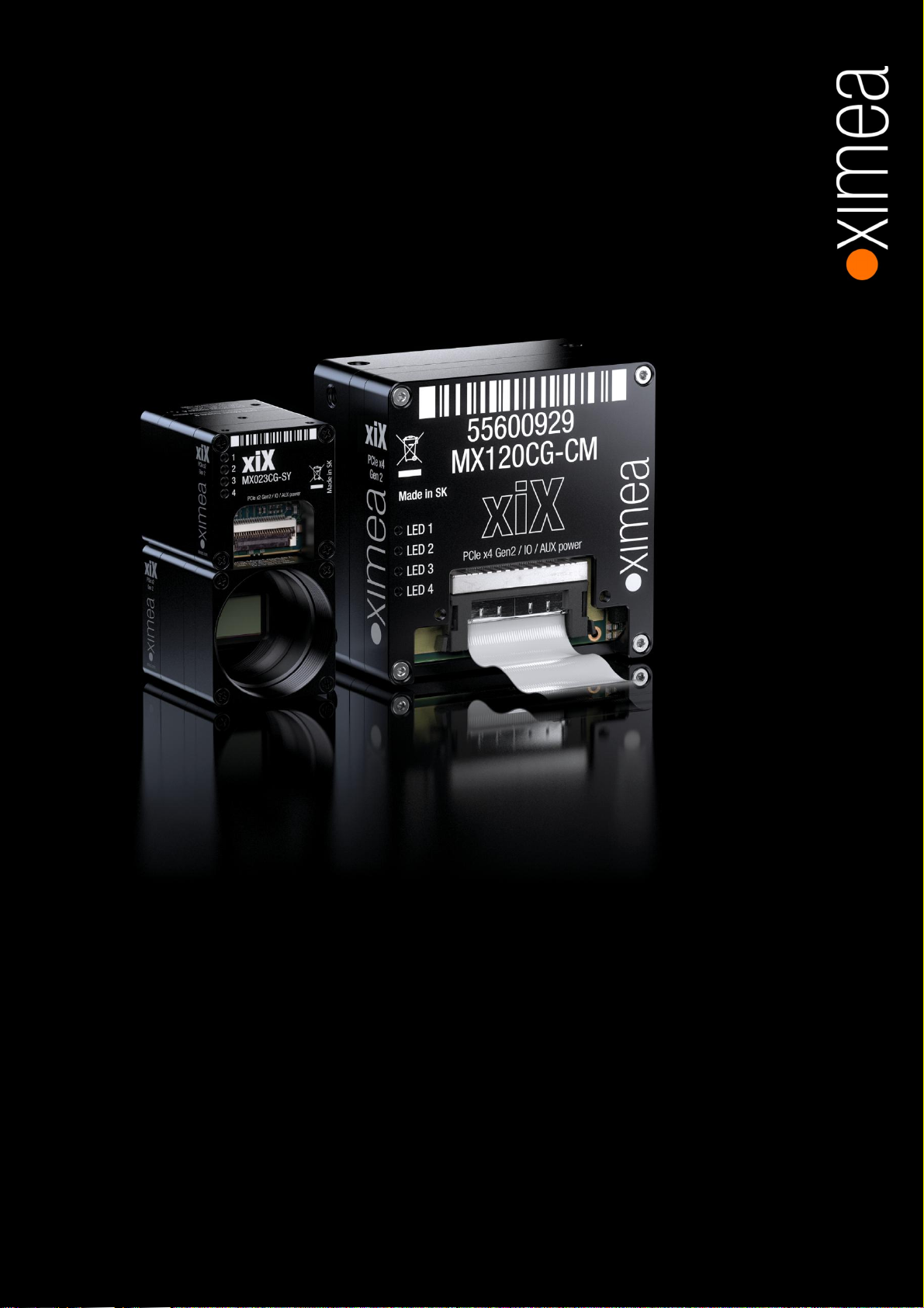
The main point behind the xiX family is a flat all-in-one cable with fast data interface, power and trig gering signals. This is ideal
for embedded and high-density applications. All standard co nnectors - like iPass, USB, Type-C - are much bigger than that and
require 2 cables for data and power/IO.
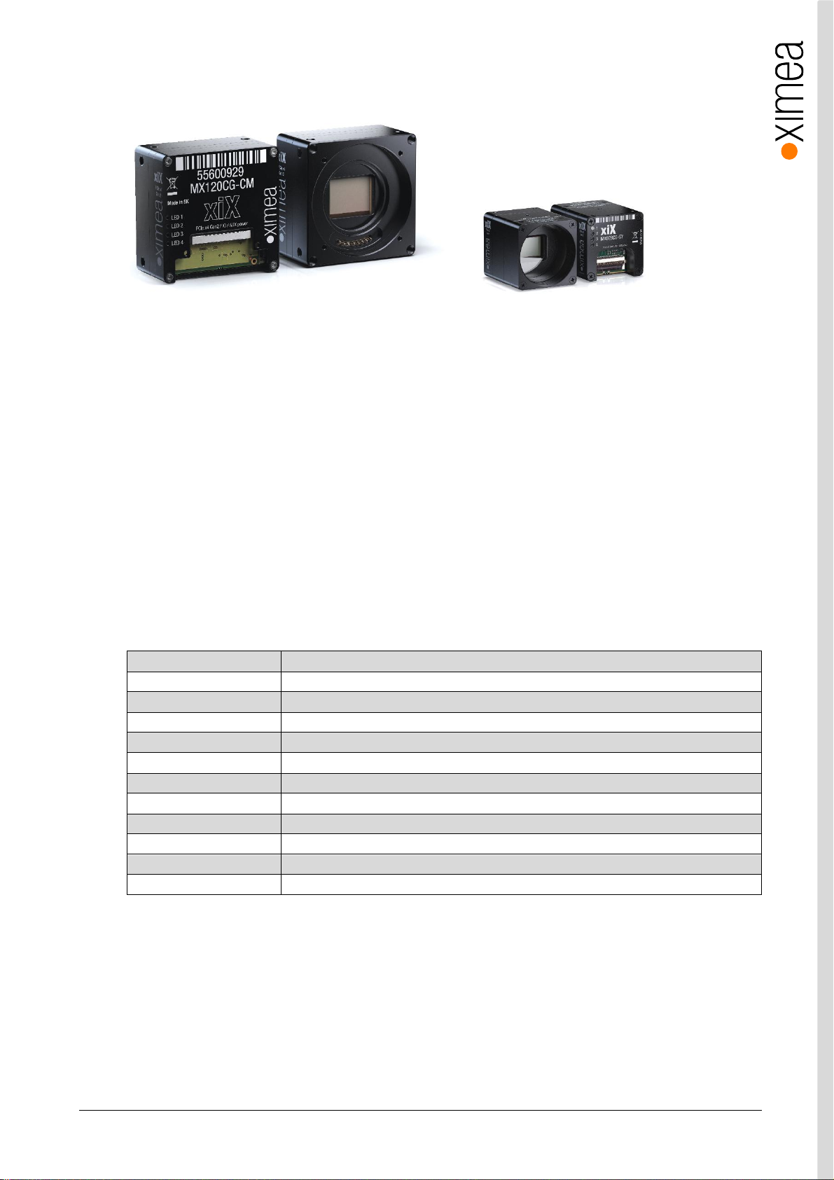
The xiX camera line comes with two form factors. Small (1inch square) with smaller sensors and interface PCIe x2 Gen2
(10Gbits /s ) and C/CS lens mount. Large (60x60mm) with interface PCIe x4 Gen2 (20Gbit/s) and active Canon EF-mount.
2.2. Advantages
Industry standard interface PCI express
Small Perfect size and customization options for Em bedded vision system applications
Powerful 20Gb/s interface using standard PCI express hardware (X4G2 models)
Fast High spe ed, high frame rate: >218fps at 3.1Mpix and 133fps at 12Mpix resolut ions
Robust Full meta l ‘s emi-housed’
Lightwei ght Facilitates increased performance of ro botic arms and gimbals
Connectivity Programmable opto-is olated I/O, and non-isolated digital input and output. 4 status LEDs
Compatibility Support for Windows, Linux and MacOS, various Image Processi ng Libraries
Software interfaces GenICa m / GenTL and highly optimized xiAPI SDK
Economical Excellent value and price, low TCO and fast ROI
Low latency Computer CPU not involved in data transfer, latency from camera t o memory is low
Optimized transfer GPU-direc t (Linux only) ideal for setupd using GPU for image proces sing
table 2-1, advantag es
is an ultra-compact PCI express industrial ca mera family with outstanding features:
xiX - Technical Manual Ve rsio n 1.3 11

2.3. PCI Express Vision Camera Applications
• Automation
• Ultra-fast 3D scanning
• Miniature and fast robotic arms
• Mobile devices
• In-situ optical inspection camera
• Material and life science microscopy
• Ophthalmology and retinal imaging
• Broadcasting
• Fast process capture, e.g. golf club swings
• Intelli gent Transportations Systems (ITS) and traffic monitoring
• VR and AR
• Cinematography
• Sports
• Unmanned vehicles
• UAV / Drones etc.
2.4. Common features
Sensor Technology CMOS, Global shutter
Acquisition Modes Continu ous, software and hardware tri gger, fps limiting, triggered exposure and burst
Partial Image Readout ROI, Skip ping and Binning modes supported (m odel specific)
Image data formats 8, 10 or 12 bit RAW pixel data
Color image proces sing Host based de-bayering, sharpening, Gamma, color matrix, true color CMS
Hot/blemish pixels correction On camera storage of up to 5000 pixel coordinates, host assisted correction
Auto adjustments Auto white balance, auto gain, auto exposure
Flat field corrections Host assisted pixel level shading and lens correctio ns
Image Data and Control Inte rface Ribbon cable and breakout board options to iPass e xternal PCIe connector
General Purpose I/O X2G2 models - 1x opto-isolated input, 1x opto-isolate d output, and 2 non-isolated
bidirectional I/O, 4X user configurable LEDs
X4G2 models - 2x opt o-isolated input, 2x opto-isolated output, and 4 non-isolated
bidirectional I/O, 4X user configurable LEDs
Synchronization Hardwa re trigger input, sof tware trigger, exposure strobe output, busy output
Housing and lens mount Standa rd C-mount convertible to CS mount, an d Ca non EF mount
Power requirem ents Externa l power supply required of 12-24V DC
Environment Operating 0°C to 50°C on housing, RH 80% non-condensing, -30°C to 60°C stor age
Operating systems Windows 10 (x86 and x64), Windows 7 (x86 and x64), Linux Ubuntu, MacOS 10.8
Software support xiAPI SDK, adapters and drivers for vario us image processing packages
Firmware updat es Field firmware updatable
table 2-2, common features
xiX - Technical Manual Ve rsio n 1.3 12
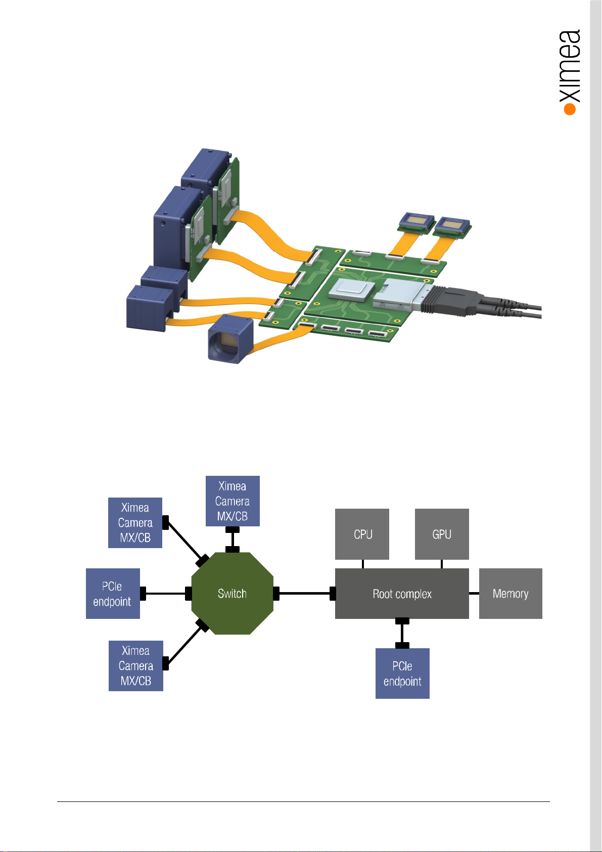
2.5. What is xSWITCH
Utilizing PCIe as a camera interface offers unique camera aggregation options, at extremely high bandwidths: multiple cameras
can be efficient ly connected and their respective data streams bundled into a single copper or fiber optic cable connection to a
host computer, writing directly to memory (DMA) at 64 Gbit/s. Flat-flex cables between the cameras and the xSWITCH allow the
most compact integration in tight spaces.
figure 2-1, Example of aggre gation of many camera in to one cable
PCIe allows multi camera assembly in to one cable stream with other end connecte d to e xpa nsion slot in host computer. It is
possible to chain several PCIe switches to create optimal infrastructure. Together with the cameras it is also possible to populate
PCIe switch downstream ports with other controllers, like USB 3.0, UART, etc.
figure 2-2, PCI Express Topology
xiX - Technical Manual Ve rsio n 1.3 13

HIGHLIGH TS
• Maximum compactness: smallest form factor cameras and mini connectors allow closest sensor-to-sensor proximity
• Aggregation into one high bandwidth upstream ( up to 64Gbit/s)
• Full utilization of PCIe architecture with point-to-point c onnection and direct memory access
• Use of standard components allows simple assembly for the creation of a custom platform
• No need for external or ad ditional expansion backplanes
• Multiple example types of xSWITCH board are already designed
• Shape of the board can be can be tailore d precisely to application requirements
• Benefit from XIMEA´s unique experience and expertise in the field of PCIe
MIX AND MATCH
• Connect multiple va rious camera models and types of cameras to a single computer
• Select from wide range of sensor resolutions and frame rates
• Combine housed and board level camera types
• Choice of different number of PCIe lanes and PCIe standards (2, 4, 8 lanes / Gen2 or Gen3)
• Choice of various connectors: flat-flex option, board to board or iPass
• Choose between flat-flex connectors with vertical or horizo ntal orientation
• Bridge small or large distances of >100 m by selecting copper cable or optical fiber cable
xiX - Technical Manual Ve rsio n 1.3 14
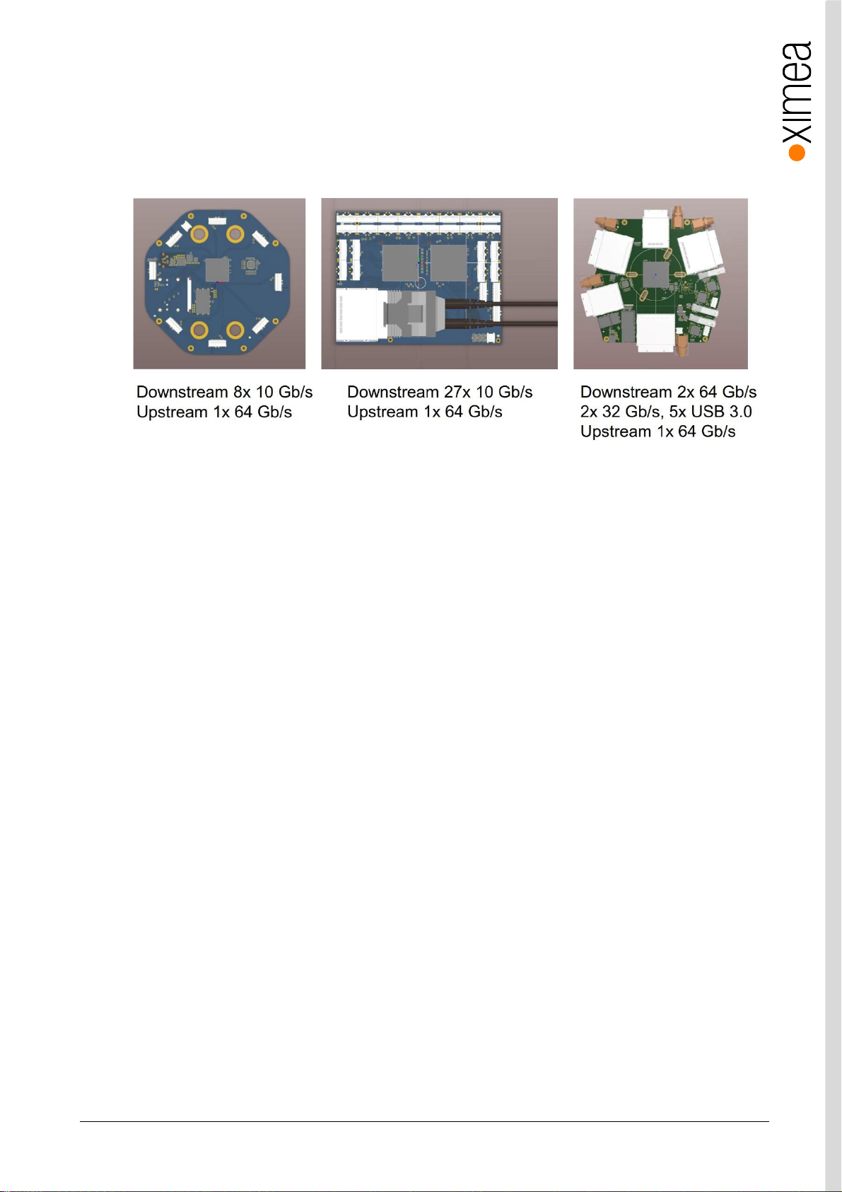
2.5.1. xSWITCH examples
By offering xSWITCH, XIMEA provides a PCB design where qu antity, type, location and orientatio n of PCIe connectors can be
varied to optimize the building of multi-camera systems. Multiple variations of these PCB designs already exist based on the
concept of empowering rapid customization of the final assembly and thus enabling most daring of custome r applications.
For more information please contact our sales: info@ximea.com
figure 2-3, Variations of Switches for Embedded vision systems
xiX - Technical Manual Ve rsio n 1.3 15

2.6. Model Nomenclature
Part number convention for the different models:
MXxxxyG-zz-XaGb [-OPT]
MX xiX family name
xxx: Resol ution in 0.1 MPixel . E.g . 2.3 MPixel Resolution: xxx = 023
y: y=C: color model
y=M: black & white model
y=R: black & white, Infrared-extended model
G: Global shutter (all xiX cameras are global shutter)
zz: Vendor of the sensor
zz = SY: Sony, CM: AMS/CMOSIS
[-OPT]: Options
OPT = FL: flexline variant, co nnector parallel to board, semi-housed
OPT = FV: flexline variant, connector vertical to board, sem i-housed
XaGb:
a = Number of PCIe lanes used, currently 2 or 4 lanes (b=2 or 4) for xiX cameras
b = PCIe generation, currently at Gen 2 (a=2) for the xiX cameras
xiX - Technical Manual Ve rsio n 1.3 16
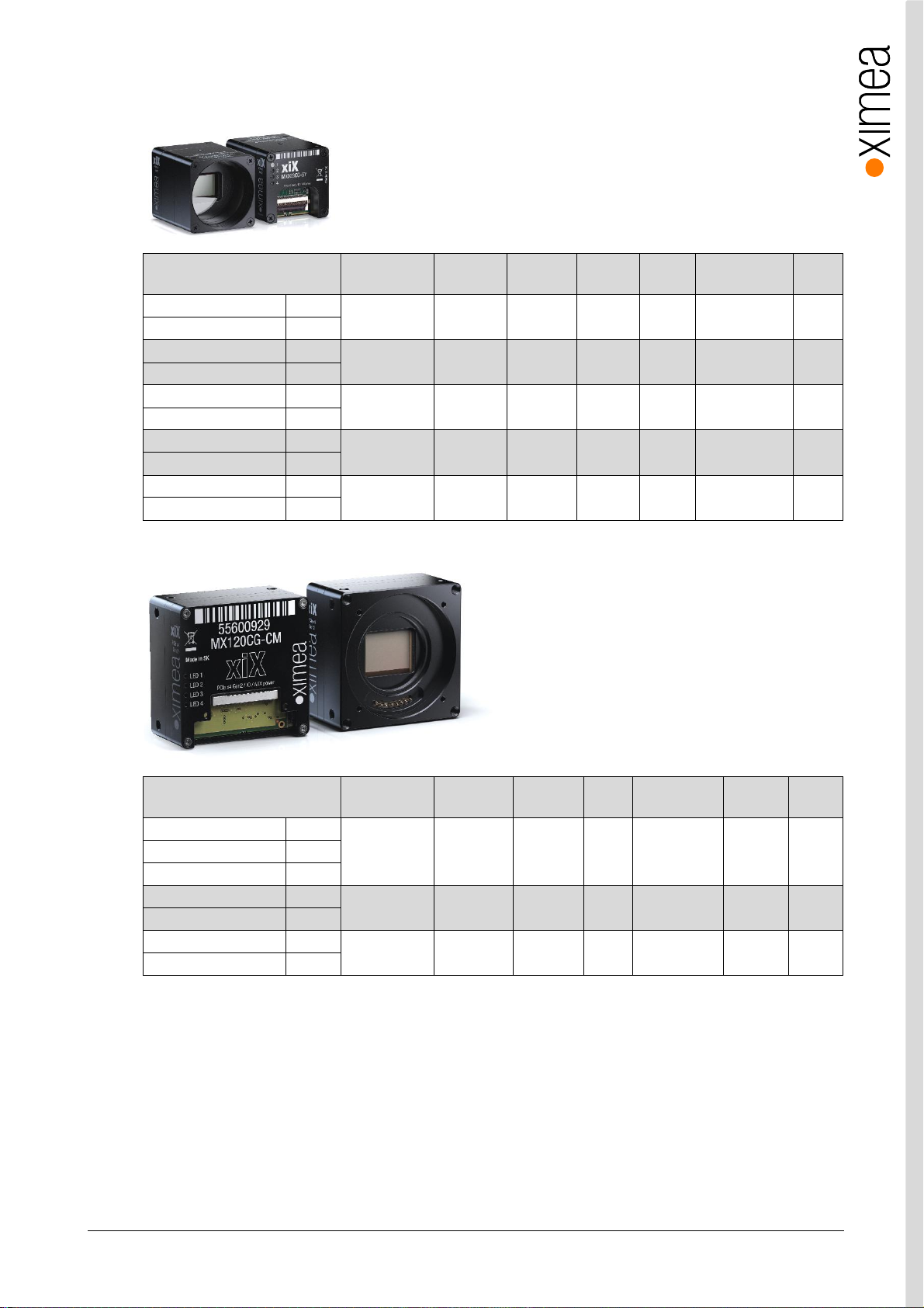
2.7. Models Overview, sensor and models
1
Model
MX023MG-SY-X2G2 b/w
MX023CG-SY-X2G2 Color
MX031MG-SY-X2G2 b/w
MX031CG-SY-X2G2 Color
MX050MG-SY-X2G2 b/w
MX050CG-SY-X2G2 Color
MX089MG-SY-X2G2 b/w
MX089CG-SY-X2G2 Color
MX124MG-SY-X2G2 b/w
MX124CG-SY-X2G2 Color
table 2-3, X2G2 models overview
Resolution Pixel size ADC [bit] DR
Optical
size
Sensor size
[mm]
FPS
1936 x 1216 5.86 µm 10/12 71.7 dB 1/1.2” 11.34x7.13 166
2064 x 1544 3.45 µm 8/10/12 70.8 dB 1/1.8” 7.23x5.33 218
2464 x 2056 3.45 µm 8/10/12 70.8 dB 2/3” 8.5x7.1 165
4112 x 2176 3.45 µm 8/10/12 70.5 dB 1” 14.19x7.51 95
4112 x 3008 3.45 µm 8/10/12 70.5 dB 1.1” 14.19x10.38 69
2
1
Model
MX120MG-CM-X4G2 b/w
MX120CG-CM-X4G2 Color
MX120RG-CM-X4G2 NIR
MX200MG-CM-X4G2 b/w
MX200CG-CM-X4G2 Color
MX200MG-CM-X4G2 b/w
MX200CG-CM-X4G2 Color
table 2-4, X4G2 models overview
Note: 1) In the model nam e please add
-FL for flat-flex cable connecting f rom t he bottom of the camera
-FV for flat-flex cable connecting perpendicular to the sensor
2) Full resolution, 8-bit RAW
Resolution Pixel size ADC [bit] DR
Sensor size
[mm]
Sensor
diagonal
FPS
4096 x 3072 5.5µm 8/10/12 60dB 22.53x16.9 28mm 133
5120 x 3840 6.4µm 12 66dB 32.76x24.58 41mm 32
7902 x 6004 4.6µm 12 64dB 36.35x27.62 45.6mm 30
2
xiX - Technical Manual Ve rsio n 1.3 17
2.8. Accessories
The following accessories are available:
Item P/N Description
CBL-MX-X2G2-0M07 0.07m flat ribbon cable for PCIe Gen 2 x2 cable
CBL-MX-X2G2-0M10 0.1m flat ribbon cable for PCIe Gen 2 x2 cable
CBL-MX-X2G2-0M25 0.25m flat ribbon cable for PCIe Gen 2 x2 cable
CBL-MX-X2G2-0M50 0.5m flat ribbon cable for PCIe Gen 2 x2 cable
CBL-MX-X4G2-0M10 0.1m flat ribbon cable for PCIe Gen 2 x4 cable
CBL-MX-X4G2-0M25 0.25m flat ribbon cable for PCIe Gen 2 x4 cable
CBL-MX-X4G2-0M50 0.5m flat ribbon cable for PCIe Gen 2 x4 cable
ADPT-MX-X2G2-IPASS-HOST-Fx
ADPT-MX-X2G2-IPASS-TARGET-Fx2 Breakout board from X2G2 flat ribbon cable to iPass X2G2
ADPT-MX-X2G2-M2-Fx
ADPT-MX-X2G2-M2SSD-Fx2 Breakout board from X2G2 flat ribbon cable to M.2 SSD socket
ADPT-MX-X2G2-MINI-PCIE-Fx
ADPT-MX-X2G2-PCIE-Fx
ADPT-MX-X2G2-X4G2 Breakout board from X2G2 flat ribbon to X4G2 ribbon (both directions)
ADPT-MX-X4G2-IPASS-HOST-Fx2 Breakout board from iPass X4G2 to X4G2 flat ribbon
ADPT-MX-X4G2-IPASS-TARGET-Fx2Breakout board from X4G2 flat ribbon cable to iPass X4G2
ADPT-MX-X4G2-M2-Fx
ADPT-MX-X4G2-MINI-PCIE-Fx
ADPT-MX-X4G2-PCIE-Fx
MECH-60MM-BRACKET-T xiB / xiX X4 G2 s eries tripod mounting bracket
MECH-60MM-EF-ADAPTER-KIT
MECH-MC-BRACKET-KIT xiX X2G2 / xiC series tripod mounting bracket
table 2-5, accessories
2
Breakout board from iPass X2G2 to X2G2 flat ribbon
2
2
2
2
2
2
Breakout board from M.2 to X2G2 ribbon cable
Breakout board from Mini P CIe to X2G2 flat ribbon
Breakout board from PC Ie to X2G2 flat ribbon
Breakout board from M.2 to X4G2 ribbon cable
Breakout board from Mini P CIe to X4G2 flat ribbon
Breakout board from PC Ie to X4G2 flat ribbon
1
xiB / xiT Canon EF-Mount Ada pte r
Notes: 1) This kit is sold separately, however it is possible to order assembling during prod uction. These assemblies are
sold separately. Additional assemblies purchased along with a camer a can be added to the order at time of
purchase for assembly with camera head. See table 2-6
2) Adapters are available in vertical (-FV) and horizontal orientation (-FL) of flat ribbon connector
Item P/N Description
A-MECH-60MM-EF-ADAPTER-KIT1Assembly Service for MECH-60MM-EF-ADAPTER-KIT
table 2-6, assembly options
Notes: 1) Available only for MX120 and MX200 models.
xiX - Technical Manual Ve rsio n 1.3 18
3. Hardware Specification
3.1. Power Supply
The xiX cameras are powered via flex cable from an external power supply 12-24V with power consumption up to 10W max
(without power needed for lens). Please read the c hapter3.8 xiX X2G2 Interface connector and 3.9 xiX X4G2 Interface connector
regarding camera pi nout. Breakout board can be used to power cam era see3.14 MX came ra adapters
3.2. General Specification
3.2.1. Environment
Description Symbol Value
Optimal ambient temperature operation
Ambient temperat ure ope ration
Ambient temperature for storage and transportation
Relative Humidity, non-con de nsing RH ≤ 80 %
table 3-1, environment
Housing temperat ure must not exceed +65°C. The following parameters are not guaranteed if th e camera is operated outside
the optimum range:
• Dark cur rent
• Dynamic Range
• Linearity
• Acquisition and read out noise
• S/N ratio, durab ilit y
Please refer to chapter:3.11 Heat Dissipation
T
opt
T
max
T
storage
+10 to +25 °C
0 to +50 °C
-30 to +60 °C
3.2.2. Firmware / Host driver / API features
Description Value
Interpolation methods SHT advanced
White balance coefficients r anges 0.0 to 3.9
Sharpness filter -400 to 400 %
Gamma 0.3 to 1.0
Full color correction matrix (3+1)x3 coefficients ranges -3.9 to 3.9
table 3-2, firmware / API features
More details on API/SDK features are available at XIMEA support pages: http://www.ximea.com/support
xiX - Technical Manual Ve rsio n 1.3 19
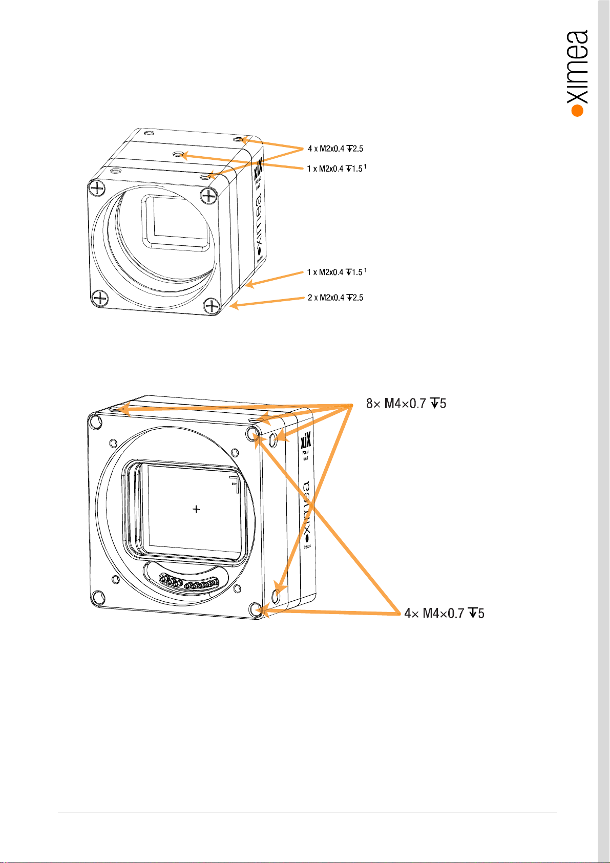
3.3. Mounting points
Cameras fe ature mounting threads enabli ng to be mounted on construction or via t ripod adapter to standard tripod.
MX X2G2
figure 3-1, MX X2G2 mounting points (note 1: models MX089xG and MX124xG do not have this mounting hole)
MX X4G2
figure 3-2, MX X4G2 mounting points
xiX - Technical Manual Ve rsio n 1.3 20
3.4. Lens Mount
The xiX cameras have a couple lens mounts available. The smaller cameras (X2G2) have a C-mount, and the larger ones can
optional ly be included with a Ca non EF mount.
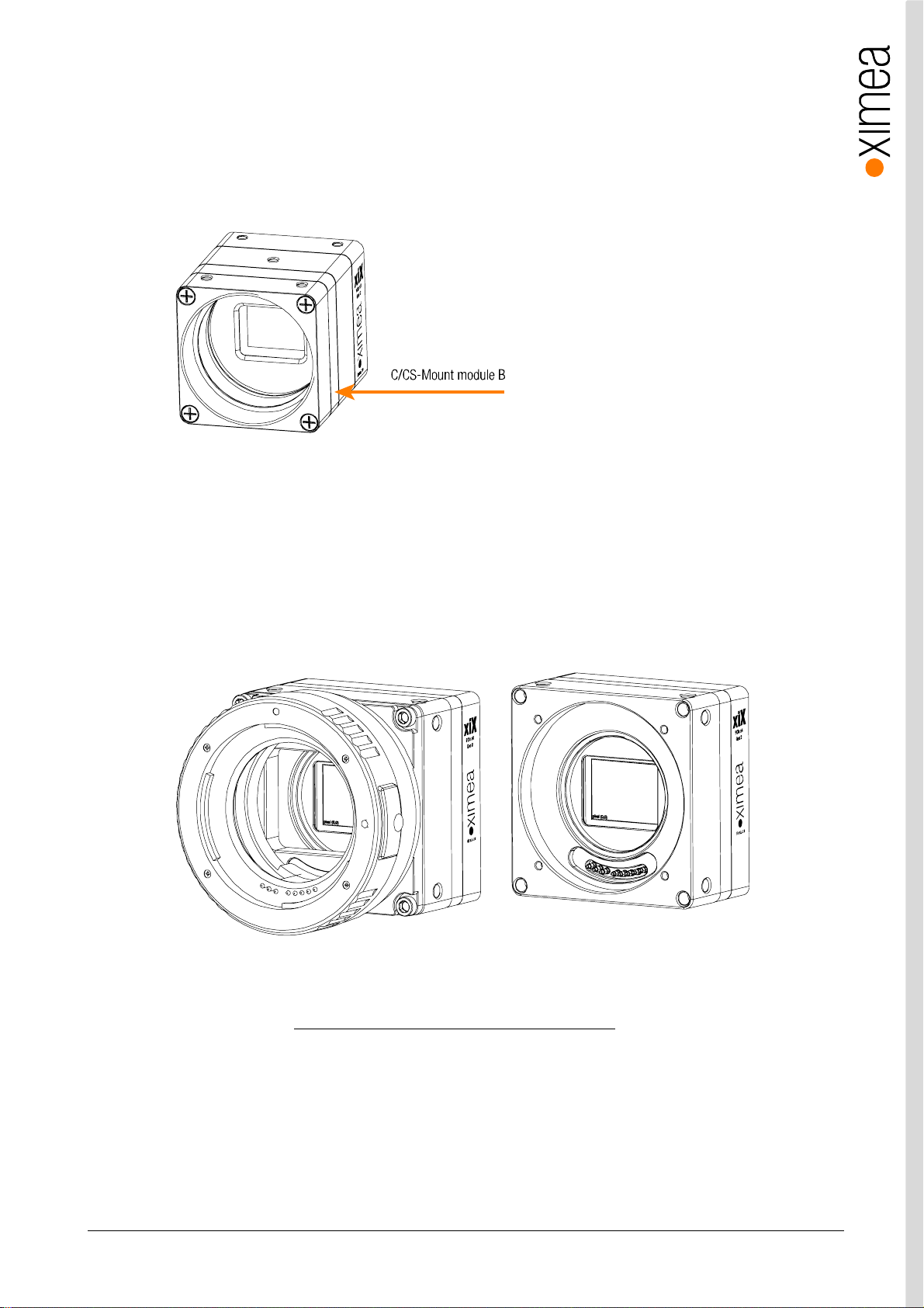
figure 3-3, MX X2G2 position C/CS-Mount module B
The smaller cameras are delivered with C-mount back focal length. By removing the “C /CS-Mount module B” (see the figure
above) the camera can be rebuilt to CS-mount compatibility. Effecti vely reducing the back focal distance and overall length of
camera by 5mm. The required M2x8mm special screws are part of the camera delivery. The length of the lens thread is 6.5
mm.
Note: The distance between the threaded flange and the surface of the filter glass is 11.9 mm in case of C-Mount and 6.9 mm
in case of CS -Mount. To avoid damaging of the filter glass, nothing may extend deepe r into the housing.
figure 3-4, MX X4G2 camera with /without the optional EF-Mount Adapter
The cameras are optionally delive red with or without outer EF-Mount Adapter.
For more information refer to 3.16 xiX X4G2 Lens adapter – MECH-60MM-EF-ADAPTER
Note: The distance between the outer EF-Mou nt Adapter and the active sensor surface is 44 mm and when no EF-Mount
Adapter is included it is 13.4 mm.
xiX - Technical Manual Ve rsio n 1.3 21
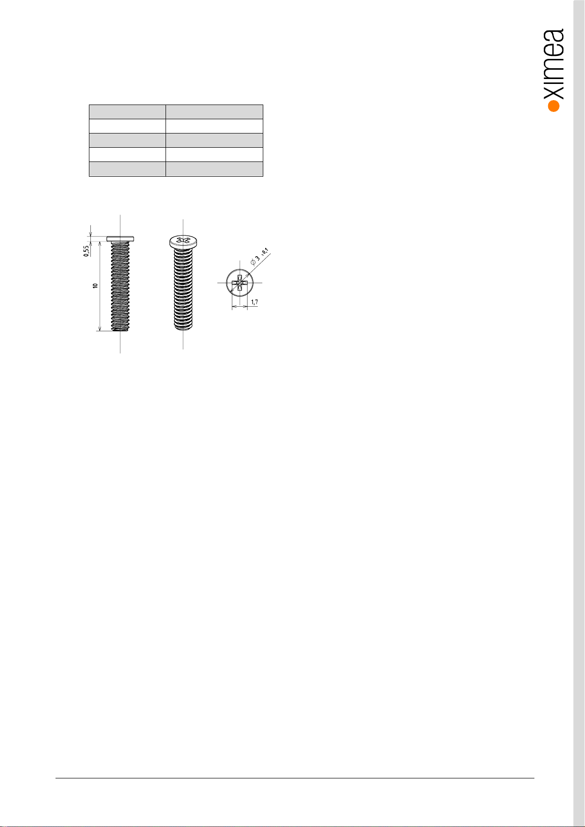
3.4.1. Screws
All mounting screws for MX X2G2 are customized M2 screws with different lengths.
Technical details:
Material Steel
Surface Black zinc
Thread M2
Driver PH 00
Avail. Lengths 3mm – 24 mm
Drawings, e.g. w ith 10mm length:
table 3-3, custom screws, technical details
figure 3-5, xiX mounting screws
Note: Never excee d a maximum torque of 0.3Nm when fastening the M2 mo unting screws.
As mounting screws for MX X4G2 Sta ndard M4 screws can be used.
xiX - Technical Manual Ve rsio n 1.3 22
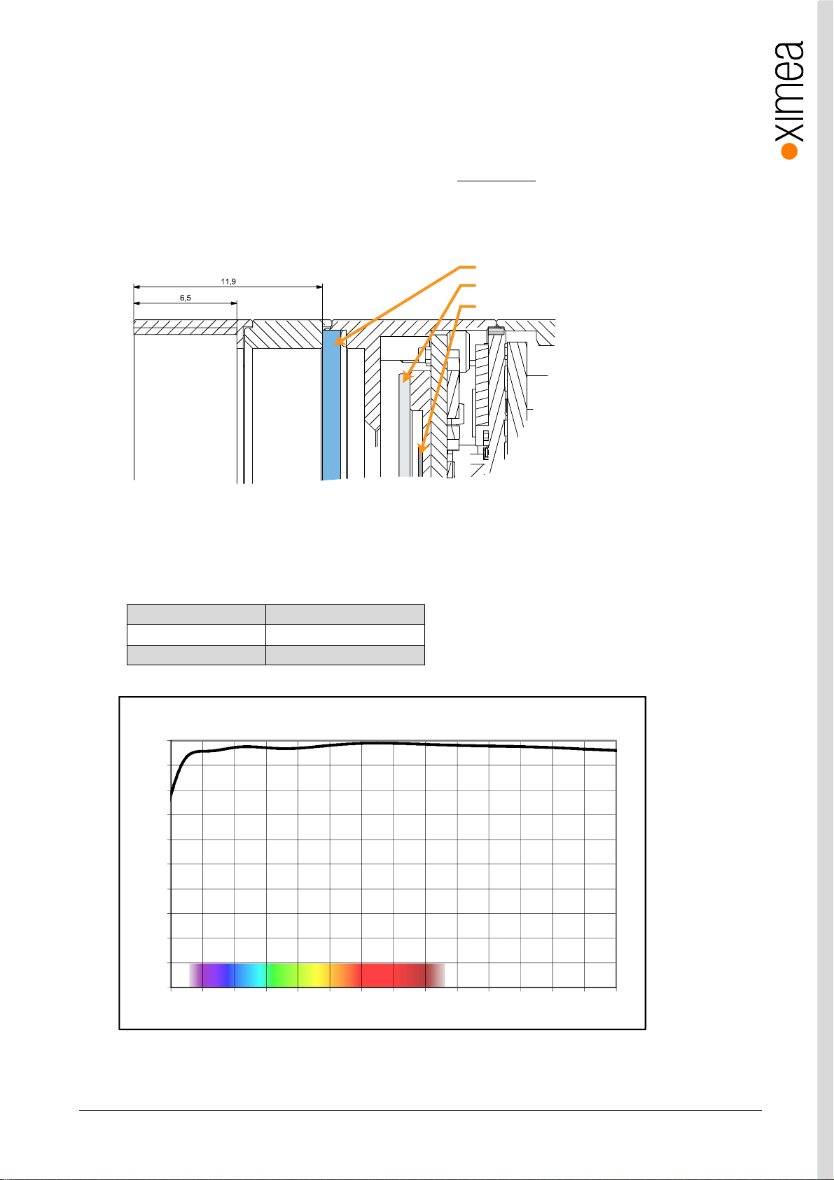
3.5. Optical path
3.5.1. Filter glasses
A filter glass is part of the optical path of the camera. This glass is placed on a layer of silicone, to keep dust out of the camera,
but not glued. The conversion of C-mount to CS-mount (see section 3.4 Lens Mount) must be carried out carefully. Operating the
camera without a lens mo unt is not intende d and can lead to dropping out of the filter glass a nd the entry of dust. . Do not use
compressed air to clean the camera as this could push dust int o the camera. Distance from the flange to sensor is designed so
the optical distance is 17.526mm – 0.2mm.
filter glass
sensor cover glass
sensor die
figure 3-6, Optical path section MX X2G2
MX X4G2 does not feature filterglass in the optical path
3.5.2. Monochrome and near infrared extended camera models (MX X2G2 models only)
Used filter brand BK7 AR2x
Thickness 1.0±0.1 mm
Coating Anti-reflex both sides
table 3-4, monochrome camera - filter glas s parameter
BK7 AR2x - Transmission Curve
100
90
80
70
60
50
40
30
Transmittance (%)
20
10
0
350 400 450 500 550 600 650 700 750 800 850 900 950 1000 1050
Wavelength (nm)
figure 3-7, monochrome camera - filter glass transmission curve
xiX - Technical Manual Ve rsio n 1.3 23
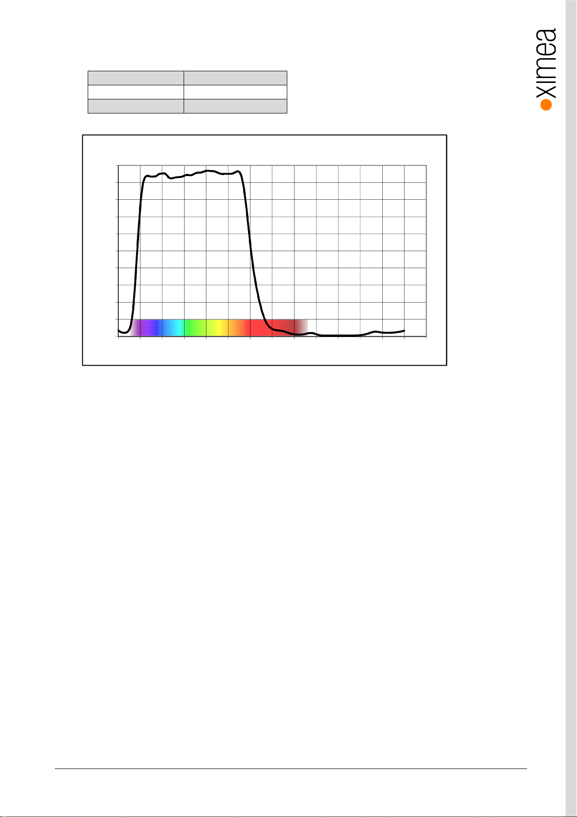
3.5.3. Color camera models (MX X2G2 models only)
Used filter brand ICR650
Thickness 1.0±0.1 mm
Coating NA
table 3-5, color camera - filte r glass parameter
ICR650 - Transmission Curve
100
90
80
70
60
50
40
30
Transmittance (%)
20
10
0
350 400 450 500 550 600 650 700 750 800 850 900 950 1000 1050
Wavelength (nm)
figure 3-8, color camera - filter glass transmission curve
xiX - Technical Manual Ve rsio n 1.3 24

3.6. Model Specific Characteristics
3.6.1. MX023xG-SY-X2G2-Fx
3.6.1.1. Sensor and camera p arameters
xiX model MX023CG-SY-X2G2-Fx MX023MG-SY-X2G2-Fx
Sensor parameter
Model name IMX174LQJ-C IMX174LLJ-C
Color filter RGB Bayer mosaic None
Type Global shutter, o verlap mode
Pixel Resolution (H × V) [pixel] 1936 x 1216
Active area size (H × V) [mm] 11.314 x 7.12
Sensor dia go nal [mm] 13.39
Optical format [inch] 1/1.2
Pixel Size (H × V) [µm] 5.86 x 5.86
ADC resolution [bit] 10, 12
FWC [ke-] 30.5
Dynamic range [dB] 71.7
SNR Max [dB] 45
Conversion gain [e-/LSB12] 8.1
Dark noise [e-] 7.36
Dark current [e-/s] 3
DSNU [e-] 1.1
PRNU [%] 0.4
Linearity [%] 0.5
Camera parameters
Digitization [bit] 10, 12
Supported bit resolutions [bit/pixel] 8, 10, 12
Exposu re time (EXP) 19µs to 30sec, in steps of 4.96µs
Variable Gain Rang e (VGA) [dB] 0-24
Refresh rate (MRR) [fps] 166
Power consumption
typical [W] 2.87
Maximum [W] 2.95
Dimensions/Mass
height [mm] 26.4
width [mm] 26.4
depth (-FL/-FV) [mm] 30.9 (with C/CS Mount module B)
mass (-FL/-FV) [g] 30 (with C/CS Mount module B)
table 3-6, MX023xG-SY-X2G2-Fx, se nsor and c amera parameters
1
25.9 (without C/ CS Mount module B)
25.8 (without C/ CS Mount module B)
Notes:
1) Defined for maximal bandwidth. Minimal Exposure and exposure step (Line Period) could be ca lculated in:
Camera performance calculator:
https://www.ximea.com/support/attachments/download/7828/Camera_Performance_Calculator.xlsm
xiX - Technical Manual Ve rsio n 1.3 25
Color model Mono mode Binning/skipping pixels fps Bit/px
Yes Yes 1x1 1936 x 1216 166 8
Yes Yes 1x1 1936 x 1216 166 10
Yes Yes 1x1 1936 x 1216 129 12
table 3-7, MX023xG-SY-X2G2-Fx, su pported standard readout modes
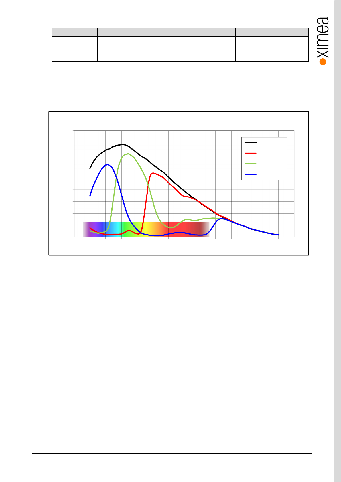
3.6.1.2. Quantum efficiency curves [%]
IMX174 - Spectral Response
90%
80%
70%
60%
50%
40%
30%
20%
Quantum Efficiency (%)
10%
0%
350 400 450 500 550 600 650 700 750 800 850 900 950 1000 1050
Monochrome
Red Bayer
Green Bayer
Blue Bayer
Wavelength (nm)
figure 3-9, IMX174-mono, quantum efficiency curve, ©SONY
xiX - Technical Manual Ve rsio n 1.3 26
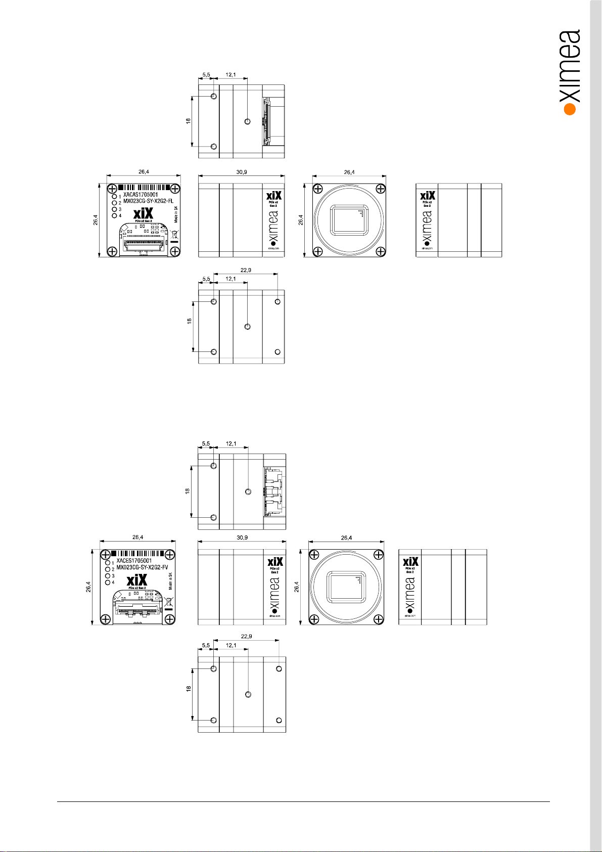
3.6.1.3. Drawings MX023xG-SY-X2G2-FL (C-mount [with C/CS mount module B])
figure 3-10, dimensiona l drawing MX023x G-SY-X2G2-FL, C-Mount housing
3.6.1.4. Drawings MX023xG-SY-X2G2-FV (C-mount [with C/CS mount module B])
figure 3-11, dimensional dra wing MX023xG-S Y-X 2G2 -FV, C-Mount hous ing
xiX - Technical Manual Ve rsio n 1.3 27

3.6.1.5. Referenced docume nts
Sony Datasheet IMX174LQJ-C_E_TechnicalDatasheet_REv0.3 (01/06/14)
Sony Datasheet IMX174LLJ-C_E_data_sheet_E14315 (01/06/14)
3.6.1.6. Sensor features
feature Note
Binni ng No
Skip pi ng Not supported
ROI Vertical cropping results in increased read speed, horizontal reduces data tr ansfer
HW Trigger
HDR Not available
table 3-8, sensor features available
Trigger without o verlap usable (see 4. 3.2 Triggered Ac quisition)
xiX - Technical Manual Ve rsio n 1.3 28

3.6.2. MX031xG-SY-X2G2-Fx
3.6.2.1. Sensor and camera p arameters
xiX model MX031CG-SY-X2G2-Fx MX031MG-SY-X2G2-Fx
Sensor parameter
Model name IMX252LQR-C IMX252LLR-C
Color filter RGB Bayer mosaic None
Type Global shutter, o verlap mode
Pixel Resolution (H × V) [pixel] 2064 x 1544
Active area size (H × V) [mm] 7.12 x 5.33
Sensor dia go nal [mm] 8.89
Optical format [inch] 1/1.8
Pixel Size (H × V) [µm] 3.45 × 3.45
ADC resolution [bit] 8, 10, 12
FWC [ke-] 9.9
Dynamic range [dB] 70.9
SNR Max [dB] 40.3
Conversion gain [e-/LSB12] 2.67
Dark noise [e-] 2.32
Dark current [e-/s] 2.1
DSNU [e-] 0.7
PRNU [%] 0.65
Linearity [%] 0.5
Camera parameters
Digitization [bit] 83, 10, 12
Supported bit resolutions [bit/pixel] 8, 10, 12
Exposu re time (EXP) 1µs2 to 30sec, in steps of 5.29µs
Variable Gain Rang e (VGA) [dB] 0-24
Refresh rate (MRR) [fps] 218
Power consumption
typical [W] 3.64
Maximum [W] 3.72
Dimensions/Mass
height [mm] 26.4
width [mm] 26.4
depth [mm] 30.8 (with C/CS Mount module B)
mass [g] 30 (with C/CS Mount module B)
table 3-9, MC031xG-SY-X2G2-Fx, sensor and camera parameters
1
25.8 (without C/ CS Mount module B)
25.8 (without C/ CS Mount module B)
Notes:
1) Defined for maximal bandwidth. Minimal Exposure and exposure step (Line Period) could be ca lculated in:
Camera performance calculator:
https://www.ximea.com/support/attachments/download/7828/Camera_Performance_Calculator.xlsm
2) From 1 µs to 14 µs t he step is 1µs and the sensor is operating in special mode. This exposure times are not
achieva ble for exposure co ntrolled by trigger pulse length.
3) Saturation level in 8bit digitization is only ¼ of 10bit and 12bit mode (see 4.2.5 Digitization bit depth)
xiX - Technical Manual Ve rsio n 1.3 29
Color model Mono model Binning/skipping (H X V) pixels fps Bit/px
Yes Yes 1x1 / 1x1 2064 x 1544 218 8
Yes Yes 1x1 / 1x1 2064 x 1544 193 10
Yes Yes 1x1 / 1x1 2064 x 1544 119 12
Yes Yes 1x1 / 1x2 2064 x 772 426 8
Yes Yes 1x1 / 2x1 1032 x 1544 218 8
Yes Yes 1x1 / 2x2 1032 x 772 426 8
No Yes 1x2 / 1x1 2064 x 772 426 8
No Yes 1x2 / 2x1 1032 x 772 426 8
Yes Yes 1x1 / 2x2 1032 x 772 378 10
Yes Yes 1x1 / 2x2 1032 x 772 233 12
table 3-10, MC031 xG-S Y, supported standard readout mod es
Notes:
1) Defined for ban dwidth 900MB/s.Camera performance calculator:
https://www.ximea.com/support/attachments/download/7828/Camera_Performance_Calculator.xlsm
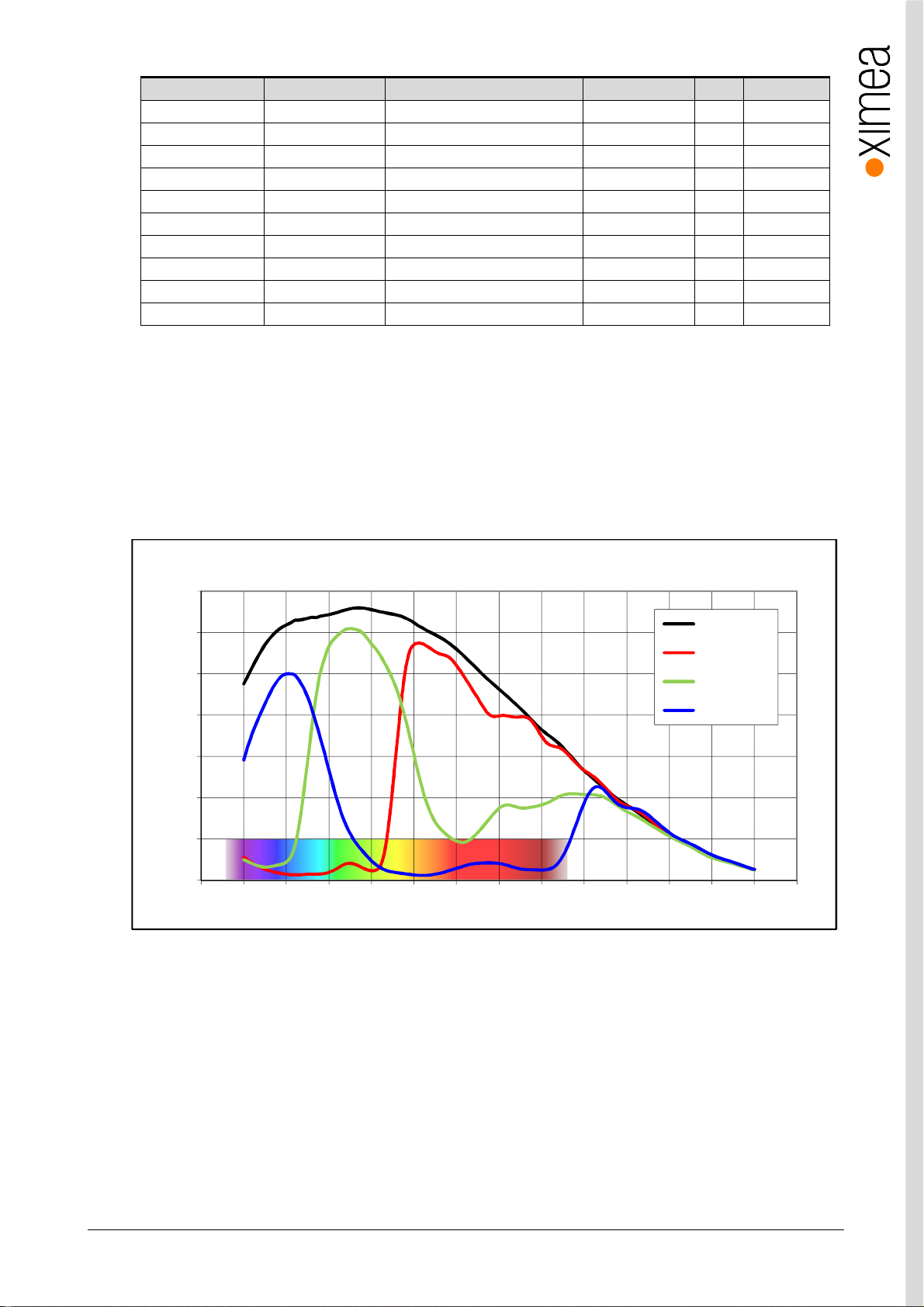
3.6.2.2. Qua ntum efficiency curves [%]
IMX252- Spectral Response
70%
60%
50%
40%
30%
20%
Quantum Efficiency (%)
10%
0%
350 400 450 500 550 600 650 700 750 800 850 900 950 1000 1050
Wavelength (nm)
figure 3-12, IMX252-mono and color, quantum efficiency curves, ©SONY
Monochro me
Red Bayer
Green Bayer
Blue Bayer
xiX - Technical Manual Ve rsio n 1.3 30

3.6.2.3. Drawings MX031xG-SY-X2G2-FL (C-mount [with C/CS mount module B])
figure 3-13, dimensiona l drawing MX031x G-SY-X2G2-FL, C-Mount housing
3.6.2.4. Drawings MX031xG-SY-X2G2-FV (C-mount [with C/CS mount module B])
figure 3-14, dimensional dra wing MX031xG-S Y-X 2G2 -FV, C-mount hous ing
xiX - Technical Manual Ve rsio n 1.3 31

3.6.2.5. Ref eren ced doc ume nts
Sony Datasheet IMX252LLR-C_Data_Sheet(E)_E15903 (03/09 /15)
Sony Datasheet IMX252LQR-C_Data_Sheet(E)_E15911 (11/09/15)
3.6.2.6. Se nsor feat ures
feature Note
Binni ng Yes, 1x2 ( H x V) binning supported on monochrome only.
Skipping Yes, 2x2
ROI Vertical cropping results in increased read speed, horizontal reduces data tr ansfer
HW Trigger
HDR Current ly no t s upported
table 3-11, sensor features available
Trigger without o verlap usable (see 4. 3.2 Triggered Ac quisition)
xiX - Technical Manual Ve rsio n 1.3 32

3.6.3. MX050xG-SY-X2G2-Fx
3.6.3.1. Se nsor an d camera parameters
xiX model MX050CG-SY-X2G2-Fx MX050MG-SY-X2G2-Fx
Sensor parameter
Model name IMX250LQR-C IMX250LLR-C
Color filter RGB Bayer mosaic None
Type Global shutter, o verlap mode
Pixel Resolution (H × V) [pixel] 2464 x 2056
Active area size (H × V) [mm] 8.5 x 7.09
Sensor dia go nal [mm] 11.1
Optical format [inch] 2/3
Pixel Size (H × V) [µm] 3.45 x 3.45
ADC resolution [bit] 8, 10, 12
FWC [ke-] 9.8
Dynamic range [dB] 70.8
SNR Max [dB] 40.3
Conversion gain [e-/LSB12] 2.66
Dark noise [e-] 2.32
Dark current [e-/s] 3.9
DSNU [e-] 0.75
PRNU [%] 0.61
Linearity [%] 0.5
Camera parameters
Digitization [bit] 83, 10, 12
Supported bit resolutions [bit/pixel] 8, 10, 12
Exposu re time (EXP) 1µs2 to 30sec, in steps of 6.32µs
Variable Gain Rang e (VGA) [dB] 0-24
Refresh rate (MRR) [fps] 165
Power consumption
typical [W] 3.64
Maximum [W] 3.72
Dimensions/Mass
height [mm] 26.4
width [mm] 26.4
depth [mm] 30.8 (with C/CS Mount module B)
mass [g] 30 (with C/CS Mount module B)
table 3-12, MX050xG-SY-X2G2-Fx, sensor and c amera parameters
1
25.8 (without C/ CS Mount module B)
25.8 (without C/ CS Mount module B)
Notes:
1) Defined for maximal bandwidth. Minimal Exposure and exposure step (Line Period) could be ca lculated in:
Camera performance calculator:
https://www.ximea.com/support/attachments/download/7828/Camera_Performance_Calculator.xlsm
2) From 1 µs to 14 µs t he step is 1µs and the sensor is operating in special mode. This exposure times are not
achieva ble for exposure co ntrolled by trigger pulse length.
3) Saturation level in 8bit digitization is only ¼ of 10bit and 12bit mode (see 4.2.5 Digitization bit depth)
xiX - Technical Manual Ve rsio n 1.3 33

Color model Mono mode Binning/skipping (H X V) pixels Fps
Yes Yes 1x1 / 1x1 2464 x 2056 165 8
Yes Yes 1x1 / 1x1 2464 x 2056 146 10
Yes Yes 1x1 / 1x1 2464 x 2056 90 12
Yes Yes 1x1 / 1x2 2464 x 1028 324 8
Yes Yes 1x1 / 2x1 1232 x 2056 164 8
Yes Yes 1x1 / 2x2 1232 x 1028 322 8
No Yes 1x2 / 1x1 2464 x 1028 324 8
No Yes 1x2 / 2x1 1232 x 1028 322 8
Yes Yes 1x1 / 2x2 1232 x 1028 270 10
Yes Yes 1x1 / 2x2 1232 x 1028 177 12
table 3-13, MX050xG-SY-X2G2-Fx, supported standard readout modes
Notes:
2) Defined for ban dwidth 900MB/s.Camera performance calculator:
https://www.ximea.com/support/attachments/download/7828/Camera_Performance_Calculator.xlsm
3.6.3.2. Qua ntum efficiency curves [%]
1)
Bit/px
IMX250- Spectral Response
70%
60%
50%
40%
30%
20%
Quantum Efficiency (%)
10%
0%
350 400 450 500 550 600 650 700 750 800 850 900 950 1000 1050
Wavelength (nm)
figure 3-15, IMX250 mono and color, quantum efficiency curves, ©SONY
Monochro me
Red Bayer
Green Bayer
Blue Bayer
xiX - Technical Manual Ve rsio n 1.3 34

3.6.3.3. Drawings MX050xG-SY-X2G2-FL (C-mount [with C/CS mount module B])
figure 3-16, dimensiona l drawing MX050x G-SY-X2G2-FL, C-Mount housing
3.6.3.4. Drawings MX050xG-SY-X2G2-FV (C-mount [with C/CS mount module B])
figure 3-17, dimensional dra wing MX050xG-S Y-X 2G2 -FV, C-Mount hous ing
xiX - Technical Manual Ve rsio n 1.3 35

3.6.3.5. Ref eren ced doc ume nts
Sony Datasheet IMX250LLR-C_Data_Sheet(E)_E15902 (02/09 /15)
Sony Datasheet IMX250LQR-C_Data_Sheet(E)_E15910 (10/09/15)
3.6.3.6. Se nsor feat ures
feature Note
Binni ng Yes, 1x2 ( H x V) binning supported on monochrome only.
Skipping Yes, 2x2
ROI Vertical cropping results in increased read speed, horizontal reduces data tr ansfer
HW Trigger
HDR Not available
table 3-14, sensor features available
Trigger without o verlap usable (see 4. 3.2 Triggered Ac quisition)
xiX - Technical Manual Ve rsio n 1.3 36

3.6.4. MX089xG-SY-X2G2-Fx
3.6.4.1. Se nsor an d camera parameters
xiX model MX089CG-SY-X2G2-Fx MX089MG-SY-X2G2-Fx
Sensor parameter
Model name IMX255LQR-C IMX255LLR-C
Color filter RGB Bayer mosaic None
Type Global shutter, o verlap mode
Pixel Resolution (H × V) [pixel] 4112 x 2176
Active area size (H × V) [mm] 14.2 x 7.5
Sensor dia go nal [mm] 16
Optical format [inch] 1”
Pixel Size (H × V) [µm] 3.45 x 3.45
ADC resolution [bit] 8, 10, 12
FWC [ke-] 9.8
Dynamic range [dB] 70.5
SNR Max [dB] 40.3
Conversion gain [e-/LSB12] 2.67
Dark noise [e-] 2.4
Dark current [e-/s] 3.9
DSNU [e-] 0.75
PRNU [%] 0.61
Linearity [%] 0.5
Camera parameters
Digitization [bit] 83, 10, 12
Supported bit resolutions [bit/pixel] 8, 10, 12
Exposu re time (EXP) 1µs2 to 30sec, in steps of 10.54µs
Variable Gain Rang e (VGA) [dB] 0-24
Refresh rate (MRR) [fps] 95
Power consumption
typical [W] 3.82
Maximum [W] 3.88
Dimensions/Mass
height [mm] 26.4
width [mm] 26.4
depth [mm] 30.9 (with C/CS Mount module B)
mass [g] 30 (with C/CS Mount module B)
table 3-15, MX089xG-SY-X2G2-Fx, sensor and c amera parameters
1
25.9 (without C/ CS Mount module B)
25.8 (without C/ CS Mount module B)
Notes:
1) Defined for maximal bandwidth. Minimal Exposure and exposure step (Line Period) could be ca lculated in:
Camera performance calculator:
https://www.ximea.com/support/attachments/download/7828/Camera_Performance_Calculator.xlsm
2) From 1 µs to 14 µs t he step is 1µs and the sensor is operating in special mode. This exposure times are not
achieva ble for exposure co ntrolled by trigger pulse length.
3) Saturation level in 8bit digitization is only ¼ of 10bit and 12bit mode (see 4.2.5 Digitization bit depth)
xiX - Technical Manual Ve rsio n 1.3 37

Color model Mono model Binnin g/skipping (H X V) pixels Fps
Yes Yes 1x1 / 1x1 4112 x 2176 95.4 8
Yes Yes 1x1 / 1x1 4112 x 2176 79.1 10
Yes Yes 1x1 / 1x1 4112 x 2176 64.9 12
Yes Yes 1x1 / 1x2 4112 x 1088 187.6 8
Yes Yes 1x1 / 2x1 2056 x 2176 95.2 8
Yes Yes 1x1 / 2x2 2056 x 1088 187 8
No Yes 1x2 / 1x1 4112 x 1088 172.8 8
No Yes 2x2 / 1x1 2056 x 1088 187 8
No Yes 2x2 / 1x1 2056 x 1088 177 10
No Yes 2x2 / 1x1 2056 x 1088 127.6 12
Yes Yes 1x1 / 2x2 2056 x 1088 177 10
Yes Yes 1x1 / 2x2 2056 x 1088 127.6 12
table 3-16, MX089xG-SY-X2G2-Fx, supported standard readout modes
Notes:
1) Defined for ban dwidth 900MB/s.Camera performance calculator:
https://www.ximea.com/support/attachments/download/7828/Camera_Performance_Calculator.xlsm
3.6.4.2. Qua ntum efficiency curves [%]
1)
Bit/px
IMX255- Spectral Response
70%
60%
50%
40%
30%
20%
Quantum Efficiency (%)
10%
0%
350 400 450 500 550 600 650 700 750 800 850 900 950 1000 1050
Wavelength (nm)
figure 3-18, IMX255 mono and color, quantum efficiency curve, ©SONY
Monochro me
Red Bayer
Green Bayer
Blue Bayer
xiX - Technical Manual Ve rsio n 1.3 38

3.6.4.3. Drawings MX089xG-SY-X2G2-FL (C-mount [with C/CS mount module B])
figure 3-19, dimensiona l drawing MX089x G-SY-X2G2-FL, C-Mount housing
3.6.4.4. Drawings MX089xG-SY-X2G2-FV (C-mount [with C/CS mount module B])
figure 3-20, dimensional dra wing MX089xG-S Y-X 2G2 -FV, C-Mount hous ing
xiX - Technical Manual Ve rsio n 1.3 39

3.6.4.5. Ref eren ced doc ume nts
Sony Datasheet IMX255LLR-C_TechnicalDatash eet_E_Rev0.1 (29/01/16)
Sony Datasheet IMX255LQR-C_TechnicalDatas heet_E_Rev0.1 (29/01/16)
3.6.4.6. Se nsor feat ures
feature Note
Binni ng Yes, up to 2x2 binn ing supported on monochrome only.
Skipping Yes, up to 1x2
ROI Vertical cropping results in increased read speed, horizontal reduces data tr ansfer
HW Trigger
HDR Not available
table 3-17, sensor features available
Trigger without o verlap usable (see 4. 3.2 Triggered Ac quisition)
xiX - Technical Manual Ve rsio n 1.3 40

3.6.5. MX124xG-SY-X2G2-Fx
3.6.5.1. Se nsor an d camera parameters
xiX model MX124CG-SY-X2G2-Fx MX124MG-SY-X2G2-Fx
Sensor parameter
Model name IMX253LQR-C IMX253LLR-C
Color filter RGB Bayer mosaic None
Type Global shutter, o verlap mode
Pixel Resolution (H × V) [pixel] 4112 x 3008
Active area size (H × V) [mm] 14.2 x 10.4
Sensor dia go nal [mm] 17.6
Optical format [inch] 1.1”
Pixel Size (H × V) [µm] 3.45 x 3.45
ADC resolution [bit] 8, 10, 12
FWC [ke-] 9.9
Dynamic range [dB] 70.4
SNR Max [dB] 40.45
Conversion gain [e-/LSB12] 2.67
Dark noise [e-] 2.4
Dark current [e-/s] 3.9
DSNU [e-] 0.75
PRNU [%] 0.61
Linearity [%] 0.5
Camera parameters
Digitization [bit] 83, 10, 12
Supported bit resolutions [bit/pixel] 8, 10, 12
Exposu re time (EXP) 1µs2 to 30sec, in steps of 10.54µs
Variable Gain Rang e (VGA) [dB] 0-24
Refresh rate (MRR) [fps] 69
Power consumption
typical [W] 3.82
Maximum [W] 3.88
Dimensions/Mass
height [mm] 26.4
width [mm] 26.4
depth [mm] 30.9 (with C/CS Mount module B)
mass [g] 30 (with C/CS Mount module B)
table 3-18, MX124xG-SY-X2G2-Fx, sensor and c amera parameters
25.9 (without C/ CS Mount module B)
25.8 (without C/ CS Mount module B)
Notes:
1) Defined for maximal bandwidth. Minimal Exposure and exposure step (Line Period) could be calculated in:
Camera performance calculator:
https://www.ximea.com/support/attachments/download/7828/Camera_Performance_Calculator.xlsm
2) From 1 µs to 14 µs t he step is 1µs and the sensor is operating in special mode. This exposure times are not
achieva ble for exposure co ntrolled by trigger pulse length.
3) Saturation level in 8bit digitization is only ¼ of 10bit and 12bit mode (see 4.2.5 Digitization bit depth)
xiX - Technical Manual Ve rsio n 1.3 41

Color model Mono model Binning/skipping (H X V) pixels fps Bit/px
Yes Yes 1x1 / 1x1 4112 x 3008 69.4 8
Yes Yes 1x1 / 1x1 4112 x 3008 57.5 10
Yes Yes 1x1 / 1x1 4112 x 3008 47.2 12
Yes Yes 1x1 / 1x2 4112 x 1504 126.2 8
Yes Yes 1x1 / 2x1 2056 x 3008 69.4 8
Yes Yes 1x1 / 2x2 2056 x 1504 137 8
No Yes 1x2 / 1x1 4112 x 1504 137 8
No Yes 2x2 / 1x1 2056 x 1504 137 8
No Yes 2x2 / 1x1 2056 x 1504 129.7 10
No Yes 2x2 / 1x1 2056 x 1504 93.2 12
Yes Yes 1x1 / 2x2 2056 x 1504 129.7 10
Yes Yes 1x1 / 2x2 2056 x 1504 93.2 12
table 3-19, MX124xG-SY-X2G2-Fx, supported standard readout modes
Notes:
1) Defined for ban dwidth 900MB/s.Camera performance calculator:
https://www.ximea.com/support/attachments/download/7828/Camera_Performance_Calculator.xlsm
3.6.5.2. Qua ntum efficiency curves [%]
IMX253- Spectral Response
70%
60%
50%
40%
30%
20%
Quantum Efficiency (%)
10%
0%
350 400 450 500 550 600 650 700 750 800 850 900 950 1000 1050
Wavelength (nm)
figure 3-21, IMX253 mono and color, quantum efficiency curve, ©SONY
Monochro me
Red Bayer
Green Bayer
Blue Bayer
xiX - Technical Manual Ve rsio n 1.3 42

3.6.5.3. Drawings MX124xG-SY-X2G2-FL (C-mount [with C mount module B])
figure 3-22, dimensiona l drawing MX124x G-SY-X2G2-FL C- Mount housing
3.6.5.4. Drawings MX124xG-SY-X2G2-FV (C-mount [with C mount module B])
figure 3-23, dimensional dra wing MX124xG-S Y-X 2G2 -FV, C-Mount hous ing
xiX - Technical Manual Ve rsio n 1.3 43

3.6.5.5. Ref eren ced doc ume nts
Sony Datasheet IMX253LLR-C_TechnicalDatash eet_E_Rev0.3 (29/01/16)
Sony Datasheet IMX253LQR-C_TechnicalDatas heet_E_Rev0.1 (29/01/16)
3.6.5.6. Se nsor feat ures
feature Note
Binni ng Yes, up to 2x2 binn ing supported on monochrome only.
Skipping Yes, up to 2x2
ROI Vertical cropping results in increased read speed, horizontal reduces data tr ansfer
HW Trigger
HDR Not available
table 3-20, sensor features available
Trigger without o verlap usable (see 4. 3.2 Triggered Ac quisition)
xiX - Technical Manual Ve rsio n 1.3 44

3.6.6. MX120xG-CM-X4G2-Fx
3.6.6.1. Sensor and camera p arameters
xiX model MX120CG-CM-X4G2-Fx MX120MG-CM-X4G2-Fx MX120RG-CM-X4G2-Fx
Sensor parameter
Part number
Color filter RGB Bayer mosaic None None
Type Global shutter
Pixel Resolution (W x H) [pixel] 4096 x 3072
Active area size (W x H) [mm] 22.5 x 16.9
Sensor dia go nal [mm] 28.16
Optical format [inch] 1.75” (APS-C)
Pixel Size [µm] 5.5µm
ADC resolution [bit] 8, 10, 12
FWC [ke-] 13.5
Dynamic range [dB] 60
SNR Max [dB] TBD
Dark noise [e-] TBD
Dark current [e-/s] 22 @ RT 10-bit mode
DSNU [e-] 2 in 10-bit mode
PRNU [%] <1.27%
Linearity [%] TBD
Shutter efficiency 1/50,000
Micro lenses Yes
Camera parameters
Digitization [bit] 8, 10, 12
Supported bit resolutions [bit/pixel] 8, 9, 10, 11, 12, 16
Exposu re time (EXP) 19µs-3.5s
Variable Gain Range (VGA) [dB] 0-12dB
Refresh rate (MRR) [fps] 133/103/86 at 8/10/12 bit
Power consumption
Stand by [W] 7.4
Maximum [W] 10
Dimensions/Mass
height [mm] 60
width [mm] 60
depth [mm] 31.6 (w/o EF-Mount Adapter)
mass [g] 151 (w/o EF-Mount Adapter)
table 3-21, MX120xG-CM-X4G2-Fx, sensor and camera parameters
2
CMV12000-2E5C1PA
CMV12000-2E5M1PA
1
CMV12000-2E12M1PA
Notes: 1) Analog gain has only discrete steps.
2) Measured at 24V with connected 10m fiber optical PCIe cable CBL-PCI-FIB-10M0. Optical cable
consumption is about 1.25W.
xiX - Technical Manual Ve rsio n 1.3 45

Color model Mono model Binning/skipping (H X V) pixels fps Bit/px
Yes Yes 1x1/1x1 4096 x 3072 133 8
Yes Yes 1x1/2x2 2048 x 1536 446 8
Yes Yes 2x2/1x1 2048 x 1536 200 8
Yes Yes 1x1/1x1 4096 x 3072 110 10
Yes Yes 1x1/2x2 2048 x 1536 446 10
Yes Yes 2x2/1x1 2048 x 1536 267 10
Yes Yes 1x1/1x1 4096 x 3072 92 12
Yes Yes 1x1/2x2 2048 x 1536 443 12
Yes Yes 2x2/1x1 2048 x 1536 267 12
table 3-22, MX120xG-SY-X4G2-Fx, supported standard readout modes
3.6.6.2. Quantum efficiency curves [%]
60%
50%
40%
30%
CMV12000 - Spectral Response
Monochro me
Red Bayer
Green Bayer
Blue Bayer
NIR
20%
Quantum Efficiency (%)
10%
0%
350 400 450 500 550 600 650 700 750 800 850 900 950 1000 1050
Wavelength (nm)
figure 3-24, CMV12000-mono, color and NIR, quantum efficiency curve, ©CMOSIS
xiX - Technical Manual Ve rsio n 1.3 46

3.6.6.3. Drawings MX120xG-CM-X4G2-FL
figure 3-25, dimensional drawing MX120xG-CM-X4G2-FL
3.6.6.4. Drawings MX120xG-CM-X4G2-FV
figure 3-26, dimensional drawing MX120xG-CM-X4G2-FV, with EF-mount adapter
xiX - Technical Manual Ve rsio n 1.3 47

3.6.6.5. Referenced docume nts
CMOSIS datasheet CMV12000 datasheet v2.11
3.6.6.6. Sensor features
feature Note
Binni ng Yes 2x2
Skipping Yes 2x2
ROI Vertical cropping results in increased read speed, horizontal reduces data tr ansfer
HW Trigger
HDR Not available
table 3-23, sensor features available
Trigger without o verlap usable (see 4. 3.2 Triggered Ac quisition)
xiX - Technical Manual Ve rsio n 1.3 48

3.6.7. MX200xG-CM-X4G2-Fx
3.6.7.1. Sensor and camera p arameters
xiX model MX200CG-CM-X4G2-Fx MX200MG-CM-X4G2-Fx
Sensor parameter
Part number
Color filter RGB Bayer mosaic None
Type Global shutter
Pixel Resolution (W x H) [pixel] 5120 x 3840
Active area size (W x H) [mm] 32.8 x 24.6
Sensor dia go nal [mm] 40.96
Optical format 2.56” (Full frame)
Pixel Size [µm] 6.4µm
ADC resolution [bit] 12
FWC [ke-] 15
Dynamic range [dB] 66
SNR Max [dB] TBD
Dark noise [e-] TBD
Dark current [e-/s] 125e-/s @ RT
DSNU [e-/s] 10
PRNU % 1%
Shutter efficiency 1/50,000
Micro lenses Yes
Camera parameters
Digitization [bit] 12
Supported bit resolutions [bit/pixel] 8, 9, 10, 11, 12, 16
Exposu re time (EXP) 94µs – 1.05s
Variable Gain Rang e (VGA) [dB] 0- 2.55
Refresh rate (MRR) [fps] 32.5 @ 12 bit
Power consumption
Stand by [W] 6.6
Maximum [W] 9.0
Dimensions/Mass
height [mm] 60
width [mm] 60
depth [mm] 33.6 (w/o EF mount)
mass [g] 156 (w/o EF mount)
table 3-24, MX200xG-CM-X4G2-Fx, sensor and camera parameters
2
CMV20000-1E5C1PA
CMV20000-1E5M1PA
1
Notes: 1) Analog gain has only several discrete steps.
2) Measured at 24V with connected 10m fiber optical PCIe cable CBL-PCI-FIB-10M0. Optical cable
consumption is about 1.25W.
Binning/skipping Pixels Bit/px fps
1x1/1x1 5120 x 3840 8, 10, 12 32.5
table 3-25, MX200xG-CM-X4G2-Fx
xiX - Technical Manual Ve rsio n 1.3 49

3.6.7.2. Quantum efficiency curves [%]
70%
CMV20000 - Spectral Response
60%
50%
40%
30%
20%
Monochro me
Red Bayer
Green Bayer
Blue Bayer
Quantum Efficiency (%)
10%
0%
350 400 450 500 550 600 650 700 750 800 850 900 950 1000 1050
Wavelength (nm)
figure 3-27, CMV20000 mono and color, quantum efficiency curve, ©CMOSIS
xiX - Technical Manual Ve rsio n 1.3 50

3.6.7.3. Drawings MX200xG-CM-X4G2-FL
figure 3-28, dimensional drawing MX200xG-CM-X4G2-FL
3.6.7.4. Drawings MX200xG-CM-X4G2-FV
figure 3-29, dimensional drawing MX200xG-CM-X4G2-FV, with EF-mount adapter
xiX - Technical Manual Ve rsio n 1.3 51

3.6.7.5. Referenced docume nts
CMOSIS datasheet CMV20000 v2.3_2
3.6.7.6. Sensor features
feature Note
Binni ng No
Skip pi ng No
ROI Vertical cropping results in increased read speed, horizontal reduces data tr ansfer
HW Trigger
HDR Supported
table 3-26, sensor features available
Trigger without o verlap usable (see 4. 3.2 Triggered Ac quisition)
xiX - Technical Manual Ve rsio n 1.3 52

3.6.8. MX500xG-CM-X4G2-Fx
3.6.8.1. Sensor and camera p arameters
xiX model MX500CG-CM-X4G2-Fx MX500MG-CM-X4G2-Fx
Sensor parameter
Part number
Color filter RGB Bayer mosaic None
Type Global shutter
Pixel Resolution (W x H) [pixel] 7920 x 6004
Active area size (W x H) [mm] 36.4 x 27.6
Sensor dia go nal [mm] 45.68
Optical format 2.86” (Full frame)
Pixel Size [µm] 4.6µm
ADC resolution [bit] 12
FWC [ke-] 14.5
Dynamic range [dB] 64
SNR Max [dB] 41.6
Dark noise [e-] 8.8
Dark current [e-/s] 0.24e-/s @ RT
DSNU [e-/s] 24.5
PRNU % 1%
Shutter efficiency 1/18,000
Micro lenses Yes
Camera parameters
Digitization [bit] 12
Supported bit resolutions [bit/pixel] 8, 9, 10, 11, 12, 16
Exposu re time (EXP) 0.1 – 1050 ms
Variable Gain Rang e (VGA) [dB] 0 – 12dB
Refresh rate (MRR) [fps] 22 @ 12 bit
Power consumption
Stand by [W] 9.0
Maximum [W] 9.5
Dimensions/Mass
height [mm] 60
width [mm] 60
depth [mm] 38.8 (w/o EF mount)
mass [g] 179 (w/o EF mount)
table 3-27, MX500xG-CM-X4G2-Fx, sensor and camera parameters
2
CMV50000-1E35C1PA
CMV50000-1E3M1PA
Notes: 1) Analog gain has only several discrete steps.
2) Measured at 24V with connected 10m fiber optical PCIe cable CBL-PCI-FIB-10M0. Optical cable
consumption is about 1.25W.
xiX - Technical Manual Ve rsio n 1.3 53

Binning/skipping pixels Bit/px fps
1x1/1 x1 7920 × 6004 8 30.9
1x1/1x1 7920 × 6004 10 28.9
1x1/1x1 7920 × 6004 12 24.1
1x1/1x2 7920 × 3002 8 60.5
1x1/1x2 7920 × 3002 10 57.1
1x1/1x2 7920 × 3002 12 47.9
1x1/2x2 3960 × 3000 8 61.4
1x1/2x2 3960 × 3000 10 61.4
1x1/2x2 3960 × 3000 12 61.4
2x2/1x1 3960 × 3000 8 30.8
2x2/1x1 3960 × 3000 10 30.8
2x2/1x1 3960 × 3000 12 30.8
table 3-28, MX500xG-CM-X4G2-Fx, standard readout modes
3.6.8.2. Quantum efficiency curves [%]
70%
CMV50000 - Spectral Response
60%
50%
40%
30%
20%
Monochro me
Red Bayer
Green Bayer
Blue Bayer
Quantum Efficiency (%)
10%
0%
350 400 450 500 550 600 650 700 750 800 850 900 950 1000 1050
Wavelength (nm)
figure 3-30, CMV50000 mono and color, quantum efficiency curve, ©CMOSIS
xiX - Technical Manual Ve rsio n 1.3 54

3.6.8.3. Drawings MX500xG-CM-X4G2-FL
figure 3-31, dimensional drawing MX500xG-CM-X4G2-FL
3.6.8.4. Drawings MX500xG-CM-X4G2-FV
figure 3-32, dimensional drawing MX500xG-CM-X4G2-FV, with EF-mount adapter
xiX - Technical Manual Ve rsio n 1.3 55

3.6.8.5. Referenced docume nts
CMV50000_DS000522_0-01
3.6.8.6. Sensor features
feature Note
Binni ng TBD
Skip pi ng TBD
ROI Vertical cropping results in increased read speed, horizontal reduces data tr ansfer
HW Trigger
HDR No
table 3-29, sensor features available
Trigger without o verlap usable (see 4. 3.2 Triggered Ac quisition)
xiX - Technical Manual Ve rsio n 1.3 56

3.7. User interface – LEDs
Four status LEDs are located on the back of the cameras, please see below.
figure 3-33, position status LEDs MX X2 G2
figure 3-34, position stat us LEDs MX X4G2(location of status LEDs depends on camera model)
The LEDs are program mable. Please note the following description:
LED Color Defaults Note
1 Red On User configurable
2 Green Exposure active User configurable
3 Blue Frame active User configurable
4 Orange Off User configurable
table 3-30, LED output description after c amera is opened in API
After camera has been connected in system the LEDs are showing PCIe link status. The meaning differs between X2G2 and X4G2
models slightly.
LED Color Defaults On Blink Off
1 Red PCIe Lanes 4 or 2 1 Link down
2 Green PCIe Clock Present – PCIe Clock OK No PCIe Clock
3 Blue PCIe Clock Present – PCIe Clock OK No PCIe Clock
4 Orange PCIe Link Speed Gen2 Gen1 Link down
table 3-31, LED output description after computer boot u p xiX X4G2.
LED Color Defaults On Blink Off
1 Red PCIe Lanes 2 1 Link down
2 Green PCIe Clock Present – PCIe Clock OK No PCIe Clock
3 Blue PCIe Clock Present – PCIe Clock OK No PCIe Clock
4 Orange PCIe Link Speed Gen2 Gen1 Link down
table 3-32, LED output description after computer boot u p xiX X2G2
xiX - Technical Manual Ve rsio n 1.3 57

3.8. xiX X2G2 Interface connector
Connector Signals Mating cables
Molex 502244-2430 (-FL)
Molex 502231-2400 (-FV)
table 3-33, MX X2G2 interface connector description
The interface con nector is used for data transmission, camera control, power and IO.
3.8.1. Interface connector location
PCIe x2 Gen2, power, IO Ximea cables:
CBL-MX-X2G2-0M07
CBL-MX-X2G2-0M10
CBL-MX-X2G2-0M25
CBL-MX-X2G2-0M50
figure 3-35, position of MX X2G2 interface connector
Cable have marked ends. It is important to connect the end mark ed “CAM” to the camera and end marked “BOB” t o
host or adapter. Swapped orientation can cause damage to camera. It is important that the powe r is tu rned off when
inserting/detaching the cable. Connecting camera to powered host can cause destruction of camera. For detaching cable the
connector need to be unlocked, otherwise connector soldering may be damaged.
3.8.2. Pinning
figure 3-36, pinning of MX X2G2 interface connector
Pin Signal Description Pin Signal Description
1 GND Ground return 13 GND Ground return
2 PCIe_REFCLK_P PCIe reference clock diff. pair, pos. 14 PCIe_PETP_0 PCIe TX differential pair 0, pos.
3 PCIe_REFCLK_N PCIe reference clock diff. pair, neg. 15 PCIe_PETN_0 PCIe TX differential pair 0, neg.
4 GND Ground return 16 GND Ground return
5 PCIe_PERP_1 PCIe RX differential pair 1, pos. 17 PCIe_RST0_N_IN PCIe reset
6 PCIe_PERN_1 PCIe RX differential pair 1, neg. 18 PWR Power (12-24V)
7 GND Ground return 19 PWR Power (12-24V)
8 PCIe_PERP_0 PCIe RX differential pair 0, pos. 20 INOUT1 Non-isolated I/O
9 PCIe_PERN_0 PCIe RX differential pair 0, neg. 21 INOUT2 Non-isolated I/O
10 GND Ground return 22 IN1 Opto-isolated Input 1
11 PCIe_PETP_1 PCIe TX differential pair 1, pos. 23 IN_OUT_GND Common ground for opto-isolated IO
12 PCIe_PETN_1 PCIe TX differential pair 1, neg. 24 OUT1 Opto- isolated Output 1
table 3-34, MX X2G2 connec tor pin assignment
xiX - Technical Manual Ve rsio n 1.3 58

3.8.3. Inserting / detaching FPC cable
When inserting or detaching cables increased caution need to be taken, to prevent connecto r or c able damage. MX X2G2
cameras interface connectors are equipped with locking mechanism. When locked pulling the cable may lead to dama ge of
connector or camera. When manipulating with cable the power supply for the camera must be turned off.
Cable have marked ends. It is important to connect the end mark ed “CAM” to the camera and end marked “BOB” t o
host or adapter. Swapped orientation can cause damage to camera. It is important that the powe r is tu rned off when
inserting/detaching the cable.
figure 3-37, MX X2G2 FPC cable laser marking
Inserting FPC cable MX X2G2 option -FL
Open connector lock
Insert cable
Close connector lock
figure 3-38, MX X2G2 FPC insert procedure option -FL
xiX - Technical Manual Ve rsio n 1.3 59

Detaching FPC cable MX X2G2 option –FL
figure 3-39, MX X2G2 FPC detach proce dure option -FL
Open connector lock
Pull cable gentl y in marked direction.
xiX - Technical Manual Ve rsio n 1.3 60

Inserting FPC cables MX X2G2 option -FV
Open connector lock
Insert cable
Close connector lock.
figure 3-40 MX X2G2 FPC insert procedure option -FV
Detaching FPC cable MX X2G2 option –FV
Open connector lock and pull gently the cable out as marked.
figure 3-41, MX X2G2 FPC detach proce dure option -FV
xiX - Technical Manual Ve rsio n 1.3 61

3.9. xiX X4G2 Interface connector
Connector Signals Mating cables
JAE FI-RE51S-HF-R1500 (-FL)
JAE FI-RE51S-VF-R1300 (-FV)
table 3-35, MX X4G2 interface connector description
The interface con nector is used for data transmission, camera control, power and IO.
3.9.1. Interface connector location
PCIe x4 Gen2, power, IO Ximea cables:
CBL-MX-X4G2-0M10
CBL-MX-X4G2-0M25
CBL-MX-X4G2-0M50
3.9.2. Pinning
figure 3-42, position of MX X4G2 interface connector
figure 3-43, pinning of MX X4G2 interface connector
It is important that the power is turned off when inserting/detaching the cable.
Connecting camera to powere d host can cause destruction of camera.
xiX - Technical Manual Ve rsio n 1.3 62

Pin Signal Description Pin Signal Description
1 GND Ground return 27 PWR Power input
2 IN1 Opto-isolated Input 1 28 GND Ground return
3 IN_OUT_GND Ground for opto-isolated Inputs 29 PCIe_PETP_0 PCIe TX differential pair 0, pos.
4 IN2 Opto-isolated Input 2 30 PCIe_PETN_0 PCIe TX differential pair 0, neg.
5 GND Ground return 31 GND Ground return
6 INOUT1 Non-isolated I/O 32 PCIe_PETP_1 PCIe TX differential pair 1, pos.
7 INOUT2 Non-isolated I/O 33 PCIe_PETN_1 PCIe TX differential pair 1, neg.
8 NC 34 GND Ground return
9 GND Ground return 35 PCIe_PETP_2 PCIe TX differential pair 2, pos.
10 NC 36 PCIe_PETN_2 PCIe TX differential pair 2, neg.
11 NC 37 GND Ground return
12 GND Ground return 38 PCIe_PETP_3 PCIe TX differential pair 3, pos.
13 PCIe_PERP_0 PCIe RX differential pair 0, pos. 39 PCIe_PETN_3 PCIe TX differential pair 3, neg.
14 PCIe_PERN_0 PCIe RX differential pair 0, neg. 40 GND Ground return
15 GND Ground return 41 PCIe_REFCLK_P PCIe reference clock diff. pair, pos.
16 PCIe_PERP_1 PCIe RX differential pair 1, pos. 42 PCIe_REFCLK_N PCIe reference clock diff. pair, neg.
17 PCIe_PERN_1 PCIe RX differential pair 1, neg. 43 GND Ground return
18 GND Ground return 44 PCIe_RST0_N_IN PCIe reset
19 PCIe_PERP_2 PCIe RX differential pair 2, pos. 45 INOUT3 Non-isolated I/O
20 PCIe_PERN_2 PCIe RX differential pair 2, neg. 46 INOUT4 Non-isolated I/O
21 GND Ground return 47 GND Ground return
22 PCIe_PERP_3 PCIe RX differential pair 3, pos. 48 OUT2 Opto- isolated Output 2
23 PCIe_PERN_3 PCIe RX differential pair 3, neg. 49 IN_OUT_GND Ground for opto-isolated Outputs
24 GND Ground return 50 OUT1 Opto- isolated Output 1
25 PWR Power input 51 GND Ground return
26 PWR Power input
table 3-36, MX X4G2 connec tor pin ass ignment
xiX - Technical Manual Ve rsio n 1.3 63

3.9.3. Inserting / detaching FFC cable
When inserting or detaching cables increased caution need to be taken, to prevent connector or c able damage. MX X4G2
cameras interface cable are equipped with locking mechanism. When locked pulling the cable may lead to damage of connector
or camera. When manipulating with cable the power supply for the camera must be turned off.
figure 3-44, MX X4G2 FFC cable connector top and bottom view
Inserting FFC cable MX X4G2 opt ion -FL
figure 3-45, MX X4G2 FFC insert procedure option -FL
Detaching FFC cable MX X4G2 option -FL
figure 3-46, MX X4G2 FFC detach procedure option -FL
Insert cable
Press locking and gently pul l the cable out as depicted
xiX - Technical Manual Ve rsio n 1.3 64

Inserting FFC cable MX X4G2 opt ion -FV
figure 3-47, MX X4G2 FFC insert procedure option -FV
Detaching FFC cable MX X4G2 option -FV
Insert cable
Press locking and gently pul l the cable out as depicted
figure 3-48, MX X4G2 FFC detach procedure option -FV
xiX - Technical Manual Ve rsio n 1.3 65

3.10. xiX Digital Input / Output (GPIO) Interface
xiX cameras Digital Input / Output is part of int erf ace Optically isolated Digital I nput
3.10.1.Optically isolated Digital Input
Item Paramet er / note
Maximal input voltage 24V
Common pole No
Effect of incorrect input terminal connection Reverse voltage polarity protected
Effects when withdrawing/inserting input
module under power
Maximum recommended cable length 5m
Input leve l for logical 0 Voltage < 2.0V/Current 0mA to 0.3mA
Input leve l for logical 1 Voltage > 4.0V/Current 4mA to 6mA
Input debounce filter No
Input delay – rising edge
Input delay – falling edge
1
Number of inputs 1
Externa l trigger mapping Yes
Input functions Trigger, get current level (rising or falling edge are supported)
table 3-37, Optically isolated digital input, general info
No damage, no lost data
1.7 +/-0.2µs (V
10.7 +/-0.2µs (V
INPUT
INPUT
=10V, T
=10V, T
AMBIENT
AMBIENT
=25°C)
=25°C)
Note: 1) Propagation delay depends on voltage level, propagation jitter is sig nificantly lower
3.10.1.1. Digital Input – signal level s
Input levels are not IEC 61131-2, Type 1 as the ON state has been extended to support 5V TTL
V-in-min [V] V-in-max [V] State I-max [mA]
-24.0 2.0 Off (0) 0.0 – 0.3 mA (0mA nominal)
2.0 4.0 Transient 4
4.0 24.0 On (1) 4 – 6 mA (5mA nominal)
table 3-38, digital input, sig nal levels
Note:
• Input level Vin represents amplitude of the input signal.
• Voltage levels referenced to common ground GND
xiX - Technical Manual Ve rsio n 1.3 66

3.10.1.2. Digital Input – Internal Schematic
F
)
PLC
Devi ce
Power
Supply
The internal scheme of Digital Input signal flow inside the ca mera is below.
VCC
DIGITAL IN PUT
I
INP UT
620R
PGA_INPUT
GND
figure 3-49, digital input, interface schematic
3.10.1.3. Digital Input – Wiring
Cam era
Input
GND (Common IO Ground)
100R
10K 49K9
GND (Common IO Ground
Common
Output
figure 3-50, digital input, inte rface wirin g
xiX - Technical Manual Ve rsio n 1.3 67

3.10.1.4. Digital Input – Timing
Typical measured input delay between D igital Input to FPGA Input
Measurements of input delays:
Edge Type Input Voltage [V] Typ. delay [μs ]
Rising 5 1.6
Rising 10 1.7
Falling 5 7.8
Falling 10 10.7
Falling 24 12.7
table 3-39, digital input, timing
Note:
• Measured at: Ambient Temperature 25°C
3.10.2.Optically isolated Digital Output
3.10.2.1. Optically isolated Digital Output - General info
Item Paramete r / note
Maximal open circuit voltage 24V
Output port type Open collector NPN
Protection short -circuit / over-current / Reverse voltage
Protection circuit PTC Resettable Fuse
Maximal sink current 25mA
Trip current 50mA – self restarting when failure mode cu rrent
disconnected
Inductive loads No
Effect of incorrect output terminal connection Protected against reverse voltage connection
Maximal output dropout 1.7V, sink current 25mA
Number of outputs 1
Strobe out put ma p pi ng Yes
table 3-40, Optically isolated digital output, general info
3.10.2.2. Optically isolated Digital Output Delay
Output current OFF -> ON ON -> OFF Note
2mA 0.55 µs 41 µs V
5mA 0.6 µs 43 µs V
10mA 0.88 µs 51 µs V
25mA 1.4 µs 51 µs V
xiX - Technical Manual Ve rsio n 1.3 68
OUTPUT
OUTPUT
OUTPUT
OUTPUT
=5V, T
=5V, T
=11V, T
=13V, T
AMBIENT
AMBIENT
AMBIENT
AMBIENT
=25°C
=25°C
=25°C
=25°C

3.10.2.3. Optically isolated Digital Output – Internal schematic
PTCFuse
DIGITAL
OUTPUT
Ground)
OUTPUT
Following scheme is the internal scheme of the Digital Output signal flow inside the camera.
FPGA_OUTPUT
I d r i v e = 2 mA
1K
I
LOAD
GND
10K
GND (Common IO
figure 3-51, digital output, interface schematic
Output Transfer Characteristic
When Output is in On state - typical transfer characteristic of output is as on following figure:
V
OUTPUT
(V)
2.0
1.8
1.6
1.4
1.2
1.0
0.8
0.6
0.4
0.2
Output Transfer Characteristic (Receptacle)
0.0
0 5 10 15 20 25 30
(mA)
I
figure 3-52, digital output transfer characteristics
3.10.2.4. Digital Output – Wiring
Digital output has an open collector switching transistor with common IO Ground. In most cases a power source for external
device must be provided.
3.10.2.4.1.Connecting Digital OUTPUT to a NPN-compatible PLC device input (biased)
Output state Output switch state Input state
ON Sourcing current Pull up (energized)
OFF Relaxing Not energized
xiX - Technical Manual Ve rsio n 1.3 69

Camera
Power
Supply
Power
Supply
Power
Supply
DIGITAL OUTPUT Common
GND (Common IO Ground)
PLC Device
Input
figure 3-53, Connecting Digital OUTPUT to a NPN-compatibl e PLC device input (biased)
Important note:
• If using this configuration, take into account that Common Ground connection may be biased by power supply for Digital
Input!
3.10.2.4.2.Connecting Digital OUTPUT to a NPN-compatible PLC device input
This type of connection is possible only when opto-isolated input is used (bidirectional in so me cases) or when only one general
opto-isolated input is used.
Output state Output switch state Input state
ON Sourcing current Pull down (energized)
OFF Relaxing Not energized
Camera
DIGITAL OUTPUT
GND (Common IO Ground)
PLC Device
Input
Common
figure 3-54, Connecting Digital OU TPUT to a NPN-compatible PLC device input - more bidirectional inputs us ed
Note:
• In this case a bidirectional opto-isolated input must be used
Camera
DIGITAL OUTPUT IN-
GND (Common IO Ground)
PLC Device
IN+
figure 3-55, Connecting Digital OUTPUT to a NPN-compatible PLC device - single input
xiX - Technical Manual Ve rsio n 1.3 70

3.10.2.4.3.Connecting Digital OUTPUT to a PNP-compatible device
psu input
psu
V
input
input
I
psu input input
PRVVI
Power
Supply
Output state Output switch state Input state
ON Sinking current Not energized
OFF Relaxing Pull up (energized)
External pull up
Camera
DIGITAL OUTPUT
GND (Common IO Ground)
PLC Device
figure 3-56, Connecting Digital OUTPU T to a PNP-compatible device
VV
=
Pull up resistor can be ca lculated as follows:
Where:
power supply voltage. Must be higher than required input amplitude
required input amplitude
V
input driving current (corresponding to input amplitude)
Remember to use the appropriate resistor power rating
R
I
input
Input
Common
−
( ) ( )*
>−
xiX - Technical Manual Ve rsio n 1.3 71

3.10.2.4.4.Output Wiring Example: LED Driving
psu output led
VVV
psu
V
output
led
V
led
I
Camera
Power
Supply
LED can be driven directly by camer a digital output. A series resisto r must be used to limit LED current.
DIGITAL OUTPUT
RLED
V
PSU
GND (Common IO Ground)
V
OUTPUT
figure 3-57, LED Driving
LED series resistor can be calculated by the following equation:
R
Where:
power supply vol tage (5V to 24V)
voltage across digital output pins (see.3.10.1 Optically isolated Digital Input )
V
LED forward voltage (see table below)
LED current
Note:
• Remember to use the appro priate resistor power rating
Typical LED forward volta ge
LED Colour
V
(typ.) V
led
(max.)
led
Note
Standard Red 1.7V 2.1V
Super Bright Red 1.85V 2.5V
Low power Red 1.7V 2.0V
Orange 2.0V 2.1V
Yellow 2.1V 2.2V
Green 1.9V 2.5V
Emerald Green 2.1V 2.7V
Blue 2.5V 3.7V
White 2.8V 3.8V
Infra-Red 1.3V 1.8V Opto coupler
table 3-41, digital output, LED driving
=
(
)
−−
I
led
=
× =(
−
)×
xiX - Technical Manual Ve rsio n 1.3 72

3.10.2.4.5. Output Wiring Example: Inductive load (Relay) Driving
Power
Supply
RL
Power
Supply
RL
Do not connect inductive load RL directly to Camera Digital Output. A transistor must be used to prevent damage of the output.
See image below fo r poss ible inductive load driving. Resistor R can be connected to Digital Outputs and power supply to provide
the necessary bias curre nt for transistor. You should also use an external diode to protect the transistor from over voltage while
disconnecting an inductive loa d. Keep in mind that this connection has an inverted logic. Current will flow through the load at the
start of the camera.
D
R
Camera
DIGITAL OUTPUT
GND (Common IO Ground)
figure 3-58, Ind uctive load (Relay) Driving (inverted logic)
For positive logic you can use a second bipolar transistor.
R1
Camera
DIGITAL OUTPUT
T
R2
D
T2
T1
GND (Common IO Ground)
figure 3-59, Inductive load (Relay) Driving (non-inverted logic)
xiX - Technical Manual Ve rsio n 1.3 73

3.10.2.4.6. Output Wiring Example: Driving the trigger input of a strobe controller
The digital output can b e used to drive a strobe controller according t o the table below.
Driving the trigger input of a strobe controller
Trigger
polarity
Positive
Opto-isolated
controller input
Output
delay
Yes 0.5µs figure 3-53
edge
Negative
Yes 0.5µs figure 3-55
edge
Positive
No 155µs figure 3-56 Not recommended in cases when short delay time is required.
edge
Negative
No 0.5µs figure 3-56 Note that external pull up is not used in this case. Assume that
edge
table 3-42, digital output, wir ing examples
3.10.2.5. Digital Output – Timing
Typical in put delay between FP GA Output to Digital Output
Edge Type Typ. delay [μs]
Off -> On 0.5
On -> Off 155
table 3-43, digital output, typical timing
Wiring Description
Output delay is much longer than in other wiring examples. Us e
externa l pull up in case that no pull up at controller input is used.
interna l pull up at the controller input is used.
Note: Measured at conditions: V
OUTPUT
=18V, T
Output delay depending on output current:
Output current OFF->ON ON->OFF
2mA 0.55μs 184μs
5mA 0.55μs 182μs
10mA 0.55μs 133μs
25mA 0.55μs 113μs
table 3-44, digital output, current depending t iming
Note: Measured at conditions: V
OUTPUT
=11V, T
AMBIENT
AMBIENT
=27°C
=25°C
xiX - Technical Manual Ve rsio n 1.3 74

3.10.3.Non-isolated Digital Lines
FPGA GPIO
Non isolat ed Digital lines can be us ed as inputs or outputs co mp at ible with TTL logic. Thes e are high impedance pi ns so when
used as o utput high impe dance slave input has to be used.
100R10k1k0
10p
100k
GNDGNDGND
figure 3-60, non isolated input/output, interface schematic
3.10.3.1. Non-isolated Digital Input/Output (INOUT) General info
Item Parameter/note
Number of digital lines 2, each line can be configured by application separately a s input or
output
Maximum input voltage 24V DC
Common pole Yes, AUX power GND
Effect of incorrect input terminal connection Reverse voltage polarity protected
Effects when withdrawing/inserting input module
under power
Protection Short-circuit/ over-current/reverse voltag e
Maximal output sink current 30µA, maximum advised load = 60kΩ
Inductive loads No
Output level logical 0 <0.4V, Load 100kΩ
Output level logical 1 >2.5V, Load100kΩ (max. 3.3V)
Output del ay – ris i ng edge 400ns, Load 100kΩ, threshold 2V
Output delay - falling edge 450ns, Load 100kΩ, threshold 0.5V
Input impedance – minimum 15kΩ
Input leve l for logical 0 <0.7V
Input leve l for logical 1 ≥3.3V
Input debounce filter No
Input delay – rising edge 750ns, V
Input delay – falling edge
1
Input functions Trigger, get current level; Rising or falling edge are supported for
Output functions Off, On, Exposure active, Frame active; Signal inversion supported
table 3-45, Gene ral info for non-isolated digital in/out tr igger lines.
No damage, no lost data
INPUT
1200ns, V
trigger
INPUT
=5V,T
=5V,T
INOUT
AMBIENT
AMBIENT
=25°C
=25°C
NOTE 1) Because of low input impedance of non-isolated input it is not possible to connect master slave of t wo cameras directly.
Signal conditioning (buffer, opamp…) is required
xiX - Technical Manual Ve rsio n 1.3 75

3.11. Heat Dissipation
XIMEA strives to offer the smallest cameras with the hi ghest performance. Although the cameras are first in terms of power
efficie ncy, the high packing density of components can lead to elev ated temperatures, and an adequate diss ipation of this heat
must be ensured. The cameras rel y o n adequate surface contact with a thermal mass (tripod, lens, heat sink) of sufficient size for
heat diss ipation and this must be provided ensured by the user.
3.12. CBL-MX-X2G2-0M07/ C BL-MX-X2G2-0M10/ CBL-MX-X2G2-0M25/ CBL-MX-X2G2-0M50
7cm / 10cm / 25cm / 50cm flex ribbon cable
MX X2G2 cameras can be connected to host via flex cable. For connecting to different host via vast range of adapters. Please
refer to chapter 3.14 MX camera adapters.
figure 3-61, image CBL-MX-X 2G2-0Mxx cable ends
Cable have marked ends. It is important to connect the end mark ed “CAM” to the camera and end marked “BOB” t o
host or adapter. Swapped orientation can cause damage to camera. It is important that the powe r is tu rned off when
inserting/detaching the cable. Connecting camera to powered host can cause destruction of camera. For detaching cable the
connector need to be unlocked, otherwise connector soldering may be damaged.
3.13. CBL-MX-X4G2-0M10 / CBL-MX-X4G2-0M25 / CBL-MX-X4G2-0M50
10cm / 25cm / 50cm flex ribbon cable
MX X4G2 cameras can be connected to host via 51pin flex cable. For connecting to different host via vast range of adapters.
Please refer to chapter3.14 MX camera adapters.
figure 3-62, image of CBL-MX-X4G2-0Mxx cable end
It is important that the power is turned off when inserting/detaching the cable. Connecting camera to powered host can
cause destruction of camera.
xiX - Technical Manual Ve rsio n 1.3 76

3.14. MX camera adapters
Ximea provides vast variet y of a dapt ers which allow xiX camera to be connected to your host computer a nd interface the camera
system.
figure 3-63, PCIe adapters
Please refer to following page https://www.ximea.com/support/projects/xib/wiki/PCIe_adapter_boards for more
information.
xiX - Technical Manual Ve rsio n 1.3 77

3.15. Tripod Adapter
3.15.1.Tripod Adapter MX X2G2 (M ECH-MC-BRACKET-KIT)
xiX X2G2 s eries tripod mounting bracket with 1/4-20 thread.
figure 3-64, mounting tripod adapter
Use 4x SROB-M2x4-CUST sc rews for mounting. Bracket can be mounted on the bottom or top s ide of the camera. At bottom side
of camera there are onl y two mounting threads.
3.15.2.Drawings
figure 3-65, dimensional drawing tripod adapte r MX X2G2
Mass without screws: 11.4 g.
xiX - Technical Manual Ve rsio n 1.3 78

3.15.3.Tripod Adapter MX X4G2
figure 3-66, mounting tripod adapter MX X4G2
Use 2x M4 screws for mounting. Brack et can be mounted on all four sides of camera.
3.15.4.Drawings
figure 3-67, dimensional drawing tripod adapte r MX X4G2
xiX - Technical Manual Ve rsio n 1.3 79

3.16. xiX X4G2 Lens adapter – MECH-60MM-EF-ADAPTER
xiX X4G2 cameras features active control interface for lenses with CANON EF-mount. For attaching such lens MECH-60MM-EFADAPTER is required. Adapter is mounted using 4 front mount holes . Screws are included in MECH-60MM-EF-ADAPTER-KIT
which ca n be purchased from X IMEA. Optionally came ra can be assembl ed in production when the operation has been ordered
along with camera (A-MECH-60MM-EF-ADAPTER-KIT).
figure 3-68, mounting lens adapter with CANON EF-mount (MECH-60MM-EF-ADAPTER)
xiX - Technical Manual Ve rsio n 1.3 80

4. Operation
For a proper operation of your xiX camera there a re cert ain requirements that have to be met. You can read more abo ut these
requirement as well as about the correct usage of xiX camera in the following secti ons.
4.1. System Requirements
4.1.1. Software Requirements
The xiX cameras are c ompatible with the following operat ing systems:
• Windows 10
• Windows 7 SP1
• Linux Ubuntu
• MacOS 10.8 or newer
All XIMEA cameras are compatible with the most advanced Vision and Image Processing Librar ies.
See chapter 5 Software for more information about the options to access a xiX cameras, as well as a list of currently supported
libraries and fr ameworks supported in Windows.
For more information vis it pa ge:https://www.xim ea.com/sup port/wiki/apis/APIs
4.1.2. Hardware Requirements
The XIMEA xiX cameras are compatible with PCI express Generati on 2.
4.1.2.1. System Configuration
Minimum system configuration:
For a basic operation of your xiX camera with a PC the following minimum system configuration is requi red. P lease note that
bandwidth and processi ng performance are tied to the hardware configuration and t he minimum hardware configuration could
lead to a reduced ba ndwidth and limited frame rate.
CPU: Intel i3 or better
RAM: 2GB RAM or more
Disc Space: 200 MB of free disc space
Video: NVIDIA or Radeon graphics card 128MB
Ports: Motherboard with PCIe x4-16 Gen 2(x8 Gen3 for xiB-64) slot for compatible PCIe host adapter
xiX - Technical Manual Ve rsio n 1.3 81

Recommended system configuration:
For best processing performance and bandwidth we recommend to use the following system configuration. This is essential when
using the higher resolution models for achie ving maximum frame rate.
CPU: Intel i7
RAM: 4GB RAM or more
Disc Space: 200 MB of free disc space
Video: NVIDIA or Radeon graphics card 128MB
Ports: Motherboard with PCIe x4-16 Gen 2(x8 Gen3 for xiB-64) slot for compatible PCIe host adapter
xiX - Technical Manual Ve rsio n 1.3 82

4.2. Video Formats
4.2.1. Full Resolution
By default, each camera outputs a full res olution image based on its sensor sp ecification.
4.2.2. ROIs – Region Of Interest
ROI, also called area-of-interest (AOI) or windowing, allows the user to specify a sub-area of the original sensor size for read-out.
Depending on the sensor xiX came ras support the definition of one single ROI by specifying the size (width and height) as well as
the position (based on upper left corner) of the of the sub-area.
Please note 3.6 Model Specific Characteristics
4.2.3. Downsampling Modes
Downsampling describes the possibility of reducing the image resolution without affect ing the sensors ph ysical size, ie. w ithout
reducing the phys ical size of the sensing area. This feature is useful when optics are used, that are part icularly fitted to a certain
sensor size and if it is necessary to maintain the full image circle on the sensor.
Downsampling can be achieved in two ways: binning and skipping.
4.2.3.1. Binning
When bi nning is applied, the image is divided into cluster of k*l pixels, where all pixels in each cluster are interpolated and result
in the value of one output pixel. For example, a 2*2 binning produces 2*2 pixel cl us ters and results in images with ¼ of t he
original resol ution.
4.2.3.2. Skipping
When ski pping is chosen, o nly every n-th pixel is used to creat e the output image. For example, with a 2x1 vertical s kipping,
every odd number line used and every even number line is skipped, resulting in a n image with half its original vertic al resolution.
Skipping is a faste r downsampling mode, but also introduces more aliasing effects.
xiX - Technical Manual Ve rsio n 1.3 83

4.2.4. Image Data Output Form ats
All modes are provided by t he xiAPI or standard interfaces using the xiAPI (please note5.1 Accessing t he Camera).
Each of xiX cameras suppo rts several Image Data Output Formats.
Mode Description
RAW8 Raw sensor data, 8 Bit per pixel, single channel
RAW16 Raw sensor data, 16 Bit per pixel, s ingle channel
10 or 12 Bit sensor output (LSB) with bit-shift up to 16 Bit
MONO8 Intensity output, 8 Bit per pixel, single channel
MONO16 Intensity output, 16 Bit per pixel, single channel
RGB24 RGB filtere d output, 24 Bit per pixel, 3 channels Sequence: [Blue][Green][Red]
RGB32 RGBA filtered output, 32 Bit per pixel, 4 channels, Alpha channel equals 0. Sequence:
[Blue][Green][Red][0]
RGB_PLANAR RGB filtered output with planar-oriented channels. Format: [R][R]...[G][G]...[B][B]...
FRM_TRANSPORT_DATA Data from transport layer (e.g. packed). This format is optimal when an efficient storage and
later (offline) processing is required.
Format is defined by XI_PRM_TRANSPORT_PIXEL_FORMAT
table 4-1, image formats,
Note1: For color mo desRGB32 and RGB24 the image from sensor needs to be pre-processed (de-bayering). CPU load is higher
in these modes. Setting this parameter will reset current region of interest.RGB24 is bein g processed from theRGB32 by
removing the unused Alp ha channel creating a slightly higher CPU load than the RGB32 format.
Note2: The color filtering (de-bayering) relies on the interpolation of adjacent pixels to create pixel in the target image. Pixels
on the edges of the image are missing adjacent pixels and therefore cannot be used for the interpolation process. The result is a
target image that is smaller tha n the source image (4 pixels on all sides).
Note3: For most for mats the transport data can be packed. 12 -bit pixel bit depth transfers only 12 bit per pixel compared to 16bit
per pixel when the data are not packed. In case of packed format, the CPU load is higher due to unpack ing of the image data.
Available bandwidth is however used optimally.
xiX - Technical Manual Ve rsio n 1.3 84

4.2.5. Digitization bit depth
12bit8bit10bit
8bit
10bit
In case of most cameras c hanging the sensor digitization bit depth may increases the max imum possible frame rate,
but does not affect the saturatio n level.
100%
Saturation
25%
255
1023
SensorOutput level
4095
figure 4-1, Saturation vs Sensor output for different digitization bit depths
Cameras featuring 2nd generation of Sony IMX sensors (MX031, MX050, MX089, MX124) have special 8bit digitization mode,
which features sa me conversion gain as 10bit mode using onl y ¼ of the saturation. This lead to four times brighter images
compared to 10bit and 12bit modes.
12bit
100%
Saturation
25%
SensorOutput level
40951023255
figure 4-2, Saturation vs Sensor output for different digit ization bit depths 2nd generation IMX sensors
xiX - Technical Manual Ve rsio n 1.3 85

4.3. Acquisition modes
4.3.1. Free-Run
Also known as continuous acquisition. In this mode the sensor delivers a constant stream of image data at the maximum speed
available by the current bandwidth, without any external t rigger. Each image exposure is sequent ially started automatically when
possible.
For all sensors the exposure of the next frame overlaps with the data readout of the pre vio us frame.
This Overlapped mode gives the highest number of frame s per second (FPS).
figure 4-3, acquisition mode - free run
In this mo de the timing depe nds on the Exposure Time and Data Rea dout Time.
4.3.2. Triggered Acquisition
Unlike in the free-run, each image exposure can also be triggered with an input t rigger signal. In this mode, the sensor waits in
stage until the trigger signal arrives. Only then, the exposure is started, which is followed by the data readout. Ximea cameras
supports several triggered modes along with single image exposure after one trigger. Please see:
Frame Burst Modes: https://www.ximea.com/support/wiki/allprod/Frame_Burst_Modes
Exposure Defined by Trigger Pulse Length:
https://www.ximea.com /support/wiki/allpr od/Exposure_De fined_by_Trigger_Pulse_Length
4.3.2.1. Software Trigger
The trigger signal can be sent to the sensor using a software command. In this case, common system re lated latencies a nd jitter
apply.
4.3.2.2. Hardware Trigger
A hardware trigger can be sent to the sensor using the digital input described in 3.10.1 Optically isolated Digital Input, or non-
isolated ports configured as input described in 3.10.3 Non-isol ated D igita l Lines Triggering by hardware is usually used to reduce
latencies and jitter in applications that require the most accurate timing.
xiX - Technical Manual Ve rsio n 1.3 86

4.3.2.3. Triggered acquisition - single frame
Sensors support exposure overlapped with readout. When the trigger period (t
) is longer than the exposure plus readout time,
tper
exposure is not overlapped with readout. However, when the t rigger period is decreased, the sensor will expose the images in
overlap mode. In this case, the frame active si gnal will be constantly active. The trigger period needs to be long enough, so the
exposure of next frame does not end sooner than readout of previous frame.
Sensor ti ming in Exposure Ove rlapped with Data Readout Mode
Exposure
Data readout
Digital Input Trigger
Exposure active
Frame active
Ready Exposure Data readout
t
tper
t
exp
t
eio
t
t
exps
fot
t
rd
figure 4-4, acquisition mode – triggered with overlap
Description:
t
– Trigger (Digital Input) to Exposure Active (Digital Output)
eio
t
– Trigger (Digital Input) to start of exposure
exp
t
– Current Exposure Time set (XI_PRM_EXPOSURE)
exps
t
– Frame overhead time (FOT)
fot
t
– readout time (Readout Time)
rd
t
– readout time of one row (Line pe riod) depends o n sensor settings
row
Conditions: Debounce on trigger input line and trigger delay are disabled.
The timing strongly depends on camera settings. Most of the times can be calculated usingCamera performance calculator:
https://www.ximea.com/support/attachments/download/7828/Camera_Performance_Calculator.xlsm.
The delay between trig ger input and start of exposure:
=
+
Where:
t
– Delay introduced by sensor itself. For most sensors the delay is constant.
sensdelay
Cameras with CMV50000 sensor have this time dependent on setting of the sensor. Namely it is line period and
bandwidth limit.
For cameras featuring Sony IMX sensors the
t
– Delay inside camera caused by internal electronics. This depends on input type.
idelay
=3×
Please refer to: 3.10.1 O ptically isolated Digital Inputor 3.10.3 Non-isolated Digita l Lines
The output signaling is t hen delayed by the d elay introduced from the output electronics.
=
+
Where:
t
– Delay inside camera caused by internal electronics. This depends on output type.
odelay
Please refer to: 3.10.2 O ptically isolated Digital Output or3.10.3 Non-isolated Digital Lines
For minimum trigger period (t
) the following a pplies. The next trigger after one is process ed needs to be applied so the end of
tper
the triggered exposure does not overlap with the rea dout of the previous frame.
For exposures shorter than readout time:
xiX - Technical Manual Ve rsio n 1.3 87
> max(,
)+

4.3.2.4. Triggered acquisition - burst of frames
Frame Burst Start
In this mode each trigger pulse triggers defined number of exposed frames.
figure 4-5, triggered burst of frames – fr ame burst start, number of frames in burst set to 3
Frame Burst Active
If trigger is level sensitive it can be used to cont rol image acquisition.
figure 4-6, triggered burst of frames – frame burst active
Please see:Frame Burst Modes: https://www.ximea.com/support/wiki/allprod/Frame_Burst_Modes
4.3.2.5. Exposure defined by trigger p uls e length
In this mode the ex posure is define d by trigger pulse length. This can be us ed to achieve longer exposure t han allowed by API.
Also it can be used to trigger several images in sequence with differe nt exposure time. Exposure time is measured and reported
in image metadata.
figure 4-7, Exposure defined by trigger pulse length
Please see:Exposure Defined by Trigger Pulse Length:
https://www.ximea.com /support/wiki/allpr od/Exposure_Defined_by_Trigger_Pulse_Length
xiX - Technical Manual Ve rsio n 1.3 88

4.3.2.6. Multiple exposures in one frame
All Sony IMX based xiX models except MX023 xG-SY support defined number of exposures exposed in a single frame.
In this mode the number of exposures n eed to be defined. The number of exposures can be defin ed using the XiApi parameter
XI_PRM_EXPOSURE_BURST_COUNT. The readout of the fram e starts after the last exposure period has finished.
It can operate in two modes:
1. Exposure defined by XiApi parameter "XI_PRM_ EXPOSURE"
In this mode the trigger defines the start of the exposure but the length of the exposure is defined by the
XI_PRM_EXPOSURE xiApi parameter. Set exposure length using XI_P RM_EXPOSURE parameter
and set XI_PRM_TRG_SELECTOR to XI_TRG_SEL_EXPOSU RE_START.
// Set exposure
xiSetParamInt(xiH, XI_PRM_EXPOSURE, 1000);
// Set the number of times of exposure in one frame
xiSetParamInt(xiH, XI_PRM_EXPOSURE_BURST_COUNT, 5);
// Set trigger selector
xiSetParamInt(xiH, XI_PRM_TRG_SELECTOR, XI_TRG_SEL_EXPOSURE_START);
figure 4-8, Multiple exposures - defined exposure time, number of exposures set to 5
2. Ex pos ure is defined by length of tr igger pulse.
In this mode both the start of the exposure as well as the length of the exposure is defined by the trigger pulse. Set
XI_PRM_TRG_SELECTOR to XI_TRG_SEL_EXPOSURE_AC TIVE. The exposure length will be defined by trigger pulse l ength.
// Set the number of times of exposure in one frame
xiSetParamInt(xiH, XI_PRM_EXPOSURE_BURST_COUNT, 5);
// Set trigger selector
xiSetParamInt(xiH, XI_PRM_TRG_SELECTOR, XI_TRG_SEL_EXPOSURE_ACTIVE);
figure 4-9, Multiple exposures - exposure time defined by trigger pulse length, number of exposur es set to 5
In both above modes there is a short period (FOT) after each exposure during which the next exposure cannot start. In case of the
cameras with IMX sensors this period is 11* line period (the line period depends on various other parameters, see Line Period in
the usingCamera performance calculator).
xiX - Technical Manual Ve rsio n 1.3 89

4.4. Camera Parameters and Features
4.4.1. Exposure Time
Also known as shutter speed. This parameter defines the length of the integration period for each frame.
Most CMOS sensors generate the e xposure interval interna lly. For some it is possible to control it by exte rnal signaling. The
sensor internal timing depends on the provided system clock. Most sensors use dividers to generat e slower clocks for internal
usage.
The minimum exposure time is defined mostly by row times, where the row time (TR) is dependent on various internal setti ngs.
Very few sensors support exposure times equal to zero. There is a defined minimum exposure time as well as minimum steps
between possible e xpos ure t imes. There is also a maximum exposure time, def i ned by sensor architect ure.
4.4.2. Gain
The gain value influences the analog-to-digital conversion process of the image sensor pipeline and acts as a multiplier of the
output signal. Usin g gain values greater than 0 will increase the pixel intensities but may also increase the overall noise level.
4.5. Host-Assisted Image Processing Parameters Available in xiAPI.
4.5.1. Auto Exposure – Auto Gain
When AEAG is used, every captured image is evaluated for its mean inte nsity. Bas ed on the result, the exposure and gain values
are modified with the obj ective to achieve a target intensity level for the following im age. Further, the maximum applicable
exposure and gain va lues can be defined. Since both, exposure and gain, have an influence on the intensity, the ratio between
those two parameters in their contribution to the algorithm can also be set (exposure priority).
4.5.2. White Balance
Only for color models: The white ba lanc e can be adjusted with three coefficients kR, kG and kB, one for each color c hannel.
These coefficients can be set individually in order to increase or decrease each channel’s contribution an d therefore allow the
user to control the color tint of the image.
4.5.2.1. Assisted Manual White Balance
This feature measures the white balance a single time and sets the white balance coefficient to achieve a mean grey (neutral) tint.
The measurement is performed on the central rectangle of t he image, with 1/8th of its width and height. The function expects a
white sheet of paper exposed to 50% of the intensity values (8 Bit RGB values should b e around 128) to be visible.
4.5.2.2. Auto White Balance
The white balance is measu red across the full image for every 4th image that is acquired and the white balance coefficients are
set to to achieve a neutral colour tint.
4.5.3. Gamma
Only for color models: As a part of the color f iltering process, it is possible to adjust the gamma level of the image. The
adjustment can be set separately for the luminosity and the chromaticity.
4.5.4. Sharpness
Only for color models: As a part of the color filtering process, it is possible to adjust the sharpness of the image.
xiX - Technical Manual Ve rsio n 1.3 90

4.5.5. Color Correction Matrix
The color correction matrix is a 4x4-matrix which is a pplied on each pixel of an image in a host-assisted port-processing step.
This Matrix can be used for example to adjus t the brightness, c ontrast, and saturation.
4.5.6. Sensor Defect Correction
During the manufacturing process, every camera is tested for various type of defects and a list of the measured defect pixels is
created and stored in the camera’s non-volatile memory. This list is then used for the correction of acq uired images during
operation. The correction is inactive by d efault, but can be turned on by the user if a non-processed output is required.
xiX - Technical Manual Ve rsio n 1.3 91

4.5.7. HDR
Some sensors offer the ability to acquire i mages with a higher dynamic range than the value presented in the specification. High
dynamic range can be achieved by several means as part of t he sensor output. The feature supported by MX200xG-CM camera
is a piecewise linear response, a so-called multiple sl ope integration.
The dynamic range of a linear image sensor is limited by the saturation of the pixel. Different light int ensities are shown in the
figure below. All blue marked light intensities cause different signal levels and can be separated witho ut saturation. All red
marked intensities cause an overexposure and the inf o about the different light intensity above 100% is lost.
100%
45
3
saturation level
2
1
exposure time
figure 4-10, image saturation example without HDR
Please note the exemplary corresponding positions 1 – 5 in the image with sta ndard dynamic range:
figure 4-11, image example without HDR
xiX - Technical Manual Ve rsio n 1.3 92

The dynamic ran ge can be increase d by dividing the integration (ex posure time) in two or three phases (slopes), with d ifferent
maximum saturation levels. The CB2 00xG-CM camera supports the dividing in three slopes.
To use this kind of HDR method the user has to define two pairs of parameters: (T1, SL1) and (T2, SL2).
• T1 and T2 define portions of t he total exposure time and the length of the three timing phases.
• SL1 and SL2 define portions of the sensor saturation, so called kneepoint1 and kneepoint2.
Please note the figure below:
100%
saturation level
phase 1 phase 2 phase 3
T0 T1 T2
figure 4-12, image saturation example with HDR
Please note the exemplary corresponding positions 1 – 5 in t he image with high dynamic range:
exposure time
5
4
3
SL2
2
SL1
1
figure 4-13, image example with HDR
xiX - Technical Manual Ve rsio n 1.3 93

Description of the multiple slope integration:
Phase 1
• All pixels are integ rated until they reach the defined satu ration level of kneepoint1 (SL1).
• If the saturation level of kneepoi nt1 is reached, the integration stops. SL1 is the maximum saturation level for all pixels in
this phase.
Phase 2
• All pixels are integ rated until they reach the defined satu ration level of kneepoint2 (SL2).
• If the saturation level of kneepoi nt2 is reached, the integration stops. SL2 is the maximum saturation level for all pixels in
this phase.
Phase 3
• All pixels are integrated until the exposure time is reache d. The pixel saturation may reach the maximum saturation leve l.
The main idea of this m ethod is to reac h an approx. logarithmic saturation curve. In order to achieve this goal phase2 always has
a smaller sl ope than phase1 and phase3 smaller than phase 2. Thus, the signal resp onse during phase1 is higher as during
phase2. And the signal increase during p hase2 is higher than during phase3 .
As a resu lt, darker pixels can be integrated during the comp lete integration time and the ful l sensor sensitivity can be exploited.
Brighter pixels are limited at the knee points and lose a part of their integration time.
100%
output signal
knee poi nt 1
figure 4-14, HDR - approx. logarithmic saturation curve
saturation le vel
knee poi nt 2
# of photons
xiX - Technical Manual Ve rsio n 1.3 94

5. Software
5.1. Accessing the Camera
Depending on the target application, the user can choose between several ways of accessing and controlling the camera. These
can be divided into two categories: a programmatic approach, through programming code, or an integrated approach, through a
supported, GUI based software package. The programmatic approach is generally used for the development of a custom
application or image processing pipeline. The inte grated approach is favored, if the specific toolset of a certain software package
is sufficient and t he camera serves as an integrated capture device.
5.1.1. Proprietary API
All XIMEA cameras are supported by the same unified AP Is (application programming inte rface). The API is a software interface
between the camera system driver and the application. Different APIs are available fo r different programming environments, e.g.
xiAPI (see 5.7.1 XIMEA APIs) for C/C++ developments andxiAPI.Net for C#/.Net based developments
5.1.2. Standard Interface
As an alternative to t he proprietary API, the camera can be accessed through a set of standard interfaces . These interfaces
decouple a specific hardware design (e.g. physical interface) of a camera from its control in software. Therefore multiple camera
classes a n d types can be used in a un ified way.
5.1.2.1. GenICam
GenICam/GenTL provides a camera-agnosti c transport layer interface to acquire images or other data and to communicate with
a device. Each camera serves as aGenTL Producer which can be accessed in all software packages that are compatible with the
GeniCam standard, as well as through custom developments which implement this standard interface .
5.1.3. Vision Library Integration
All XIMEA cameras are compatible with the most advanced vision an d im age processing libraries. For GUI based softwa re
packages, the cameras can be directly accessed without t he need of progra mming. Code lib raries are generally used in
conjunction with one of ou r APIs, in o rder to add additio nal functionality (e.g. image processing, communication, data storage).
xiX - Technical Manual Ve rsio n 1.3 95

5.2. XIMEA CamTool
The CamTool is a cross-platform application showcasing the features of all XIMEA camera families.
Short description
It runs on Windows, Linux, macOS systems offering a substantial imaging tool set, which can be further exte nded with custom
modules using a plugin infrastructure. CamTool is based on Qt for the UI and xiAPI for the camera control. Its camera settings
menu resembles the param eter set of t he xiAPI
figure 5-1, CamTool Layout
xiX - Technical Manual Ve rsio n 1.3 96

Functions
• to see live image from multiple XIMEA cameras connected
• control the camera parameters
• store of camera image and video
• analyze the image properties
• histogram and line profile
• image averaging, image flip/mirror
• software trigger timer, save/load camera and program settings
• LUT (Look up table)
• Lua scripting
CamTool allows to operate al l connected cameras sim ultaneously. In this case all control are layered for the cameras. Basic
controls are placed as tabs in upper part of the window. Image window can be detached from application if needed. Amount of
visible camera controls depend on visibility level which can be set in EditgOptions.
For more information please refer to:https://www.ximea.com/support/wiki/allprod/XIMEA_CamTool
xiX - Technical Manual Ve rsio n 1.3 97

5.3. Supported Vision Libraries
For an up-to-date listing of the supported vision libraries and software packages, visit our w eb site
http://www.ximea.com/support/projects/vision-libraries/wiki.
5.3.1. Libraries maintained by XIMEA
All cameras listed in the section Products are supported with these libraries.
XIMEA commits to update the API w ithin twelve months after a new major release.
XIMEA warranties backwards compatibility of these software packages for two major releases.
5.3.1.1. M athW orks MATLAB
MathWorks® is the leading developer and supplier of software for t echnical computing and Model-Based Design.
More: http://www.mathworks.de/ or https://www.ximea.com/support/wiki/vision-libraries/MathWorks_Matlab
5.3.1.2. MVTec HALCON
HALCON is the comprehensive standard software for machine vis ion with an integrated d evelopment environment (IDE) that is
used worldwide.
More: http://www.mvtec.com/halcon/ or https://www.ximea.com/support/wiki/vision-libraries/MVTec_HALCON
5.3.1.3. Nation al Instr uments LabVIEW Vision Library
LabVIEW is a graphical pr ogramming environment.
More: http://www.ni.com/labview/
https://www.ximea.com/support/wiki/vision-libraries/National_Instruments_LabVIEW
5.3.1.4. OpenCV
OpenCV is an open source library of programming functions mainly aimed at real time computer vision, developed by Inte l and
now supported by Wil low Garage.
More: http://opencv.willowgarage.com/wiki/
https://www.ximea.com/support/wiki/vision-libraries/OpenCV
xiX - Technical Manual Ve rsio n 1.3 98

5.4. XIMEA Windows Software Package
XIMEA API Software Package can be i nstalled on: Microsoft Windows 10, Microsoft Windows 8, Microsoft Windows 7 (and
Microsoft Windows 7 Embedded), Microsoft Windows 2008 R2.
5.4.1. Contents
The packa ge contains:
• OS Drivers of all XIMEA camera types for OS Microsoft Windows XP SP3 32bit, Windows 7 32/64 bit, Windows 8 32/64 bit,
Windows 2008 R2 x86-64, Windows 10 32/64 bit.
• APIs (xiAPI, xiAPI.NET,xiApiPtyhon)
• Examples
• CamTool
• xiCop
• GenTL Producer - for connection ofGenTL Cons ume r applications.
• Vision Libraries integration demonstrations:
o NI LabView interface - xiLib
5.4.2. Installation
• Download and execute theXIMEA API Software Package installer (EXE-file, approx. 100 MB):
http://www.ximea.com/downloads/recent/XIMEA_Installer.exe
• Read the License Agreem ent.
• Start the installer
Be sure that you have administrator privileges or start the Installer with ad ministrator rights (right click and sel ect “run as
administrator):
figure 5-2, XIMEA Windows Software Package installation - 1
xiX - Technical Manual Ve rsio n 1.3 99

• Select the Software components you want to install. You can uncheck the components you don't want to install, but it is
recommended to leave them all checked.
figure 5-3, XIMEA Windows Software Package installation - 2
• Specify the install locat ion - you can leave the default location or ch ange it to your desired location.
figure 5-4, XIMEA Windows Software Package installation - 3
xiX - Technical Manual Ve rsio n 1.3 100
 Loading...