

XIMEA CB120CG-CM, CB120MG-CM, CB200MG-CM, CB200CG-CM, CB500MG-CM Technical Manual
...
xiB xiB64
[ksi-bee: or sai-bee:]
• PCI Express camera series
Technical Manual
Version 1.06, August 2018

xiB & xiB-64 - Technical Manual Version 1.06
2
Headquarters
Sales worldwide
XIMEA GmbH
Am Mittlehafen 16
48155 Münster
Germany
Tel: +49 (2501) 964 555-0
Fax: +49 (2501) 964 555-99
Sales America
XIMEA Corp.
8725 W 14th Ave, Ste 110
Lakewood, CO 80215
USA
Tel: +1 (303) 389-9838
Fax: +1 (303) 202-6350
R&D, Production
XIMEA s.r.o.
Lesna 52
900 33 Marianka
Slovakia
1. Introduction
1.1. About This Manual
Dear customer,
Thank you for purchasing a product from XIMEA.
We hope that this manual can answer your questions, but should you have any further questions or if you wish to claim a
service or warranty case, please contact your local dealer or refer to the XIMEA Support on our website:
www.ximea.com/support
The purpose of this document is to provide a description of the XIMEA xiB and xiB64-Series cameras and to describe the correct
way to install related software and drivers and run it successfully. Please read this manual thoroughly before operating your new
camera for the first time. Please follow all instructions and observe the warnings.
This document is subject to change without notice.
1.2. About XIMEA
XIMEA is one of the worldwide leaders for innovative camera solutions with a 20-year history of research, development and
production of digital image acquisition systems. Based in Slovakia, Germany and the US and with a global distributor network,
XIMEA offers their cameras worldwide. In close collaboration with customers XIMEA has developed a broad spectrum of
technologies and cutting-edge, highly competitive products.
XIMEA's camera centric technology portfolio comprises a broad spectrum of digital technologies, from data interfaces such as
FireWire, USB 2.0, 3.0 and USB 3.1, PCIe and PCIe based aggregation to cooled digital cameras with CCD and CMOS sensors,
as well as smart cameras with embedded PCs, and X-ray cameras. XIMEA has three divisions – generic machine vision and
integrated vision systems, scientific imaging and OEM/custom.
XIMEA cameras find use in many industrial applications, such as motion control, robotics, or quality control in manufacturing.
The broad spectrum of cameras also includes thermally stabilized X-ray cameras, and specialty cameras for medical
applications, research, surveillance and defense.
1.2.1. Contact XIMEA
XIMEA is a worldwide operating Company
Internet www.ximea.com
General inquiries info@ximea.com
Sales sales@ximea.com
Support support@ximea.com
xiB & xiB-64 - Technical Manual Version 1.06
3
1.3. Standard Conformity
The xiB cameras have been tested using the following equipment:
• Camera with lens Canon EF 50mm 1:1.8 and EF lens mount adapter
• IPASS
• IPASS
• 10 meter PCIe Gen2 x4, fiber optics cable, Samtec type PCIE-4G2-010.0-11 (XIMEA P/N: CBL-PCI-FIB- 10M0)
• 3 meter xiB series power/sync cable, 12 poles, type A65-3786 (revision 05) (XIMEA P/N: CBL-CBSYNC-3M0)
• Tripod adapter (XIMEA P/N: MECH-60MM-BRACKET-T)
• AC power adapter M+R Multitronik GmbH, Model BACS30M-24V-C8, 24V DC/1.25A (S/N:30240-0000198), (XIMEA P/N:
The xiB-64 models have not been certified, yet...
Warning: Changes or modifications to the product may render it ineligible for operation under CE, FCC or other jurisdictions.
XIMEA recommends using the above configuration to ensure compliance with the following standards:
1.3.1. CE Conformity
The xiB cameras described in this manual comply with the requirements of the
• EC EMC Directive 2004/108/EEC
Used harmonized European standards and technical specifications:
• EN 55022:2006 + A2:2010
• EN 55024:2010
• EN 60950-1
• EN 61000-6-2:2005 Electromagnetic compatibility (EMC). Generic standards. Immunity for industrial environments
• EN 61000-6-3:2007 + A1:2011
• EN 61000-6-4:2007 + A1:2011
• EN 61000-4-2:2009 Electrostatic discharge immunity test
• EN 61000-4-3:2006 + A2:2010
• EN 61000-4-4:2012 Electrical fast transient/burst immunity test
• EN 61000-4-6:2009 Immunity to conducted disturbances, induced by radio frequency fields
• EN 61000-6-1:2007 Generic standards – Immunity for residential, commercial and light-industrial environments
TM
PCIe x4 cable, 7m length, MOLEX type 74546-0407 (XIMEA P/N: CBL-PCI-COP-7M0)
TM
PCIe x4 cable, 3m length, MOLEX type 74546-0403, (XIMEA P/N: CBL-PCI-COP-3M0)
BACS30M-24-C8)
electromagnetic compatibility of equipment
Information technology equipment – Radio disturbance characteristics – Limits and methods of measurement
Information technology equipment - Immunity characteristics - Limits and methods of measurement
Information technology equipment – Safety – Part 1: General requirements
Generic standards – Emission standard for residential, commercial and light-industrial environments
Electromagnetic compatibility (EMC) - Part 6-4: Generic standards - Emission standard for industrial environments
Radiated, radio-frequency electromagnetic field immunity test
1.3.2. For customers in the US: FCC Conformity
The xiB cameras described in this manual have been tested and found to comply with Part 15 of the FCC rules, which states
that:
Operation is subject to the following two conditions:
• This device may not cause harmful interference, and
• This device must accept any interference received, including interference that may cause undesired operation.
This equipment has been tested and found to comply with the limits for Class A digital device, pursuant to part 15 of the FCC
rules. These limits are designed to provide reasonable protection against harmful interference when the equipment is operated in
a commercial environment. This equipment generates, uses and can radiate radio frequency energy and, if not installed and used
in accordance with the instruction manual, may cause harmful interference to radio communications. Operation of this equipment
in a residential area is likely to cause harmful interference in which case the users will be required to correct the interference at
their own expense.
xiB & xiB-64 - Technical Manual Version 1.06
4
• Ximea Homepage
http://www.ximea.com/
• xiB product page
https://www.ximea.com/en/pci-express-camera/pci-express-cameracmv12000-cmv20000
• PCI Express support page
https://www.ximea.com/support/wiki/xib/PCI_Express_camera_-_xiB
• Quick start guide
https://www.ximea.com/support/wiki/xib/Quick_Start_Guide
• xiAPI stable versions download
https://www.ximea.com/support/documents/4
• xiAPI beta versions download
https://www.ximea.com/support/documents/14
• Frequently Asked Questions
http://www.ximea.com/support/wiki/allprod/Frequently_Asked_Questions
• Knowledge Base
http://www.ximea.com/support/wiki/allprod/Knowledge_Base
• Vision Libraries
http://www.ximea.com/support/projects/vision-libraries/wiki
• XIMEA Registration
http://www.ximea.com/en/products/register
• XIMEA Live Support
http://www.ximea.com/support/wiki/allprod/XIMEA_Live_Support
• XIMEA General Terms &
Conditions
http://www.ximea.com/en/corporate/generaltc
You are cautioned that any changes or modifications not expressly approved in this manual could void your authority to operate
this equipment under above jurisdictions. The shielded interface cable recommended in this manual must be used with this
equipment in order to comply with the limits for a computing device pursuant to Subpart J of Part 15 of FCC Rules.
The xiB-64 models have not been certified, yet.
1.3.3. For customers in Canada
The xiB cameras comply with the Class A limits for radio noise emissions set out in Radio Interference Regulations.
The xiB-64 models have not been certified, yet.
1.3.4. RoHS Conformity
The xiB & xiB-64 cameras comply with the requirements of the RoHS (Restriction of Hazardous Substances) Directive
2011/65/EU.
1.3.5. WEEE Conformity
The xiB and xiB-64 cameras comply with the requirements of the WEEE (waste electrical and electronic equipment) Directive
2003/108/EC.
1.3.6. GenICam GenTL API
GenICam standard transport layer interface, grabbing images. GenICam/GenTL provides an agnostic transport layer interface
to acquire images or other data and to communicate with a device. Each XIMEA camera can be GenTL Producer.
1.4. Helpful Links

xiB & xiB-64 - Technical Manual Version 1.06
5
1.4.1. Table of Contents
1. Introduction ................................................................................................................................................................ 2
1.1. About This Manual ............................................................................................................................................. 2
1.2. About XIMEA ..................................................................................................................................................... 2
1.2.1. Contact XIMEA .......................................................................................................................................... 2
1.3. Standard Conformity .......................................................................................................................................... 3
1.3.1. CE Conformity ........................................................................................................................................... 3
1.3.2. For customers in the US: FCC Conformity ................................................................................................... 3
1.3.3. For customers in Canada ........................................................................................................................... 4
1.3.4. RoHS Conformity ....................................................................................................................................... 4
1.3.5. WEEE Conformity ...................................................................................................................................... 4
1.3.6. GenICam GenTL API .................................................................................................................................. 4
1.4. Helpful Links ..................................................................................................................................................... 4
1.4.1. Table of Contents ...................................................................................................................................... 5
2. xiB Camera Series ...................................................................................................................................................... 9
2.1. What is xiB ........................................................................................................................................................ 9
2.2. Advantages ....................................................................................................................................................... 9
2.3. PCI Express Vision Camera Applications ............................................................................................................ 10
2.4. Common features ............................................................................................................................................ 10
2.5. Model Nomenclature ........................................................................................................................................ 11
2.6. Models Overview, sensor and models ............................................................................................................... 12
2.7. Options ........................................................................................................................................................... 12
2.8. Accessories ..................................................................................................................................................... 13
3. Hardware Specification ............................................................................................................................................. 14
3.1. Power Supply .................................................................................................................................................. 14
3.2. General Specification ....................................................................................................................................... 14
3.2.1. Environment ........................................................................................................................................... 14
3.2.2. Firmware / Host driver / API features ........................................................................................................ 14
3.3. Lens Mount ..................................................................................................................................................... 15
3.4. Mounting points ............................................................................................................................................... 16
3.5. Optical path ..................................................................................................................................................... 16
3.6. Model Specific Characteristics .......................................................................................................................... 17
3.6.1. CB120xG-CM ......................................................................................................................................... 17
3.6.1.1. Sensor and camera parameters ...................................................................................................... 17
3.6.1.2. Quantum efficiency curves [%] ........................................................................................................ 18
3.6.1.3. Dimensional drawings CB120xG-CM ............................................................................................... 19
3.6.1.4. Referenced documents ................................................................................................................... 20
3.6.1.5. Sensor features.............................................................................................................................. 20
3.6.2. CB200xG-CM ......................................................................................................................................... 21
3.6.2.1. Sensor and camera parameters ...................................................................................................... 21
3.6.2.2. Quantum efficiency curves [%] ........................................................................................................ 22
3.6.2.3. Dimensional drawings CB200xG-CM ............................................................................................... 23
3.6.2.4. Referenced documents ................................................................................................................... 24
3.6.2.5. Sensor features.............................................................................................................................. 24
3.6.3. CB500xG-CM ......................................................................................................................................... 25
3.6.3.1. Sensor and camera parameters ...................................................................................................... 25
3.6.3.2. Quantum efficiency curves [%] ........................................................................................................ 26
3.6.3.3. Dimensional drawings CB500xG-CM (with and without EF mount) ..................................................... 27
3.6.3.4. Referenced documents ................................................................................................................... 28
3.6.3.5. Sensor features.............................................................................................................................. 28
3.6.4. CB013xG-LX-X8G3 ................................................................................................................................. 29
3.6.4.1. Sensor and camera parameters ...................................................................................................... 29

xiB & xiB-64 - Technical Manual Version 1.06
6
3.6.4.2. Quantum efficiency curves [%] ........................................................................................................ 30
3.6.4.3. Dimensional drawings CB013xG-LX-X8G3 ....................................................................................... 31
3.6.4.4. Referenced documents ................................................................................................................... 32
3.6.4.5. Sensor features.............................................................................................................................. 32
3.6.5. CB019xG-LX-X8G3 ................................................................................................................................. 33
3.6.5.1. Sensor and camera parameters ...................................................................................................... 33
3.6.5.2. Quantum efficiency curves [%] ........................................................................................................ 34
3.6.5.3. Dimensional drawings CB019xG-LX-X8G3 ....................................................................................... 35
3.6.5.4. Referenced documents ................................................................................................................... 36
3.6.5.5. Sensor features.............................................................................................................................. 36
3.6.6. CB120xG-CM-X8G3................................................................................................................................ 37
3.6.6.1. Sensor and camera parameters ...................................................................................................... 37
3.6.6.2. Quantum efficiency curves [%] ........................................................................................................ 38
3.6.6.3. Dimensional drawings CB120xG-CM-X8G3 ..................................................................................... 39
3.6.6.4. Referenced documents ................................................................................................................... 40
3.6.6.5. Sensor features.............................................................................................................................. 40
3.7. User interface – LEDs ...................................................................................................................................... 41
3.8. xiB, xiB-64 PCIe Interface ................................................................................................................................. 42
3.8.1. iPassTM Connector Location ..................................................................................................................... 42
3.9. Digital Input / Output (GPIO) Interface and Power ............................................................................................... 43
3.9.1. Location ................................................................................................................................................. 43
3.9.2. IO Connector Pinning .............................................................................................................................. 43
3.9.3. Power input ............................................................................................................................................ 45
3.9.4. Optically isolated Digital Input .................................................................................................................. 46
3.9.4.1. Optically isolated Digital Input - General info .................................................................................... 46
3.9.4.2. Digital Input – signal levels ............................................................................................................. 46
3.9.4.3. Digital Input – Internal Schematic .................................................................................................... 47
3.9.4.4. Digital Input – Wiring ...................................................................................................................... 47
3.9.4.5. Digital Input – Timing ..................................................................................................................... 48
3.9.5. Optically isolated Digital Output ................................................................................................................ 48
3.9.5.1. Optically isolated Digital Output - General info .................................................................................. 48
3.9.5.2. Optically isolated Digital Output Delay .............................................................................................. 48
3.9.5.3. Optically isolated Digital Output – Internal schematic ........................................................................ 49
3.9.5.4. Digital Output – Wiring ................................................................................................................... 49
3.9.5.5. Digital Output – Timing ................................................................................................................... 54
3.9.6. Non-isolated Digital Lines ........................................................................................................................ 55
3.9.6.1. Non-isolated Digital Input/Output (INOUT) General info ...................................................................... 55
3.10. Power supply input (AUX PWR) ......................................................................................................................... 55
3.11. CBL-PCI-COP-xx/ CBL-PCI-FIB-xx ..................................................................................................................... 56
3.12. PCIe host adapter cards ................................................................................................................................... 57
3.13. CBL-CB-PWR-SYNC-3M0 ................................................................................................................................ 58
3.14. CBL-MT-PWR-SYNC-3M0 ................................................................................................................................ 59
3.15. Tripod Adapter – MECH-60MM-BRACKET-T ...................................................................................................... 60
3.16. xiB-64 cooling – CB-X8G3-FAN-COOLER-KIT .................................................................................................... 61
3.17. xiB cooling – MECH-60MM-HEATSINK-KIT ........................................................................................................ 62
3.18. xiB Lens adapter – MECH-60MM-EF-ADAPTER ................................................................................................. 63
3.19. xiB Lens adapter – LA-C-MNT-60MM-xxx-KIT, .................................................................................................. 63
4. Operation ................................................................................................................................................................. 64
4.1. System Requirements ...................................................................................................................................... 64
4.1.1. Software Requirements ........................................................................................................................... 64
4.1.2. Hardware Requirements .......................................................................................................................... 64
4.1.2.1. System Configuration ..................................................................................................................... 64

xiB & xiB-64 - Technical Manual Version 1.06
7
4.1.2.2. Cables ........................................................................................................................................... 65
4.2. Video Formats ................................................................................................................................................. 66
4.2.1. Full Resolution ........................................................................................................................................ 66
4.2.2. ROIs – Region Of Interest ........................................................................................................................ 66
4.2.3. Downsampling Modes ............................................................................................................................. 66
4.2.3.1. Binning .......................................................................................................................................... 66
4.2.3.2. Skipping ........................................................................................................................................ 66
4.2.4. Image Data Output Formats ..................................................................................................................... 67
4.3. Acquisition modes ........................................................................................................................................... 68
4.3.1. Free-Run ................................................................................................................................................ 68
4.3.2. Trigger controlled Acquisition/Exposure .................................................................................................... 68
4.3.2.1. Triggered acquisition - single frame ................................................................................................ 69
4.3.2.2. Triggered acquisition - burst of frames ............................................................................................ 70
4.3.2.3. Exposure defined by trigger pulse length ......................................................................................... 70
4.4. Camera Parameters and Features ..................................................................................................................... 71
4.4.1. Exposure Time ........................................................................................................................................ 71
4.4.2. Gain ....................................................................................................................................................... 71
4.5. Host-Assisted Image Processing Parameters Available in xiAPI. .......................................................................... 71
4.5.1. Auto Exposure – Auto Gain ...................................................................................................................... 71
4.5.2. White Balance ........................................................................................................................................ 71
4.5.2.1. Assisted Manual White Balance ...................................................................................................... 71
4.5.2.2. Auto White Balance ........................................................................................................................ 71
4.5.3. Gamma .................................................................................................................................................. 71
4.5.4. Sharpness .............................................................................................................................................. 71
4.5.5. Color Correction Matrix ............................................................................................................................ 72
4.5.6. Sensor Defect Correction ......................................................................................................................... 72
4.5.7. HDR ....................................................................................................................................................... 73
5. Software .................................................................................................................................................................. 76
5.1. Accessing the Camera ..................................................................................................................................... 76
5.1.1. Proprietary API ........................................................................................................................................ 76
5.1.2. Standard Interface .................................................................................................................................. 76
5.1.2.1. GenICam ....................................................................................................................................... 76
5.1.3. Vision Library Integration ......................................................................................................................... 76
5.2. XIMEA CamTool ............................................................................................................................................... 77
5.3. Supported Vision Libraries ................................................................................................................................ 79
5.3.1. Libraries maintained by XIMEA ................................................................................................................. 79
5.3.1.1. MathWorks MATLAB ...................................................................................................................... 79
5.3.1.2. MVTec HALCON ............................................................................................................................. 79
5.3.1.3. National Instruments LabVIEW Vision Library .................................................................................... 79
5.3.1.4. OpenCV ......................................................................................................................................... 79
5.4. XIMEA Windows Software Package ................................................................................................................... 80
5.4.1. Contents ................................................................................................................................................ 80
5.4.2. Installation .............................................................................................................................................. 80
5.5. XIMEA Linux Software Package ......................................................................................................................... 83
5.5.1. Contents ................................................................................................................................................ 83
5.5.2. Installation .............................................................................................................................................. 83
5.6. XIMEA macOS Software Package ...................................................................................................................... 85
5.6.1. Contents ................................................................................................................................................ 85
5.6.2. Installation .............................................................................................................................................. 85
5.6.3. Start XIMEA CamTool .............................................................................................................................. 86
5.7. Programming .................................................................................................................................................. 87
5.7.1. XIMEA APIs ............................................................................................................................................. 87

xiB & xiB-64 - Technical Manual Version 1.06
8
5.7.2. xiAPI Overview ........................................................................................................................................ 87
5.7.3. xiAPI Functions Description ...................................................................................................................... 87
5.7.4. xiAPI Parameters Description ................................................................................................................... 88
5.7.5. xiAPI Examples ....................................................................................................................................... 88
5.7.5.1. Connect Device .............................................................................................................................. 88
5.7.5.2. Parameterize Device ....................................................................................................................... 88
5.7.5.3. Acquire Images .............................................................................................................................. 89
5.7.5.4. Control Digital Input / Output (GPIO) ................................................................................................ 89
5.7.6. xiAPI Auto Bandwidth Calculation ............................................................................................................. 89
5.7.7. GenICam ................................................................................................................................................ 90
5.8. XIMEA Control Panel ........................................................................................................................................ 91
6. Appendix .................................................................................................................................................................. 92
6.1. Troubleshooting and Support ............................................................................................................................ 92
6.1.1. Worldwide Support .................................................................................................................................. 92
6.1.2. Before Contacting Technical Support ........................................................................................................ 92
6.1.3. Frequently Asked Questions ..................................................................................................................... 92
6.1.3.1. What is the real transfer speed? ...................................................................................................... 93
6.1.3.2. Why can I not achieve maximum transfer speed? ............................................................................. 93
6.2. Product service request (PSR) ........................................................................................................................... 93
6.2.1. Step 1 - Contact Support ......................................................................................................................... 93
6.2.2. Step 2 - Create Product Service Request (PSR) ......................................................................................... 93
6.2.3. Step 3 - Wait for PSR Approval ................................................................................................................ 93
6.2.4. Step 4 - Sending the camera to XIMEA ..................................................................................................... 93
6.2.5. Step 5 - Waiting for Service Conclusion .................................................................................................... 94
6.2.6. STEP 6 - Waiting for return delivery ......................................................................................................... 94
6.3. Safety instructions and precautions ................................................................................................................... 94
6.3.1. Disassembling ........................................................................................................................................ 94
6.3.2. Mounting / Screwing ............................................................................................................................... 94
6.3.3. Connections ........................................................................................................................................... 95
6.3.4. Power supply .......................................................................................................................................... 95
6.3.5. Environment / protect against water ......................................................................................................... 95
6.3.6. Recommended light conditions. ............................................................................................................... 95
6.3.7. Protect the optical components ................................................................................................................ 95
6.3.8. Mechanical loads .................................................................................................................................... 95
6.3.9. Camera / lens cleaning............................................................................................................................ 95
6.3.10. Protect against static discharge (ESD) ...................................................................................................... 95
6.3.11. Safety instructions for board level cameras ............................................................................................... 96
6.4. Warranty ......................................................................................................................................................... 96
6.5. Disclaimer of Warranty ..................................................................................................................................... 96
6.6. List Of Trademarks .......................................................................................................................................... 97
6.7. Standard Terms & Conditions of XIMEA GmbH ................................................................................................... 97
6.8. Copyright ...................................................................................................................................................... 101
6.9. Revision History ............................................................................................................................................. 102
7. Glossary ................................................................................................................................................................. 103
8. list of figures .......................................................................................................................................................... 104
9. list of tables ........................................................................................................................................................... 106
xiB & xiB-64 - Technical Manual Version 1.06
9
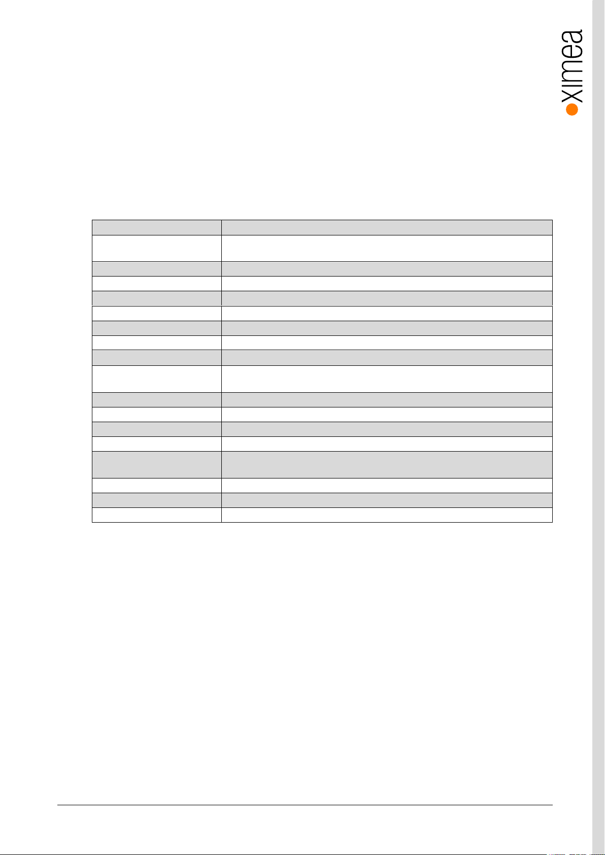
Industry standard interface
Off the shelf components can be used – no ‘frame grabber’
Optional EF lens mount
Canon lenses controllable from software (focus and aperture)
Small
Fits into places where no other camera can fit
Powerful
Up to 64Gb/s (xiB-64)
Fast
High speed, high frame rate: up to 3500+fps (depending on the camera model)
Robust
Full metal housing, no sheet metal covers
Connectivity
Programmable opto-isolated I/O, and non-isolated digital input and output. 4 status LEDs
Compatibility
Support for Windows, Linux and MacOS, various Image Processing Libraries
Software interfaces
GenICam / GenTL and highly optimized xiAPI SDK
Economical
Excellent value and price, low TCO and fast ROI
Low latency
Computer CPU not involved in data transfer, latency from camera to memory is low
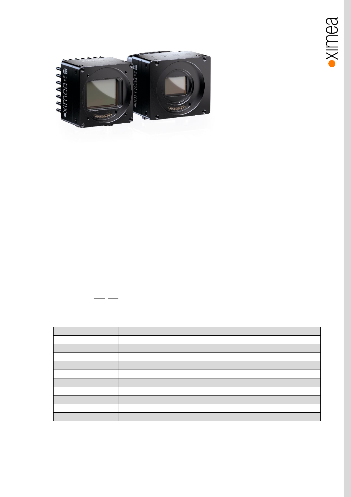
2. xiB Camera Series
Figure 2-1 xiB and xiB-64 camera with heat sinks.
2.1. What is xiB
xiB [
ksi-bee: or sai-bee:]
• Small footprint
• High speed computer interface
• Sensors for xiB: 12, 20, and 50 Mpixel CMOSIS CMOS sensors
• Sensors for xiB-64: 1, 12 Mpixel CMOSIS and Luxima CMOS sensors
• frame rates: 50 MP @ 30 fps to 1 MP @ 3,500+ fps
The XiB camera line uses a PCI Express (PCIe) computer interface which eliminates the need for a framegrabber. Currently, PCIe
generations 2 and 3 are implemented for the xiB and xiB-64 camera lines. As a result, low latency communication between the
camera head and host computer is achieved. Direct Memory Access (DMA) engine is utilized for data transfer between
the camera and PC memory, reducing the CPU load to almost negligible values compared to other protocols.
Off the shelf hardware can be used for camera to computer interfaces, but testing was limited to the items discussed in this
manual. See section 3.10 - 3.12 for materials needed to interface your camera to the computer. Both copper (10m) and fiber
optic (>100m) cables are available for interfaces.
2.2. Advantages
is a compact PCI express Industrial camera family with outstanding features:
table 2-1, advantages
xiB & xiB-64 - Technical Manual Version 1.06
10
Sensor Technology
CMOS, Global shutter
Acquisition Modes
Continuous, software and hardware trigger, limited fps, triggered exposure and burst,
exposure controlled by trigger length
Partial Image Readout
ROI, Skipping and Binning modes supported (model specific)
Image data formats
8, 10 or 12 bit RAW pixel data
Color image processing
Host based de-Bayering, sharpening, Gamma, color matrix, true color CMS
Hot/blemish pixels correction
On camera storage of more than 5000 pixel coordinates, host assisted correction
Auto adjustments
Auto white balance, auto gain, auto exposure
Flat field corrections
Host assisted pixel level shading and lens corrections
Image Data and Control Interface
iPass external PCIe connector (Gen2 x4 for xiB, and Gen3 x8 for xiB-64)
General Purpose I/O
2x opto-isolated input, 2x opto-isolated output, and 4 non-isolated I/O, 4X user
configurable LEDs
Signal conditioning
Programmable debouncing time
Synchronization
Hardware trigger input, software trigger, exposure strobe output, busy output, ..
Housing and lens mount
Optional Canon EF mount available
Power requirements
1
12-24V input, 9-29W
Environment
Operating 0°C to 50°C on housing, RH 80% non-condensing, -30°C to 60°C storage
Ingress Protection: IP40
Operating systems
Windows 10 (x86 and x64), Linux Ubuntu, MacOS 10.8
Software support
xiAPI SDK, adapters and drivers for various image processing packages
Firmware updates
Field firmware updatable
2.3. PCI Express Vision Camera Applications
• Automation
• High speed inspection
• Ultra-fast 3D scanning
• Material and Life science microscopy
• Ophthalmology and Retinal imaging
• Broadcasting
• Fast process capture, e.g. golf club swings
• Aerial Imaging
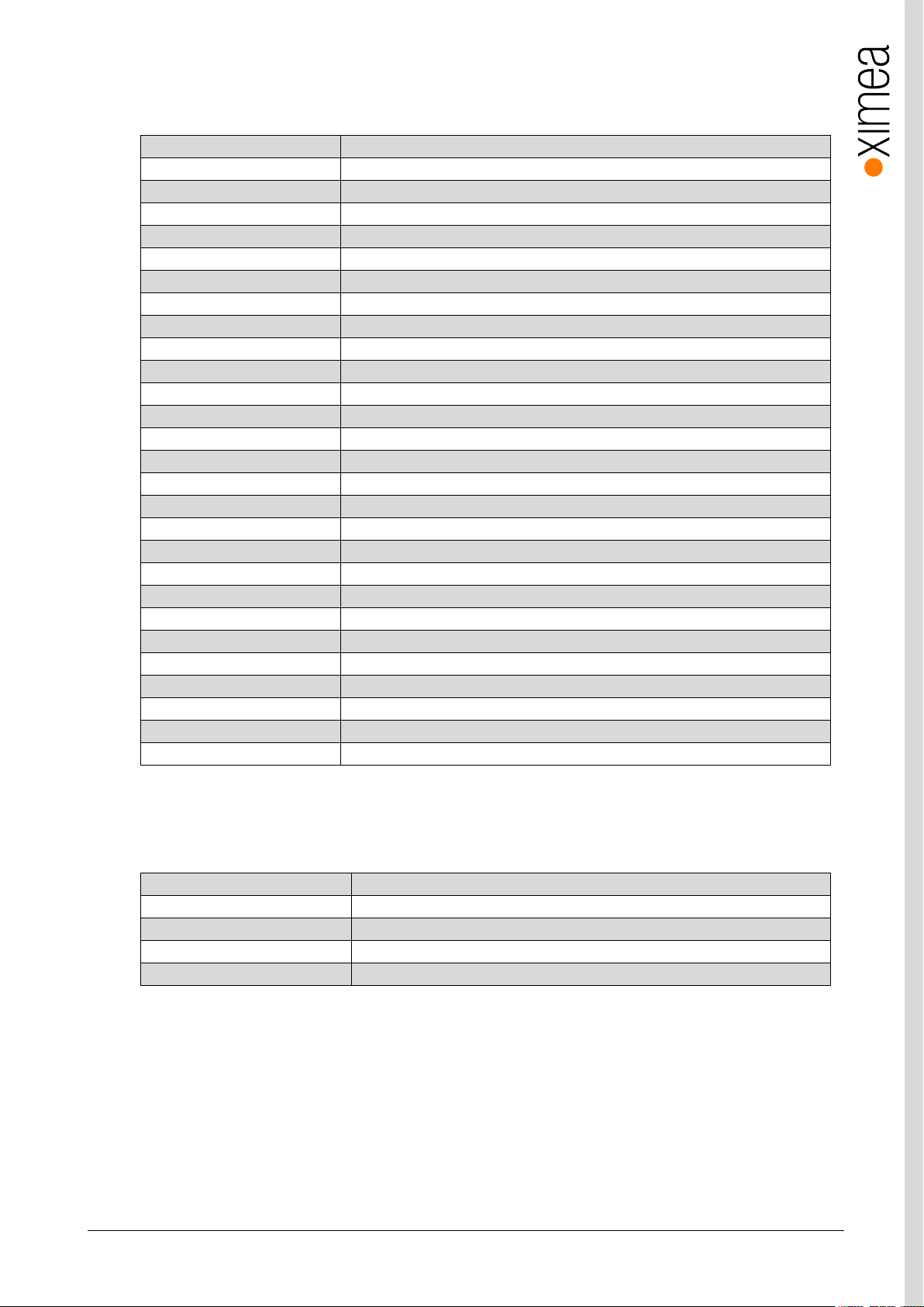
2.4. Common features
table 2-2, common features
Note: 1) Power consumption is model specific

xiB & xiB-64 - Technical Manual Version 1.06
11
2.5. Model Nomenclature
Part number convention for the different models:
xiB family
CBxxxyG-zz
xiB-64 family
CBxxxyG-zz-X8G3
CB xiB and xiB-64 family name
xxx: Resolution in 0.1 MPixel. E.g. 1.3 MPixel Resolution: xxx = 013
y: y=C: color model
y=M: black & white model
y=R: black & white, Infrared-extended model
G: Global shutter (all xiB & xiB-64 cameras are global shutter)
zz: Vendor of the sensor
zz = CM: CMOSIS
zz = LX: Luxima
xiB & xiB-64 - Technical Manual Version 1.06
12
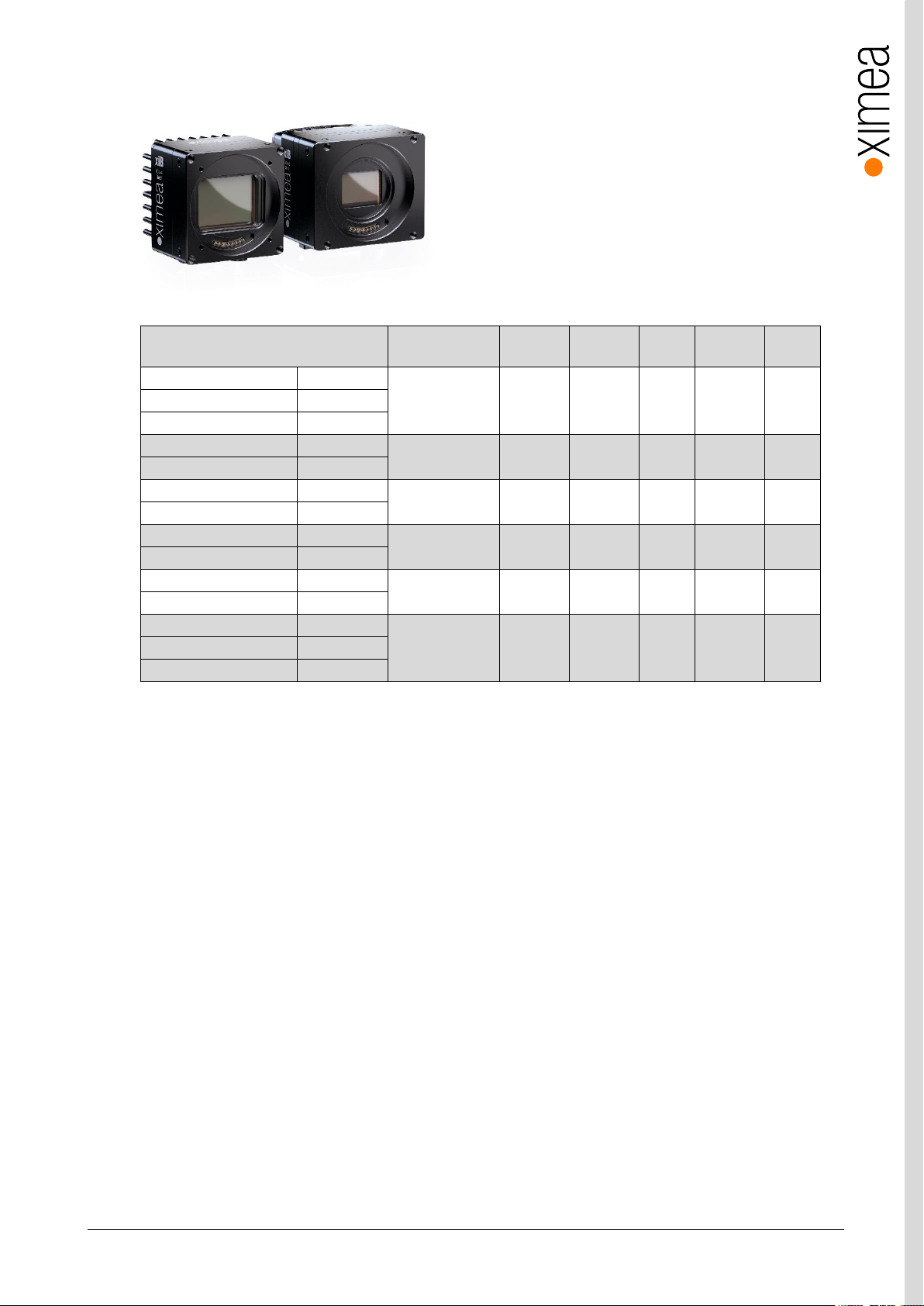
Model Resolution
Pixel size
ADC [bit]
DR
Sensor
diagonal
FPS
1
CB120MG-CM
b/w
4096 x 3072
5.5 µm
8/10/12
60 dB
28.1 mm
133
CB120CG-CM
Color
CB120RG-CM
b/w NIR
CB200MG-CM
b/w
5120 x 3840
6.4 µm
12
66 dB
41 mm
32
CB200CG-CM
Color
CB500MG-CM
b/w
7920 x 6004
4.6 µm
12
64 dB
45.6 mm
30
CB500CG-CM
Color
CB013MG-LX-X8G3
b/w
1280 x 864
13.7 µm
10
60 dB
21.1 mm
3500+
CB013CG-LX-X8G3
Color
CB019MG-LX-X8G3
b/w
1920 x 1080
10.0 µm
10
60 dB
22 mm
2500
CB019CG-LX-X8G3
Color
CB120MG-CM-X8G3
b/w
4096 x 3072
5.5 µm
8/10/12
60 dB
28.1 mm
330
CB120CG-CM-X8G3
Color
CB120RG-CM-X8G3
b/w NIR
2.6. Models Overview, sensor and models
table 2-3, models overview
Note: 1) Full resolution, RAW8 format
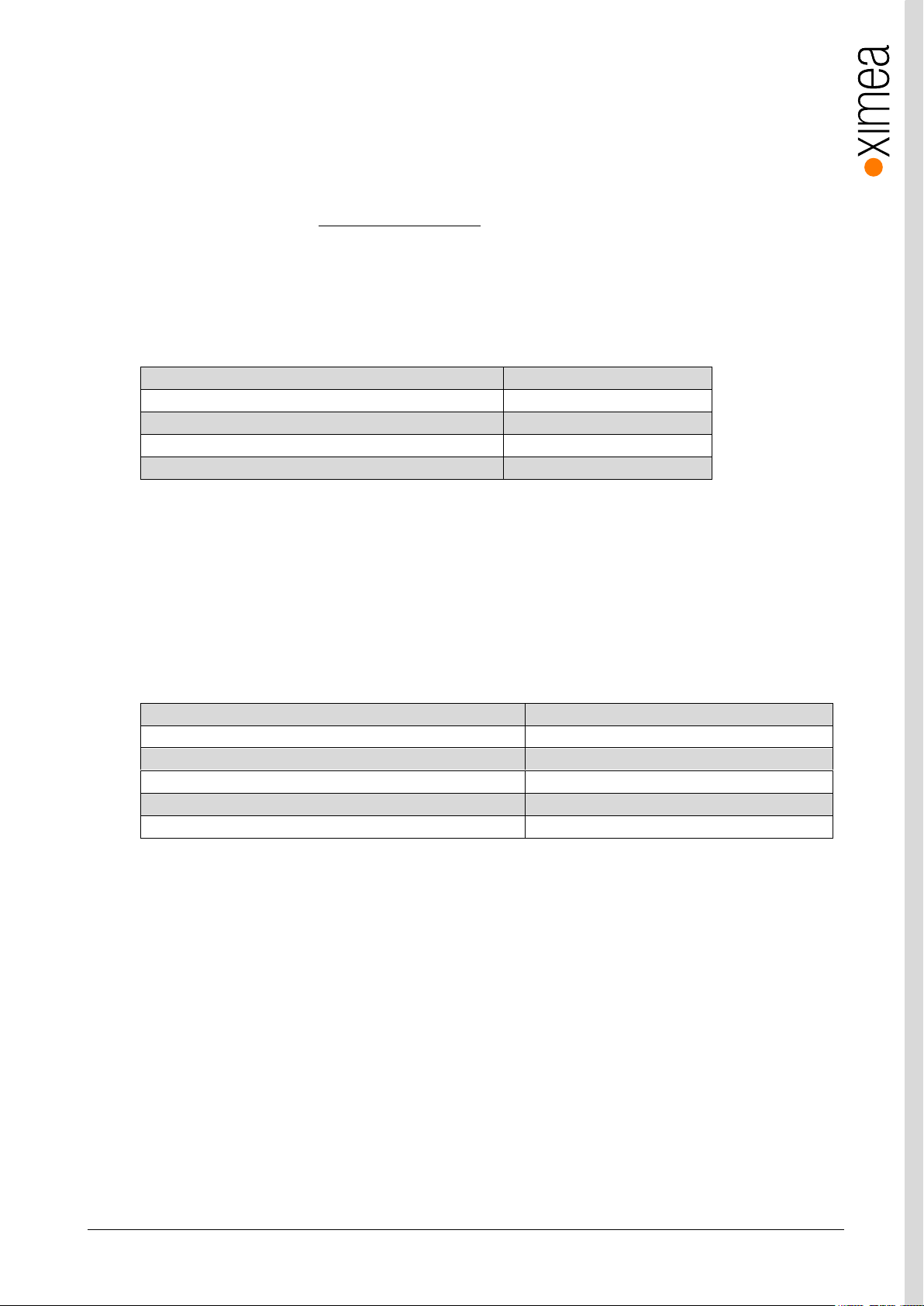
2.7. Options
Most models are available as a board level version, please inquire
The Canon EF mount allows control of focus and aperture settings via software.
xiB & xiB-64 - Technical Manual Version 1.06
13
Item P/N
Description
MECH-60MM-BRACKET-T
xiB series tripod mounting bracket
MECH-60MM-EF-ADAPTER-KIT
1
xiB / xiT Canon EF-Mount Adapter
MECH-60MM-HEATSINK-KIT1
xiB Heatsink kit
CB-X8G3-FAN-COOLER-KIT1
xiB-64 Heatsing Fan Cooler with Screws Kit
LA-C-MNT-60MM-KIT
C-mount lens adapter kit without filter glass
LA-C-MNT-60MM-BK7-KIT
C-mount lens adapter kit with BK7 filter glass
LA-C-MNT-60MM-IR650-KIT
C-mount lens adapter kit with IR650 filter glass
CBL-CB-PWR-SYNC-3M0
3.0m xiB series I/O Sync and power cable
CBL-MT-PWR-SYNC-3M0
3.0m xiT/xiB-64 series I/O Sync and AUX power cable
PEX4-G2-COP
PCIe Gen.2 x4 extender host adapter for copper cables
PEX4-G2-COP-X2
PCIe Gen.2 x4 extender host adapter for copper cables, 2 ports.
PEX4-G2-FIB
PCIe Gen.2 x4 extender host adapter for fiber optics cables
PEX8-G3-X1-DOL
PCIe Gen.3 x8 extender host adapter for copper and fiber optics cables
PEX8-G3-X2-OSS
PCIe Gen.3 x8 dual port extender host adapter for copper and fiber optics cables
CBL-PCI-COP-1M0
1.0m PCIe Gen.2 x4, copper cable
CBL-PCI-COP-3M0
3.0m, PCIe Gen.2 x4, copper cable
CBL-PCI-COP-5M0
5.0m, PCIe Gen.2 x4, copper cable
CBL-PCI-COP-7M0
7.0m, PCIe Gen.2 x4, copper cable
CBL-PCI-FIB-10M0
10.0m, PCIe Gen.2 x4, fiber optics cable
CBL-PCI-FIB-20M0
20.0m, PCIe Gen.2 x4, fiber optics cable
CBL-PCI-X8G3-COP-3M0
3.0m PCIe Gen.3 x8, copper cable
CBL-PCI-FIB-10M0
10.0m PCIe Gen.2 x4, optical cable
CBL-PCI-FIB-20M0
20.0m PCIe Gen.2 x4, optical cable
CBL-PCI-X8G3-FIB-10M0
10.0m PCIe Gen.3 x8 optical cable
CBL-PCI-X8G3-FIB-20M0
20.0m PCIe Gen.3 x8 optical cable
BACS30M-24-C8
power supply (30W)
BACS60M-24-C8
xiB series power supply (60W, 24V)
Item P/N
Description
A-CB-X8G3-FAN-COOLER-KIT
Assembly Service for CB-X8G3-FAN-COOLER-KIT
A-MECH-60MM-EF-ADAPTER-KIT
Assembly Service for MECH-60MM-EF-ADAPTER-KIT
A-MECH-60MM-HEATSINK-KIT
Assembly Service for MECH-60MM-HEATSINK-KIT
A-LA-C-MNT-60MM-KIT
Assembly Service for LA-C-MNT-60MM-xxx-KIT
2.8. Accessories
The following accessories are available:
table 2-4, accessories
Notes: 1) This kits are sold separately, however it is possible to order assembling during production. These assemblies
are sold separately. Additional assemblies purchased along with a camera can be added to the order at time of
purchase for assembly with camera head. See table 2-5
table 2-5, assembly options
xiB & xiB-64 - Technical Manual Version 1.06
14
Description
Value
Optimal ambient temperature operation
+10 to +25 °C
Ambient temperature operation
+0 to +50 °C
Ambient temperature for storage and transportation
-25 to +70 °C
Relative Humidity, non-condensing
80 %
Description
Value
Interpolation
Proprietary
White balance coefficients ranges
0.0 to 3.9
Sharpness filter
-400 to 400 %
Gamma
0.3 to 1.0
Full color correction matrix (3+1)x3 coefficients ranges
-3.9 to 3.9
3. Hardware Specification
3.1. Power Supply
The xiB and xiB-64 cameras are powered via their respective sync cables (CBL-CB-PWR-SYNC-3M0 (xiB) and CBL-MT-PWRSYNC-3M0 (xiB-64)). See section 3.8 xiB, xiB-64 PCIe Interface for details on the camera connector and input requirements.
The power required to run the camera varies on the camera model from 9-29W. Ximea sells a power supply to run the cameras.
PN: BACS30M-24-C8 or BACS60M-24-C8.
3.2. General Specification
3.2.1. Environment
table 3-1, environment
Housing temperature must not exceed +65°C. The following parameters are not guaranteed if the camera is operated outside
the optimum range:
• Dark current
• Dynamic Range
• Linearity
• Acquisition and readout noise
• S/N ratio, durability
3.2.2. Firmware / Host driver / API features
table 3-2, firmware / API features
More details on API/SDK features are available at XIMEA support pages: http://www.ximea.com/support
xiB & xiB-64 - Technical Manual Version 1.06
15
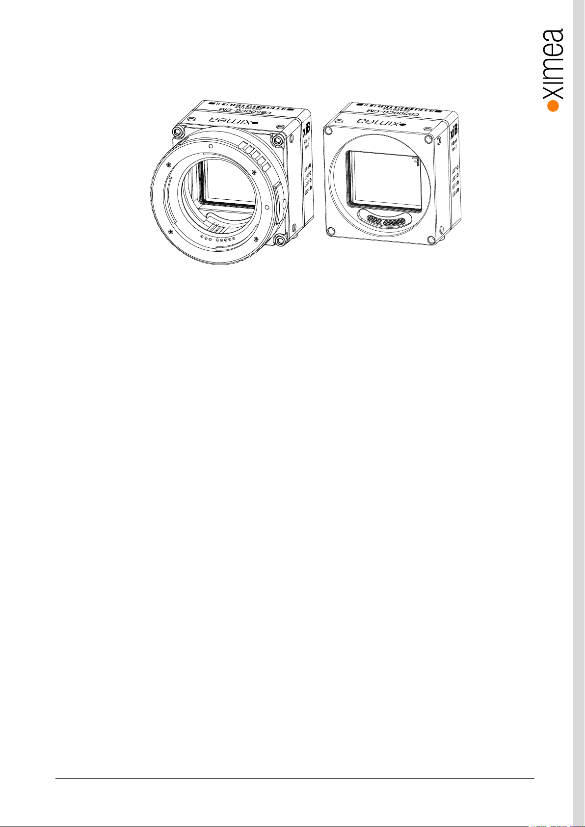
3.3. Lens Mount
The xiB & xiB-64cameras are compatible with the Canon EF mount.
figure 3-1, xiB camera with/without the optional EF-Mount Adapter
The cameras are optionally delivered with or without outer EF-Mount Adapter.
Note: The distance between the outer EF-Mount Adapter and the active sensor surface is 44 mm and when no EF-Mount
Adapter is included it is 13.4 mm.
Cameras with 4/3” or smaller sensor format can also be equipped with C-mount lens adapter.
xiB & xiB-64 - Technical Manual Version 1.06
16
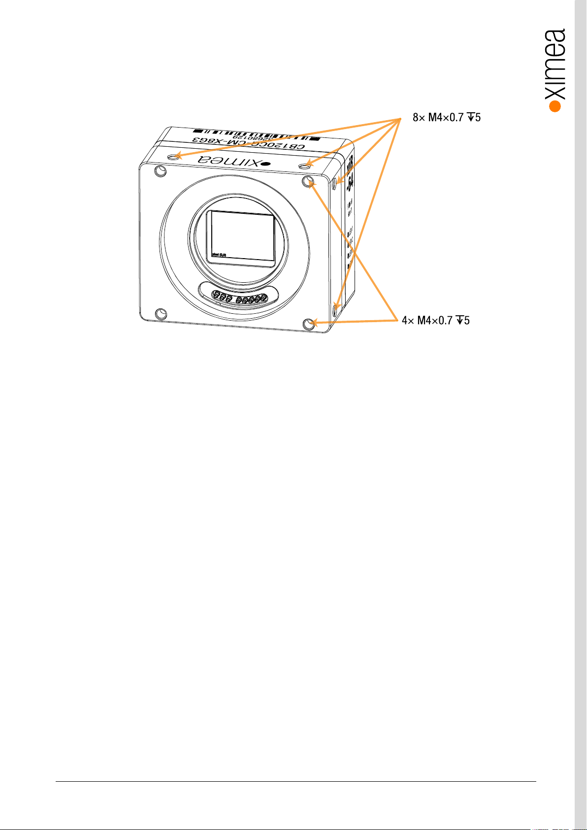
3.4. Mounting points
Mounting points available to the customer are shown below. All are M4 thread. Four mounting points at the front panel are used
for the EF-mount adapter when installed.
Figure 3-2, drawing demonstrating the mounting hole positions. Camera shown without EF mount.
3.5. Optical path
No filter glass is added by Ximea. All windows are applied by the sensor vendor – see sensor vendor data sheets for optical path
details.
xiB & xiB-64 - Technical Manual Version 1.06
17
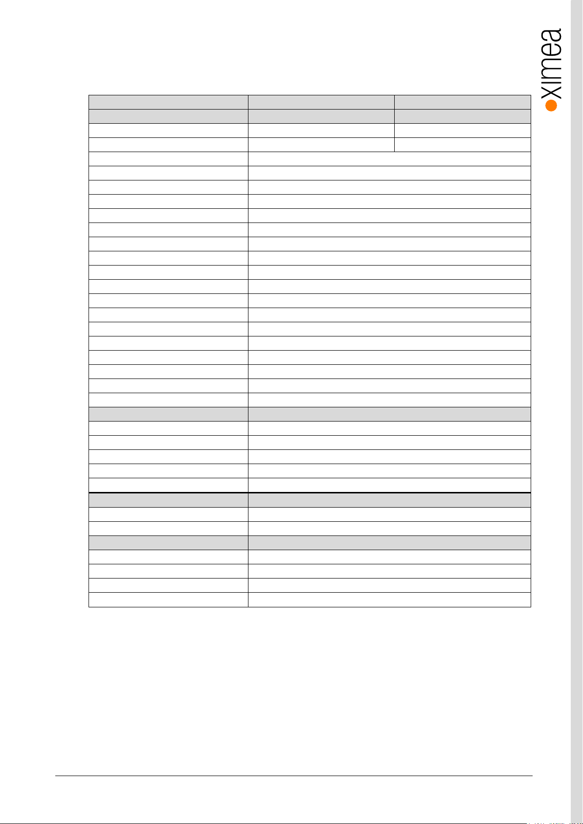
xiB model
CB120CG-CM
CB120MG-CM
CB120RG-CM
Sensor parameter
Part number
CMV12000-2E5C1PA
CMV12000-2E5M1PA
CMV12000-2E12M1PA
Color filter
RGB Bayer mosaic
None
None
Type
Global shutter
Pixel Resolution (W x H) [pixel]
4096 x 3072
Active area size (W x H) [mm]
22.5 x 16.9mm
Sensor diagonal [mm]
28.16mm
Optical format [inch]
1”
Pixel Size [µm]
5.5µm
ADC resolution [bit]
8, 10, 12
FWC [ke-]
13.5
Dynamic range [dB]
60
SNR Max [dB]
TBD
Conversion gain [e-/LSB12]
TBD
Dark noise [e-]
TBD
Dark current [e-/s]
22 @ RT 10-bit mode
DSNU [e-]
2 in 10-bit mode
PRNU %
<1.27%
Linearity [%]
TBD
Shutter efficiency
1/50,000
Micro lenses
Yes
Camera parameters
Digitization [bit]
8, 10, 12
Supported bit resolutions [bit/pixel]
8, 9, 10, 11, 12, 16
Exposure time (EXP)
0.019 – 3500 ms
Variable Gain Range (VGA) [dB]
0-12dB
1
Refresh rate (MRR) [fps]
133/103/86 at 8/10/12 bit
Power consumption
2
Stand by [W]
7.39
Maximum [W]
9.9
Dimensions/Mass
height [mm]
60
width [mm]
60
depth [mm]
36 (w/o EF-Mount Adapter)
mass [g]
159 (w/o EF-Mount Adapter)
3.6. Model Specific Characteristics
3.6.1. CB120xG-CM
3.6.1.1. Sensor and camera parameters
table 3-3, CB120xG-CM, sensor and camera parameters
Notes: 1) Analog gain has only discrete steps.
2) Measured at 24V with connected 10m fiber optical PCIe cable CBL-PCI-FIB-10M0. Optical cable
consumption is about 1.25W.
xiB & xiB-64 - Technical Manual Version 1.06
18
Binning/skipping
pixels
Bit/px
fps
1x1/1x1
4096 x 3072
8
133
1x1/2x2
2048 x 1536
8
446
2x2/1x1
2048 x 1536
8
200
1x1/1x1
4096 x 3072
10
110
1x1/2x2
2048 x 1536
10
446
2x2/1x1
2048 x 1536
10
267
1x1/1x1
4096 x 3072
12
92
1x1/2x2
2048 x 1536
12
443
2x2/1x1
2048 x 1536
12
267
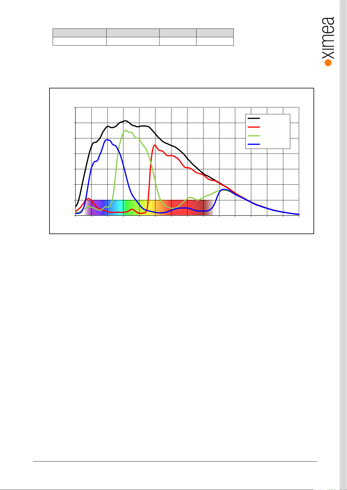
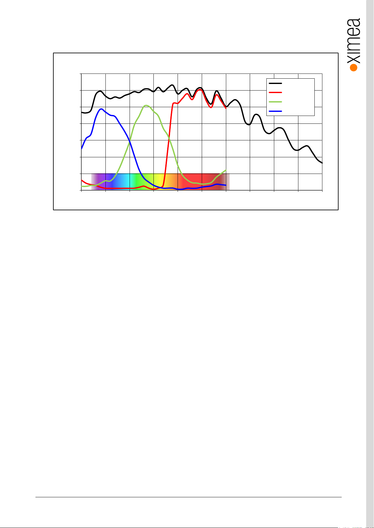
0%
10%
20%
30%
40%
50%
60%
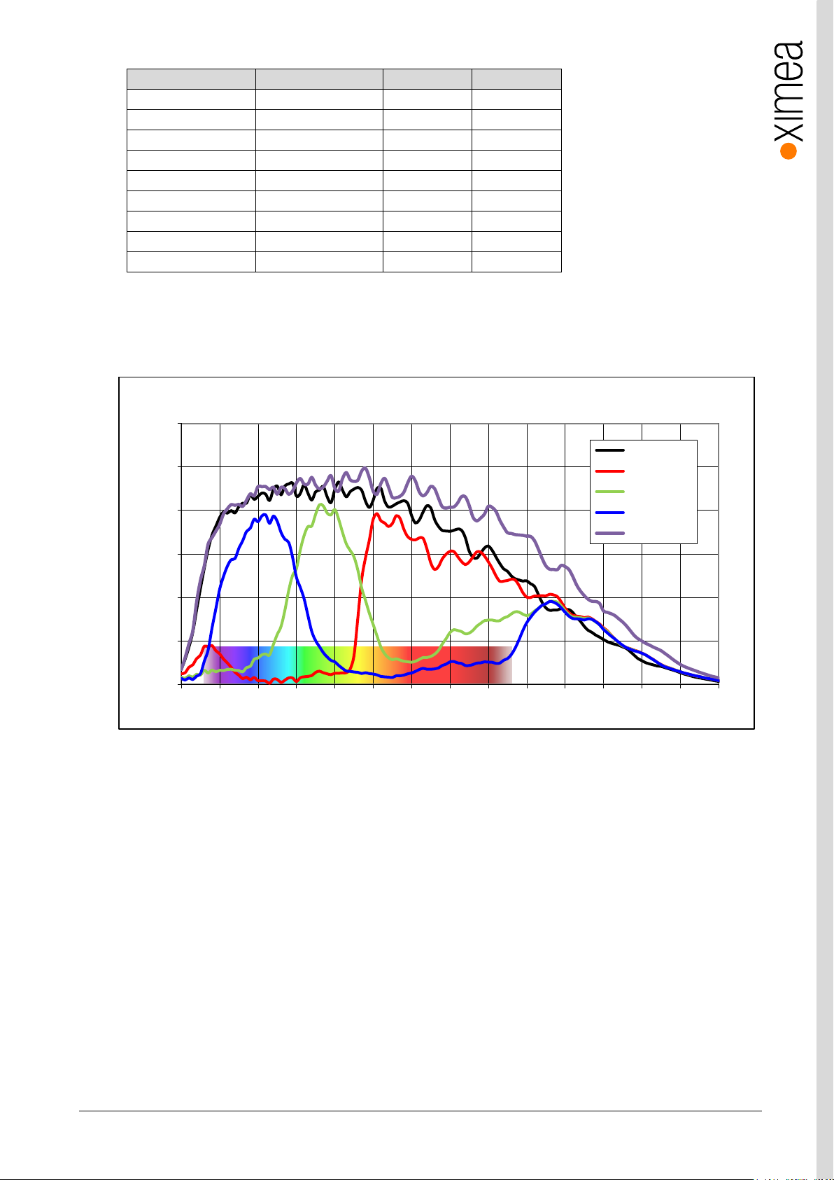
350 400 450 500 550 600 650 700 750 800 850 900 950 1000 1050
Quantum Efficiency (%)
Wavelength (nm)
CMV12000 - Spectral Response
Monochrome
Red Bayer
Green Bayer
Blue Bayer
NIR
table 3-4, CB120xG-CM, standard readout modes
3.6.1.2. Quantum efficiency curves [%]
figure 3-3, CMV12000-mono, color and NIR, quantum efficiency curve, ©CMOSIS
xiB & xiB-64 - Technical Manual Version 1.06
19
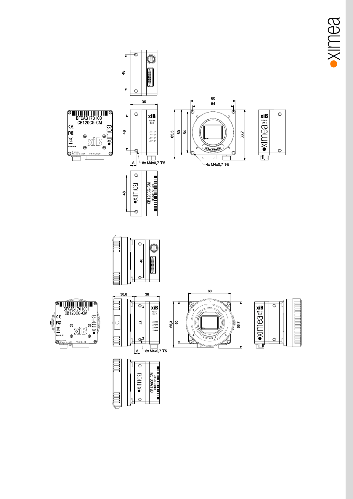
3.6.1.3. Dimensional drawings CB120xG-CM
figure 3-4, dimensional drawing CB120xG-CM
figure 3-5, dimensional drawing CB120xG-CM, with EF-mount adapter

xiB & xiB-64 - Technical Manual Version 1.06
20
feature
Note
Binning
Yes 2x2
Skipping
Yes 2x2
ROI
Vertical cropping results in increased read speed, horizontal reduces data transfer
HW Trigger
Trigger with overlap (see 4.3.2 Trigger controlled Acquisition/Exposure)
HDR
Not available
3.6.1.4. Referenced documents
CMOSIS datasheet CMV12000 datasheet v2.11
3.6.1.5. Sensor features
table 3-5, sensor features available
xiB & xiB-64 - Technical Manual Version 1.06
21
xiB model
CB200CG-CM
CB200MG-CM
Sensor parameter
Part number
CMV20000-1E5C1PA
CMV20000-1E5M1PA
Color filter
RGB Bayer mosaic
None
Type
Global shutter
Pixel Resolution (W x H) [pixel]
5120 x 3840
Active area size (W x H) [mm]
32.8 x 24.6mm
Sensor diagonal [mm]
40.96mm
Optical format
Full frame
Pixel Size [µm]
6.4µm
ADC resolution [bit]
12
FWC [ke-]
15
Dynamic range [dB]
66
SNR Max [dB]
TBD
Conversion gain [e-/LSB12]
TBD
Dark noise [e-]
TBD
Dark current [e-/s]
125e-/s @ RT
DSNU [e-]
10
PRNU %
TBD
Linearity [%]
TBD
Shutter efficiency
1/50,000
Micro lenses
Yes
Camera parameters
Digitization [bit]
12
Supported bit resolutions [bit/pixel]
8, 9, 10, 11, 12, 16
Exposure time (EXP)
0.094 – 1050 ms
Variable Gain Range (VGA) [dB]
0- 2.551
Refresh rate (MRR) [fps]
32 @ 12 bit
Power consumption
Stand by [W]
6.6
Maximum [W]
9.0
Dimensions/Mass
height [mm]
60
width [mm]
60
depth [mm]
38 (w/o EF mount)
mass [g]
164 (w/o EF mount)
3.6.2. CB200xG-CM
3.6.2.1. Sensor and camera parameters
table 3-6, CB200xG-CM, sensor and camera parameters
Notes: 1) Analog gain has only several discrete steps.
2) Measured at 24V with connected 10m fiber optical PCIe cable CBL-PCI-FIB-10M0. Optical cable
consumption is about 1.25W.
xiB & xiB-64 - Technical Manual Version 1.06
22
Binning/skipping
pixels
Bit/px
fps
1x1/1x1
5120 × 3840
8, 10, 12
32.5
0%
10%
20%
30%
40%
50%
60%
70%
350 400 450 500 550 600 650 700 750 800 850 900 950 1000 1050
Quantum Efficiency (%)
Wavelength (nm)
CMV20000 - Spectral Response
Monochrome
Red Bayer
Green Bayer
Blue Bayer
table 3-7, CB200xG-CM, standard readout modes
3.6.2.2. Quantum efficiency curves [%]
figure 3-6, CMV20000 mono and color, quantum efficiency curve, ©CMOSIS
xiB & xiB-64 - Technical Manual Version 1.06
23
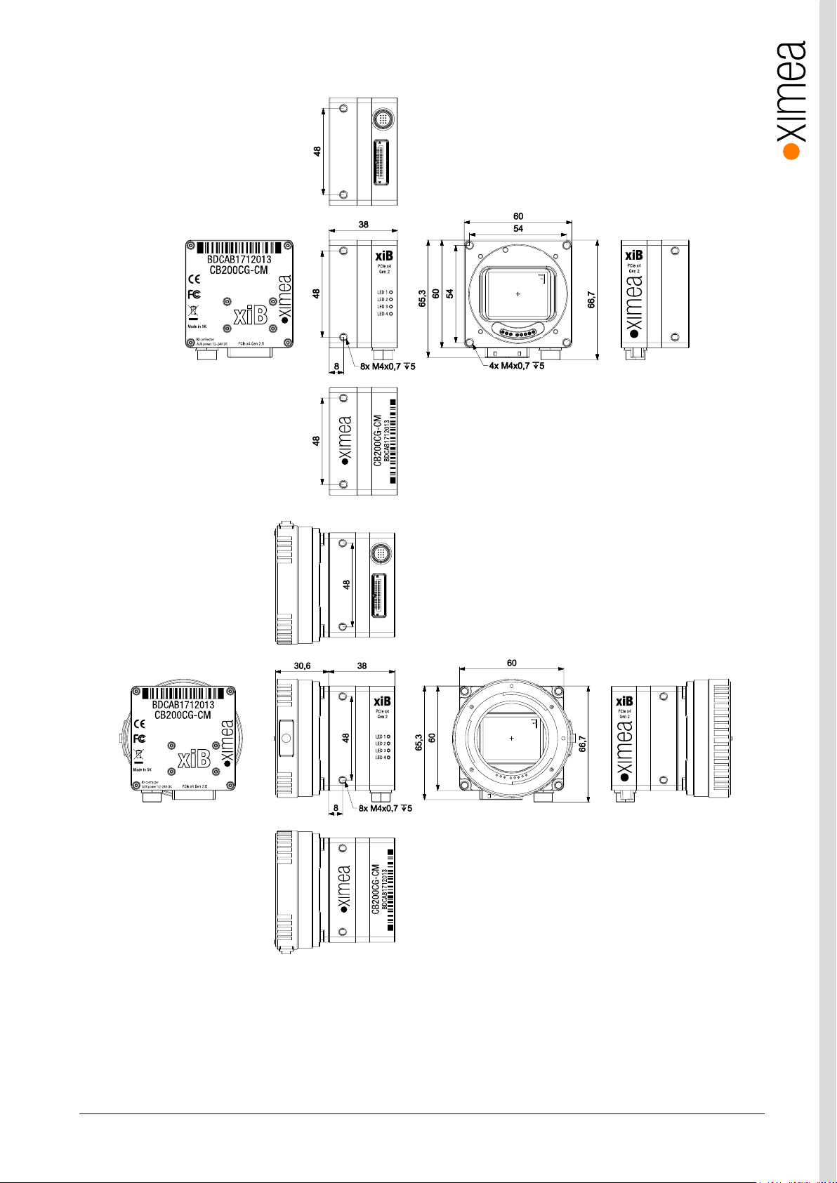
3.6.2.3. Dimensional drawings CB200xG-CM
figure 3-7, dimensional drawing CB200xG-CM with EF-mount adapter
figure 3-8, dimensional drawing CB200xG-CM with EF-mount adapter

xiB & xiB-64 - Technical Manual Version 1.06
24
feature
Note
Binning
No
Skipping
No
ROI
Vertical cropping results in increased readout speed, horizontal reduces data transfer
HW Trigger
Trigger without overlap usable (see 4.3.2 Trigger controlled Acquisition/Exposure)
HDR
Supported
3.6.2.4. Referenced documents
CMOSIS datasheet CMV20000 v2.3_2
3.6.2.5. Sensor features
table 3-8, sensor features available
xiB & xiB-64 - Technical Manual Version 1.06
25
xiB model
CB500CG-CM
CB500MG-CM
Sensor parameter
Part number
CMV50000-1E3C1PA
CMV50000-1E3M1PA
Color filter
RGB Bayer mosaic
None
Type
Global shutter
Pixel Resolution (H × W) [pixel]
7920 x 6004
Active area size (H × W) [mm]
36.4 x 27.6
Sensor diagonal [mm]
45.72
Optical format [inch]
Slightly bigger than ‘full frame’
Pixel Size [µm]
4.6
ADC resolution [bit]
12
FWC [ke-]
14.5
Dynamic range [dB]
64
SNR Max [dB]
41.6
Conversion gain [e-/LSB12]
TBD
Dark noise [e-]
8.8
Dark current [e-/s]
33
DSNU [e-]
24.5
PRNU %
<1.0
Linearity [%]
TBD
Shutter efficiency 1/PLS
1/18000
Micro lenses
yes
Camera parameters
Digitization [bit]
12
Supported bit resolutions [bit/pixel]
8, 9, 10, 11, 12, 16
Exposure time (EXP)
TBD
Variable Gain Range (VGA) [dB]
0-12
Refresh rate (MRR) [fps]
32 @ 8-bit/pixel
Power consumption
typical [W]
9
Maximum [W]
9.5
Mechanical
height [mm]
60
width [mm]
60
depth [mm]
37.8 (w/o EF mount)
weight [g]
170 (w/o EF mount)
3.6.3. CB500xG-CM
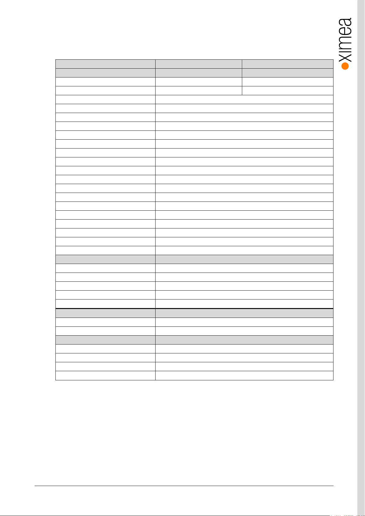
3.6.3.1. Sensor and camera parameters
table 3-9, CB500xG-CM, sensor and camera parameters
Notes: 1) Analog gain has only several discrete steps.
xiB & xiB-64 - Technical Manual Version 1.06
26
Binning/skipping
pixels
Bit/px
fps
1x1/1x1
7920 × 6004
8
30.9
1x1/1x1
7920 × 6004
10
28.9
1x1/1x1
7920 × 6004
12
24.1
1x1/1x2
7920 × 3002
8
60.5
1x1/1x2
7920 × 3002
10
57.1
1x1/1x2
7920 × 3002
12
47.9
1x1/2x2
3960 × 3000
8
61.4
1x1/2x2
3960 × 3000
10
61.4
1x1/2x2
3960 × 3000
12
61.4
2x2/1x1
3960 × 3000
8
30.8
2x2/1x1
3960 × 3000
10
30.8
2x2/1x1
3960 × 3000
12
30.8
0%
10%
20%
30%
40%
50%
60%
70%
350 400 450 500 550 600 650 700 750 800 850 900 950 1000 1050
Quantum Efficiency (%)
Wavelength (nm)
CMV50000 - Spectral Response
Monochrome
Red Bayer
Green Bayer
Blue Bayer
table 3-10, CB500xG-CM, standard readout modes
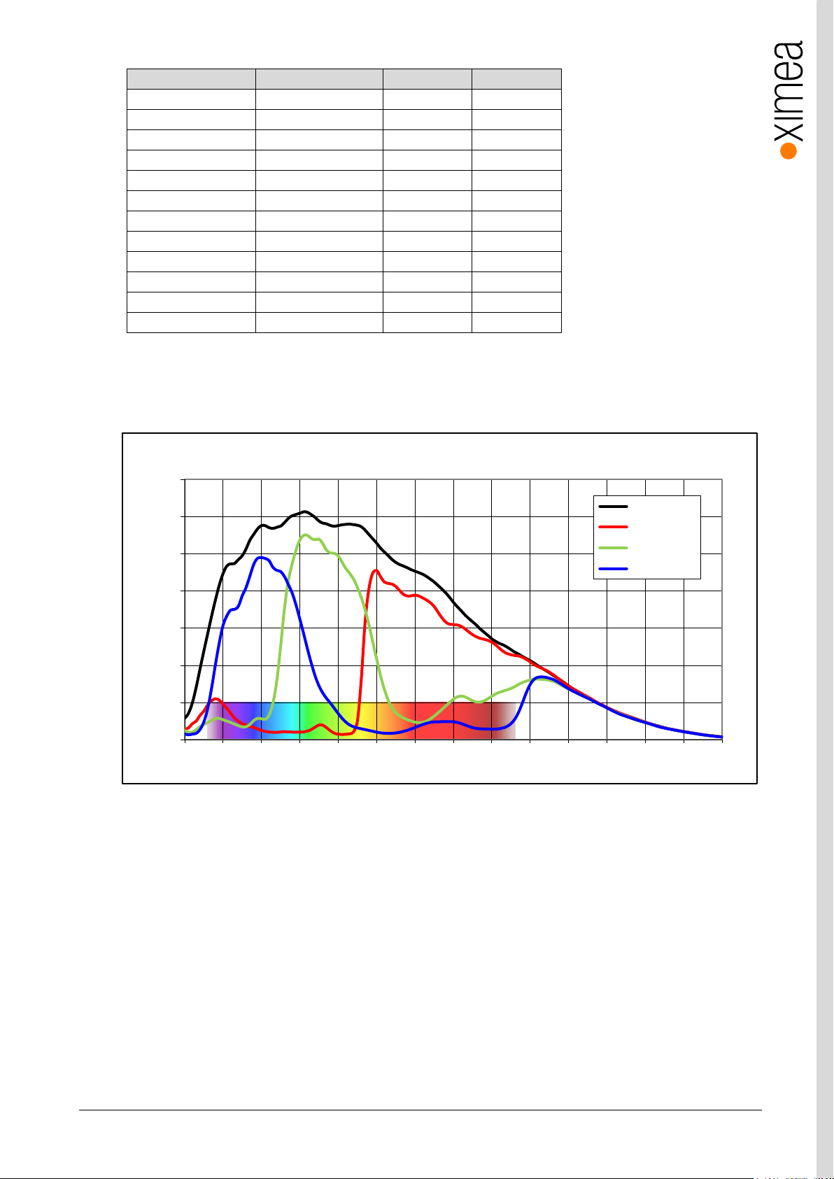
3.6.3.2. Quantum efficiency curves [%]
figure 3-9 CMV50000 Quantum Efficiency ©CMOSIS
xiB & xiB-64 - Technical Manual Version 1.06
27
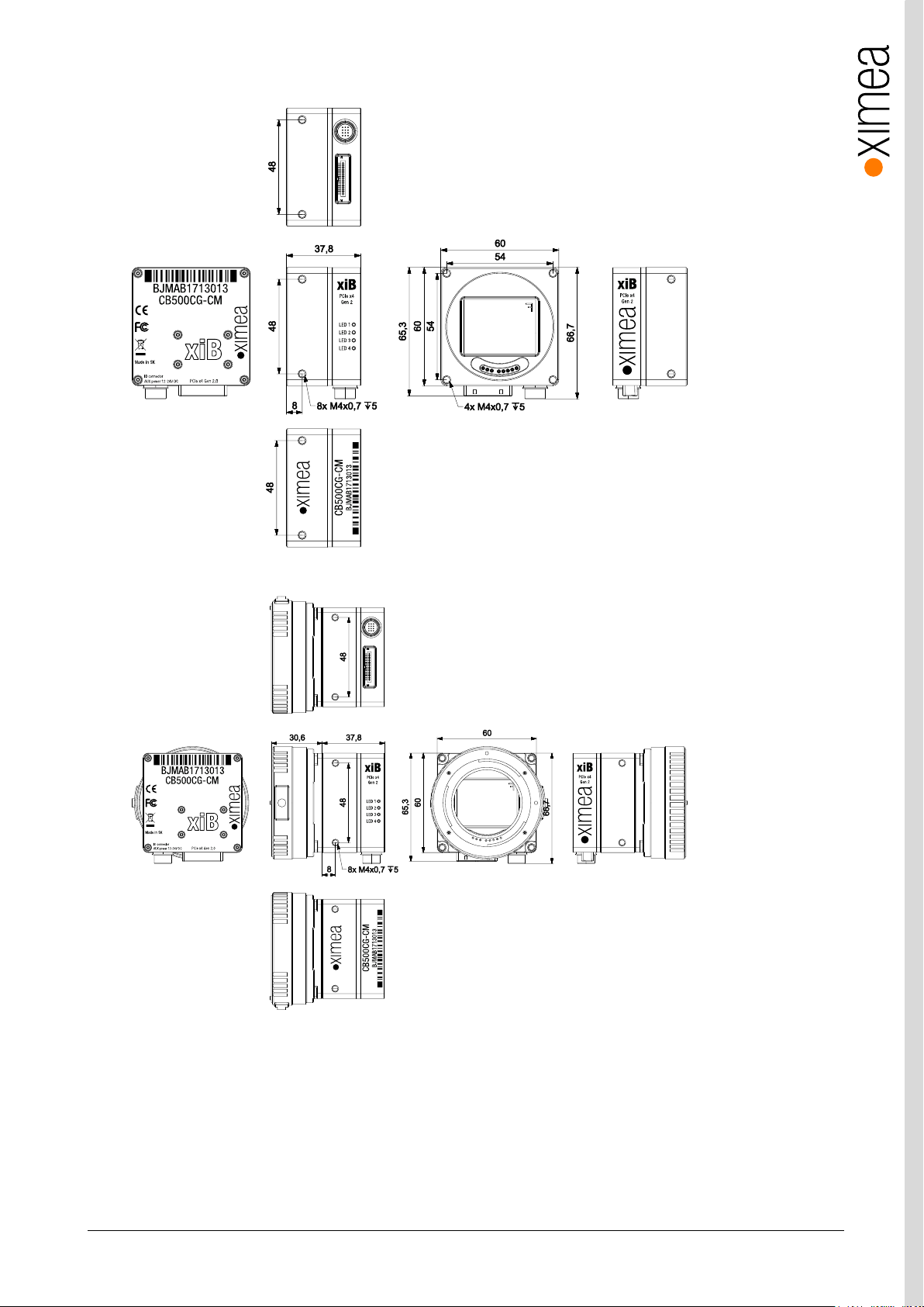
3.6.3.3. Dimensional drawings CB500xG-CM (with and without EF mount)
figure 3-10, dimensional drawing CB500xG-CM w/o EF-mount adapter
figure 3-11, dimensional drawing CB500xG-CM with EF-mount adapter

xiB & xiB-64 - Technical Manual Version 1.06
28
feature
Note
Binning
Yes, 2x2
Skipping
Yes, 2x2
ROI
Vertical cropping results in increased read speed, horizontal reduces data transfer
HW Trigger
Trigger with overlap usable (see 4.3.2 Trigger controlled Acquisition/Exposure)
HDR
Not available
3.6.3.4. Referenced documents
CMOSIS Datasheet CMV50000 v0.11
3.6.3.5. Sensor features
table 3-11, sensor features available
xiB & xiB-64 - Technical Manual Version 1.06
29
xiB-64 model
CB013CG-LX-X8G3
CB013MG-LX-X8G3
Sensor parameter
Part number
LUX13HSC
LUX13HSM
Color filter
RGB Bayer mosaic
None
Type
Global shutter
Pixel Resolution (W x H) [pixel]
1280 × 864
Active area size (W x H) [mm]
17.5 × 11.8
Sensor diagonal [mm]
21.2
Optical format [inch]
4/3”
Pixel Size [µm]
13.7
ADC resolution [bit]
10
FWC [ke-]
20
Dynamic range [dB]
60
SNR Max [dB]
TBD
Conversion gain [e-/LSB12]
TBD
Dark noise [e-]
14
Dark current [e-/s]
TBD
DSNU [e-]
TBD
PRNU %
<1.5
Linearity [%]
TBD
Shutter efficiency 1/PLS
TBD
Micro lenses
TBD
Camera parameters
Digitization [bit]
10
Supported bit resolutions [bit/pixel]
8, 9, 10, 11, 12, 16
Exposure time (EXP)
1µs – 1sec
Variable Gain Range (VGA) [dB]
0-18dB
Refresh rate (MRR) [fps]
3500 (10-bit)
Power consumption
typical [W]
TBD
Maximum [W]
TBD
Mechanical
height [mm]
60
width [mm]
70
depth [mm]
41 (w/o EF-mount adapter and active cooling)
weight [g]
268 (w/o EF-mount adapter and active cooling)
Binning/skipping
pixels
Bit/px
fps
1x1/1x1
1280 × 864
8
3500
3.6.4. CB013xG-LX-X8G3
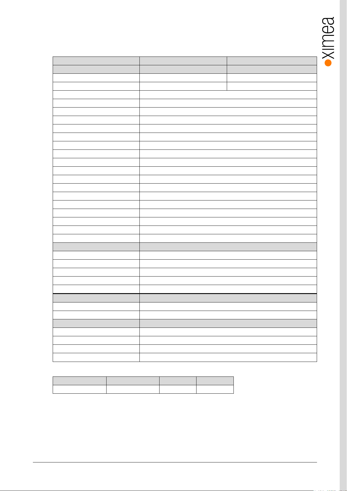
3.6.4.1. Sensor and camera parameters
table 3-12, CB013xG-LX-X8G3, sensor and camera parameters
table 3-13, CB013xG-LX-X8G3, standard readout modes
xiB & xiB-64 - Technical Manual Version 1.06
30
0%
5%
10%
15%
20%
25%
30%
35%
400 450 500 550 600 650 700 750 800 850 900
Quantum Efficiency (%)
Wavelength (nm)
LUX13HS - Spectral Response
Monochrome
Red Bayer
Green Bayer
Blue Bayer
3.6.4.2. Quantum efficiency curves [%]
figure 3-12, LUX13HS quantum efficiency chart ©Luxima
 Loading...