

Page 1

ZCU111 Evaluation Board
User Guide
UG1271 (v1.1) August 6, 2018
Page 2

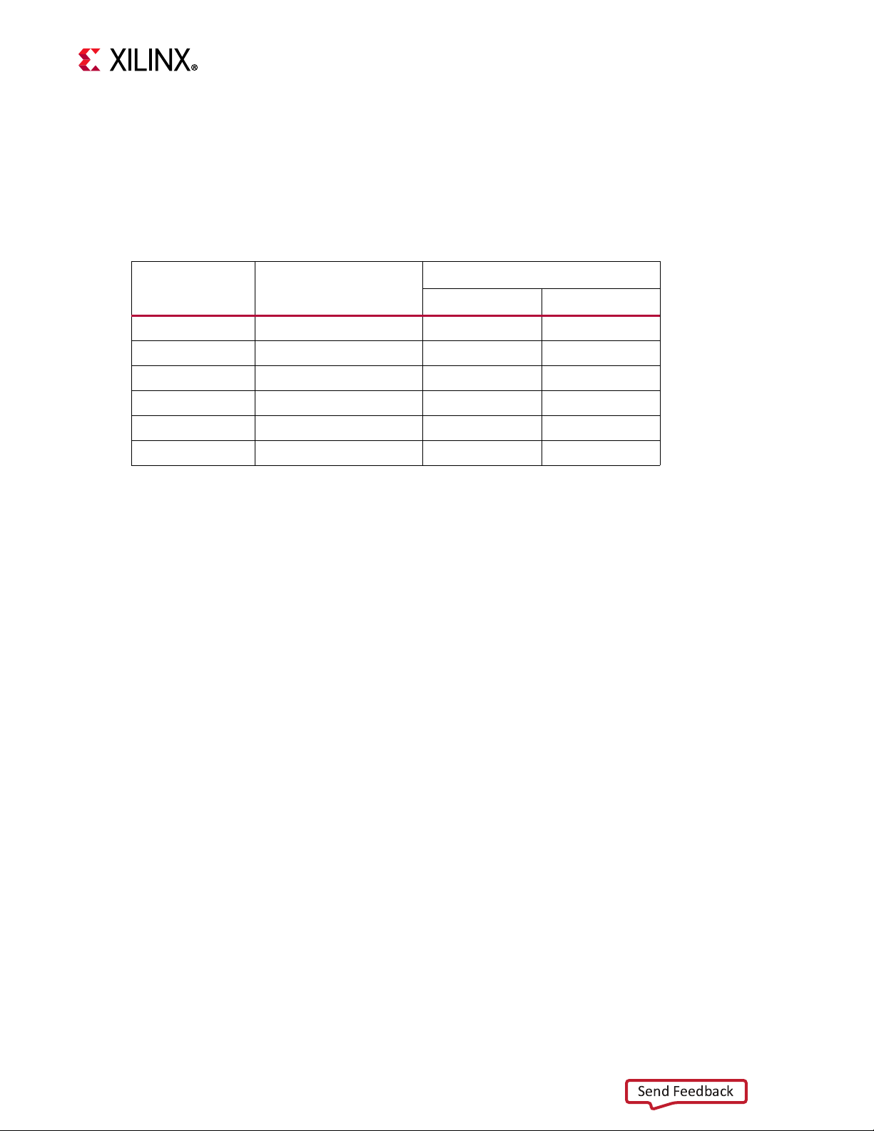
Revision History
Send Feedback
The following table shows the revision history for this document.
Section Revision Summary
8/06/2018 Version 1.1
RF Data Converter Clocking Removed RF Clocking Overview figure.
Figure 3-18 Added capacitor option.
Table 3-18 and Tab le 3- 19 Added optional RFMC and SYSREF capacitor options.
SFP28 Module Connectors
Added note and reference to SNIA Technology
Affiliates website.
06/28/2018 Version 1.0
Initial Xilinx release.
ZCU111 Board User Guide 2
UG1271 (v1.1) August 6, 2018 www.xilinx.com
Page 3

Table of Contents
Send Feedback
Revision History . . . . . . . . . . . . . . . . . . . . . . . . . . . . . . . . . . . . . . . . . . . . . . . . . . . . . . . . . . . . . . . . . . . . 2
Chapter 1: Introduction
Overview . . . . . . . . . . . . . . . . . . . . . . . . . . . . . . . . . . . . . . . . . . . . . . . . . . . . . . . . . . . . . . . . . . . . . . . . 6
Additional Resources . . . . . . . . . . . . . . . . . . . . . . . . . . . . . . . . . . . . . . . . . . . . . . . . . . . . . . . . . . . . . . . 6
Block Diagram . . . . . . . . . . . . . . . . . . . . . . . . . . . . . . . . . . . . . . . . . . . . . . . . . . . . . . . . . . . . . . . . . . . . 7
Board Features . . . . . . . . . . . . . . . . . . . . . . . . . . . . . . . . . . . . . . . . . . . . . . . . . . . . . . . . . . . . . . . . . . . . 7
Board Specifications . . . . . . . . . . . . . . . . . . . . . . . . . . . . . . . . . . . . . . . . . . . . . . . . . . . . . . . . . . . . . . . 9
Dimensions . . . . . . . . . . . . . . . . . . . . . . . . . . . . . . . . . . . . . . . . . . . . . . . . . . . . . . . . . . . . . . . . . . . . . . . . . . . . . . .9
Environmental . . . . . . . . . . . . . . . . . . . . . . . . . . . . . . . . . . . . . . . . . . . . . . . . . . . . . . . . . . . . . . . . . . . . . . . . . . . .10
Operating Voltage . . . . . . . . . . . . . . . . . . . . . . . . . . . . . . . . . . . . . . . . . . . . . . . . . . . . . . . . . . . . . . . . . . . . . . . . .10
Chapter 2: Board Setup and Configuration
Board Component Location. . . . . . . . . . . . . . . . . . . . . . . . . . . . . . . . . . . . . . . . . . . . . . . . . . . . . . . . . 11
Default Jumper and Switch Settings. . . . . . . . . . . . . . . . . . . . . . . . . . . . . . . . . . . . . . . . . . . . . . . . . . 16
Jumpers . . . . . . . . . . . . . . . . . . . . . . . . . . . . . . . . . . . . . . . . . . . . . . . . . . . . . . . . . . . . . . . . . . . . . . . . . . . . . . . . .17
Switches . . . . . . . . . . . . . . . . . . . . . . . . . . . . . . . . . . . . . . . . . . . . . . . . . . . . . . . . . . . . . . . . . . . . . . . . . . . . . . . . .19
RFSoC Device Configuration . . . . . . . . . . . . . . . . . . . . . . . . . . . . . . . . . . . . . . . . . . . . . . . . . . . . . . . . 20
JTAG . . . . . . . . . . . . . . . . . . . . . . . . . . . . . . . . . . . . . . . . . . . . . . . . . . . . . . . . . . . . . . . . . . . . . . . . . . . . . . . . . . . .20
Quad SPI . . . . . . . . . . . . . . . . . . . . . . . . . . . . . . . . . . . . . . . . . . . . . . . . . . . . . . . . . . . . . . . . . . . . . . . . . . . . . . . . .20
SD . . . . . . . . . . . . . . . . . . . . . . . . . . . . . . . . . . . . . . . . . . . . . . . . . . . . . . . . . . . . . . . . . . . . . . . . . . . . . . . . . . . . . .20
ZCU111 Board User Guide 3
UG1271 (v1.1) August 6, 2018 www.xilinx.com
Chapter 3: Board Component Descriptions
Overview . . . . . . . . . . . . . . . . . . . . . . . . . . . . . . . . . . . . . . . . . . . . . . . . . . . . . . . . . . . . . . . . . . . . . . . 22
Component Descriptions . . . . . . . . . . . . . . . . . . . . . . . . . . . . . . . . . . . . . . . . . . . . . . . . . . . . . . . . . . . 22
Zynq UltraScale+ XCZU28DR RFSoC . . . . . . . . . . . . . . . . . . . . . . . . . . . . . . . . . . . . . . . . . . . . . . . . . . . . . . . . . . .22
Encryption Key Battery Backup Circuit . . . . . . . . . . . . . . . . . . . . . . . . . . . . . . . . . . . . . . . . . . . . . . . . . . . . . . . .23
PS-Side: DDR4 SODIMM Socket . . . . . . . . . . . . . . . . . . . . . . . . . . . . . . . . . . . . . . . . . . . . . . . . . . . . . . . . . . . . . .24
PL-Side: DDR4 Component Memory . . . . . . . . . . . . . . . . . . . . . . . . . . . . . . . . . . . . . . . . . . . . . . . . . . . . . . . . . .25
PSMIO . . . . . . . . . . . . . . . . . . . . . . . . . . . . . . . . . . . . . . . . . . . . . . . . . . . . . . . . . . . . . . . . . . . . . . . . . . . . . . . . . . .26
Quad SPI Flash Memory (MIO 0–12) . . . . . . . . . . . . . . . . . . . . . . . . . . . . . . . . . . . . . . . . . . . . . . . . . . . . . . . . . .27
GPIO (MIO 13, 38) . . . . . . . . . . . . . . . . . . . . . . . . . . . . . . . . . . . . . . . . . . . . . . . . . . . . . . . . . . . . . . . . . . . . . . . . .27
I2C0 (MIO 14-15), I2C1 (MIO 16-17) . . . . . . . . . . . . . . . . . . . . . . . . . . . . . . . . . . . . . . . . . . . . . . . . . . . . . . . . . .28
I2C0 (MIO 14-15) . . . . . . . . . . . . . . . . . . . . . . . . . . . . . . . . . . . . . . . . . . . . . . . . . . . . . . . . . . . . . . . . . . . . . . . . . .29
I2C1 (MIO 16-17) . . . . . . . . . . . . . . . . . . . . . . . . . . . . . . . . . . . . . . . . . . . . . . . . . . . . . . . . . . . . . . . . . . . . . . . . . .31
UART0 (MIO 18-19) . . . . . . . . . . . . . . . . . . . . . . . . . . . . . . . . . . . . . . . . . . . . . . . . . . . . . . . . . . . . . . . . . . . . . . . .34
UART1 (MIO 20-21) . . . . . . . . . . . . . . . . . . . . . . . . . . . . . . . . . . . . . . . . . . . . . . . . . . . . . . . . . . . . . . . . . . . . . . . .35
GPIO (MIO 22-23) . . . . . . . . . . . . . . . . . . . . . . . . . . . . . . . . . . . . . . . . . . . . . . . . . . . . . . . . . . . . . . . . . . . . . . . . .35
CAN1 (MIO 24-25) . . . . . . . . . . . . . . . . . . . . . . . . . . . . . . . . . . . . . . . . . . . . . . . . . . . . . . . . . . . . . . . . . . . . . . . . .35
Page 4

PMU GPI (MIO 26) . . . . . . . . . . . . . . . . . . . . . . . . . . . . . . . . . . . . . . . . . . . . . . . . . . . . . . . . . . . . . . . . . . . . . . . . .35
Send Feedback
DPAUX (MIO 27-30) . . . . . . . . . . . . . . . . . . . . . . . . . . . . . . . . . . . . . . . . . . . . . . . . . . . . . . . . . . . . . . . . . . . . . . . .35
PMU GPO (MIO 32-37) . . . . . . . . . . . . . . . . . . . . . . . . . . . . . . . . . . . . . . . . . . . . . . . . . . . . . . . . . . . . . . . . . . . . .37
SD Card Interface . . . . . . . . . . . . . . . . . . . . . . . . . . . . . . . . . . . . . . . . . . . . . . . . . . . . . . . . . . . . . . . . . . . . . . . . . .37
USB 3.0 Transceiver and USB 2.0 ULPI PHY . . . . . . . . . . . . . . . . . . . . . . . . . . . . . . . . . . . . . . . . . . . . . . . . . . . . .39
GEM3 Ethernet (MIO 64-77) . . . . . . . . . . . . . . . . . . . . . . . . . . . . . . . . . . . . . . . . . . . . . . . . . . . . . . . . . . . . . . . .41
10/100/1000 MHz Tri-Speed Ethernet PHY . . . . . . . . . . . . . . . . . . . . . . . . . . . . . . . . . . . . . . . . . . . . . . . . . . . .42
Programmable Logic JTAG Programming Options . . . . . . . . . . . . . . . . . . . . . . . . . . . . . . . . . . . . . . . . . . . . . . .44
Clock Generation . . . . . . . . . . . . . . . . . . . . . . . . . . . . . . . . . . . . . . . . . . . . . . . . . . . . . . . . . . . . . . . . . . . . . . . . . .45
RF Data Converters . . . . . . . . . . . . . . . . . . . . . . . . . . . . . . . . . . . . . . . . . . . . . . . . . . . . . . . . . . . . . . . . . . . . . . . .53
RF Data Converter Clocking . . . . . . . . . . . . . . . . . . . . . . . . . . . . . . . . . . . . . . . . . . . . . . . . . . . . . . . . . . . . . . . . .53
RF RFMC Plug-in Card Interface . . . . . . . . . . . . . . . . . . . . . . . . . . . . . . . . . . . . . . . . . . . . . . . . . . . . . . . . . . . . . .57
SFP28 Module Connectors . . . . . . . . . . . . . . . . . . . . . . . . . . . . . . . . . . . . . . . . . . . . . . . . . . . . . . . . . . . . . . . . . .60
User PMOD GPIO Connectors . . . . . . . . . . . . . . . . . . . . . . . . . . . . . . . . . . . . . . . . . . . . . . . . . . . . . . . . . . . . . . .64
User I/O . . . . . . . . . . . . . . . . . . . . . . . . . . . . . . . . . . . . . . . . . . . . . . . . . . . . . . . . . . . . . . . . . . . . . . . . . . . . . . . . .65
Power and Status LEDs . . . . . . . . . . . . . . . . . . . . . . . . . . . . . . . . . . . . . . . . . . . . . . . . . . . . . . . . . . . . . . . . . . . . .69
GTY Transceivers . . . . . . . . . . . . . . . . . . . . . . . . . . . . . . . . . . . . . . . . . . . . . . . . . . . . . . .
PS-Side: GTR Transceivers. . . . . . . . . . . . . . . . . . . . . . . . . . . . . . . . . . . . . . . . . . . . . . . . . . . . . . . . . . . . . . . . . . .73
PS M.2 SATA Connector . . . . . . . . . . . . . . . . . . . . . . . . . . . . . . . . . . . . . . . . . . . . . . . . . . . . . . . . . . . . . . . . . . . .75
FPGA Mezzanine Card Interface. . . . . . . . . . . . . . . . . . . . . . . . . . . . . . . . . . . . . . . . . . . . . . . . . . . . . . . . . . . . . .79
Cooling Fan Connector . . . . . . . . . . . . . . . . . . . . . . . . . . . . . . . . . . . . . . . . . . . . . . . . . . . . . . . . . . . . . . . . . . . . .80
VADJ_FMC Power Rail . . . . . . . . . . . . . . . . . . . . . . . . . . . . . . . . . . . . . . . . . . . . . . . . . . . . . . . . . . . . . . . . . . . . . .80
ZCU111 System Controller . . . . . . . . . . . . . . . . . . . . . . . . . . . . . . . . . . . . . . . . . . . . . . . . . . . . . . . . . . . . . . . . . .81
Switches . . . . . . . . . . . . . . . . . . . . . . . . . . . . . . . . . . . . . . . . . . . . . . . . . . . . . . . . . . . . . . . . . . . . . . . . . . . . . . . . .83
Board Power System . . . . . . . . . . . . . . . . . . . . . . . . . . . . . . . . . . . . . . . . . . . . . . . . . . . . . . . . . . . . . . . . . . . . . . .86
Monitoring Voltage and Current . . . . . . . . . . . . . . . . . . . . . . . . . . . . . . . . . . . . . . . . . . . . . . . . . . . . . . . . . . . . .88
. . . . . . . . . . . . . . . . . . .71
Appendix A: VITA 57.4 FMCP Connector Pinouts
Overview . . . . . . . . . . . . . . . . . . . . . . . . . . . . . . . . . . . . . . . . . . . . . . . . . . . . . . . . . . . . . . . . . . . . . . . 89
Appendix B: Xilinx Design Constraints
Overview . . . . . . . . . . . . . . . . . . . . . . . . . . . . . . . . . . . . . . . . . . . . . . . . . . . . . . . . . . . . . . . . . . . . . . . 90
Appendix C: Regulatory and Compliance Information
Overview . . . . . . . . . . . . . . . . . . . . . . . . . . . . . . . . . . . . . . . . . . . . . . . . . . . . . . . . . . . . . . . . . . . . . . . 91
CE Directives. . . . . . . . . . . . . . . . . . . . . . . . . . . . . . . . . . . . . . . . . . . . . . . . . . . . . . . . . . . . . . . . . . . . . 91
CE Standards. . . . . . . . . . . . . . . . . . . . . . . . . . . . . . . . . . . . . . . . . . . . . . . . . . . . . . . . . . . . . . . . . . . . . 91
Electromagnetic Compatibility . . . . . . . . . . . . . . . . . . . . . . . . . . . . . . . . . . . . . . . . . . . . . . . . . . . . . . . . . . . . . . .91
Safety . . . . . . . . . . . . . . . . . . . . . . . . . . . . . . . . . . . . . . . . . . . . . . . . . . . . . . . . . . . . . . . . . . . . . . . . . . . . . . . . . . .92
Markings . . . . . . . . . . . . . . . . . . . . . . . . . . . . . . . . . . . . . . . . . . . . . . . . . . . . . . . . . . . . . . . . . . . . . . . . 92
Appendix D: HW-FMC-XM500
Overview . . . . . . . . . . . . . . . . . . . . . . . . . . . . . . . . . . . . . . . . . . . . . . . . . . . . . . . . . . . . . . . . . . . . . . . 93
AMS RFMC Plug-in Card Interface. . . . . . . . . . . . . . . . . . . . . . . . . . . . . . . . . . . . . . . . . . . . . . . . . . . . 94
XM500 Card Components . . . . . . . . . . . . . . . . . . . . . . . . . . . . . . . . . . . . . . . . . . . . . . . . . . . . . . . . . . 95
ADC/DAC Bank Data and Clock Channel Mapping. . . . . . . . . . . . . . . . . . . . . . . . . . . . . . . . . . . . . . . 97
XM500 ADC/DAC Data and Clock SMA. . . . . . . . . . . . . . . . . . . . . . . . . . . . . . . . . . . . . . . . . . . . . . . . 99
ZCU111 Board User Guide 4
UG1271 (v1.1) August 6, 2018 www.xilinx.com
Page 5

Appendix E: Additional Resources and Legal Notices
Send Feedback
Xilinx Resources . . . . . . . . . . . . . . . . . . . . . . . . . . . . . . . . . . . . . . . . . . . . . . . . . . . . . . . . . . . . . . . . . 105
Solution Centers. . . . . . . . . . . . . . . . . . . . . . . . . . . . . . . . . . . . . . . . . . . . . . . . . . . . . . . . . . . . . . . . . 105
Documentation Navigator and Design Hubs . . . . . . . . . . . . . . . . . . . . . . . . . . . . . . . . . . . . . . . . . . 105
References . . . . . . . . . . . . . . . . . . . . . . . . . . . . . . . . . . . . . . . . . . . . . . . . . . . . . . . . . . . . . . . . . . . . . 106
Please Read: Important Legal Notices . . . . . . . . . . . . . . . . . . . . . . . . . . . . . . . . . . . . . . . . . . . . . . . 107
ZCU111 Board User Guide 5
UG1271 (v1.1) August 6, 2018 www.xilinx.com
Page 6

Introduction
Send Feedback
Overview
The ZCU111 evaluation board features the Zynq® UltraScale+™ RFSoC ZCU28DR device.
This board enables the evaluation of the integrated RF-DAC and RF-ADC functionality, soft
decision forward error correction (SDFEC), and FPGA fabric and RFSoC features, such as the
quad core Arm® Cortex™-A53 processing system (PS) and the dual-core Arm Cortex-R5
real-time processors. The ZCU111 evaluation board is equipped with many of the common
board-level features needed for design development, such as DDR4 memory, networking
interfaces, FMC+ expansion port, and access to the new RF-FMC interface.
The Z C U111 eva luation b oard kit i ncludes a n out-of - the-box FMC XM500 balun transformer
add-on card to support signal analysis and loopback evaluation. This card includes
on-board high-frequency and low frequency baluns and SMAs for custom baluns and
filtering. For more information on this card, see Appendix D, HW-FMC-XM500.
Chapter 1
Additional Resources
See Appendix E, Additional Resources and Legal Notices for references to documents, files,
and resources relevant to the ZCU111 evaluation board.
ZCU111 Board User Guide 6
UG1271 (v1.1) August 6, 2018 www.xilinx.com
Page 7

X-Ref Target - Figure 1-1
RFMC_ADC[06:07]
RFMC_ADC[00:01]
RFMC_ADC[04:05]
RFMC_ADC[02:03]
X21110-062118
Send Feedback
Chapter 1: Introduction
Block Diagram
The ZCU111 board block diagram is shown in Figure 1-1.
ZCU111 Board User Guide 7
UG1271 (v1.1) August 6, 2018 www.xilinx.com
Figure 1-1: ZCU111 Evaluation Board Block Diagram
Board Features
The ZCU111 evaluation board features are listed here. Detailed information for each feature
is provided in Board Component Descriptions in Chapter 3.
• XCZU28DR-2E, FFVG1517 package
• Form factor: rectangular 11.811 in. x 7.874 in. x 0.1 in.
• Configuration from:
Dual Quad SPI
°
Page 8

Micro SD card
Send Feedback
°
USB-to-JTAG bridge
°
•Clocks
GTR_REF_CLK_DP 27 MHz
°
GTR_REF_CLK_USB3 26 MHz
°
GTR_REF_CLK_SATA 125 MHz
°
CLK_100 100 MHz
°
CLK_125 125 MHz
°
PS_REF_CLK 33.33 MHz
°
USER_MGT_SI570 (default 156.25 MHz)
°
USER_SI570 (default 300 MHz)
°
• PS DDR4 4 GB 64-bit SODIMM
• PL DDR4 4 GB 64-bit component (4x16-bit)
Chapter 1: Introduction
• PS GTR (bank 505) assignment
DisplayPort 1.2 transmit only (two GTR)
°
USB3 (one GTR)
°
SATA with M2 connector (one GTR)
°
• PL GTY assignment (16 total)
SFP28 (four, bank GTY128)
°
FMCP HSCP DP (four, bank GTY129)
°
FMCP HSCP DP (four, bank GTY130)
°
FMCP HSCP DP (four, bank GTY131)
°
• PL FMCP HSCP (FMC+) connectivity - full LA[00:33] bus
• PS MIO connectivity
PS MIO[0:5, 7:12]: dual Quad SPI flash memory
°
PS MIO[13]: PS_GPIO2
°
PS MIO[14:17]: two channels of I2C
°
ZCU111 Board User Guide 8
UG1271 (v1.1) August 6, 2018 www.xilinx.com
PS MIO[18:19]: UART (one of three FT4232 UART channels)
°
PS MIO[22:23]: PS_PB, PS_LED I/F
°
PS MIO[26]: platform management unit (PMU)
°
PS MIO[27:30]: DisplayPort control
°
Page 9

PS MIO[32:37]: PMU_GPIO[0:5]
Send Feedback
°
PS MIO[38]: PS_GPIO1
°
PS MIO[44:51]: SD I/F
°
PS MIO[52:63]: USB3.0
°
PS MIO[64:77]: GEM3 Ethernet
°
• PL I/O connections:
PL-side user DIP switch (8-position)
°
PL-side CPU reset pushbutton
°
PL-side user LEDs (eight)
°
PL-side user pushbuttons (five, geographic N, S, E, W, C)
°
PL-side PMOD0/1 (two R.A. 2x6 receptacles)
°
• Security - PSBATT button battery backup
•SYSMON header
Chapter 1: Introduction
• Operational switches (power on/off, PROG_B, boot mode DIP switch)
• Operational status LEDs (INIT, DONE, PS STATUS, PGOOD)
• Power management
• System controller (MSP430)
The ZCU111 provides a rapid prototyping platform using the XCZU28DR-2EFFVG1517
device. See the Zynq UltraScale+ RFSoC Data Sheet: Overview (DS889) [Ref 1] for a feature
set overview, description, and ordering information.
Board Specifications
Dimensions
Height: 11.811 inches (30.0 cm)
Width: 7.874 inches (20.0 cm)
Thickness: 100.8 mil (0.2743 cm)
ZCU111 Board User Guide 9
UG1271 (v1.1) August 6, 2018 www.xilinx.com
Note:
A 3D model of this board is not available.
See ZCU111 board documentation for the XDC listing and board schematics.
Page 10

Environmental
Send Feedback
Temperature
Operating: 0°C to +45°C
Storage: -25°C to +60°C
Humidity
10% to 90% non-condensing
Operating Voltage
Chapter 1: Introduction
+12 V
DC
ZCU111 Board User Guide 10
UG1271 (v1.1) August 6, 2018 www.xilinx.com
Page 11

Board Setup and Configuration
Send Feedback
Board Component Location
Figure 2-1 shows the ZCU111 board component locations. Each numbered component
shown in the figure is keyed to Tab l e 2- 1. Ta ble 2 -1 identifies the components, references
the respective schematic (0381811) page numbers, and links to a detailed functional
description of the components and board features in Chapter 3.
IMPORTANT: Figure 2-1 is for visual reference only and might not reflect the current revision of the
board.
IMPORTANT: There could be multiple revisions of this board. The specific details concerning the
differences between revisions are not captured in this document. This document is not intended to be
a reference design guide and the information herein should not be used as such. Always refer to the
schematic, layout, and XDC files of the specific ZCU111 version of interest for such details.
Chapter 2
CAUTION! The ZCU111 board can be damaged by electrostatic discharge (ESD). Follow standard ESD
prevention measures when handling the board.
ZCU111 Board User Guide 11
UG1271 (v1.1) August 6, 2018 www.xilinx.com
Page 12

X-Ref Target - Figure 2-1
1
00
Round callout references a component
on the front side of the board
Square callout references a component
on the back side of the board
00
26
41
28
15
43
20
19
27
18
52
42
60
40
62
61
1
57
26
41
28
13
15
43
20
19
27
32
18
52
42
60
40
63
30
12
62
61
16
22
7
6
24
25
17
17
35
29 5
37
55
53
36
54
56
23
2
4
8
51
49
14
45
50
34
3
14
31
58
33
38
39
21
9
10
59
28
11
44
X20477-06211
Send Feedback
Chapter 2: Board Setup and Configuration
ZCU111 Board User Guide 12
UG1271 (v1.1) August 6, 2018 www.xilinx.com
Figure 2-1: ZCU111 Evaluation Board Components
Page 13

Table 2-1: Board Component Locations
Send Feedback
Chapter 2: Board Setup and Configuration
Callout Ref. Des. Feature [B] = Bottom Notes
1U1
2J50
3 U80, U94-U96 PL-Side: DDR4 Component Memory Micron MT40A512M16JY-075E 72-75
4 U17, U18 Quad SPI Flash Memory (MIO 0–12) Micron MT25QU02CBB8E-0SIT 25
5 U12, J96
6 J100 SD Card Interface MOLEX 5025700893 28
7 U34, J83 UART0 (MIO 18-19)
8U46
9U47Programmable User SI570 Clock Silicon Labs SI570BAB001614DG 45
10 U49
Zy nq U ltra Sca le+ XCZU 28DR RFS oC
fansink
PS-Side: DDR4 SODIMM Socket,
w/64-bit DDR4 SODIMM
USB 3.0 Transceiver and USB 2.0
ULPI PHY [B]
SI5341B 10 Independent Output
Any-Frequency Clock Generator
Programmable User MGT SI570
Clock, user MGT clock,
156.250 MHz, 3.3V LVDS
XCZU28DR-2FFVG1517
COFAN 30-4988-10
LOTES ADDR0067-P001A
with MICRON
MTA4ATF51264HZ-2G6E1
SMSC USB3320-EZK,
WURTH 692122030100
FTDI FT4232Hx-REEL,
Hirose ZX62D-AB-5P8
Silicon Labs SI5341B-D07833-GM 40
Silicon Labs SI570BAB000544DG 45
Schematic
Page
43
24
29
11 U48 SI5382A SFP28 Clock Recovery [B] Silicon Labs SI5382B-C-GMR 39
12 U37, P12
13 U22, U23 I2C0 (MIO 14-15), expander
14 U26, U27 I2C1 (MIO 16-17) [B] Two each TI TCA9548APWR 27
15
16 U42 ZCU111 System Controller TI MSP430F5342 32
17 J48, J49
18 DS11-DS18
19 SW9-SW13
20 SW14
21 SW20
22 SW8 System controller 5-pole C&K SDA05H1SBD 32
J27, J32, J37,
J42
10/100/1000 MHz Tri-Speed
Ethernet PHY, RJ45 with mag
SFP28 Module Connectors Molex 170382-0001 38
User PMOD GPIO Connectors,
PMOD0/1 RA receptacles
User I/O, eight user LEDs, active
High
User I/O, user pushbutton switches,
active High
User I/O, user 8-pole DIP switch,
active High
User I/O, CPU_RESET pushbutton,
active High
TI DP83867IRPAP,
Wurth 7499111221A
TI TCA6416APWR,
TI PCA9544ARGYR
SULLINS PPPC062LJBN-RC 42
GPIO LEDs, GREEN 0603 41
E-Switch TL3301EP100QG
(N,S,W,E,C pattern)
C&K SDA08H1SBD 41
E-switch TL3301EP100QG 41
30
26
41
23 SW3, SW4
ZCU111 Board User Guide 13
UG1271 (v1.1) August 6, 2018 www.xilinx.com
Switches, PS_SRST_B, PS_POR_B
pushbuttons
E-switch TL3301EP100QG 12
Page 14

Table 2-1: Board Component Locations (Cont’d)
Send Feedback
Chapter 2: Board Setup and Configuration
Callout Ref. Des. Feature [B] = Bottom Notes
24 SW16
25 J52
26 SW2
27 J26
28 - Board Power System, (top, [B]) Infineon regulators 47-61
29 P11 DPAUX (MIO 27-30), DisplayPort MOLEX 0472720001 22-23
30 J19
31 J92
32 SW6
33 J5
Power On/Off Slide Switch, power
ON/OFF slide switch
Power On/Off Slide Switch, power
connector
Program_B Pushbutton, PS_PROG
pushbutton
FPGA Mezzanine Card Interface,
FMCP HSPC connector
Monitoring Voltage and Current,
PMBUS connector
System controller, MSP430 SC
emulation cable connector
RFSoC Device Configuration, FPGA
MODE 4-pole DIP switch
SYSMON 2X6 vertical male pin
header
C&K 1201M2S3AQE2 46
MOLEX 39-30-1060 46
E-switch TL3301EP100QG 12
Samtec ASP_184329_01 33-37
SULLINS PBC36SAAN 26
TYCO 5103308-2 32
4-pole C&K SDA04H1SBD 12
SULLINS PBC36DAAN 3
Schematic
Page
34 J47
35 J94
36 U40 PS M.2 SATA Connector Amphenol MDT420M02001 31
37 M2CAGE1
38 U52
39 J60
40 J14
41 J15
42 J95
43 J108
44 J109
RF Data Converters, low profile
array (LPAF) socket
RF Data Converters, low profile
array (LPAF) socket
PS M.2 SATA Connector, M.2 conn.
EMI cage
Cooling Fan Connector, fan
controller
Cooling Fan Connector, fan
controller
User SMA MGT Clock, SMA
USER_SMA_MGT_CLOCK_P
User SMA MGT Clock, SMA
USER_SMA_MGT_CLOCK_N
User SMA MGT Clock, SMA
RF_FPGA_REF_CLK
RF clocking, U90 LMK04208 RF
REFCLK SMA
RF clocking, U90 LMK04208 RF
external REFCLK SMA
Samtec
Samtec
Leader Tech
20S-CBSFNSV-1.0x2.25x0.40
Maxim MAX6643LBBAEE++ 46
Molex 22-11-2032 46
Rosenberger 32K10K-400L5 8
Rosenberger 32K10K-400L5 8
Rosenberger 32K10K-400L5 4
Rosenberger 32K10K-400L5 67
Rosenberger 32K10K-400L5 67
LPAF-40-03.0-S-08-2-K-TR 63
LPAF-40-03.0-S-08-2-K-TR 64
31
45 U90 RF clocking, LMK04208 RF REFCLK T I L M K 04208 67
ZCU111 Board User Guide 14
UG1271 (v1.1) August 6, 2018 www.xilinx.com
Page 15

Table 2-1: Board Component Locations (Cont’d)
Send Feedback
Chapter 2: Board Setup and Configuration
Callout Ref. Des. Feature [B] = Bottom Notes
49 U102 RF clocking, ADC RFPLL TI LMX2594RHAT 68
50 U103 RF clocking, DAC RFPLL TI LMX2594RHAT 69
51 U104 RF clocking, ADC RFPLL TI LMX2594RHAT 70
52 U6
53 U13
54 J20
55 J8
56 J9
57 U53
58 U55
59 U57
System Reset Pushbuttons,
power-on reset
USB 3.0 Transceiver and USB 2.0
ULPI PHY, USB3 power switch,
System Reset Pushbuttons,
2-pin HDR PS_POR_B
System Reset Pushbuttons,
2-pin HDR PS_SRST_B
System Reset Pushbuttons, 2-pin
HDR MR_B (U6 MAX16025 POR)
Board Power System,
INFINEON PMIC1
Board Power System,
INFINEON PMIC2
Board Power System,
INFINEON PMIC3
Maxim MAX16025TE+ 12
Micrel MIC2544A-1YM 24
SULLINS PBC36SAAN 12
SULLINS PBC36SAAN 12
SULLINS PBC36SAAN 12
Infineon IRPS5401MXI04TRP 47
Infineon IRPS5401MXI04TRP 49
Infineon IRPS5401MXI04TRP 51
Schematic
Page
60 U83 Power and Status LEDs, LED driver TI SN74AVC8T245PWR 62
61 U84 Power and Status LEDs, LED driver TI SN74AVC8T245PWR 62
62 U85 Power and Status LEDs, LED driver TI SN74AVC8T245PWR 62
63 SW7
PB U42 MSP430 reset,
PB reset (U42 MSP430).
E-switch TL3301EP100QG 32
ZCU111 Board User Guide 15
UG1271 (v1.1) August 6, 2018 www.xilinx.com
Page 16

X-Ref Target - Figure 2-2
1
2
4
3
8
9
10
11
12
15
14
13
16
18
17
19
20
27 23
25
26
29
32
28
24
21
22
31
7
6
5
30
X20479-062118
Send Feedback
Chapter 2: Board Setup and Configuration
Default Jumper and Switch Settings
Figure 2-2 shows the ZCU111 board jumper header and switch locations. Each numbered
component shown in the figure is keyed to Tab l e 2- 2 (for default jumper settings) or
Tab l e 2- 3 (for default switch settings). Both tables reference the respective schematic page
numbers.
Figure 2-2: Board Jumper Header and Switch Locations
ZCU111 Board User Guide 16
UG1271 (v1.1) August 6, 2018 www.xilinx.com
Page 17

Jumpers
Send Feedback
Table 2-2: Default Jumper Settings
Chapter 2: Board Setup and Configuration
Callout
Number
1 J85 POR_OVERRIDE 2-3 3
1-2: Enable
2-3: Disable
2 J2 SYSMON I2C address On 3
Off: SYSMON_VP_R floating
On: SYSMON_VP_P pulled down
3 J3 SYSMON I2C Address On 3
Off: SYSMON_VN_R floating
On: SYSMON_VP_N pulled down
4J4SYSMON VREFP 1-2 3
1-2: 1.25V VREFP connected to fpga
2-3: VREFP connected to GND
5 J20 Reset sequencer PS_POR_B On 12
Off: sequencer does not control PS_POR_B
On: sequencer can control PS_POR_B
Ref Des Function Default
Schematic
Page
6 J8 Reset sequencer PS_SRST_B On 12
Off: sequencer does not control PS_SRST_B
On: sequencer can control PS_SRST_B
7 J9 Reset sequencer inhibit Off 12
Off: sequencer normal operation
On: sequencer inhibit (resets will stay asserted)
8 J17 USB 3.0 connector J96 shield connection options 2-3 24
1-2: J96 shield capacitor C171 to GND
2-3: J96 shield directly to GND
9 J18 ULPI USB3320 U12 ULPIO_VBUS_SEL option jumper Off 24
On: Selects U13 MIC2544A switch 5V for VBUS
Off: normal operation, VBUS from J96 USB3.0 conn.
10 J1 SD3.0 U107 IP4856CX25 level-trans. ref. voltage select 1-2 28
1-2: track SD3.0 J100 socket UTIL_3V3 3.3V
2-3: GND = revert to internal voltage reference
11 J23 U93 SC18IS602IPW I2C-to-SPI bridge enable Off 66
On: U93 bridge RESET_B to GND, U93 inhibited
ZCU111 Board User Guide 17
UG1271 (v1.1) August 6, 2018 www.xilinx.com
Page 18

Table 2-2: Default Jumper Settings (Cont’d)
Send Feedback
Chapter 2: Board Setup and Configuration
Callout
Number
Off: U93 bridge enabled
12 J164 U111 MPS430 RST_B and test pin options 32
1-2: MSP430_RST_B connected to PMOD1_0 Open
2-3: MSP430_TEST connected to PMOD1_1 Open
13 J29 SFP0 J29 enable jumper On 38
On: SFP0 TX_DISABLE = GND = enabled
Off: SFP0 TX_DISABLE = high = disabled
14 J35 SFP1 J35 enable jumper On 38
On: SFP1 TX_DISABLE = GND = enabled
Off: SFP1 TX_DISABLE = high = disabled
15 J40 SFP2 J40 enable jumper On 38
On: SFP2 TX_DISABLE = GND = enabled
Off: SFP2 TX_DISABLE = high = disabled
16 J44 SFP3 J44 enable jumper On 38
On: SFP3 TX_DISABLE = GND = enabled
Ref Des Function Default
Schematic
Page
Off: SFP3 TX_DISABLE = high = disabled
17 J87 USB2ANY cable select jumper Off 66
On: USBANY_SDO connected to I2CSPI_SDO
Off: USBANY_SDO not connected to I2CSPI_SDO
18 J89 ZU28DR RFSoC U1 ADC bank 224 ADC_REXT select Off 9
On: bank 224 ADC_REXT pin AB8 = GND
Off: bank 224 ADC_REXT pin AB8 = 2.49K to GND
19 J90 ZU28DR RFSoC U1 DAC bank 228 DAC_REXT select Off 10
On: bank 228 DAC_REXT pin W8 = GND
Off: bank 228 DAC_REXT pin W8 = 2.49K to GND
20 J101 SPI CS select header 66
1-2:
3-4:
5-6:
7-8:
21 J111 SPI SDO select header 66
1-2:
ZCU111 Board User Guide 18
UG1271 (v1.1) August 6, 2018 www.xilinx.com
3-4:
5-6:
Page 19

Table 2-2: Default Jumper Settings (Cont’d)
Send Feedback
Chapter 2: Board Setup and Configuration
Callout
Number
7-8:
22 J110 U92 12.8MHz TXCO power On 67
On: U92 is on
Off: U92 is off
Ref Des Function Default
Switches
Table 2-3: Default Switch Settings
Callout
Number
23 SW6 RFSoC U1 Mode 4-Pole DIP Switch 0010 12
Switch OFF = 1 = High; ON = 0 = Low
Mode = SW6[4:1] = Mode[3:0]
JTAG = ON,ON,ON,ON = 0000
QSPI32 = ON,ON,OFF,ON = 0010
SD = OFF,OFF,OFF,ON = 1110
24 SW2 PS_PROG_B pushbutton
25 SW3 PS_POR_B pushbutton
Ref Des Function Default
(1)
(1)
SW4 PS_SRST_B pushbutton
(1)
Schematic
Page
Schematic
Page
12
12
12
26 SW8
27 SW8
28 SW9 GPIO pushbutton (geographic) GPIO_SW_N
SW10 GPIO pushbutton (geographic) GPIO_SW_W
SW11 GPIO pushbutton (geographic) GPIO_SW_C
SW12 GPIO pushbutton (geographic) GPIO_SW_E
SW13 GPIO pushbutton (geographic) GPIO_SW_S
29 SW14
30 SW15 CPU_RESET pushbutton
31 SW16 Main power slide switch off 46
32 SW19 PS MIO22_BUTTON pushbutton
Notes:
1. Pushbutton switch default = open (not pressed).
MSP430 U42 5-Pole GPIO DIP switch
Switch Off = 1 = High; On = 0 = Low
RST_B pushbutton for MSP430 U42/MSP430
EMUL. cable J92
GPIO 8 -Pole D IP sw it ch
Switch Off = 0 = Low; On = 1 = High
11111 32
(1)
(1)
(1)
(1)
(1)
(1)
00000000 41
(1)
(1)
32
41
41
41
41
41
41
11
ZCU111 Board User Guide 19
UG1271 (v1.1) August 6, 2018 www.xilinx.com
Page 20

Chapter 2: Board Setup and Configuration
Send Feedback
RFSoC Device Configuration
Zynq UltraScale+ XC ZU28 DR-2 E RFS oC de vices use a multi-stage boot process as described
in the “Boot and Configuration” chapter of the Zynq UltraScale+ Device Technical Reference
Manual (UG1085) [Ref 3]. Switch SW6 configuration option settings are listed in Tabl e 2- 4 .
Table 2-4: Switch SW6 Configuration Option Settings
Boot Mode Mode Pins [3:0] Mode SW6 [4:1]
JTAG 0000 ON,ON,ON,ON
QSPI32 0010
SD 1110 OFF,OFF,OFF,ON
Notes:
1. Default switch setting.
JTAG
(1)
ON,ON,OFF,ON
Vivado®, Xilinx SDK, or third-party tools can establish a JTAG connection to the Zynq
UltraScale+ RFSoC device through the FTDI FT4232 USB-to-JTAG/USB UART device (U34)
connected to micro-USB connector (J83).
Quad SPI
To boot from the dual Quad SPI nonvolatile configuration memory:
1. Store a valid Zynq UltraScale+ RFSoC boot image in the Quad SPI flash devices
connected to the MIO Quad SPI interface. See the ZCU111 Restoring Flash Tutorial
XTP515 [Ref 13] for information on programming the QSPI.
2. Set the boot mode pins SW6 [3:0] PS_MODE[3:0] as indicated in Ta b le 2 - 4 for Quad
SPI32.
3. Either power-cycle or press the power-on reset (POR) pushbutton. SW6 is callout 46 in
Figure 2-1.
SD
To boot from an SD card:
ZCU111 Board User Guide 20
UG1271 (v1.1) August 6, 2018 www.xilinx.com
1. Store a valid Zynq UltraScale+ RFSoC boot image file on to an SD card (and then plug
the SD card into ZCU111 board socket J100).
2. Set the boot mode pins SW6 [3:0] PS_MODE[3:0] as indicated in Ta b le 2 - 4 for SD.
3. Either power-cycle or press the power-on reset (POR) pushbutton. SW6 is callout 46 in
Figure 2-1.
Page 21

Chapter 2: Board Setup and Configuration
Send Feedback
See the Zynq UltraScale+ Device Technical Reference Manual (UG1085) [Ref 3] for more
information about Zynq UltraScale+ RFSoC configuration options.
ZCU111 Board User Guide 21
UG1271 (v1.1) August 6, 2018 www.xilinx.com
Page 22

Board Component Descriptions
Send Feedback
Overview
This chapter provides a detailed functional description of the board’s components and
features. Tab le 2-1 , pa ge 13 identifies the components, references the respective schematic
page numbers, and links to the corresponding detailed functional description in this
chapter. Component locations are shown in Figure 2-1, page 12.
Component Descriptions
Chapter 3
Zynq UltraScale+ XCZU28DR RFSoC
[Figure 2-1, callout 1]
The ZCU111 board is populated with the Zynq UltraScale+ XCZU28DR-2FFVG1517 RFSoC,
which combines a powerful processing system (PS) and programmable logic (PL) in the
same device. The PS in a Zynq UltraScale+ RFSoC features the Arm
64-bit quad-core processor and Cortex-R5 dual-core real-time processor.
For additional information on the Zynq UltraScale+ XCZU28DR-2FFVG1517 RFSoC, see the
Zynq UltraScale+ RFSoC Data Sheet (DS926) [Ref 2]. See the Zynq UltraScale+ Device
Technical Reference Manual (UG1085) [Ref 3] for more information about Zynq UltraScale+
RFSoC configuration options.
®
flagship Cortex®-A53
ZCU111 Board User Guide 22
UG1271 (v1.1) August 6, 2018 www.xilinx.com
Page 23

Chapter 3: Board Component Descriptions
X20480-062118
Send Feedback
Encryption Key Battery Backup Circuit
The XCZU28DR RFSoC U1 implements bitstream encryption key technology. The ZCU111
board provides the encryption key backup battery circuit shown in Figure 3-1.
X-Ref Target - Figure 3-1
ZCU111 Board User Guide 23
UG1271 (v1.1) August 6, 2018 www.xilinx.com
Figure 3-1: Encryption Key Backup Circuit
The Seiko TS518FE rechargeable 1.5V lithium button-type battery B1 is soldered to the
board with the positive output connected to the XCZU28DR-2E RFSoC U1 V
Y23. The battery supply current I
specification is 150 nA maximum when board power is
BATT
CC_PSBATT
pin
off. B1 is charged from the UTIL_1V8 1.8V rail through a series diode with a typical forward
voltage drop of 0.38V and 4.7 ΩK current limit resistor. The nominal charging voltage is
1.42V.
Page 24

Chapter 3: Board Component Descriptions
Send Feedback
I/O Voltage Rails
The XCZU28DR RFSoC PL I/O bank voltages on the ZCU111 board are listed in Tabl e 3-1 .
Table 3-1: I/O Voltage Rails
XCZU28DR
PL bank 64 VCC1V8 1.8V GPIO
PL bank 65 VADJ_FMC
PL bank 66 VADJ_FMC
PL bank 67 VCC1V2 1.2V PL_DDR4_DQ[32:63]
PL bank 68 VCCIV2 1.2V PL_DDR4_DQ[0:31], SFPx_TX_DISABLE, SYSMON_SDA/SCL
PL bank 69 VCC1V2 1.2V PL_DDR4 ADDR/CTRL, PMOD0&1[0:7],MSP430_GPIO[0:3]
PL bank 84 VCC1V8 1.8V ADCIO[0:19], GPIO_SW[N,E,C,W]
PL bank 87 VCC1V8 1.8V DACIO[0:19], GPIO_SW[S], SFP_SI5382_CLK_IN_SEL
PS bank 500 VCC1V8 1.8V QSPI LWR/UPR, PS_GPIO2, I2Cx_SDA/SCL, UART0_RXD/TXD
PS bank 501 VCC1V8 1.8V DP CTRL, PMU_GPO[0:5], SDIO I/F, PS_GPIO1
PS bank 502 VCC1V8 1.8V USB I/F, ENET I/F
PS bank 503 VCC1V8 1.8V PS CONFIG I/F
PS bank 504 VCC1V2 1.2V PS_DDR4 64-BIT SODIMM I/F
Notes:
1. The ZCU111 board is shipped with VADJ_FMC set to 1.8V by the MSP430 system controller.
Power Net
Name
(1)
(1)
Voltage Connected To
1.8V FMCP_HSPC LA BUS [0:16]
1.8V FMCP_HSPC LA BUS [17:32]
PS-Side: DDR4 SODIMM Socket
[Figure 2-1, callout 2]
The PS-side memory is wired to the Zynq UltraScale+ DDRC bank 504 hard memory
controller. A 64-bit single rank DDR4 SODIMM is inserted into socket J50. The ZCU111
board is shipped with a DDR4 SODIMM installed:
• Manufacturer: Micron
• Part Number: MTA4ATF51264HZ-2G6E1
•Description:
4 GByte 260-pin DDR4 SODIMM
°
Single rank x16
°
512 Mbit x 64-bit
°
Supports 1333 MT/s – 2666 MT/s
°
ZCU111 Board User Guide 24
UG1271 (v1.1) August 6, 2018 www.xilinx.com
Page 25

Chapter 3: Board Component Descriptions
Send Feedback
The ZCU111 XCZU28DR RFSoC PS DDR interface maximum 2133 MT/s performance is
documented in the Zynq UltraScale+ RFSoC Data Sheet (DS926)[Ref 2].
The ZCU111 DDR4 SODIMM interface adheres to the constraints guidelines documented in
the PCB guidelines for DDR4 section of the UltraScale Architecture PCB Design User Guide
(UG583) [Ref 4]. The DDR4 SODIMM interface is a 40Ω impedance implementation. Other
memory interface details are also available in the UltraScale Architecture-Based FPGAs
Memory IP LogiCORE IP Product Guide (PG150) [Ref 5]. For more details, see the Micron
MTA4ATF51264HZ-2G6E1 data sheet at the Micron website [Ref 15].
The connections between the DDR4 SODIMM socket J50 and XCZU28DR PS bank 504 are
referenced in Appendix B, Xilinx Design Constraints.
PL-Side: DDR4 Component Memory
[Figure 2-1, callout 3]
The 4 GB, 64-bit wide DDR4 memory system is comprised of four 512 Mb x 16 SDRAM, U80
and U94-U96.
• Manufacturer: Micron
• Part Number: MT40A512M16JY-075E
• Description:
8 Gb (512 Mb x 16)
°
1.2V 96-ball TFBGA
°
DDR4-2666
°
This memory system is connected to PL-side XCZU28DR banks 67, 68, and 69. The DDR4
0.6V VTT termination voltage is supplied from sink-source regulator U81.
The ZCU111 board DDR4 64-bit component memory interface adheres to the constraints
guidelines documented in the PCB guidelines for DDR4 section of UltraScale Architecture
PCB Design User Guide (UG583) [Ref 4]. The ZCU111 DDR4 component interface is a 40Ω
impedance implementation. Other memory interface details are also available in the
UltraScale Architecture-Based FPGAs Memory IP LogiCORE IP Product Guide (PG150) [Ref 5].
For more details, see the Micron MTA4ATF51264HZ-2G6E1 data sheet at the Micron website
[Ref 15]
The connections between the DDR4 component memories and the XCZU28DR banks are
referenced in Appendix B, Xilinx Design Constraints.
ZCU111 Board User Guide 25
UG1271 (v1.1) August 6, 2018 www.xilinx.com
Page 26

Chapter 3: Board Component Descriptions
Send Feedback
PSMIO
Tab l e 3- 2 provides PS MIO peripheral mapping implemented on the ZCU111 board. See the
Zynq UltraScale+ Device Technical Reference Manual (UG1085) [Ref 3] for more information
on PS MIO peripheral mapping.
Table 3-2: MIO Peripheral Mapping
MIO[0:25] Bank 500 MIO[26:51] Bank 501 MIO[52:77] Bank 502
0 QSPI 26 PMU IN 52 USB0
1QSPI27DPAUX53USB0
2 QSPI 28 DPAUX 54 USB0
3QSPI29DPAUX55USB0
4 QSPI 30 DPAUX 56 USB0
5 QSPI 31 Not assigned/no connect 57 USB0
6 Not assigned/no connect 32 PMU OUT 58 USB0
7 QSPI 33 PMU OUT 59 USB0
8 QSPI 34 PMU OUT 60 USB0
9 QSPI 35 PMU OUT 61 USB0
10 QSPI 36 PMU OUT 62 USB0
11 QSPI 37 PMU OUT 63 USB0
12 QSPI 38 GPIO 64 GEM3
13 GPIO 39 SD1 65 GEM3
14 I2C0 40 SD1 66 GEM3
15 I2C0 41 SD1 67 GEM3
16 I2C1 42 SD1 68 GEM3
17 I2C1 43 Not assigned/no connect 69 GEM3
18 UART0 44 Not assigned/no connect 70 GEM3
19 UART0 45 SD1 71 GEM3
20 Not assigned/no connect 46 SD1 72 GEM3
21 Not assigned/no connect 46 SD1 73 GEM3
22 GPIO 48 SD1 74 GEM3
23 GPIO 49 SD1 75 GEM3
24 Not assigned/no connect 50 SD1 76 MDI03
ZCU111 Board User Guide 26
UG1271 (v1.1) August 6, 2018 www.xilinx.com
25 Not assigned/no connect 51 SD1 77 MDI03
Page 27

Chapter 3: Board Component Descriptions
Send Feedback
Quad SPI Flash Memory (MIO 0–12)
[Figure 2-1, callout 4]
The Micron dual MT25QU02GCBB8E12-0sit serial NOR flash Quad SPI flash memory can
hold the boot image for the RFSoC system. This interface is used to support QSPI32 boot
mode as defined in the Zynq UltraScale+ Device Technical Reference Manual (UG1085)
[Ref 3].
The dual Quad SPI flash memory located at U17/U18 provides 4 Gb of non-volatile storage
that can be used for configuration and data storage.
• Part number: MT25QU02GCBB8E12-0SIT (Micron)
• Supply voltage: 1.8V
• Datapath width: 8 bits
• Data rate: various depending on single, dual, or quad mode
The configuration and Quad SPI flash memory section of the Zynq UltraScale+ Device
Technical Reference Manual (UG1085) [Ref 3] provides details on using the memory. For
more Quad SPI details, see the Micron MT25QU02GCBB8E12-0SIT data sheet at the Micron
website [Ref 15].
The connections between the Quad SPI flash memory and XCZU28DR PS bank 500 are
referenced in Appendix B, Xilinx Design Constraints.
GPIO (MIO 13, 38)
These two GPIO bits are connected to the U42 MSP430 system controller for general
purpose signaling or communications between the Zynq UltraScale+ RFSoC device and the
MSP430 system controller. These signals are level-shifted by TSX0108E U41. The
connections between the U42 system controller and the XCZU28DR RFSoC are listed in
Tab l e 3- 3.
Table 3-3: System Controller U42 GPIO Connections to XCZU28DR U1
XCZU28DR (U1)
Pin
E27 MIO38_PS_GPIO1 P1_6 19
R28 MIO13_PS_GPIO2 P1_7 20
Net Name
Pin Name Pin #
MSP430 U42
ZCU111 Board User Guide 27
UG1271 (v1.1) August 6, 2018 www.xilinx.com
Page 28

X-Ref Target - Figure 3-2
Zynq UltraScale+
RFSoc PS-Side
RFSoC PL-Side
I2C0
PS_I2C0
PS_I2C1
PL_I2C0
PL_I2C1
0x74
0
1
2
3
4
5
6
7
EEPROM
SI5341
USER_SI570
USER_MGT_S1570
SI5328
I2CSP1
RFMC
N.C.
12C
Mux
#1
0x75
0
1
2
3
4
5
6
7
FMC+ HSPC
N.C.
SYSMON (DNP resistors)
PS_DDR4_SODIMM
SFP283
SFP282
SFP281
SFP280
12C
Mux
#2
0x75
0
1
2
3
INA226 PMBus
N.C.
IRPS5401 PS + PL Voltage Controller PMBus
SYSMON
12C
Mux
#3
PMBus Cable
0x20
GPIO
Expander
U22 TCA6416A
System Controller
P3
P4
U42 MSP430
U23 PCA9544A
I2C0
J19
I2C1
U27 TCA9548A
U26 TCA9548A
I2C1
U1 XCZU28DR
L/S
U19
L/S
U20
L/S
U25
L/S
U24
X20530-062118
Send Feedback
Chapter 3: Board Component Descriptions
I2C0 (MIO 14-15), I2C1 (MIO 16-17)
Figure 3-2 shows a high-level view of the I2C0 and I2C1 bus connectivity.
Figure 3-2: I2C0 and I2C1 Bus Connectivity Overview
ZCU111 Board User Guide 28
UG1271 (v1.1) August 6, 2018 www.xilinx.com
Page 29

X-Ref Target - Figure 3-3
TCA6416A
P00
P01
P02
P04
P05
P06
MAX6643_OT_B
MAX6643_FANFAIL_B
MI026_PMU_INPUT_LS
SFP28_SI5328_INT_ALM
IIC_MUX_RESET_B
GEM3_EXP_RESET_B
SDA/
SCL
BANK 500
PS I2C0
MIO15/
MIO14
U1
BANK 64
PL I2C0
AW16/AT16
U1
MPS430
U42
22 P3_0
23 P3_1
L/S
U19
0x20
P10
P11
P12
P16
P17
FMC_HSPC_PRSNT_M2C_B
CLK_SPI_MUX_SEL0
CLK_SPI_MUX_SEL1
IRPS5401_ALERT_B
INA226_PMBUS_ALERT
U20
TCA6416A
SDA/
SCL
0x75
INA226_PMBUS_SCA/SCL
Not Connected
IRPS5401_PMBUS_SDA/SCL
SYSMON_SCA/SCL
U23
SD0/SC0
SD1/SC1
SD2/SC2
SD3/SC3
U22
I2C0_SDA/SCL
L/S
X20531-062118
Send Feedback
Chapter 3: Board Component Descriptions
I2C0 (MIO 14-15)
[Figure 2-1, callout 13]
The I2C bus I2C0 connects the RFSoC U1 PS bank 500, PL bank 64, and the system controller
U42 to a GPIO 16-bit port expander (TCA6416A U22) and I2C switch (PCA9544A U23). The
port expander enables controlling resets and power system enable pins, and accepting
various alarm inputs without requiring the PL-side to be configured. The I2C0 bus also
provides access to the PMBus power controllers and the INA226 power monitors via the
U23 PCA9544A switch. TCA6416A U22 is pin-strapped to respond to I2C address 0x20. The
PCA9544A U23 switch is set to 0x75.
The devices on each port of the I2C0 U22 TCA6416A port expander are listed in Tab l e 3- 4 ,
and the devices on each bus of the I2C0 U23 PCA9544A switch are listed in Ta bl e 3 - 5.
Figure 3-3 shows a high-level view of the I2C0 bus connectivity represented in Ta bl e 3 -4
and Tab le 3-5 .
ZCU111 Board User Guide 29
UG1271 (v1.1) August 6, 2018 www.xilinx.com
Figure 3-3: I2C0 Bus Topology
Page 30

Chapter 3: Board Component Descriptions
Send Feedback
Table 3-4: I2C0 Port Expander TCA6416A U22 Addr. 0x20 Connections
TCA6416A
Connected To
U22
Schematic Net Name
Pin
Name
SDA 23 I2C0_SDA
SCL 22 I2C0_SCL
P00 4 MAX6643_OT_B 9 OT_B U52 MAX6643
P01 5 MAX6643_FANFAIL_B 4 FANFAIL_B U52 MAX6643
P02 6 MIO26_PMU_INPUT_LS G25 PS_MIO26 U1 XCZU28DR
P04 8 SFP_SI5382_INT_ALM 12 INTRB U48 SI5382A
P05 9 IIC_MUX_RESET_B 3 RESET_B U26,U27 TCA9548A
P06 10 GEN3_EXP_RESET_B 2 B U14 SN74LVC1G08
P10 13 FMCP_HSPC_PRSNT_M2C_B
P11 14 CLK_SPI_MUX_SEL0 14 S0 U97 IDTQS3VH253QG8
Pin
No.
Pin
No.
4 OE U45 NC7SZ66P5X
H2 PRSNT_M2C_L J26(H) ASP_184329_01
Z1 PRSNT_M2C_L J26(Z) ASP_184329_01
Pin Name
Refer to connections shown in Figure 3-3.
TCA6416A U22 Addr. 0x20
Reference
Designator
Device
P12 15 CLK_SPI_MUX_SEL1 2 S1 U97 IDTQS3VH253QG8
11 INT2_B U23 PCA9544A
P16 19 IRPS5401_ALERT_B
P17 20 INA226_PMBUS_ALERT
17 ALERT_B U53,U55,U57 IRPS5401
17 SALERT_B U68,U70,U74,U75 IR38060
4 INT0_B U23 PCA9544A
3ALERT
3ALERT
U3,U59-U61
U63-U66
INA226
U67,U69,U71,U73,
U77,U79
ZCU111 Board User Guide 30
UG1271 (v1.1) August 6, 2018 www.xilinx.com
Page 31

Chapter 3: Board Component Descriptions
Send Feedback
Table 3-5: I2C0 Multiplexer PCA9544A U23 Addr. 0x75 Connections
PCA9544A U23
Pin
Name
SDA 19 I2C0_SDA
SCL 18 I2C0_SCL
Notes:
1. SYSMON SDA/SCL are level-shifted via U99.
Pin No. Pin No. Pin Name Reference Designator Device
Port Mux'd I2C Bus
0 INA226_PMBUS_SDA/SCL 4/5 SDA/SCL See P17 in Tab le 3 -4 INA226
2 IRPS5401_SDA/SCL 19/18 DATA/CLK U53,U55,U57 IRPS5401
3 SYSMON_SDA/SCL D11/B12 Bank 68 U1
Schematic Net Name
I2C1 (MIO 16-17)
[Figure 2-1, callout 14]
The I2C bus I2C1 connects the RFSoC U1 PS bank 500, PL bank 64, and system controller
U42 to two I2C switches (TCA9548A U26 and U27). These I2C1 connections enable I2C
communications with other I2C capable target devices. TCA9548A U26 is pin-strapped to
respond to I2C address 0x74. TCA9548A U27 is pin-strapped to respond to I2C address
0x75. Figure 3-4 shows a high-level view of the I2C1 bus connectivity represented in
Tab l e 3- 6 and Ta ble 3 -7.
Connected To
Refer to connections shown in Figure 3-3.
PCA9544A U23 Addr. 0x75
(1)
XCZU28DR
ZCU111 Board User Guide 31
UG1271 (v1.1) August 6, 2018 www.xilinx.com
Page 32

X-Ref Target - Figure 3-4
TCA9548A
SD0/SC0
SD1/SC1
SD2/SC2
SD3/SC3
SD4/SC5
SD5/SC5
SD6/SC6
SD7/SC7
IIC_EEPROM_SDA/SCL
S15341_SDA/SCL
USER_S1570_SDA/SCL
USER_MGT_S1570_SDA/SCL
SI5382_SDA/SCL
I2C2SPI_SDA/SCL
RFMC_I2C_SDA/SCL
NOT CONNECTED
SDA/SCL
BANK 500
PS I2C1
U1
BANK 64
U1
MPS430
U42
28 P4_1
29 P4_2
L/S
U24
0x74
U25
U26
I2C1_SDA/SCL
L/S
MIO17/
MIO16
PL I2C1
AL21/AH19
TCA9548A
SD0/SC0
SD1/SC1
SD2/SC2
SD3/SC3
SD4/SC5
SD5/SC5
SD6/SC6
SD7/SC7
FMCP_HSPC_II_SDA/SCL
NOT CONNECTED
SYSMON_SDA/SCL
PS_DDR4_SODIMM_SDA/SCL
SFP3_IIC_SDA/SCL
SFP2_IiC_SDA/SCL
SFP1_IiC_SDA/SCL
SFP0_IIC_SDA/SCL
SDA/SCL
0x75
U27
X20532-062118
Send Feedback
Chapter 3: Board Component Descriptions
ZCU111 Board User Guide 32
UG1271 (v1.1) August 6, 2018 www.xilinx.com
Figure 3-4: I2C1 Bus Topology
Page 33

Table 3-6: I2C1 TCA9548A U26 Adr. 0x74 Connections
Send Feedback
Chapter 3: Board Component Descriptions
TCA9548A U26
(Addr 0x74)
I2C1 Bus Device
Target Devic e
Port
0 EEPROM U88 0X54
1 Si5341 clock U46 0x36
2 USER Si570 clock U47 0X5D
3 USER MGT Si570 clock U49 0X5D
4 Si5382 (SFP28 ClK recovery) U48 0x68
5 SC18IS602B U93 0x2F
6 LPAF-40 J47 connector USER
7 No connection NA
Table 3-7: I2C1 TCA9548A U27 Adr. 0x75 Connections
TCA9548A U27
(Addr 0x75)
I2C1 Bus Device
Target Device
Port
0 FMCP HSPC J26 0x##
1 Not connected NA
2 SYSMON U1 BANK 68 0x32
Address
Address
3 PS DDR4 SODIMM SKT. J50 0x51
4 SFP3 P2 0x50
5 SFP2 P1 0x50
6 SFP1 P2 0x50
7 SFP0 P1 0x50
For more information on the TCA9548A and PCA9544A, see the Texas Instruments website
[Ref 20].
ZCU111 Board User Guide 33
UG1271 (v1.1) August 6, 2018 www.xilinx.com
Page 34

X-Ref Target - Figure 3-5
X20481-062118
Send Feedback
Chapter 3: Board Component Descriptions
UART0 (MIO 18-19)
[Figure 2-1, callout 7]
This is the primary Zynq UltraScale+ RFSoC PS-side UART interface and is connected to the
FTDI U34 FT4232HL USB-to-Quad-UART bridge port B through TXS0108E level-shifter U21.
The FT4232HL U34 port assignments are listed in Tabl e 3-8 . The FT4232HL UART interface
circuit is shown in Figure 3-5.
Table 3-8: FT4232HL Port Assignments
FT4232HL U34 Zynq UltraScale+ RFSoC U1
Port A JTAG ZCU111 JTAG chain
Port B UART0 PS_UART0 (MIO 18-19)
Port C UART2 PL_UART2 bank 64
Port D UART3 U42 system controller UART
ZCU111 Board User Guide 34
UG1271 (v1.1) August 6, 2018 www.xilinx.com
Figure 3-5: ZCU111 FT4232HL UART Connections
Page 35

The FT4232HL U34 UART connections are listed in Ta ble 3 -9.
Send Feedback
Table 3-9: FT4232HL UART Connections
Chapter 3: Board Component Descriptions
FT4232HL
U34 Pin
26 LS_UART0_TXD_OUT U21 UART0_TXD_MIO18_RXD U1 Y27
27 LS_UART0_RXD_IN U21 UART0_RXD_MIO19_TXD U1 W28
38 LS_UART2_TXD_OUT U21 UART2_TXD_FPGA_RXD U1 AT15
39 LS_UART0_RXD_IN U21 UART2_RXD_FPGA_TXD U1 AU15
40 LS_UART2_RTS_B U21 UART2_RTS_B U1 AU14
41 LS_UART2_CTS_B U21 UART2_CTS_B U1 AT14
48 UART3_TXD_O_MSP430_UCA0_RXD NA NA U42 26
52 UART3_RXD_I_MSP430_UCA0_TXD NA NA U42 25
For more information on the FT4232HL, see the Future Technology Devices International Ltd
website [Ref 26].
Schematic Net Name
Level
Shifter
Level-Shifted Net Name
Targ et UA RT
Ref Des., Pin
UART1 (MIO 20-21)
The PS-side UART1 is not connected.
GPIO (MIO 22-23)
The PS-side pushbutton SW19 is connected to MIO22 (pin U1.Y28). The PS-side LED DS50,
which is physically placed adjacent to the pushbutton, is connected to MIO23 (pin U1.U29).
CAN1 (MIO 24-25)
The PS-side CAN bus TX and RX MIO pins are not connected.
PMU GPI (MIO 26)
The PS-side MIO 26 is reserved as an input to the PMU for indicating a warm boot. PS bank
501 MIO26 (U1.G25) is connected to the I2C0 U22 TCA6416A bus expander (port P02 U22.6)
through a 0Ω series resistor R92. See the Zynq UltraScale+ Device Technical Reference
Manual (UG1085) [Ref 3] for more details about the PMU interface.
DPAUX (MIO 27-30)
[Figure 2-1, callout 29]
The Zynq UltraScale+ RFSoC provides a VESA DisplayPort 1.2 source-only controller that
supports up to two lanes of main link data at ra tes of 1.6 2 Gb/s, 2.70 Gb/s, or 5.40 Gb/s. The
ZCU111 Board User Guide 35
UG1271 (v1.1) August 6, 2018 www.xilinx.com
Page 36

Chapter 3: Board Component Descriptions
X20482-062118
Send Feedback
DisplayPort standard defines an auxiliary channel that uses LVDS signaling at a 1 Mb/s data
rate, which is translated from single-ended MIO signals to the differential DisplayPort AUX
channel, DPAUX (see Ta b le 3 - 10). The DisplayPort circuit is shown in Figure 3-6.
Table 3-10: DPAUX/MIO Connections
X-Ref Target - Figure 3-6
XCZU28DR (U1) Pin Net Name
SN74AVC4T245 Level Shifter U10
Pin Name Pin #
D25 MIO30_DP_AUX_IN 2A1 8
B25 MIO29_DP_OE 1A2 7
F25 MIO28_DP_HPD 2A2 9
C25 MIO27_DP_AUX_OUT 1A1 6
ZCU111 Board User Guide 36
UG1271 (v1.1) August 6, 2018 www.xilinx.com
Figure 3-6: DisplayPort Circuit
Page 37
Chapter 3: Board Component Descriptions
Send Feedback
PMU GPO (MIO 32-37)
The platform management unit (PMU) in the Zynq UltraScale+ RFSoC device signals power
domain changes using the PMU output pins. The Zynq UltraScale+ RFSoC device PMU GPO
pins are connected to inputs of the MSP430 system controller via TXS0108E level-shifter
U41. The RFSoC U1 bank 501 and MSP430 U42 pin numbers are listed in Ta bl e 3 - 11.
Table 3-11: XCZU28DR U1 to MSP430 Connections
XCZU28DR
(U1) Pin
F26 MIO37_PMU_GPO5 P1_0 13
C27 MIO36_PMU_GPO4 P1_1 14
E26 MIO35_PMU_GPO3 P1_2 15
B27 MIO34_PMU_GPO2 P1_3 16
A27 MIO33_PMU_GPO1 P1_4 17
A26 MIO32_PMU_GPO0 P1_5 18
Through the I2C0 bus RFSoC MIO pins, the PMU has access to the board power controllers
and power monitors. See Figure 3-3, page 29 for more details.
See the Zynq UltraScale+ Device Technical Reference Manual (UG1085) [Ref 3] for more
details about the PMU interface.
Net Name
Pin Name Pin #
MSP430 U42
SD1 (MIO 39-51)
A PS-side interface to an SD card connector is provided for booting and file system storage.
This interface is used for the SD boot mode and supports SD3.0 access post boot.
ZCU111 Board User Guide 37
UG1271 (v1.1) August 6, 2018 www.xilinx.com
SD Card Interface
[Figure 2-1, callout 6]
The ZCU111 board includes a secure digital input/output (SDIO) interface to provide access
to general purpose non-volatile SDIO memory cards and devices. Information for the SD
I/O card specification can be found at the SanDisk Corporation [Ref 17] or SD Association
[Ref 18] websites. The ZCU111 SD card interface supports the SD1_LS configuration boot
mode documented in the Zynq UltraScale+ Device Technical Reference Manual (UG1085)
[Ref 3].
The SDIO signals are co nnect ed to XCZU28DR RFSoC PS ba nk 501 , which has it s VCCMIO set
to 1.8V. The six SD interface nets MIOxx_SDIO_DAT[0:3], MIO50_SDIO_CMD, and
MIO51_SDAIO_CLK each have a series 30Ω resistor at the bank 501 source. An NXP
IP4856CX25 SD 3.0-compliant voltage level-translator U107 is present between the
XCZU28DR RFSoC and the SD card connector (J100). The NXP IP4856CX25 U107 device
provides SD3.0 capability with SDR104 performance.
Page 38

X-Ref Target - Figure 3-7
X20483-062118
Send Feedback
Chapter 3: Board Component Descriptions
Figure 3-7 shows the connections of the SD card interface on the ZCU111 board.
Figure 3-7: SD Card Interface
The NXP SD3.0 level shifter is mounted on an Aries adapter board that has the pin mapping
shown in Tab l e 3- 1 2.
Table 3-12: IP4856CX25 U107 Adapter Pin-Out
Aires Adapter Pin
Number
1 C1 CLK_IN
2 C3 GND
3 D3 CD
4 D2 CMD_H
5 E2 CLK_FB
6 E4 WP
7 B4 VLDO
8 C4 VSD_REF
9 A3 DIR_0
10 A4 VSUPPLY
11 B3 VCCA
IP4856CX25 U107 Pin
Number
IP4856CX25 U107 Pin
Name
ZCU111 Board User Guide 38
UG1271 (v1.1) August 6, 2018 www.xilinx.com
12 A2 DIR_CMD
13 D1 DATA0_H
14 B2 SEL
15 B1 DATA3_H
Page 39

Chapter 3: Board Component Descriptions
Send Feedback
Table 3-12: IP4856CX25 U107 Adapter Pin-Out (Cont’d)
Aires Adapter Pin
Number
16 E1 DATA1_H
17 E3 DIR_1_3
18 A1 DATA2_H
19 E5 DATA1_SD
20 D5 DATA0_SD
21 C5 CLK_SD
22 D4 CMD_SD
23 B5 DATA3_SD
24 A5 DATA2_SD
25 C2 ENABLE
IP4856CX25 U107 Pin
Number
IP4856CX25 U107 Pin
Name
The connections between the SD NXP IP4856CX25 (U107) level-shifter and the XCZU28DR
RFSoC PS bank 501 are referenced in Appendix B, Xilinx Design Constraints.
USB0 (MIO 52-63)
The USB interface on the PS-side serves multiple roles as a host or device controller. The
USB 3.0 interface is supported by the RFSoC GTR interface while the USB 2.0 capabilities of
the SMSC USB3320C controller are shared on a common USB 3.0 micro USB type A
connector (J96).
USB 3.0 Transceiver and USB 2.0 ULPI PHY
[Figure 2-1, callout 5]
The ZCU111 board uses a Standard Microsystems Corporation USB3320 USB 2.0 ULPI
transceiver at U12 to support a USB connection to the host computer (see Figure 3-8). A
USB cable is supplied in the ZCU111 evaluation kit (standard-A connector to host computer,
USB 3.0 A connector to ZCU111 board connector J96). The USB3320 is a high-speed USB 2.0
PHY supporting the UTMI+ low pin interface (ULPI) interface standard. The ULPI standard
defines the interface between the USB controller IP and the PHY device, which drives the
physical USB bus. Using the ULPI standard reduces the interface pin count between the USB
controller IP and the PHY device.
ZCU111 Board User Guide 39
UG1271 (v1.1) August 6, 2018 www.xilinx.com
Page 40

Chapter 3: Board Component Descriptions
USB
MIO
SM3320
USB2.0
ULPI
USB3
Connector
USB
GTR
GTR Tx, Rx
X20533-062118
Send Feedback
X-Ref Target - Figure 3-8
Figure 3-8: USB Interface
The USB3320 is clocked by a 24 MHz crystal (X2). See the Standard Microsystems
Corporation (SMSC) USB3320 data sheet for clocking mode details [Ref 16]. The interface to
the USB3320 PHY is implemented through the IP in the XCZU28DR RFSoC PS.
Tab l e 3- 13 describes the jumper settings for the USB 2.0 circuit.
Note:
The bold text in Tabl e 3 -1 3 identifies the default shunt positions for USB 2.0 high-speed
on-the-go (OTG) mode.
Table 3-13: USB Jumper Settings
Header Function Shunt Position Notes
J18 VBUS select
J17 Shield select
ON = Device mode (150 µF) and VBus power source
OFF = Device mode (5.7 µF)
Position 2-3 = Shield connected to GND
Position 1-2 = Shield floating
VBUS load capacitance
Optional C171 in position 1-2
Note: The shield for the USB 3.0 micro-B connector (J96) can be tied to GND by a jumper on header
J17 pins 2-3 (default). The USB shie ld can optionally be connected through a series capacitor to GND
by installing a capacitor (body size 0402) at location C171 and jumping pins 1-2 on header J17.
The USB3320 ULPI U12 transceiver circuit (see Figure 3-9) has a Micrel MIC2544 high-side
programmable current limit switch (U13). This switch has an open-drain output fault flag on
pin 2, which turns on LED DS7 if over current or thermal shutdown conditions are detected.
DS7 is located in the U13 circuit area (Figure 2-1, callout 53). Figure 3-9 shows the ULPI U12
transceiver circuit.
ZCU111 Board User Guide 40
UG1271 (v1.1) August 6, 2018 www.xilinx.com
Page 41

X-Ref Target - Figure 3-9
X20484-062118
GEM
MIO
RGMII
MDIO
TI
DP83867IR
RJ45 and
Magnetics
X20534-062118
Send Feedback
Chapter 3: Board Component Descriptions
Figure 3-9: USB3320 ULPI Transceiver Circuit
The connections between the USB 2.0 PHY (U12) and the XCZU28DR RFSoC PS bank 502 are
referenced in Appendix B, Xilinx Design Constraints.
GEM3 Ethernet (MIO 64-77)
The PS-side Gigabit Ethernet MAC (GEM) implements a 10/100/1000 Mb/s Ethernet
interface (see Figure 3-10), which connects to a TI DP83867IRPAP Ethernet RGMII PHY
before being routed to an RJ45 Ethernet connector. The RGMII Ethernet PHY is boot
strapped to PHY address 5'b01100 (0x0C) and Auto Negotiation is set to Enable. The
communication with the device is described in the DP83867 RGMII PHY data sheet [Ref 20].
X-Ref Target - Figure 3-10
Figure 3-10: Ethernet Block Diagram
ZCU111 Board User Guide 41
UG1271 (v1.1) August 6, 2018 www.xilinx.com
Page 42

Chapter 3: Board Component Descriptions
Send Feedback
10/100/1000 MHz Tri-Speed Ethernet PHY
[Figure 2-1, callout 12]
The ZCU111 board uses the TI DP83867IRPAP Ethernet RGMII PHY [Ref 20] (U37) for
Ethernet communications at 10 Mb/s, 100 Mb/s, or 1000 Mb/s. The board supports RGMII
mode only. The PHY connection to a user-provided Ethernet cable is through a Wurth
7499111221A RJ-45 connector (P12) with built-in magnetics. The Ethernet connections from
XCZU28DR RFSoC U1 to the DP83867IRPAP PHY device at U37 are listed in Table 3 -14 .
Table 3-14: DP83867 PHY Connections to XCZU28DR RFSoC
XCZU28DR
(U1) Pin
J31 MIO64_ENET_TX_CLK 40 GTX_CLK
J32 MIO65_ENET_TX_D0 38 TX_DO
J34 MIO66_ENET_TX_D1 37 TX_D1
K28 MIO67_ENET_TX_D2 36 TX_D2
K29 MIO68_ENET_TX_D3 35 TX_D3
K30 MIO69_ENET_TX_CTRL 52 TX_EN_TX_CTRL
K31 MIO70_ENET_RX_CLK 43 RX_CLK
K32 MIO71_ENET_RX_D0 44 RX_DO
K33 MIO72_ENET_RX_D1 45 RX_D1
K34 MIO73_ENET_RX_D2 46 RX_D2
L29 MIO74_ENET_RX_D3 47 RX_D3
L30 MIO75_ENET_RX_CTRL 53 RX_DV_RX_CTRL
L33 MIO76_ENET_MDC 20 MDC
L34 MIO77_ENET_MDIO 21 MDIO
Net Name
DP83867 PHY U37
Pin # Pin Name
ZCU111 Board User Guide 42
UG1271 (v1.1) August 6, 2018 www.xilinx.com
Page 43

X-Ref Target - Figure 3-11
X20485-062118
Send Feedback
Chapter 3: Board Component Descriptions
Ethernet PHY Reset
[Figure 2-1, callout 12]
The DP83867IRPAP PHY U37 LED interface is shown in Figure 3-11. The DP83867IRPAP can
be reset by the GEN3_EXP_RESET_B signal via the I2C0 TCA6416A U22 bus expander P06 pin
10 or the PS_POR_B signal generated by the MAX16025 U6 POR device pin 11. The SW3
pushbutton at the MAX16025 U6 pin 6 input also triggers a PS_POR_B signal.
Figure 3-11: Ethernet PHY Reset Circuit
Ethernet PHY LED Interface
[Figure 2-1, callout 9]
The DP83867IRPAP PHY U37 LED interface (LED_0, LED_2) uses the two LEDs embedded in
the P12 RJ45 connector bezel. The LED functional description is listed in Ta ble 3 -15.
Table 3-15: Ethernet PHY LED Functional Description
DP83867IR PHY U37 Pin
Name Number
LED_2 61 S, I/O, PD
LED_1 62 S, I/O, PD
LED_0 63 S, I/O, PD
Type Description
By default, this pin indicates receive or transmit
activity. Additional functionality is configurable using
LEDCR1[11:8] register bits.
This pin is a strap configuration pin for RGZ devices
Note:
only.
By default, this pin indicates that 100BASE-T link is
established. Additional functionality is configurable
using LEDCR1[7:4] register bits.
By default, this pin indicates that link is established.
Additional functionality is configurable using
LEDCR1[3:0] register bits.
ZCU111 Board User Guide 43
UG1271 (v1.1) August 6, 2018 www.xilinx.com
Page 44

X-Ref Target - Figure 3-12
JTAG
2 mm 2X7
Header
J13
TDO
TDI
FT4232HL
UART
BRIDGE
U34
TDO
TDI
JTAG
IF
PS Config
Bank 503
U1
TDI
TDO
JTAG
TDI
BUF
U32
AB
U45
JTAG
TDO
BUF
U30
BA
FMCP HSPC
Connector
(D)
J26
TDI TDO
N.C.
X20535-062118
Send Feedback
Chapter 3: Board Component Descriptions
The LED functions can be repurposed with a LEDCR1 register write available via the PHY's
management data interface, MDIO/MDC. LED_2 is assigned to ACT (activity indicator) and
LED_0 indicates link established. For more Ethernet PHY details, see the TI DP83867 data
sheet [Ref 20]. LED_1 (100BASE-T link established) is a separate LED DS27 located on the
top side of the board near the RJ45 P12 connector (Figure 2-1, callout 12).
Programmable Logic JTAG Programming Options
[Figure 2-1, callouts 7 and 63]
ZCU111 JTAG chain:
• J83 USB micro AB connector connected to U34 FT4232HL USB-JTAG bridge
• J13 2x7 2 mm shrouded, keyed JTAG pod flat cable connector
The ZCU111 board JTAG chain is shown in Figure 3-12.
ZCU111 Board User Guide 44
UG1271 (v1.1) August 6, 2018 www.xilinx.com
Figure 3-12: JTAG Chain Block Diagram
Page 45

Chapter 3: Board Component Descriptions
Send Feedback
FMC Connector JTAG Bypass
When an FPGA mezzanine card (FMC) is attached to J26, it is automatically added to the
JTAG chain through electronically controlled single-pole single-throw (SPST) switch U45.
The SPST switch is normally closed and transitions to an open state when an FMC is
attached. Switch U45 adds an attached FMC to the JTAG chain as determined by the
FMCP_HSPC_PRSNT_M2C_B signal. The attached FMC card must implement a TDI-to-TDO
connection using a device or bypass jumper to ensure that the JTAG chain connects to the
U1 XCZU28DR RFSoC.
Clock Generation
The ZCU111 board provides fixed and variable clock sources for the XCZU28DR RFSoC.
Tab l e 3- 16 lists the source devices for each clock.
Table 3-16: Clock Sources
Clock (Net) Name Frequency Clock Source
Fixed Frequency Clocks
PS_REF_CLK 33.33 MHz
CLK_100 100 MHz
CLK_125 125 MHz
GTR_REF_CLK_SATA 125 MHz
GTR_REF_CLK_USB3 26 MHz
GTR_REF_CLK_DP 27 MHz
Programmable Frequency Clocks
USER_SI570 300 MHz (default) U47 SI570 I2C PROG. OSC.
USER_MGT_SI570 156.25 MHz (default) U49 SI570 I2C PROG. OSC.
USER_SMA_MGT_CLOCK User-provided source J14 (P)/J15 (N) SMA CONN.
SFP_SI5382_CLOCKS Variable U48 SI5382A clock recovery
U46 SI5341B clock generator
ZCU111 Board User Guide 45
UG1271 (v1.1) August 6, 2018 www.xilinx.com
Page 46

Tab l e 3- 17 lists the connections for each clock.
Send Feedback
Table 3-17: Clock Connections to XCZU28DR U1
Chapter 3: Board Component Descriptions
Clock Source Ref.
Des. and Pin
Net Name I/O Standard
U46 SI5341B Clock Generator
U46.59 PS_REF_CLK (series R310)
(1)
U46.45 CLK_125_P LVDS AL17
U46.44 CLK_125_N LVDS AM17
U46.42 CLK_100_P LVDS AM15
U46.41 CLK_100_N LVDS AN15
U46.35 GTR_REF_CLK_SATA_P
U46.34 GTR_REF_CLK_SATA_N
U46.31 GTR_REF_CLK_USB3_P
U46.30 GTR_REF_CLK_USB3_N
U46.24 GTR_REF_CLK_DP_P
U46.23 GTR_REF_CLK_DP_N
(2)
(2)
(2)
(2)
(2)
(2)
U47 SI570 I2C Prog. Oscillator (300 MHz default)
U47.4 USER_SI570_P LVDS J19
U47.5 USER_SI570_N LVDS J18
XCZU28DR (U1)
Pin
AC30
AC34
AC35
AE34
AE35
AG34
AG35
U49 SI570 I2C Prog. Oscillator (156.250 MHz default)
U49.4 USER_MGT_SI570_P
U49.5 USER_MGT_SI570_N
J14 (P)/J15 (N) SMA Connectors
J14 USER_SMA_MGT_CLOCK_P
J15 USER_SMA_MGT_CLOCK_N
U48 SI5382A Clock Recovery
U48.1 SFP_SI5382_IN1_P
U48.2 SFP_SI5382_IN1_N
U48.21 SFP_SI5382_OUT_P
U48.20 SFP_SI5382_OUT_N
U48.63 SFP_REC_CLOCK_P LVDS
U48.64 SFP_REC_CLOCK_N LVDS
Notes:
1. U1 XCZU28DR bank 503 supports LVCMOS18 level inputs.
2. Series capacitor coupled, U1 MGT (I/O standards do not apply).
3. Series capacitor coupled.
(2)
(2)
(2)
(2)
(2)
(2)
(2)
(2)
(3)
(3)
V31
V32
T31
T32
AA33
AA34
Y31
Y32
AW14
AW13
ZCU111 Board User Guide 46
UG1271 (v1.1) August 6, 2018 www.xilinx.com
Page 47

X-Ref Target - Figure 3-13
X20486-062118
Send Feedback
Chapter 3: Board Component Descriptions
SI5341B 10 Independent Output Any-Frequency Clock Generator
[Figure 2-1, callout 8]
• Clock generator: Silicon Labs SI5341B-D07833-GM
• Jitter: <100 fs RMS typical
• Differential and single-ended outputs
The SI5341B is a one-time programmable clock source. The clock circuit is shown in
Figure 3-13.
ZCU111 Board User Guide 47
UG1271 (v1.1) August 6, 2018 www.xilinx.com
Figure 3-13: SI5341B Clock Generator
Page 48

Chapter 3: Board Component Descriptions
X20487-062118
Send Feedback
Programmable User SI570 Clock
[Figure 2-1, callout 9]
The ZCU111 board has an I2C programmable SI570 low-jitter 3.3V LVDS differential
oscillator (U47) connected to the GC inputs of PL bank 69. The USER_SI570_P and
USER_SI570_N clock signals are connected to XCZU28DR RFSoC U1 pins J19 and J18,
respectively. At power-up, the user clock defaults to an output frequency of 300.000 MHz.
User applications can change the output frequency within the range of 10 MHz to 810 MHz
through the I2C1 bus interface. Power cycling the ZCU111 board reverts this user clock to
the default frequency of 300.000 MHz.
This oscillator can be reprogrammed from MSP430 system controller U42 (see TI MSP430
System Controller, page 88 for more system controller information and the ZCU111 web
page for the tutorial on the system controller user interface (XTP517) [Ref 11].
• Programmable oscillator: Silicon Labs Si570BAB001614DG (10 MHz-810 MHz, 300 MHz
default)
•LVDS differential output
X-Ref Target - Figure 3-14
• Total Stability: 61.5 ppm
The programmable user clock circuit is shown in Figure 3-14.
Figure 3-14: Programmable User Clock
ZCU111 Board User Guide 48
UG1271 (v1.1) August 6, 2018 www.xilinx.com
Page 49

Chapter 3: Board Component Descriptions
X20488-062118
Send Feedback
Programmable User MGT SI570 Clock
[Figure 2-1, callout 10]
The ZCU111 board has a programmable low-jitter 3.3V LVDS SI570 differential oscillator
(U49) connected to the XCZU28DR U1 GTY bank 129. The USER_MGT_SI570_CLOCK_P and
USER_MGT_SI570_CLOCK_N clock signals are connected through series capacitors to
XCZU28DR RFSoC U1 pins V31 and V32, respectively. At power-up, the user clock defaults to
an output frequency of 156.250 MHz. User applications can change the output frequency
within the range of 10 MHz to 81 0 MHz through an I2C interface. Power c ycling the ZCU111
board reverts this user clock to the default frequency of 156.250 MHz.
This oscillator can be reprogrammed from MSP430 system controller U41 (see TI MSP430
System Controller, page 95 for more system controller information and the ZCU111 web
page for the tutorial on the system controller user interface (XTP517) [Ref 11].
• Programmable oscillator: Silicon Labs Si570BAB000544DG (10 MHz-810 MHz,
156.250 MHz default)
•LVDS differential output
X-Ref Target - Figure 3-15
• Total stability: 61.5 ppm
The programmable user clock MGT circuit is shown in Figure 3-15.
ZCU111 Board User Guide 49
UG1271 (v1.1) August 6, 2018 www.xilinx.com
Figure 3-15: Programmable User MGT Clock
Page 50

X-Ref Target - Figure 3-16
X20489-062118
Send Feedback
Chapter 3: Board Component Descriptions
User SMA MGT Clock
[Figure 2-1, callout 48]
The ZCU111 board provides a pair of SMAs for differential AC coupled user MGT clock input
into FPGA U1 GTY bank 130. This differential signal pair is series-capacitor coupled. The
P-side SMA J14 signal USER_SMA_MGT_CLOCK_P is connected to U1 MGTREFCLK1P pin T31,
and the N-side SMA J15 signal USER_SMA_MGT_CLOCK_N is connected to U1
MGTREFCLK1N pin T32. The transceiver reference clock pin absolute input voltage range is
–0.5V min. to 1.3V max. The user SMA MGT clock circuit is shown in Figure 3-16.
ZCU111 Board User Guide 50
UG1271 (v1.1) August 6, 2018 www.xilinx.com
Figure 3-16: User SMA MGT Clock
Page 51

Chapter 3: Board Component Descriptions
Send Feedback
SI5382A SFP28 Clock Recovery
[Figure 2-1, callout 8]
The ZCU111 board includes a Silicon Labs SI5382A jitter attenuator U48. The RFSoC U1 PL
user logic can implement a clock recovery circuit and output this series capacitor coupled
clock from a differential pair on I/O bank 64 (SFP_REC_CLOCK_P U1 pin AW14 and
SFP_REC_CLOCK_N U1 pin AW13) for jitter attenuation. The jitter attenuated clock
(SFP_SI5382_OUT_P (U48 pin 21), SFP_SI5382_OUT_N (U48 pin 20)) is then routed as a series
capacitor coupled reference clock to GTY bank 128 inputs MGTREFCLK1P (U1 pin Y31) and
MGTREFCLK1N (U1 pin Y32).
The primary purpose of this clock is to support common packet radio interface/open base
station architecture initiative (CPRI/OBSAI) applications that perform clock recovery from a
user-supplied SFP28 module, and use the jitter attenuated recovered clock to drive the
reference clock inputs of a GTY transceiver. The jitter attenuated clock circuit is shown in
Figure 3-17.
ZCU111 Board User Guide 51
UG1271 (v1.1) August 6, 2018 www.xilinx.com
Page 52

X-Ref Target - Figure 3-17
X20490-062118
Send Feedback
Chapter 3: Board Component Descriptions
ZCU111 Board User Guide 52
UG1271 (v1.1) August 6, 2018 www.xilinx.com
Figure 3-17: SFP28 Jitter Attenuated Clock
For more details on the Silicon Labs SI5341B, SI570, and SI5382A devices, see [Ref 14].
For UltraScale FPGA clocking information, see the UltraScale Architecture Clocking
Resources User Guide (UG572) [Ref 10].
Page 53

Chapter 3: Board Component Descriptions
Send Feedback
RF Data Converters
The ZU28DRF-FFVG1517 contains eight multi-gigasample (4 GSPS), 12-bit RF
analog-to-digital converter (RF-ADC) channels across four banks and eight
multi-gigasample (6.544 GSPS), 14-bit RF digital-to-analog (RF-DAC) converter channels
across two banks. The ZCU111 board provides a pair of Samtec LPAF connectors (J47: ADC;
J94: DAC) for the RF-ADC/RF-DAC clock and RF signals.
Channels per Bank Banks Channel Count
RF-ADC 2 4 (224-227) 8
RF-DAC 4 2 (228, 229) 8
RF Data Converter Clocking
The RF data converter clocking includes primary on-board reference PLL (LMK04208) and
on-board RF PLLs (LMX2594) to generate RF-ADC and RF-DAC sample clocks. With careful
board modification, external equipment can also directly drive ADC bank clocks and DAC
bank clocks through the Samtec LPAF (8x40) connector.
The LMX2594 clocks can be configured either as direct RF clocks or as reference clock
sources for the internal PLL contained within the RFSoC data converter tile.
See ZCU111 System Controller Tutorial (XTP517) [Ref 11] for information on programming
the LMK and LMX PLLs.
Two Samtec LPAF (8x40) connectors provide an RFMC system interface for plug-in cards.
Figure 3-20 and Figure 3-21 illustrate the connector pinout and plug-in card dimensions.
ZCU111 Board User Guide 53
UG1271 (v1.1) August 6, 2018 www.xilinx.com
Page 54

X-Ref Target - Figure 3-18
ADC Bank 225
2 ADC, 1 CLKIN
ADC Bank 224
2 ADC, 1 CLKIN
DAC Bank 228
4 DAC, 1 CLKIN
LMX2594
RF1 PLL
PLL1
PLL2
(incl. VCO)
Dividers
CLKout0
Loop
Filter
VCXO
122.88 MHz
CLKout3
CLKout4
CLKout2
CLKout5
CLKout1
TCXO
LMK04208
OSCinCPout1
CLKin0
CLKin1
SMA External REF
Clock
Buffer
LMK00304
MPSoC DAC: SYSREF_RFSOC
MPSoC PL: FPGA_REFCLK_OUT
ADC
Connector
Samtec
LPAF
8x40
RF outA
MPSoC PL: SYSREF_FPGA
RF outB
Capacitor Option
ADC Bank 227
2 ADC, 1 CLKIN
ADC Bank 226
2 ADC, 1 CLKIN
LMX2594
RF2 PLL
RF outA
RF outB
LMX2594
RF3 PLL
RF outA
RF outB
DAC Bank 229
4 DAC, 1 CLKIN
Capacitor Option
SYSREF_RFSoC
/2
/2
/1
/2
/2
/2
RF1_CLK0_A
RF1_CLK0_B
RF2_CLK0_B
RF2_CLK0_A
RF3_CLK0_A
RF3_CLK0_B
/2
/2
SMA: ~10 MHz REF Out
/2
Sync
Buffer
LMK00804
FPGA
Bank
64
SMA: AMS_FPGA_REF_CLK
REFIN_2594
SYNC
/1
/2
/2
/2
Capacitor Option
/8 (4 pairs)
Capacitor Option
Capacitor Option
ADCLK_IN0-3
DAC
Connector
Samtec
LPAF
8x40
Capacitor Option
DACLK_IN0-1
/4 (2 pairs)
Capacitor
Option
Optional DAC:
SYSREF_RFSOC
ADC0
ADC1
ADC2
ADC3
DAC0
DAC1
X21144-062818
Send Feedback
Chapter 3: Board Component Descriptions
Figure 3-18 shows the bank view of the ZCU111 RF clocking structure.
ZCU111 Board User Guide 54
UG1271 (v1.1) August 6, 2018 www.xilinx.com
Figure 3-18: RF Clocking Structure for ADC and DAC Banks
Page 55

Tab l e 3- 18 and Table 3-19 provides guidance on external clocking modifications.
Send Feedback
IMPORTANT: To provide external sources from the RFMC connector, the default capacitors must be
carefully moved to optional capacitor locations.
Table 3-18: RFMC External Clocking Modifications
Chapter 3: Board Component Descriptions
LMX2594 Device
and Channel
U102 Channel A RF1_CLKO_A_P/N RF1_CLKO_A_C_P/N 224 ADCLK_IN0_P/N C632 / C640 C948 / C949
U102 Channel B RF1_CLKO_B_P/N RF1_CLKO_B_C_P/N 225 ADCLK_IN1_P/N C646 / C718 C1018 / C1019
U103 Channel A RF2_CLKO_A_P/N RF2_CLKO_A_C_P/N 227 ADCLK_IN2_P/N C683 / C690 C951 / C950
U103 Channel B RF2_CLKO_B_P/N RF2_CLKO_B_C_P/N 226 ADCLK_IN3_P/N C692 / C699 C1020 / C1021
U104 Channel A RF3_CLKO_A_P/N RF3_CLKO_A_C_P/N 228 DACLK_IN0_P/N C666 / C673 C1024 / C1025
U104 Channel B RF3_CLKO_B_P/N RF3_CLKO_B_C_P/N 229 DACLK_IN1_P/N C675 / C682 C1022 / C1023
Output Net Name FPGA Net Name
FPGA
Bank
RFMC Optional
External Clock
Net Name
Default
Capacitors
Optional External
Source Capacitors
By default, the LMK04208 provides a clock to the DAC bank 228 SYSREF clock input pins.
IMPORTANT: To provide an external SYSREF clock with the onboard optional SMAs, the default
capacitors must be carefully moved to optional capacitor locations.
Table 3-19: SYSREF External Clocking Modifications
LMK04208 Device
and Channel
U90 OUT1 P CLK_4208_OUT1_P SYSREF_RFSOC_C_P 228 J7 C742 C1031
U90 OUT1 N CLK_4208_OUT1_N SYSREF_RFSOC_C_N 228 J10 C743 C1034
Output Net Name FPGA Net Name
FPGA
Bank
ZCU111
SYSREF SMA
Default
Capacitors
Optional
External
Source
Capacitors
ZCU111 Board User Guide 55
UG1271 (v1.1) August 6, 2018 www.xilinx.com
Before making ZCU111 RF clock capacitor modifications, refer to the PC board layout and
identify the metal RF cage associated with the capacitors of interest:
• C632/C640, C646/C718: RFCAGE2
• C683/C690, C692/C699: REFCAGE3
• C666/C673, C675/C682: RFCAGE4
• C742 and C743: RFCAGE1
The appropriate cage lid must be removed to make the capacitor modifications, and
replaced upon completion.
To implement the external clock source capability, remove (desolder) the default capacitors
and solder them onto the pads at the optional external source capacitors locations shown in
the above tables (e.g., for Tabl e 3-1 8, U102 Channel A, remove C632 and solder it at C948,
remove C640 and solder it at C949, and so on). Due to via-in-pad component footprints,
Xilinx recommends the rework be implemented by an expert rework technician.
Page 56

X-Ref Target - Figure 3-19
IOA
YA
S0
S1
SC18IS602
I2C to SPI
Bridge
MOSI
SPICLK
MISO
SS3
LE_2594_A
SS2
LE_2594_B
SS1
LE_4208
SS0
LE_2594_C
RESET_B
SDA
SCL
I2C2SPI_SCL
I2C2SPI_SDA
I2C to SPI Bridge
Inhibit Jumper
LMK04208
REF PLL
DATAuWire
CLKuWire
LEuWire
Status_
Holdover
LMX2594
RF1 PLL
SDI
SCK
CSB Muxout
LMX2594
RF3 PLL
SDI
SCK
CSB Muxout
MUXOUT_RF1
MUXOUT_RF2
MUXOUT_4208
MUXOUT_RF3
LE_4208
LMX2594
RF2 PLL
SDI
SCK
CSB Muxout
LE_2594_A
LE_2594_C
LE_2594_B
IDTQS3VH253
MUX SWITCH
I2C2SPI_SDO
CLK_SPI_MUX_SEL0
CLK_SPI_MUX_SEL1
X20539-062118
Send Feedback
Chapter 3: Board Component Descriptions
The I2C_to_SPI bridge connectivity for PLL readback is shown in Figure 3-19.
ZCU111 Board User Guide 56
UG1271 (v1.1) August 6, 2018 www.xilinx.com
Figure 3-19: I2C_to_SPI Bridge Connectivity for PLL Readback
Page 57

Chapter 3: Board Component Descriptions
X20540-062118
Send Feedback
RF RFMC Plug-in Card Interface
Two Samtec LPAF (8x40) connectors provide access to the ADC/DAC clocking and data path
signals. The Samtec part number is LPAF-40-03.0-S-08-2-K-TR. See Table 3-20 and
Figure 3-20
Table 3-20: RF RFMC Plug-in Card Interface
Technical Details
Part number LPAF-40-03.0-S-08-2-K-TR
Series LPAF
Number of positions –40
Lead style –03.0 = 3.0 mm
Plating option
Row option –08 = eight row
Solder type –2 = 95.5% tin/3.8% silver/.7% copper crimp tail
.
Non-standard option
Contact SAMTEC: –S = 30µ
Selective gold in contact area, matte tin on tail
X-Ref Target - Figure 3-20
Pick and place pad –K - polyamide file pad
Tape and reel packaging –TR = tape and reel packaging
Figure 3-20: SAMTEC Connector
ZCU111 Board User Guide 57
UG1271 (v1.1) August 6, 2018 www.xilinx.com
The RFMC LPAF connector pin definitions are shown in Figure 3-21 (RF-ADC) and
Figure 3-22 (RF-DAC).
Page 58

X-Ref Target - Figure 3-21
X20542-062118
Send Feedback
Chapter 3: Board Component Descriptions
ZCU111 Board User Guide 58
UG1271 (v1.1) August 6, 2018 www.xilinx.com
Figure 3-21: RFMC RF-ADC LPAF Connector, Vertical Orientation (A1 in Upper Right Corner)
Page 59

X-Ref Target - Figure 3-22
Send Feedback
Chapter 3: Board Component Descriptions
ZCU111 Board User Guide 59
UG1271 (v1.1) August 6, 2018 www.xilinx.com
Figure 3-22: RFMC DAC LPAF Connector, Vertical Orientation (A1 Upper Right Corner)
Page 60

Chapter 3: Board Component Descriptions
X20491-062118
Send Feedback
SFP28 Module Connectors
[Figure 2-1, callouts 14, 15]
The ZCU111 board hosts four SFP28 connectors J27, J32, J37, and J42. The connectors are
housed within a single quad SFP28 cage assembly. The ganged SFP28 cage supports up to
four SFP/SFP+/SFP28 modules. Figure 3-23 shows the SFP28 module connector circuitry
typical of the four implementations.
X-Ref Target - Figure 3-23
Note:
pulled Low, enabling the TX output of the SFP module.
The SFPx_TX_DISABLE default 2-pin jumper is On, which means the SFPx_TX_DISABLE net is
ZCU111 Board User Guide 60
UG1271 (v1.1) August 6, 2018 www.xilinx.com
Figure 3-23: SFP28 Module Connectivity
Page 61

Chapter 3: Board Component Descriptions
Send Feedback
Tab l e 3- 21 lists the SFP28 module connections to RFSoC U1.
Table 3-21: SFP28 Control and Status Board Test Points
SFP28 Control/
Status Signal
SFP0 J27
SFP_TX_FAULT Test point J28
SFP_TX_DISABLE Jumper J29
SFP_MOD_DETECT Test point J30
SFP_RS0 PU R276/PD R278
SFP_RS1 PU R277/PD R279
SFP_LOS Test point J31
SFP1 J32
SFP_TX_FAULT Test point J33
Board Connection
(1)(2)
High = Fault
Low = Normal operation
Off = SFP disabled
On = SFP enabled
High = Module not present
Low = Module present
PU R276 = Full RX bandwidth
PD R278 = Reduced RX bandwidth
PU R277 = Full TX bandwidth
PD R279 = Reduced TX bandwidth
High = Loss of receiver signal
Low = Normal operation
(1)(2)
High = Fault
Low = Normal operation
SFP_TX_DISABLE Jumper J35
SFP_MOD_DETECT Test point J34
SFP_RS0 PU R281/PD R283
SFP_RS1 PU R282/PD R284
SFP_LOS Test point J36
SFP2 J37
SFP_TX_FAULT Test point J38
SFP_TX_DISABLE Jumper J40
Off = SFP disabled
On = SFP enabled
High = Module not present
Low = Module present
PU R281 = Full RX bandwidth
PD R283 = Reduced RX bandwidth
PU R282 = Full TX bandwidth
PD R284 = Reduced TX bandwidth
High = Loss of receiver signal
Low = Normal operation
(1)(2)
High = Fault
Low = Normal operation
Off = SFP disabled
On = SFP enabled
ZCU111 Board User Guide 61
UG1271 (v1.1) August 6, 2018 www.xilinx.com
Page 62

Chapter 3: Board Component Descriptions
Send Feedback
Table 3-21: SFP28 Control and Status Board Test Points (Cont’d)
SFP28 Control/
Status Signal
SFP_MOD_DETECT Test point J39
SFP_RS0 PU R289/PD R291
SFP_RS1 PU R290/PD R292
SFP_LOS Test point J41
SFP3 J42
SFP_TX_FAULT Test point J43
SFP_TX_DISABLE Jumper J44
SFP_MOD_DETECT Test point J45
Board Connection
High = Module not present
Low = Module present
PU R289 = Full RX bandwidth
PD R291 = Reduced RX bandwidth
PU R290 = Full TX bandwidth
PD R292 = Reduced TX bandwidth
High = Loss of receiver signal
Low = Normal operation
(1)(2)
High = Fault
Low = Normal operation
Off = SFP disabled
On = SFP enabled
High = Module not present
Low = Module present
SFP_RS0 PU R294/PD R300
SFP_RS1 PU R295/PD R301
SFP_LOS Test point J46
Notes:
1. The RS0/RS1 PU/PD resistors are not populated.There are pull-down resistors built into the SFP28 modules that
select the lower bandwidth mode of the module.
2. BW selection is also available via I2C control. For this and additional information about the SFP28 module, see
SFF-8402 and SFF-8432 at the specification website [Ref 28].
PU R294 = Full RX bandwidth
PD R300 = Reduced RX bandwidth
PU R295 = Full TX bandwidth
PD R301 = Reduced TX bandwidth
High = Loss of receiver signal
Low = Normal operation
ZCU111 Board User Guide 62
UG1271 (v1.1) August 6, 2018 www.xilinx.com
Page 63
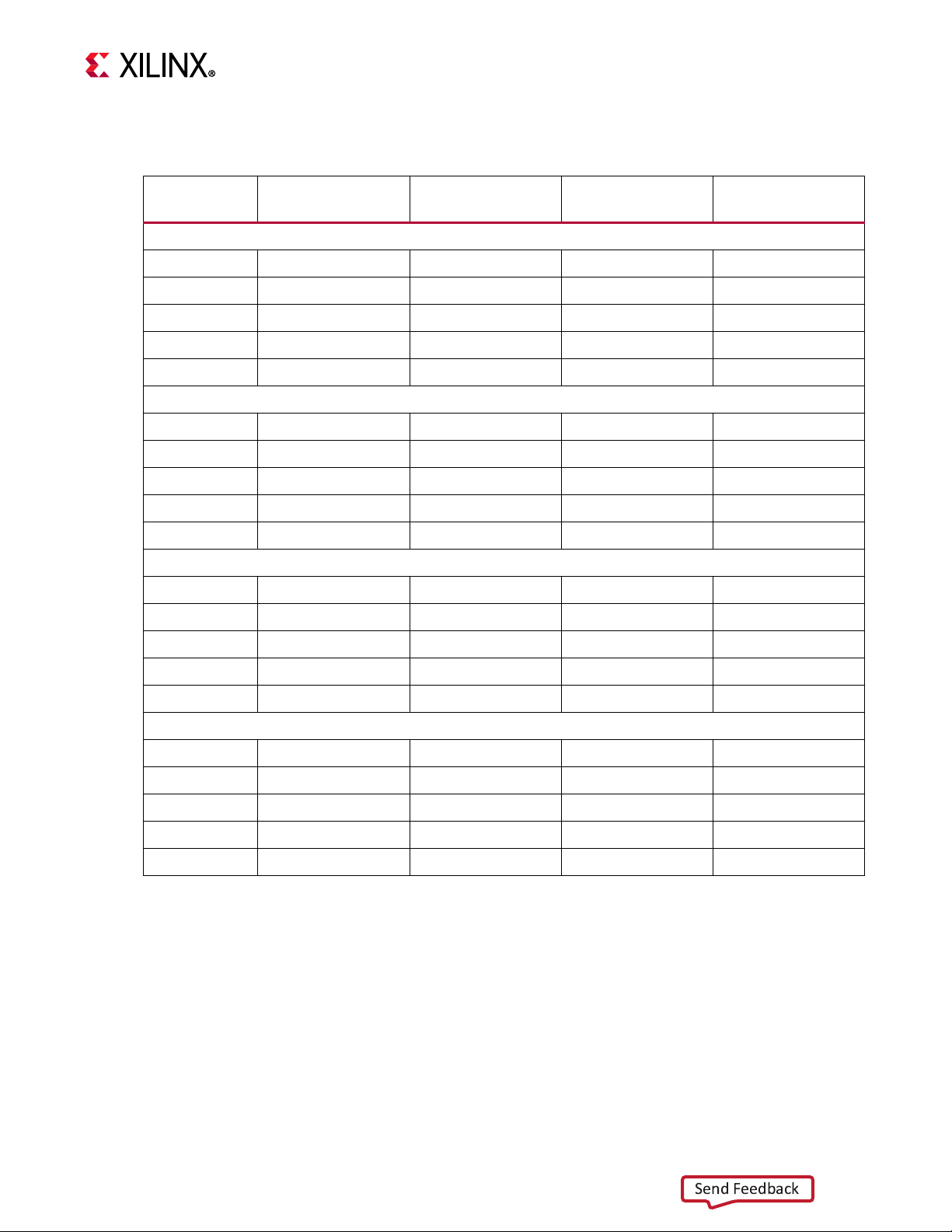
Chapter 3: Board Component Descriptions
Send Feedback
Tab l e 3- 22 lists the SFP28 module connections to the Zynq UltraScale+ RFSoC U1.
Table 3-22: SFP28 RFSoC Connections
XCZU28DR Pin
(U1)
Schematic Net
Name
I/O Standard SFP+ Pin SFP+ Pin Name
SFP0 J27
Y35 SFP0_TX_P
Y36 SFP0_TX_N
AA38 SFP0_RX_P
AA39 SFP0_RX_N
(1)
(1)
(1)
(1)
18 TD_P
19 TD_N
13 RD_P
12 RD_N
G12 SFP0_TX_DISABLE_B LVCMOS12 3 TX_DISABLE
SFP1 J32
V35 SFP1_TX_P
V36 SFP1_TX_N
W38 SFP1_RX_P
W39 SFP1_RX_N
(1)
(1)
(1)
(1)
18 TD_P
19 TD_N
13 RD_P
12 RD_N
G10 SFP0_TX_DISABLE_B LVCMOS12 3 TX_DISABLE
SFP2 J37
T35 SFP2_TX_P
T36 SFP2_TX_N
U38 SFP2_RX_P
U39 SFP2_RX_N
(1)
(1)
(1)
(1)
18 TD_P
19 TD_N
13 RD_P
12 RD_N
K12 SFP0_TX_DISABLE_B LVCMOS12 3 TX_DISABLE
SFP3 J42
R33 SFP3_TX_P
R34 SFP3_TX_N
R38 SFP3_RX_P
R39 SFP3_RX_N
(1)
(1)
(1)
(1)
18 TD_P
19 TD_N
13 RD_P
12 RD_N
J7 SFP0_TX_DISABLE_B LVCMOS12 3 TX_DISABLE
Notes:
1. Bank 128 GTY connections, I/O standards not applicable.
For additional information about the small form factor pluggable SFP28 module, see the
SFF-8402 and SFF-8432 specifications at the SNIA Technology Affiliates website [Ref 28].
ZCU111 Board User Guide 63
UG1271 (v1.1) August 6, 2018 www.xilinx.com
Page 64

X-Ref Target - Figure 3-24
X20492-062118
Send Feedback
Chapter 3: Board Component Descriptions
User PMOD GPIO Connectors
[Figure 2-1, callout 20, 21]
The ZCU111 evaluation board supports two right-angle PMOD GPIO receptacles J48 and
J49. The 3.3V PMOD nets are level-shifted and are wired to the XCZU28DR device U1 banks
28, 66, and 68. Figure 3-24 shows the GPIO PMOD connector circuits.
ZCU111 Board User Guide 64
UG1271 (v1.1) August 6, 2018 www.xilinx.com
Figure 3-24: PMOD Connectors
Page 65

Chapter 3: Board Component Descriptions
Send Feedback
Tab l e 3- 23 lists the connections between the XCZU28DR RFSoC and the PMOD
Table 3-23: PMOD Connections to XCZU28DR
XCZU28DR
(U1) Pin
C17 PMOD0_0 LVCMOS12 J48.1
M18 PMOD0_1 LVCMOS12 J48.3
H16 PMOD0_2 LVCMOS12 J48.5
H17 PMOD0_3 LVCMOS12 J48.7
J16 PMOD0_4 LVCMOS12 J48.2
K16 PMOD0_5 LVCMOS12 J48.4
H15 PMOD0_6 LVCMOS12 J48.6
J15 PMOD0_7 LVCMOS12 J48.8
L14 PMOD1_0 LVCMOS12 J49.1
L15 PMOD1_1 LVCMOS12 J49.3
M13 PMOD1_2 LVCMOS12 J49.5
N13 PMOD1_3 LVCMOS12 J49.7
M15 PMOD1_4 LVCMOS12 J49.2
N15 PMOD1_5 LVCMOS12 J49.4
M14 PMOD1_6 LVCMOS12 J49.6
Net Name
(1)
I/O Standard PMOD Pin
N14 PMOD1_7 LVCMOS12 J49.8
Notes:
1. Level-shifted net names at XCZU28DR have _LS appended.
For more information on the PMOD interface, see the Digilent website [Ref 27].
User I/O
[Figure 2-1, callouts 22-25]
The ZCU111 board provides these user and general purpose I/O capabilities:
• Eight user LEDs (callout 22)
GPIO_LED[7-0]: DS11, DS12, DS13, DS14, DS15, DS16, DS17, DS18
°
• 8-position user DIP Switch (callout 23)
GPIO_DIP_SW[7:0]: SW14
°
• Five user pushbuttons and CPU reset switch (callouts 24 and 25)
GPIO_SW_[NWCES]: SW9, SW10, SW11, SW12, SW13
°
CPU_RESET: SW15
°
ZCU111 Board User Guide 65
UG1271 (v1.1) August 6, 2018 www.xilinx.com
Page 66

X-Ref Target - Figure 3-25
X20493-062118
X20494-062118
Send Feedback
Chapter 3: Board Component Descriptions
Figure 3-25 through Figure 3-27 show the GPIO circuits. Table 3-24 lists the GPIO
connections to XCZU28DR U1 connections.
X-Ref Target - Figure 3-26
Figure 3-25: GPIO LEDs
Figure 3-26: GPIO 8-Pole DIP Switch
ZCU111 Board User Guide 66
UG1271 (v1.1) August 6, 2018 www.xilinx.com
Page 67

X-Ref Target - Figure 3-27
X20495-062118
Send Feedback
Chapter 3: Board Component Descriptions
Figure 3-27: GPIO Pushbutton Switches
Table 3-24: GPIO Connections to XCZU28DR
XCZU28DR (U1) Pin Net Name I/O Standard Device
GPIO LEDs (Active High)
AR13 GPIO_LED_0 LVCMOS18 DS11.2
AP13 GPIO_LED_1 LVCMOS18 DS12.2
AR16 GPIO_LED_2 LVCMOS18 DS13.2
AP16 GPIO_LED_3 LVCMOS18 DS14.2
AP15 GPIO_LED_4 LVCMOS18 DS15.2
AN16 GPIO_LED_5 LVCMOS18 DS16.2
AN17 GPIO_LED_6 LVCMOS18 DS17.2
AV15 GPIO_LED_7 LVCMOS18 DS18.2
GPIO DIP SW (Active High)
AF16 GPIO_DIP_SW0 LVCMOS18 SW14.8
(1)
ZCU111 Board User Guide 67
UG1271 (v1.1) August 6, 2018 www.xilinx.com
Page 68

Chapter 3: Board Component Descriptions
Send Feedback
Table 3-24: GPIO Connections to XCZU28DR (Cont’d)
XCZU28DR (U1) Pin Net Name I/O Standard Device
AF17 GPIO_DIP_SW1 LVCMOS18 SW14.7
AH15 GPIO_DIP_SW2 LVCMOS18 SW14.6
AH16 GPIO_DIP_SW3 LVCMOS18 SW14.5
AH17 GPIO_DIP_SW4 LVCMOS18 SW14.4
AG17 GPIO_DIP_SW5 LVCMOS18 SW14.3
AJ15 GPIO_DIP_SW6 LVCMOS18 SW14.2
AJ16 GPIO_DIP_SW7 LVCMOS18 SW14.1
Directional Pushbuttons (Active High)
AW3 GPIO_SW_N LVCMOS18 SW9.3
AW6 GPIO_SW_W LVCMOS18 SW10.3
AW5 GPIO_SW_C LVCMOS18 SW11.3
AW4 GPIO_SW_E LVCMOS18 SW12.3
E8 GPIO_SW_S LVCMOS18 SW13.3
CPU Reset Pushbutton (Active High)
AF15 CPU_RESET LVCMOS18 SW15.3
Notes:
1. Level-shifted net names at ZU28DR U1 have _LS appended.
ZCU111 Board User Guide 68
UG1271 (v1.1) August 6, 2018 www.xilinx.com
Page 69

Chapter 3: Board Component Descriptions
Send Feedback
Power and Status LEDs
[Figure 2-1, area of callout 22]
Tab l e 3- 25 defines the power and status LEDs. For user-controlled GPIO LED details, see
User I/O, page 65.
Table 3-25: Power and Status LEDs
Ref. Des. Schematic Net Name LED Color Description
DS1 PS_INIT_B Green/ Red
DS2 PS_DONE Green RFSoC U1 bit file download is complete.
DS3 PS_RESET_B Red
DS4 PS_ERR_OUT Red
DS5 PS_ERR_STATUS Red
DS6 PS_VCC3V3_PG Green DisplayPort 3.3V power on
DS7 USB3 MIC2544 U13 FLG Green PS USB 3.0 ULPI VBUS power error
DS27 ENET_LED_1 Green EHPY U37 1000BASE-T link is established.
DS47 MSP430_LED0 Green MSP430 U41 GPIO LED
DS46 MSP430_LED1 Green MSP430 U41 GPIO LED
DS11 GPIO_LED_7 Green USER GPIO LED
Green: FPGA initialization was successful.
Red: FPGA initialization is in progress.
POR U6 asserts RESET_B low when any of
the monit ored volt a ges ( IN_) falls belo w its
respective threshold, any EN_ goes low, or
MR is asserted.
PS error out is asserted for accidental loss
of power, an error in the PMU that holds
the CSU in reset, or an exception in the
PMU.
PS error s ta tus in di cat es a s ec ur e l ock do wn
state. Alternatively, it can be used by the
PMU firmware to indicate system status.
ZCU111 Board User Guide 69
UG1271 (v1.1) August 6, 2018 www.xilinx.com
DS12 GPIO_LED_6 Green USER GPIO LED
DS13 GPIO_LED_5 Green USER GPIO LED
DS14 GPIO_LED_4 Green USER GPIO LED
DS15 GPIO_LED_3 Green USER GPIO LED
DS16 GPIO_LED_2 Green USER GPIO LED
DS17 GPIO_LED_1 Green USER GPIO LED
DS18 GPIO_LED_0 Green USER GPIO LED
DS19 VCC12_SW Green 12VDC power on
DS20 VCCINT_PG Green VCCINT 0.85VDC power on
DS21 VCCPSINTFP_PG Green VCCPSINTFP 0.85VDC power on
DS22 VCC1V8 Green VCC1V8 1.8VDC power on
DS23 VCC1V2_PG Green VCC1V2 1.2VDC power on
Page 70

Chapter 3: Board Component Descriptions
Send Feedback
Table 3-25: Power and Status LEDs (Cont’d)
Ref. Des. Schematic Net Name LED Color Description
DS24 DAC_AVCC_PG Green ADC_AVCC 0.925V power on
DS25 VADJ_FMC_PG Green VADJ_FMC 1.8VDC (Nom.) power on
DS26 MGT1V2_PG Green MGT1V2 1.2VDC power on
DS43 MGTAVCC_PG Green MGTAVCC 0.9VDC power on
DS28 MGT1V8_PG Green MGT1V8 1.8VDC power on
DS29 MGTRAVCC_PG Green MGTRAVCC 0.85VDC power on
DS30 VCCINT_RF_PG Green VCCINT_RF 0.85VDC power on
DS31 ADC_AVCC_PG Green ADC_AVCC 0.925VDC power on
DS32 UTIL_3V5_PG Green UTIL_3V5 3.5VDC power on
DS33 ADC_AVCCAUX_PG Green ADC_AVCCAUX 1.8VDC power on
DS34 MUXOUT_RF1 Green LMX2594 U102 lock detect
DS35 MUXOUT_RF2 Green LMX2594 U103 lock detect
DS36 UTIL_1V13_PG Green UTIL_1V13 1.13VDC power on
DS37 UTIL_2V5_PG Green UTIL_2V5 2.5VDC power on
DS38 UTIL_3V3_PG Green UTIL_3V3 3.3VDC power on
DS39 UTIL_5V0_PG Green UTIL_5V0 5VDC power on
DS40 PS_DDR4_VTERM_0V60_PGOOD Green PS_DDR4_VTERM 0.6VDC power on
DS41 PL_DDR4_VTERM_0V60_PGOOD Green PL_DDR4_VTERM 0.6VDC power on
DS42 DAC_AVCCAUX_ON Green DAC_AVCCAUX 1.8VDC power on
DS44 MUXOUT_RF3 Green LMX2594 U104 lock detect
DS45 STATUS_4208 Green LMK04208 status
DS49 DAC_AVTT_PG Green DAC_AVTT 2.5VDC power on
DS8 RF_CLK_VCC3V3_PG Green RF_CLK_VCC3V3 3.3VDC power on
DS50 MIO23_LED Green RFSoC U1 bank 500 GPIO LED
ZCU111 Board User Guide 70
UG1271 (v1.1) August 6, 2018 www.xilinx.com
Page 71

Chapter 3: Board Component Descriptions
X20652-062118
Send Feedback
Figure 3-28 shows the power and status LEDs area of the board.
X-Ref Target - Figure 3-28
Figure 3-28: Power and Status LEDs
GTY Transceivers
[Figure 2-1, callout 1]
The XCZU28DR provides 16 GTY transceivers (32.75 Gb/s capable) on the PL-side.
The GTY transceivers in the XCZU28DR are grouped into four channels or quads. The
reference clock for a quad can be sourced from the quad above or the quad below the GTY
quad of interest. The four GTY quads used on the ZCU111 board have the connectivity listed
in this section.
• Quad 128:
• MGTREFCLK0 - SFP_SI5382_IN1_C_P/N
• MGTREFCLK1 - SFP_SI5382_OUT_C_P/N
• Contains four GTY transceivers allocated to SFP[0:3] TX/RX lanes
• Quad 129:
• MGTREFCLK0 - FMCP_HSPC_GBTCLK0_M2C_C_P/N
ZCU111 Board User Guide 71
UG1271 (v1.1) August 6, 2018 www.xilinx.com
• MGTREFCLK1 - USER_MGT_SI570_CLOCK_C_P/N
• Contains four GTY transceivers allocated to FMCP_HSPC_DP[0:3] TX/RX
• Quad 130:
• MGTREFCLK0 - FMCP_HSPC_GBTCLK1_M2C_C_P/N
Page 72

X-Ref Target - Figure 3-29
BANK 129
FMCP_HSPC_DP0
FMCP_HSPC_DP1
FMCP_HSPC_DP2
FMCP_HSPC_DP3
MGTY_129_0
MGTY_129_1
MGTY_129_2
MGTY_129_3
FMCP_HSPC_GBTCLK0_M2C
USER_MGT_S1570_CLOCK
MGT_129_REFCLK0
MGT_129_REFCLK1
BANK 131
FMCP_HSPC_DP8
FMCP_HSPC_DP9
FMCP_HSPC_DP10
FMCP_HSPC_DP11
MGTY_131_0
MGTY_131_1
MGTY_131_2
MGTY_131_3
FMCP_HSPC_GBTCLK2_M2C
NC
MGT_131_REFCLK0
MGT_131_REFCLK1
BANK 128
SFP0_TX/RX
SFP1_TX/RX
SFP2_TX/RX
SFP3_TX/RX
MGTY_128_0
MGTY_128_1
MGTY_128_2
MGTY_128_3
SFP_S15382_IN1
SFP_S15382_OUT
MGT_128_REFCLK0
MGT_128_REFCLK1
BANK 130
FMCP_HSPC_DP4
FMCP_HSPC_DP5
FMCP_HSPC_DP6
FMCP_HSPC_DP7
MGTY_130_0
MGTY_130_1
MGTY_130_2
MGTY_130_3
FMCP_HSPC_GBTCLK1_M2C
USER_SMA_MGT_CLOCK
MGT_130_REFCLK0
MGT_130_REFCLK1
X20536-071318
Send Feedback
Chapter 3: Board Component Descriptions
• MGTREFCLK1 - USER_SMA_MGT_CLOCK_C_P/N
• Contains four GTY transceivers allocated to FMCP_HSPC_DP[4:7] TX/RX
• Quad 131:
• MGTREFCLK0 - FMCP_HSPC_GBTCLK2_M2C_C_P/N
• MGTREFCLK1 - not connected
• Contains four GTY transceivers allocated to FMCP_HSPC_DP[8:11] TX/RX
Figure 3-29 shows the MGTY assignments.
ZCU111 Board User Guide 72
UG1271 (v1.1) August 6, 2018 www.xilinx.com
Figure 3-29: GTY Bank Assignments
FMCP HSPC
Twelve MGTs are provided by PL-side MGT banks 129, 130, and 131. Available MGT
reference clocks include the FMC defined GBT clocks 0, 1 and 2, a programmable SI570
clock and an SMA clock.
Page 73

Chapter 3: Board Component Descriptions
Send Feedback
SFP28
One PL-side GTY transceiver in bank 128 is provided for the quad SFP28 interface. Available
GTY reference clocks include a jitter attenuated recovered clock from a Si5382. SFP+
modules typically provide an I2C based control interface. This I2C interface is accessible for
each individual SFP28 module through the I2C multiplexer topology on the ZCU111 board.
The RFSoC U1 connections for each quad are referenced in Appendix B, Xilinx Design
Constraints.
For additional information on GTY transceivers, see the UltraScale Architecture GTY
Transceivers User Guide (UG578) [Ref 6].
PS-Side: GTR Transceivers
[Figure 2-1, callout 1]
The PS-side GTR transceiver bank 505 supports two DisplayPort transmit channels, USB (3.0)
and SATA, as shown in Figure 3-30.
ZCU111 Board User Guide 73
UG1271 (v1.1) August 6, 2018 www.xilinx.com
Page 74

X-Ref Target - Figure 3-30
X20565-062118
Send Feedback
Chapter 3: Board Component Descriptions
ZCU111 Board User Guide 74
UG1271 (v1.1) August 6, 2018 www.xilinx.com
Figure 3-30: PS-GTR Lane Assignments
Bank 505 DP (DisplayPort) lanes 0 and 1 TX support the 2-channel source only PS-side
DisplayPort circuitry described in DPAUX (MIO 27-30), page 35.
Bank 505 USB0 lane 2 supports the USB3.0 interface described in USB 3.0 Transceiver and
USB 2.0 ULPI PHY, page 39.
Bank 505 SATA1 lane 3 supports the M.2 SATA connector U170 as shown in Figure 3-31.
Bank 505 reference clocks are connected to the U46 SI5341B clock generator as detailed in
SI5341B 10 Independent Output Any-Frequency Clock Generator, page 47.
Bank 505 connections are referenced in Appendix B, Xilinx Design Constraints.
Page 75

X-Ref Target - Figure 3-31
X20566-062118
Send Feedback
Chapter 3: Board Component Descriptions
PS M.2 SATA Connector
[Figure 2-1, callout 34]
The M.2 SATA interface is provided for SATA SSD access using the PS-side bank 505 GTR
transceiver. Figure 3-31 shows M.2 connector U40.
The socket 2 SATA adapter pinout with key M is shown in Tab le 3-2 6. SATA-A data
connection is used for TX and SATA-B for RX. The M.2 connector U40 is a type 2242 (active
component section 22 mm wide with overall length 42 mm form factor) used on socket 2.
ZCU111 Board User Guide 75
UG1271 (v1.1) August 6, 2018 www.xilinx.com
Figure 3-31: M.2 Connector U170
Page 76

Table 3-26: M.2 Connector U40 Pinout
Send Feedback
Pin Signal
74 3.3V
72 3.3V
70 3.3V
68 SUSCLK(32 kHz) (I)(0/3.3V)
58 Reserved for MGFG_CLOCK
56 Reserved for MGFG_DATA
54 NC
52 NC
50 NC
Chapter 3: Board Component Descriptions
ADD_IN CARD KEY M
ADD_IN CARD KEY M
ADD_IN CARD KEY M
ADD_IN CARD KEY M
48 NC
46 NC
44 ALERT# (O) (0/1.8V)
42 SMB_DATA (I/O) (0/1.8V)
40 SMB_CLK (I/O) (0/1.8V)
38 DEVSLP (I)
36 NC
34 NC
32 NC
30 NC
28 NC
26 NC
24 NC
22 NC
20 NC
18 3.3V
16 3.3V
ZCU111 Board User Guide 76
UG1271 (v1.1) August 6, 2018 www.xilinx.com
14 3.3V
12 3.3V
10 DAS/DSS (I/O)
8NC
6NC
Page 77

Table 3-26: M.2 Connector U40 Pinout (Cont’d)
Send Feedback
Pin Signal
43.3V
23.3V
75 GND
73 GND
71 GND
69 PEDET (GND-SATA)
67 NC
57 GND
55 NC
Chapter 3: Board Component Descriptions
ADD_IN CARD KEY M
ADD_IN CARD KEY M
ADD_IN CARD KEY M
ADD_IN CARD KEY M
53 NC
51 GND
49 SATA-A+
47 SATA-A-
45 GND
43 SATA-B+
41 SATA-B-
39 GND
37 NC
35 NC
33 GND
31 NC
29 NC
27 GND
25 NC
23 NC
21 GND
ZCU111 Board User Guide 77
UG1271 (v1.1) August 6, 2018 www.xilinx.com
19 NC
17 NC
15 GND
13 NC
11 NC
Page 78

Chapter 3: Board Component Descriptions
Send Feedback
Table 3-26: M.2 Connector U40 Pinout (Cont’d)
Pin Signal
9GND
7NC
5NC
3GND
1GND
The M.2 adapter tie-offs as implemented on the ZCU111 board are listed in Ta ble 3 -27.
Table 3-27: M.2 U40 Connector Tie-offs
M.2 Signal Name ZCU111 Tie-Off U40 Pin
SUSCLK No connect 68
ALERT# No connect 44
SMB_DATA No connect 42
SMB_CLK No connect 40
DEVSLP GND 38
DAS/DSS DNP Res to GND 10
PEDET No connect 69
SATA-A GTR TX 49, 47
SATA-B GTR RX 43, 41
The M.2 U40 connector to RFSoC connections are listed in Tab l e 3- 2 8.
Table 3-28: M.2 U40 Connections to the XCZU28DR RFSoC
XCZU28DR
(U1) Pin
AD36 GT3_SATA1_TX_P (1) 49 SATA-A+
AD37 GT3_SATA1_TX_N (1) 47 SATA-A-
AC38 GT3_SATA1_RX_P (1) 41 SATA-B+
AC39 GT3_SATA1_RX_N (1) 43 SATA-B-
Notes:
1. Series capacitor coupled, MGT I/F, I/O standards do not apply.
Net Name I/O Standard
M.2 Connector U40
Pin Number Pin Name
For more information, see PCI_Express_M.2_Specification_Rev1.1_TS_12092016_NCB
[Ref 21].
ZCU111 Board User Guide 78
UG1271 (v1.1) August 6, 2018 www.xilinx.com
Page 79

Chapter 3: Board Component Descriptions
Send Feedback
FPGA Mezzanine Card Interface
[Figure 2-1, callouts 33,34]
The ZCU111 evaluation board supports the VITA 57.4 FPGA mezzanine card (FMC+ or
FMCP) specification by providing a subset implementation of the high pin count connector
at J26 (HSPC). FMC+ connectors use a 14 x 40 form factor, populated with 560 pins. The
connector is keyed so that a mezzanine card, when installed on the ZCU111 evaluation
board, faces away from the board
J26 FMC+ Connector Type
• Samtec SEAF series, 1.27 mm (0.050 in) pitch. Mates with SEAM series connector. For
more information about SEAF series connectors, see the Samtec website [Ref 22]. For
more information about the VITA 57.4 FMC+ specification, see the VITA FMC Marketing
Alliance website [Ref 23].
• The 560-pin FMC+ connector defined by the FMC specification (see Appendix A, VITA
57.4 FMCP Connector Pinouts) provides connectivity for up to:
160 single-ended or 80 differential user-defined signals
°
24 transceiver differential pairs
°
6 transceiver differential clocks
°
4 differential clocks
°
239 ground and 19 power connections
°
FMCP Connector J26
[Figure 2-1, callout 27]
The HSPC connector J26 implements a subset of the full FMCP connectivity:
• 68 single-ended or 34 differential user-defined pairs (34 LA pairs: LA[00:33])
• 12 transceiver differential pairs
• 3 transceiver differential clocks
• 2 differential clocks
• 239 ground and 16 power connections
ZCU111 Board User Guide 79
UG1271 (v1.1) August 6, 2018 www.xilinx.com
The FMCP HSPC J26 connections to RFSoC U1 are referenced in Appendix B, Xilinx Design
Constraints. See the FPGA Mezzanine Card (FMC) VITA 57.4 specification [Ref 23] for
additional information on the FMCP HSPC connector.
Page 80

Chapter 3: Board Component Descriptions
X20570-062118
Send Feedback
Cooling Fan Connector
[Figure 2-1, near callout 10]
The ZCU111 cooling fan connector is shown in Figure 3-32.
The ZCU111 uses the Infineon MAX6643 (U52) fan controller, which autonomously controls
the fan speed by controlling the pulse width modulation (PWM) signal to the fan based on
the die temperature sensed via the FPGA's DXP and DXN pins. The fan rotates slowly
(acoustically quiet) when the RFSoC is cool and rotates faster as the FPGA heats up
(acoustically noisy).
The fan speed (PWM) versus the RFSoC die temperature algorithm along with the over
temperature set point and fan failure alarm mechanisms are defined by the strapping
resistors on the MAX6643 device. The over temperature and fan failures alarms can be
monitored by any available processor in the RFSoC by polling the I2C expander U22 on the
I2C0 bus. See the MAX6643 [Ref 24] data sheet for more information on the device circuit
implementation on this board.
X-Ref Target - Figure 3-32
Note:
seconds.
At initial power on, it is normal for the fan controller to energize at full speed for a few
Figure 3-32: 12V Fan Header
VADJ_FMC Power Rail
The ZCU111 evaluation board implements the ANSI/VITA 57.4 IPMI support functionality.
The power control of the VADJ_FMC power rail is managed by the U42 system controller.
This rail powers the FMCP HSPC (J26) VADJ pins, as well as the XCZU28DR HP banks 65, 66.
The valid values of the VADJ_FMC rail are 1.2V, 1.5V, and 1.8V.
ZCU111 Board User Guide 80
UG1271 (v1.1) August 6, 2018 www.xilinx.com
At power on, the system controller detects if an FMC module is installed on J26:
• If no card is attached to the FMCP connector, the VADJ voltage is set to 1.8V
Page 81

Chapter 3: Board Component Descriptions
Send Feedback
• When an FMC card is attached, its IIC EEPROM is read to find a VADJ voltage supported
by both the ZCU111 board and the FMC module, within the available choices of 1.8V,
1.5V, 1.2V, and 0.0V
• If no valid information is found in an FMC card IIC EEPROM, the VADJ_FMC rail is set to
0.0V
The system controller user interface allows the FMC IPMI routine to be overridden and an
explicit value can be set for the VADJ_FMC rail. Override mode is useful for FMC mezzanine
cards that do not contain valid IPMI EPROM data defined by the ANSI/VITA57.1
specification.
ZCU111 System Controller
[Figure 2-1, callout 19]
The ZCU111 board includes an on-board system controller. A host PC resident system
controller user interface (SCUI) is provided on the ZCU111 Evaluation Kit website. This GUI
enables the query and control of select programmable features such as clocks, FMC
functionality, and power system parameters. The ZCU111 web page also includes a tutorial
on the SCUI (XTP517) [Ref 11] and board setup instructions (XTP518) [Ref 12].
A brief summary of these instructions are provided here:
1. Ensure that the Silicon Labs VCP USB-UART drivers are installed. See the Silicon Labs
CP210x USB-to-UART Installation Guide (UG1033) [Ref 14].
2. Download the SCUI host PC application.
3. Connect the micro-USB to ZCU111 USB-UART connector (J83).
4. Power-cycle the ZCU111.
5. Launch the SCUI.
The SCUI GUI is shown in Figure 3-33.
ZCU111 Board User Guide 81
UG1271 (v1.1) August 6, 2018 www.xilinx.com
Page 82

X-Ref Target - Figure 3-33
X20571-062118
Send Feedback
Chapter 3: Board Component Descriptions
ZCU111 Board User Guide 82
UG1271 (v1.1) August 6, 2018 www.xilinx.com
Figure 3-33: System Controller User Interface
Page 83

Chapter 3: Board Component Descriptions
Send Feedback
On first use of the SCUI, go to the FMC > Set VADJ > Boot-up tab and click USE FMC
EEPROM Voltage. The SCUI buttons gray-out during command execution and return to
their original appearance when ready to accept a new command.
See the System Controller Tutorial (XTP517) [Ref 11] and the ZCU111 Software Install and
Board Setup Tutorial (XTP518) [Ref 12] for more information on installing and using the
system controller utility.
Switches
[Figure 2-1, callouts 27, 29, 31, and 46]
The ZCU111 board includes power, configuration, and reset switches:
• SW1 power on/off slide switch (callout 29)
•SW2 (PS_PROG_B), active-Low pushbutton (callout 31)
• SW3 (SRST_B), active-Low pushbutton (callout 27)
•SW4 (POR_B), active-Low pushbutton (callout 27)
• SW6 U1 RFSoC PS bank 503 4-pole mode DIP switch (callout 32)
Power On/Off Slide Switch
[Figure 2-1, callout 29]
The ZCU111 board power switch is SW1. Sliding the switch actuator from the off to on
position applies 12V power from J52, a 6-pin mini-fit connector. Green LED DS19
illuminates when the ZCU111 board power is on. See Board Power System for details on the
on-board power system.
CAUTION! Do NOT plug a PC ATX power supply 6-pin connector into the ZCU111 board power
connector J52. The ATX 6-pin connector has a different pin-out than J52. Connecting an ATX 6-pin
connector into J52 damages the ZCU111 board and voids the board warranty.
ZCU111 Board User Guide 83
UG1271 (v1.1) August 6, 2018 www.xilinx.com
Page 84

X-Ref Target - Figure 3-34
X20572-062118
X20573-062118
Send Feedback
Chapter 3: Board Component Descriptions
Figure 3-34 shows the power connector J52, power switch SW16, and LED indicator DS19.
Figure 3-34: Power Input
Program_B Pushbutton
[Figure 2-1, callout 31]
PS_PROG_B pushbutton switch SW2 grounds the XCZU28DR RFSoC PS_PROG_B pin AA27
when pressed (see Figure 3-35). This action clears the programmable logic configuration,
which can then be acted on by the PS software. See the Zynq UltraScale+ Device Technical
Reference Manual (UG1085) [Ref 3] for information about Zynq UltraScale+ RFSoC
configuration.
X-Ref Target - Figure 3-35
ZCU111 Board User Guide 84
UG1271 (v1.1) August 6, 2018 www.xilinx.com
Figure 3-35: PS_PROG_B Pushbutton Switch
Page 85

X-Ref Target - Figure 3-36
X20574-062118
Send Feedback
Chapter 3: Board Component Descriptions
System Reset Pushbuttons
[Figure 2-1, callout 54]
Figure 3-36 shows the reset circuitry for the PS.
ZCU111 Board User Guide 85
UG1271 (v1.1) August 6, 2018 www.xilinx.com
Figure 3-36: PS SRST_B and POR_B Pushbutton Switches SW3 and SW4
PS_POR_B Reset
Depressing and then releasing pushbutton SW4 causes net PS_POR_B to strobe Low. This
reset is used to hold the PS in reset until all PS power supplies are at the required voltage
levels. It must be held Low through PS power-up. PS_POR_B should be generated by the
power supply power-good signal. When the voltage at IN1 is below its threshold or EN1
(P.B. switch SW4 is pressed) goes Low, OUT1 (PS_POR_B) goes Low.
Page 86

Chapter 3: Board Component Descriptions
Send Feedback
PS_SRST_B Reset
Depressing and then releasing pushbutton SW3 causes net PS_SRST_B to strobe Low. This
reset is used to force a system reset. It can be tied or pulled High, and can be High during
the PS supply power ramps. When the voltage at IN2 is below its threshold or EN2 (P.B.
switch SW3 is pressed) goes Low, OUT2 (PS_SRST_B) goes Low.
Active-Low reset output RST_B asserts when any of the monitored voltages (IN_) falls below
the respective threshold, any EN_ goes Low, or MR is asserted. RST_B remains asserted for
the reset time-out period after all of the monitored voltages exceed their respective
threshold, all EN_ are High, all OUT_ are High, and MR is deasserted. See the Zynq
UltraScale+ Device Technical Reference Manual (UG1085) [Ref 3] for information on the
resets.
Board Power System
[Figure 2-15, callout 35]
The ZCU111 evaluation board uses power management ICs (PMIC) and power regulators
from Infineon [Ref 25] to supply the core and auxiliary voltages listed in Table 3-29 . See
schematic 0381811.
Table 3-29: Power System Devices
Ref Des,
PMBus
ADDR
U 5 3
(0X43)
U 5 5
(0X44)
C on t ro ll er
or
Regulator
IRPS5401_A VCCINT_IO_BRAM_PS_SDFEC 0.85 10 U59 0x41
IRPS5401_B VCC1V8 1.8 2 U61 0x42
IRPS5401_C VCCINT_RF 0.85 7 U63 0x49
IRPS5401_D Tied to chan. C
IRPS5401_LDO N.C.
IRPS5401_A UTIL_3V3 3.3 10.5
IRPS5401_B UTIL_2V5 2.5 2
IRPS5401_C MGT1V2 1.2 6 U66 0x47
IRPS5401_D Tied to chan. C
IRPS5401_LDO MGTRAVCC 0.85 0.5 DVM on R399
Rail Name
Voltage
(V)
Max
Current
(A)
INA226
Sensor
INA226
PMBus
ADDR
Sense
Resistor
(Ω)
R394:
0.005
R388:
0.005
R389:
0.005
R398:
0.005
R399:
0.005
0381811
Schem.
Page
47
49
ZCU111 Board User Guide 86
UG1271 (v1.1) August 6, 2018 www.xilinx.com
Page 87

Table 3-29: Power System Devices (Cont’d)
Send Feedback
Chapter 3: Board Component Descriptions
Ref Des,
PMBus
ADDR
U 5 7
(0X45)
U68 IR38064 VCCINT 0.85 30 U67 0x40
U70 IR38060 MGTAVCC 0.9 3 U69 0x46
U72 IFX1763 DAC_AVCCAUX 1.8 0.5 U71 0x4B
U74 IR38060 ADC_AVCCAUX 1.8 2 U73 0x4D
U75 IR38060 UTIL_1V13 1.13 4 58
C on t ro ll er
or
Rail Name
Regulator
IRPS5401_A VCC1V2 1.2 6 U60 0x43
IRPS5401_B DAC_AVTT 2.5/3.0 0.5 U3 0x4A
IRPS5401_C VADJ_FMC 1.8 5 U64 0x45
IRPS5401_D Tied to 3C
IRPS5401_LDO MGT1V8 1.8 0.5 U65 0x48
Voltage
(V)
Max
Current
(A)
INA226
Sensor
INA226
PMBus
ADDR
Resistor
Sense
(Ω)
R418:
0.005
R409:
0.005
R412:
0.005
R413:
0.005
R447:
0.002
R456:
0.002
R463:
0.005
R471:
0.005
0381811
Schem.
Page
51
54
55
56
57
U76 IR3883 UTIL_5V0 5 2.7 59
U101 ISL80112 ADC_AVCC 0.925 2 U77 0x4C
U78 ISL80112 DAC_AVCC 0.925 1 U79 0x4E
U81 IR3897 PL_DDR4_VTT 0.6 ±3.0 61
U82 IR3897 PS_DDR4_VTT 0.6 ±3.0 61
R489:
0.005
R494:
0.005
60
60
The FMCP HSPC (J26) and VADJ pins are wired to the programmable rail VADJ_FMC. The
VADJ_FMC rail is programmed to 1.80V by default. The VADJ_FMC rail also powers the
XCZU28DR HP banks 65 and 66 (see Ta bl e 3 - 1). Documentation describing PMBus
programming for the Infineon power controllers is available at the Infineon website
[Ref 25]. The PCB layout and power system design meets the recommended criteria
described in the UltraScale Architecture PCB Design User Guide (UG583) [Ref 4].
ZCU111 Board User Guide 87
UG1271 (v1.1) August 6, 2018 www.xilinx.com
Page 88

Chapter 3: Board Component Descriptions
Send Feedback
Monitoring Voltage and Current
Voltage and current monitoring and control are available for the Infineon power system
controllers through the Infineon PowIRCenter graphical user interface. The PMBus interface
controllers and regulators listed in Ta bl e 3 - 29 are accessed through the 1x3 PMBus
connector J19, which is provided for use with the Infineon PowIRCenter USB cable (Infineon
part number USB005) and can be ordered from the Infineon website [Ref 25]. The
associated Infineon PowerTool GUI can be downloaded from the Infineon website. This is
the simplest and most convenient way to monitor the voltage and current values for the
Infineon PMBus programmed power rails listed in Tab le 3- 2 9.
Each Infineon PMIC controller can report the voltage and current of its controlled rail to the
Infineon GUI for display to the user. Fourteen rails have a TI INA226 PMBus power monitor
circuit with connections to the rail series current sense resistor. This arrangement permits
the INA226 to report the sensed parameters separately on the PMBus. The rails configured
with the INA226 power monitors are shown in Ta b le 3 - 29.
As described in I2C0 (MIO 14-15), page 29, the I2C0 bus provides access to the PMBus
power controllers and the INA226 power monitors via the U23 PCA9544A bus switch. All
PMBus controlled Infineon regulators are tied to the IRPS5401_SDA/SCL PMBUS, while the
INA226 power monitors are separated on to INA226_PMBUS.
Figure 3-3, page 29 and Table 3-5, page 31 document the I2C0 bus access path to the
Infineon PMBus controllers and INA226 power monitor op amps. Also, see schematic
0381881. Power rail measurements are accessible to the system controller and RFSoC PL
logic through their respective I2C0 bus connections.
ZCU111 Board User Guide 88
UG1271 (v1.1) August 6, 2018 www.xilinx.com
Page 89

Appendix A
X20518-062118
Send Feedback
VITA 57.4 FMCP Connector Pinouts
Overview
Figure A-1 shows the pinout of the FPGA plus mezzanine card (FMCP) high pin count
(HSPC) connector defined by the VITA 57.4 FMC specification. For a description of how the
ZCU111 evaluation board implements the FMCP specification, see FPGA Mezzanine Card
Interface, page 79.
X-Ref Target - Figure A-1
ZCU111 Board User Guide 89
UG1271 (v1.1) August 6, 2018 www.xilinx.com
Figure A-1: FMCP HSPC Connector Pinout
Page 90

Xilinx Design Constraints
Send Feedback
Overview
The Xilinx design constraints (XDC) file template for the ZCU111 board provides for designs
targeting the ZCU111 evaluation board. Net names in the constraints listed correlate with
net names on the latest ZCU111 evaluation board schematic. Identify the appropriate pins
and replace the net names with net names in the user RTL. See the Vivado Design Suite User
Guide: Using Constraints (UG903) [Ref 8] for more information.
The HSPC FMCP connector J26 is connected to RFSoC banks powered by the variable
voltage V
I/O standards must be uniquely defined by each customer.
AJ_FMC
. Because different FMC cards implement different circuitry, the FMC bank
Appendix B
IMPORTANT: See ZCU111 board documentation for the XDC file.
ZCU111 Board User Guide 90
UG1271 (v1.1) August 6, 2018 www.xilinx.com
Page 91

Appendix C
Send Feedback
Regulatory and Compliance Information
Overview
This product is designed and tested to conform to the European Union directives and
standards described in this section.
ZCU111 Evaluation Kit — Master Answer Record 70958
For Technical Support, open a Support Service Request.
CE Directives
2006/95/EC, Low Voltage Directive (LVD)
2004/108/EC, Electromagnetic Compatibility (EMC) Directive
CE Standards
EN standards are maintained by the European Committee for Electrotechnical
Standardization (CENELEC). IEC standards are maintained by the International
Electrotechnical Commission (IEC).
Electromagnetic Compatibility
EN 55022:2010, Information Technology Equipment Radio Disturbance Characteristics –
Limits and Methods of Measurement
EN 55024:2010, Information Technology Equipment Immunity Characteristics – Limits and
Methods of Measurement
This is a Class A product. In a domestic environment, this product can cause radio
interference, in which case the user might be required to take adequate measures.
ZCU111 Board User Guide 91
UG1271 (v1.1) August 6, 2018 www.xilinx.com
Page 92

Appendix C: Regulatory and Compliance Information
Send Feedback
Safety
IEC 60950-1:2005, Information technology equipment – Safety, Part 1: General requirements
EN 60950-1:2006, Information technology equipment – Safety, Part 1: General requirements
Markings
This product complies with Directive 2002/96/EC on waste electrical and
electronic equipment (WEEE). The affixed product label indicates that the user
must not discard this electrical or electronic product in domestic household
waste.
This product complies with Directive 2002/95/EC on the restriction of hazardous
substances (RoHS) in electrical and electronic equipment.
This product complies with CE Directives 2006/95/EC, Low Voltage Directive (LVD)
and 2004/108/EC, Electromagnetic Compatibility (EMC) Directive.
ZCU111 Board User Guide 92
UG1271 (v1.1) August 6, 2018 www.xilinx.com
Page 93

HW-FMC-XM500
Send Feedback
Overview
The ZU28DRF-FFVG1517 contains eight multi-gigasample (4 GSPS), 12-bit RF
analog-to-digital converter (RF-ADC) channels across four banks and eight
multi-gigasample (6.544 GSPS), 14-bit RF digital-to-analog (RF-DAC) converter channels
across two banks. The ZCU111 board provides a pair of Samtec LPAF connectors for the
RF-ADC/RF-DAC clock and RF signals. The FMC-XM500 is an out-of-the-box AMS RFMC
plug-in card that mates with the ZCU111 board via two Samtec LPAM (8x40) connectors on
the bottom of the XM500 card with connectivity featuring:
• Two DACs and two ADCs routed to HF baluns with –1dB Pi pad attenuators and then to
SMAs
Appendix D
• Two DACs and two ADCs routed to LF baluns with –3dB Pi pad attenuators and then to
SMAs
• Four DACs and four ADCs routed to SMAs for use with external custom baluns and
filters
• Four pairs external input clocks for ADCs
• Four pairs external input clocks for DACs
ZCU111 Board User Guide 93
UG1271 (v1.1) August 6, 2018 www.xilinx.com
Page 94

X-Ref Target - Figure D-1
NO OF
ROWS
B
-04
(8.18)
.322
-06
(10.72)
.422
-08
(13.26)
.522
LEAD STYLE A
-01.0
(3.68)
.145
-01.5
(4.19)
.165
B
(1,27) .050
No. of positions x
(1,27) .050 + (6,76) .266
(1,27)
.050
(1,27)
.050
(1,32) .052 DIA
No. of positions x
(1,27) .050 + (3,10) .122
A
X21080-062118
Send Feedback
Appendix D: HW-FMC-XM500
AMS RFMC Plug-in Card Interface
On the bottom of the XM500 card, two Samtec LPAM (8x40) terminals provide access to the
ADC/DAC clocking and data path signals. The Samtec part number is
LPAM-40-010-S-08-2-K-TR. Figure D-1 shows the Samtec LPAM connector.
ZCU111 Board User Guide 94
UG1271 (v1.1) August 6, 2018 www.xilinx.com
Figure D-1: Samtec LPAM Connector
Page 95

X-Ref Target - Figure D-2
X21081-062118
Send Feedback
Appendix D: HW-FMC-XM500
XM500 Card Components
The XM500 card component locations are shown in Figure D-2 and listed in Tab l e D- 1 .
ZCU111 Board User Guide 95
UG1271 (v1.1) August 6, 2018 www.xilinx.com
Figure D-2: XM500 Card Components
Page 96

Table D-1: XM500 Card Components Locations
Send Feedback
Appendix D: HW-FMC-XM500
Callout
No.
1 J333
2 J888
3 MH15,16,17
4 U8, U9, J3, J4
5 U6, U7, J1, J2
6 U1, U3, J7, J8
7 U4, U5, J5, J6
8 J32-J37, J39, J40 Four channels ADCs to SMAs
9
Ref Des. Feature Notes
ADC connector,
low profile array (LPAM) terminal
DAC connector,
low profile array (LPAM) terminal
Mounting holes for the jackscrew of
LPAF connector mounting system
Two channels ADC Low frequency
baluns with -3dB attenuators to SMAs
Two channels ADC High frequency
baluns with -1dB attenuators to SMAs
Two channels DAC High frequency
baluns with -1dB attenuators to SMAs
Two channels DAC Low frequency
baluns with -3dB attenuators to SMAs
J30, J31, J891-J894,
J889, J890
Four pairs external input clock SMAs
for ADC
Schematic
0381858
Page
Samtec
LPAM-40-010-S-08-2-K-TR
Samtec
LPAM-40-010-S-08-2-K-TR
Jackscrew attached with
ZCU111 board
Mini-Circuits TCM2-33WX+ 2
Anaren BD1631J50100AHF 2
Anaren BD1631J50100AHF 2
Mini-Circuits TCM2-33WX+ 2
Molex Screw-on SMA:
0732513481
Molex Screw-on SMA:
0732513481
3
4
2
3
3
10 J28, J29, J895-J900
11 J20-J27 Four channels DACs to SMAs
12 J10 20 ADC I/Os to 2x10 header 2.54mm 2x10 header 3
13 J9 20 DAC I/Os to 2x10 header 2.54mm 2x10 header 4
14 MH11-MH14 Mounting holes for standoff
Four pairs external input clock SMAs
for DAC
Molex Screw-on SMA:
0732513481
Molex Screw-on SMA:
0732513481
#4-40 0.625" alum standoffs
(5/8" or 15.9mm)
4
4
2
ZCU111 Board User Guide 96
UG1271 (v1.1) August 6, 2018 www.xilinx.com
Page 97

X-Ref Target - Figure D-3
FPGA
ADC_00
ADC_01
ADC_02
ADC_03
ADC_04
ADC_05
ADC_06
ADC_07
AMC
DAC_00
DAC_01
DAC_02
DAC_03
DAC_04
DAC_05
DAC_06
DAC_07
224
0
2
1
3
225
0
2
1
3
226
0
2
1
3
227
0
2
1
3
224
01
23
225
01
23
226
01
23
227
01
23
228
0
2
1
3
229
0
2
1
3
230
0
2
1
3
231
0
2
1
3
228
0
1
2
3
0
1
229
2
3
X21082-062118
Send Feedback
Appendix D: HW-FMC-XM500
ADC/DAC Bank Data and Clock Channel Mapping
This section provides details on the ZCU111 boar d U1 RFSoC ZCU28DR ADC/DAC bank data
and clock channel mapping. Figure D-3 and Figure D-4 show the ZCU111 board U1 RFSoC
ZC28DR bank RF channel mapping and RF bank connectivity.
ZCU111 Board User Guide 97
UG1271 (v1.1) August 6, 2018 www.xilinx.com
Figure D-3: RFSoC ZCU28DR ADC/DAC Bank Channel Mapping
Page 98

X-Ref Target - Figure D-4
X21086-062018
Send Feedback
Appendix D: HW-FMC-XM500
ZCU111 Board User Guide 98
UG1271 (v1.1) August 6, 2018 www.xilinx.com
Figure D-4: RFSoC ZCU28DR ADC/DAC Banks 224-229 Connectivity
Page 99

Appendix D: HW-FMC-XM500
Send Feedback
XM500 ADC/DAC Data and Clock SMA
This section provides details on the XM500 ADC/DAC data and clock SMA, and I/O 2x10
header connectors to the ZCU111 board U1 RFSoC ZCU28DR channel mapping. Tab le D-2
provides the XM500 ADC/DAC data and clock mapping.
Table D-2: XM500 ADC/DAC Data and Clock Mapping
SMA Ref. Des. ADC/DAC Data or Clock
J26(P)/J27(N) DAC228_T0_Ch0
J20(P)/J21(N) DAC228_T0_Ch1
J22(P)/J23(N) DAC228_T0_Ch2
J24(P)/J25(N) DAC228_T0_Ch3
J7 DAC229_T1_Ch0
J8 DAC229_T1_Ch1
J5 DAC229_T1_Ch2
J6 DAC229_T1_Ch3
J4 ADC224_T0_Ch0
J3 ADC224_T0_Ch1
J2 ADC225_T1_Ch0
J1 ADC225_T1_Ch1
J33(P)/J32(N) ADC226_T2_Ch0
J34(P)/J35(N) ADC226_T2_Ch1
J37(P)/J36(N) ADC227_T3_Ch0
J39(P)/J40(N) ADC227_T3_Ch1
J30(P)/J31(N) ADC224_T0_CLKIN
J889(P)/J890(N) ADC225_T1_CLKIN
J891(P)/J892(N) ADC226_T2_CLKIN
J893(P)/J894(N) ADC227_T3_CLKIN
J28(P)/J29(N) DAC228_T0_CLKIN
J896(P)/J895(N) DAC229_T1_CLKIN
J898(P)/J897(N) DAC230_T2_CLKIN
J900(P)/J899(N) DAC231_T3_CLKIN
ZCU111 Board User Guide 99
UG1271 (v1.1) August 6, 2018 www.xilinx.com
J9 2x10 header See Figure D-5
J10 2x10 header See Figure D-5
Page 100

X-Ref Target - Figure D-5
X21087-062018
Send Feedback
Appendix D: HW-FMC-XM500
Figure D-5 shows the XM500 2x10 header connector J10 ADCIO and J9 DACIO to the
ZCU111 board U1 RFSoC ZC28DR bank 84 and 87 mapping.
ZCU111 Board User Guide 100
UG1271 (v1.1) August 6, 2018 www.xilinx.com
Figure D-5: XM500 J10, J9 2x10 Header to ZCU111 Board U1 RFSoC ZCU28DR
ADC/DAC Banks 84, 87 Connectivity
 Loading...