

Page 1
ZC702 Si570 Programming
November 2014
XTP181
Page 2
Revision History
Date Version Description
11/24/14 12.0 Recompiled for 2014.4.
10/08/14 11.0 Recompiled for 2014.3.
06/09/14 10.0 Recompiled for 2014.2.
04/16/14 9.0 Recompiled for 2014.1.
12/18/13 8.0 Recompiled for 2013.4.
10/23/13 7.0 Recompiled for 2013.3.
06/19/13 6.0 Recompiled for Vivado 2013.2.
04/03/13 5.0 Recompiled for 14.5.
12/18/12 4.0 Recompiled for 14.4.
10/23/12 3.0 Recompiled for 14.3. Added AR52580.
07/25/12 2.0 Recompiled for 14.2. Added AR47530.
05/25/12 1.0 Initial version for 14.1.
© Copyright 2014 Xilinx, Inc. All Rights Reserved.
XILINX, the Xilinx logo, the Brand Window and other designated brands included herein are trademarks of Xilinx, Inc. All other trademarks are the property of
their respective owners.
NOTICE OF DISCLAIMER: The information disclosed to you hereunder (the “Information”) is provided “AS-IS” with no warranty of any kind, express or implied.
Xilinx does not assume any liability arising from your use of the Information. You are responsible for obtaining any rights you may require for your use of this
Information. Xilinx reserves the right to make changes, at any time, to the Information without notice and at its sole discretion. Xilinx assumes no obligation to
correct any errors contained in the Information or to advise you of any corrections or updates. Xilinx expressly disclaims any liability in connection with technical
support or assistance that may be provided to you in connection with the Information. XILINX MAKES NO OTHER WARRANTIES, WHETHER EXPRESS,
IMPLIED, OR STATUTORY, REGARDING THE INFORMATION, INCLUDING ANY WARRANTIES OF MERCHANTABILITY, FITNESS FOR A PARTICULAR
PURPOSE, OR NONINFRINGEMENT OF THIRD-PARTY RIGHTS.
Page 3

ZC702 Si570 Programming Overview
Xilinx ZC702 Board
Software Requirements
Setup for the ZC702 Si570 Programming
Programming the Si570
Calibrating the Frequency
References
Note: This presentation applies to the ZC702
Page 4

ZC702 Si570 Programming Overview
Description
– The ZC702 board has a Silicon Labs Si570 Programmable Oscillator that
defaults to 156.25 MHz. Via the IIC bus, the frequency of this device can be
changed. This tutorial shows how to change the output frequency of this
device.
Note: Presentation applies to the ZC702
Page 5
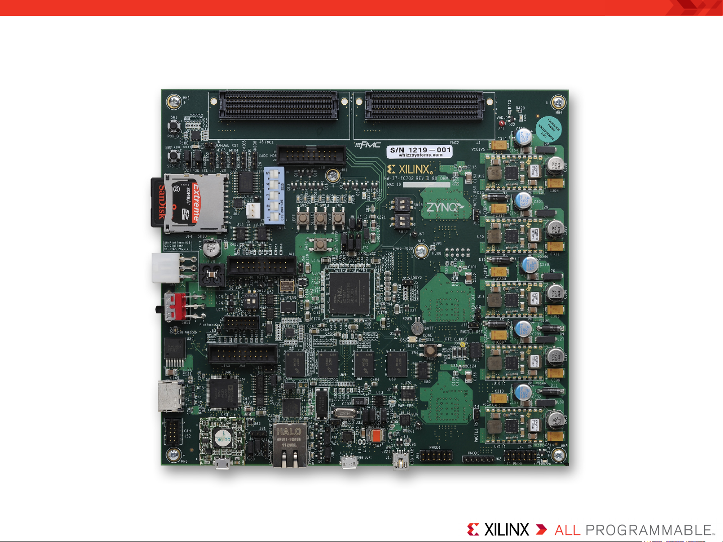
Xilinx ZC702 Board
Page 6
Vivado Software Requirements
Xilinx Vivado Design Suite 2014.4, Design Edition + SDK
– Combined installer
Note: Presentation applies to the ZC702
Page 7
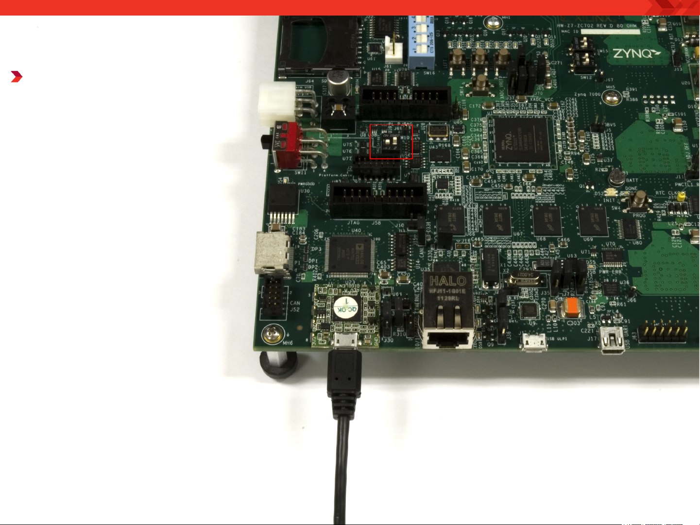
ZC702 Setup
Connect a USB TypeA to Micro-B cable to
the USB JTAG
(Digilent) connector
on the ZC702 board
– Connect this cable to
your PC
– Set the JTAG Select
Switch, SW10, to 01
– If using a Platform
Cable USB (II) JTAG
Cable, set SW10 to 10
Note: Presentation applies to the ZC702
Page 8
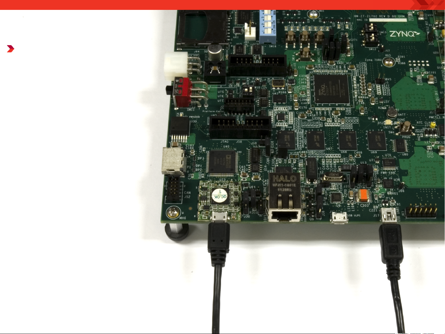
ZC702 Setup
Connect a USB TypeA to Mini-B cable to
the USB UART
connector on the
ZC702 board
– Connect this cable to
your PC
– Power on the ZC702
board for UART Drivers
Installation
Note: Presentation applies to the ZC702
Page 9
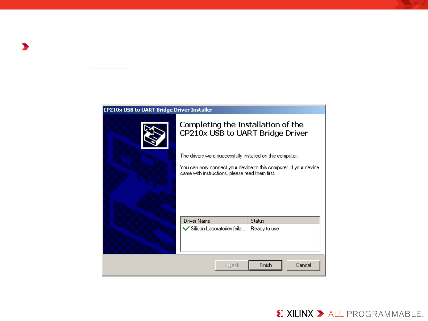
ZC702 Setup
Install USB UART Drivers
– Refer to UG1033 for details on installing the USB to UART Drivers
Note: Presentation applies to the ZC702
Page 10
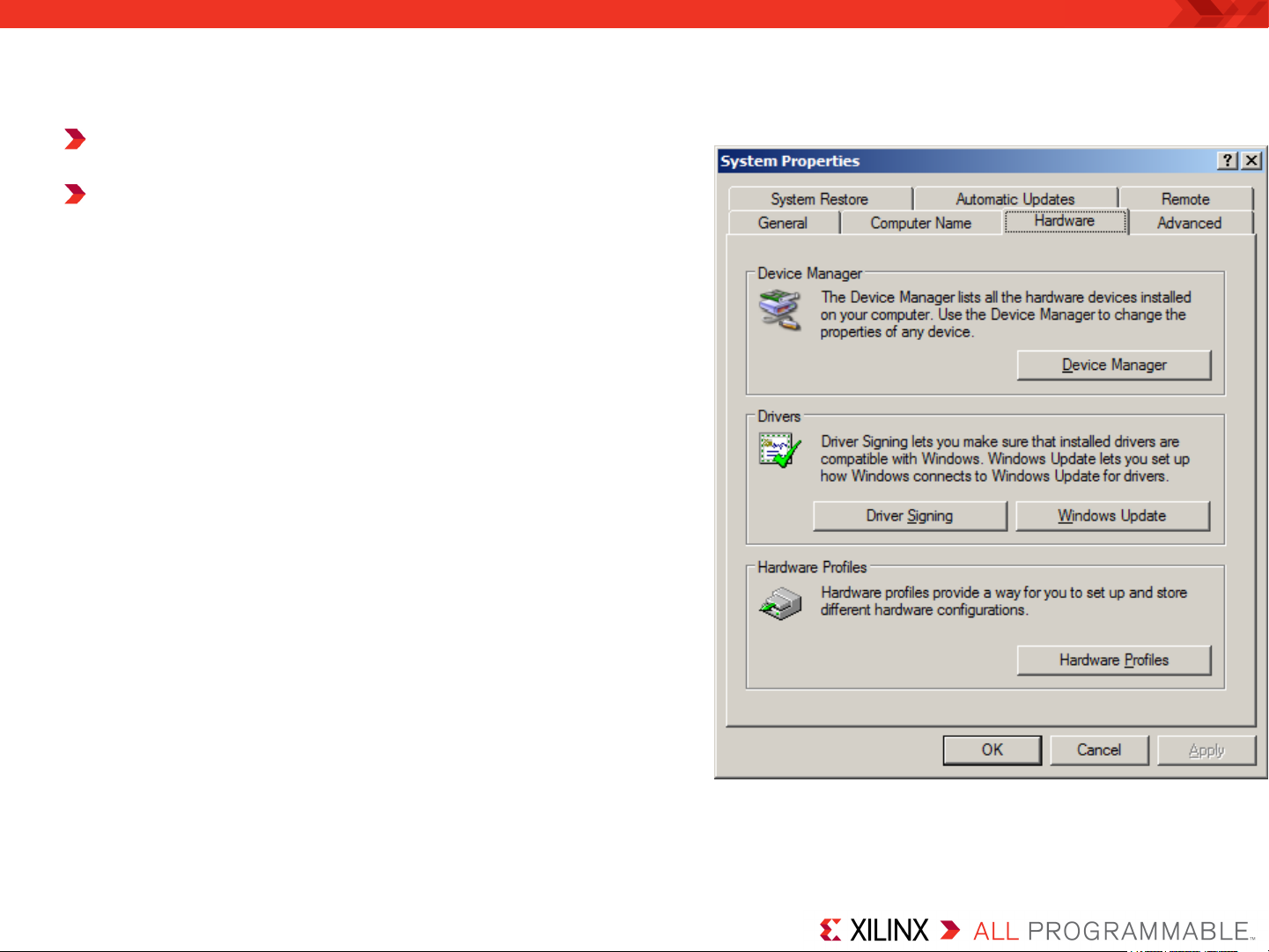
ZC702 Setup
Reboot your PC if necessary
Right-click on My Computer
and select Properties
– Select the Hardware tab
– Click on Device Manager
Note: Presentation applies to the ZC702
Page 11
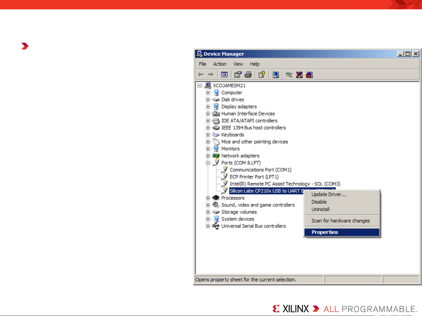
ZC702 Setup
Expand the Ports
Hardware
– Right-click on Silicon Labs
CP210x USB to UART
Bridge and select Properties
Note: Presentation applies to the ZC702
Page 12
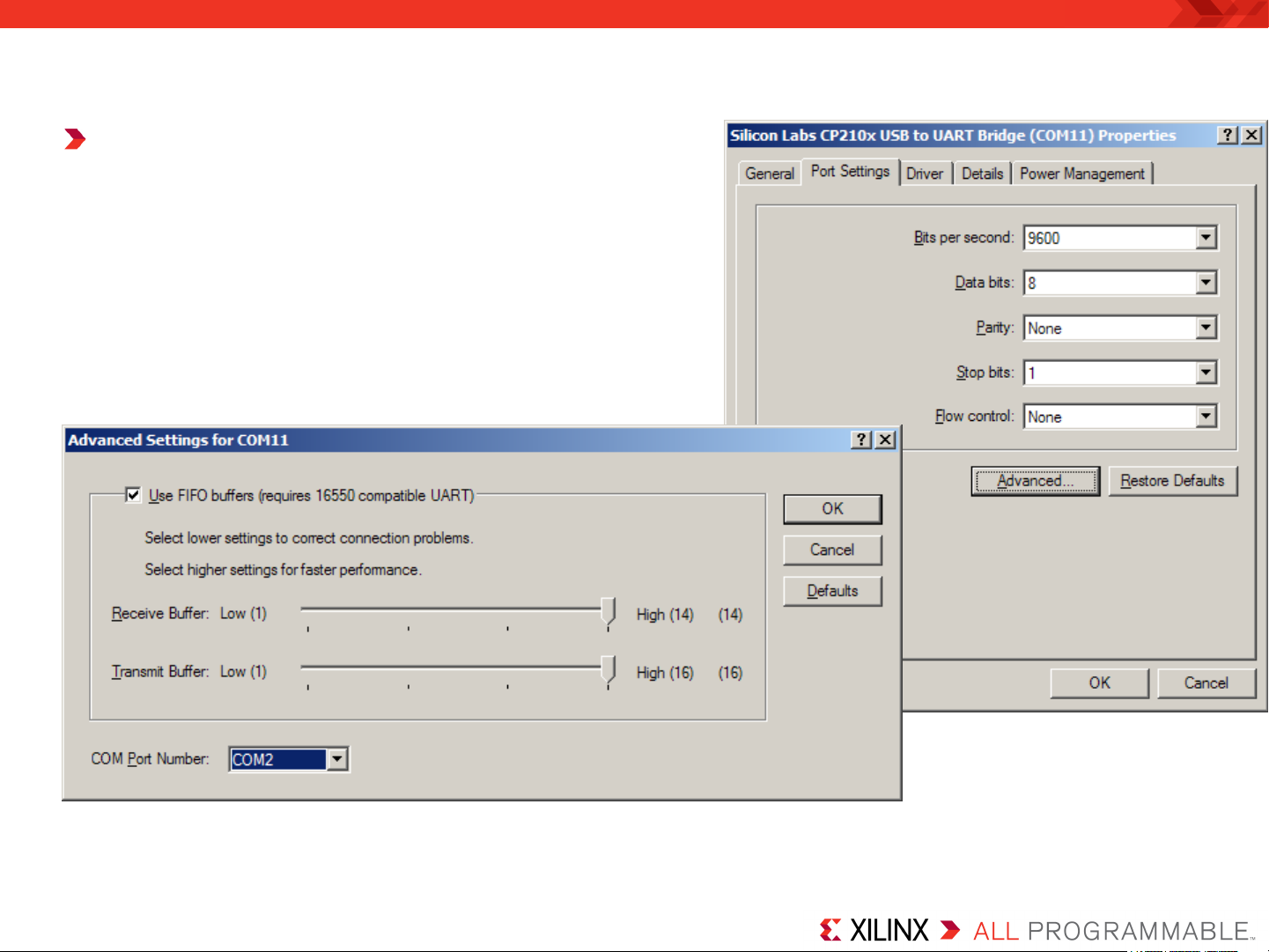
ZC702 Setup
Under Port Settings tab
– Click Advanced
– Set the COM Port to an open Com Port
setting from COM1 to COM4
Note: Presentation applies to the ZC702
Page 13

ZC702 Setup
Refer to UG1036 regarding Tera Term installation
Board Power must be on before starting Tera Term
Start the Terminal Program
– Select your USB Com Port
– Set the baud to 115200
Note: Presentation applies to the ZC702
Page 14

Si Labs Programmable Oscillator Calculator
Download and install ProgOscillatorSwInstall.zip
Note: Presentation applies to the ZC702
Page 15

Setup for ZC702 Si570 Programming
Unzip the ZC702 Si570 Programming Design Files (2014.4 C) ZIP file
– Available through http://www.xilinx.com/zc702
– It is recommended to unzip these design files to C:\ for SDK compatibility
Note: Presentation applies to the ZC702
Page 16

ZC702 Si570 Programming
Download the Si570 bitstream and ELF files
In a Windows CMD prompt type:
cd C:\zc702_si570_programming\ready_for_download
zc702_si570.bat
Note: AR47530 has been applied to the download script
Page 17

ZC702 Si570 Programming
Connect a scope to J63 (PMOD1), pins 4 and 6 to measure the
frequency
Si570 Power on frequency is 156.25 MHz
Frequency is divided by 10 in the Zynq PL
Measured frequency on these two pins will be ~15.625 MHz
Note: Presentation applies to the ZC702
Page 18

ZC702 Si570 Programming
For this example, Si570_0 will be reprogrammed from 156.25 to 200
MHz
– This requires use of the SiLabs Programmable Oscillator Calculator
To use the SiLabs calculator, the correct fXTAL value for each Si570
must be determined, using this equation:
For this equation,
– Fout = 156.25, the preprogrammed frequency of the Si570s on the ZC702
We need to determine:
– RFREQ
– HSDIV
– N1
These can be found by reading back the registers on the Si570
Note: Presentation applies to the ZC702
Page 19

ZC702 Si570 Programming
The terminal window shows the current register settings for the
Si570
– The power-on values will appear in the terminal window
– Note the value of 0x01C2BBFFFBA4
Note: The values reported by your
Si570 may differ from those shown
Page 20

ZC702 Si570 Programming
The value, 0x01C2BBFFFBA4, corresponds to the contents of the
Si570’s registers, 7 to 12:
Note: Presentation applies to the ZC702
Page 21

ZC702 Si570 Programming
Extract the HS_DIV and N1 values from 0x01C2BBFFFBA4 :
HS_DIV = 0b000 which corresponds to “4”
N1 = 0b0000111 which corresponds to “8”
Note: Presentation applies to the ZC702
Page 22

ZC702 Si570 Programming
Extract the RFREQ value from 0x01C2BBFFFBA4 :
– 02BBFFFBA4
Note: Presentation applies to the ZC702
Page 23

ZC702 Si570 Programming
Open the Window Calculator
Set to Scientific and Hex mode:
Note: Presentation applies to the ZC702
Page 24

ZC702 Si570 Programming
Enter or paste the RFREQ value, 02BBFEA811:
Convert it to Decimal
Note: Presentation applies to the ZC702
Page 25

ZC702 Si570 Programming
Divide by 2^28
This is the value for RFREQ:
Note: Presentation applies to the ZC702
Page 26

ZC702 Si570 Programming
For this equation,
– Fout = 156.25
– RFREQ = 43.74999584257602691650390625
– HSDIV = 4
– N1 = 8
– Fout x HSDIV x N1 = 5000
– fXTAL = 5000 / RFREQ
Note: Presentation applies to the ZC702
Page 27

ZC702 Si570 Programming
For this equation,
– Divide 43.74999584257602691650390625 by 5000
– Take the reciprocal
– fXTAL = 114.28572514592488006627271464555
– Ctrl-C to copy this value
Note: Presentation applies to the ZC702
Page 28

ZC702 Si570 Programming
Open the SiLabs Programmable Oscillator Calculator
– Select the Si570 and click OK
Note: Presentation applies to the ZC702
Page 29

ZC702 Si570 Programming
Select Options -> Advanced…
Page 30

ZC702 Si570 Programming
Paste in the value of fXTAL
– The calculator will round the number appropriately
– This allows us to calibrate the Si570 to a new frequency
– Click OK
Note: Presentation applies to the ZC702
Page 31

ZC702 Si570 Programming
Enter 156.25 under Definition and click the Apply Definition button
Page 32

ZC702 Si570 Programming
Set the new frequency to 200 MHz and click the Create Example
button
Page 33

ZC702 Si570 Programming
Under the summary tab,
the new register
configurations are shown
The startup register
configurations will vary
slightly from the actual
device power-on
programming
Note: Presentation applies to the ZC702
Page 34

ZC702 Si570 Programming
Press a key to begin entering the newly calculated values
When done, press “w”
Note: Presentation applies to the ZC702
Page 35

ZC702 Si570 Programming
Si570 has been successfully updated
Note: Presentation applies to the ZC702
Page 36

ZC702 Si570 Programming
Measured frequency will be ~20.00 MHz
Note: Presentation applies to the ZC702
Page 37

References
Page 38

References
Silicon Labs
– Si570 Data Sheet
• http://www.silabs.com/Support%20Documents/TechnicalDocs/si570.pdf
Page 39

Documentation
Page 40

Documentation
Zynq-7000
– Zynq-7000 All Programmable SoC
• http://www.xilinx.com/products/silicon-devices/soc/zynq-7000/index.htm
ZC702 Documentation
– Xilinx Zynq-7000 SoC ZC702 Evaluation Kit
• http://www.xilinx.com/products/boards-and-kits/EK-Z7-ZC702-G.htm
– ZC702 Hardware User Guide – UG850
• http://www.xilinx.com/support/documentation/boards_and_kits/
zc702_zvic/ug850-zc702-eval-bd.pdf
– ZC702 Getting Started Guide – UG926
• http://www.xilinx.com/support/documentation/boards_and_kits/
zynq-7000/zc702_gsg/v3_0/UG926_Z7_ZC702_Eval_Kit.pdf
 Loading...