

XILINX XC2C64-7VQ44I, XC2C64-7VQ44C, XC2C64-7VQ100I, XC2C64-7VQ100C, XC2C64-7PC44I Datasheet
...
DS092 (v1.0) January 3, 2002 www.xilinx.com 1
Advance Product Specification 1-800-255-7778
© 2002 Xilinx, Inc. All rights reserved. All Xilinx trademarks, registered trademarks, patents, and disclaimers are as listed at http://www.xilinx.com/legal.htm.
All other trademarks and registered trademarks are the property of their respective owners. All specifications are subject to change without notice.
Features
• Optimized for 1.8V systems
- Industry’s fastest low power CPLD
- Static Icc of less than 100 microamps at all times
- Densities from 32 to 512 macrocells
• Industry’s best 0.18 micron CMOS CPLD
- Optimized architecture for effective logic synthesis
- Multi-voltage I/O operation — 1.5V to 3.3V
• Available in multiple package options
- 44-pin PLCC with 33 user I/O
- 44-pin VQFP with 33 user I/O
- 56-ball CP (0.05mm) BGA with 45 user I/O
- 100-pin VQFP with 64 user I/O
• Advanced syste m features
- Fastest in system programming
· 1.8V ISP using IEEE 1532 (JTAG) interface
- IEEE1149.1 JTA G Boundary Scan Test
- Optional Schmitt trigger input (per pin)
- Unsurpassed low power management
- FZP 100% CMOS product ter m gene ration
- Flexible clocking modes
· Optional DualEDGE triggered registers
- Global signal options with macrocell control
· Multiple global clocks with phase selection per
macrocell
· Multiple global output enables
· Global set/reset
- Abundant product term clocks, output enables and
set/resets
- Efficient control term clocks, output enables and
set/resets for each macrocell and shared across
function blocks
- Advanced design security
- Open-drain output option for Wired-OR and LED
drive
- Optional bus-hold or weak pullup on selected I/O
pins
- Optional configurable grounds on unused I/Os
- Mixed I/O voltages compatible with 1.5V, 1.8V,
2.5V, and 3.3V logic levels on all parts
- PLA architecture
· Superior pinout retention
· 100% product term routability across function
block
- Hot pluggable
- Design entry /verification using Xilinx and industry
standard CAE tools
- Free software support for all densities using Xilinx
WebPACK™ or WebFITTER™ tools
- Industr y leading nonvolatile 0.18 micron CMOS
process
- Guaranteed 1,000 program /era se cycl e s
- Guaranteed 20 year data retention
Refer to the CoolRunner™-II family data sheet for architec-
ture description.
Description
The CoolRunner-II 64-macrocell device is designed for both
high performance and low po wer applications. This lends
power savings to high-end communication equipment and
high speed to battery operated devices. Due to the low
power stand-by and dynamic operation, overall system reliability is improved
This device consists of four Function Blocks inter-connected by a low power Advanced Interconnect Matrix (AIM).
The AIM feeds 40 true and complement inputs to each
Function Block. The Function Blocks consist of a 40 by 56
P-term PLA and 16 macrocells which contain numerous
configuration bits that allow for combina tional or registered
modes of operation.
Additionally, these registers can be globally reset or preset
and configured as a D or T flip-flop or as a D latch. T here
are also multiple clock signals, both global and local product
term types, configured on a per macrocell basis. Output
control signals include slew rate control, bus hold and open
drain. A Schmitt trigger input is available on a per input pin
basis. In addition to com binatorial and registered outputs,
the registers may be configured as fast inputs.
Clocking is available on a global or Function Block basis.
Three global clocks are available for all Fun ction Blocks as
a synchronous clock source. These clocks are additionally
used to set or preset individual macrocell registers on
power up. Local clocks are generated i n specific Function
Blocks and only available to macrocell registers in that
Function Block.
A DualEDGE flip-flop feature is also available on a per macrocell basis. This feature allows performance where it is
needed without raisin g the total power consum ption of the
entire device.
The CoolRunner-II 64-macrocell CPLD is I/O compatible
with standard LVTTL33 and LVCMOS18, 25, and 33 volts
(see Table 1). This device is also 1.5 volt I/O compatible
with the use of Schmitt inputs.
0
XC2C64 CoolRunner-II CPLD
DS092 (v1.0) January 3, 2002
00
Advance Product Specification
R
XC2C64 CoolRunner-II CPLD
2 www.xilinx.com DS092 (v1.0) Janu ary 3, 2002
1-800-255-7778 Advance Product Specification
R
Fast Zero Power Design Technology
Xilinx CoolRunner-II CPLDs are fabricated on a 0.18 micron
process technology which is derived from leading edge
FPGA product development. Cool Runner-II CPLDs em ploy
Fast Zer o Power™ (FZP), a design tec hnique that makes
use of CMOS technology in both the fabrication and design
methodology. FZP design technology employs a cascade of
CMOS gates to implement sum of products instead of traditional sense amplifier m ethodolog y. Due to this technology,
Xilinx CoolRunner-II CPLDs achieve both high performance
and low power operation.
Support ed I/O S tandards
The CoolRunner-II 64 macrocell features both LVCMOS
and LVTTL I/O implementations. See Table 1 for I/ O stan-
dard voltages. The LVTTL I/O standard is a general purpose
EIA/JESDSA standard for 3.3V applications that use an
LVTTL input buffer and Push-Pull output buffer. The LVCMOS standard is used in 3.3V, 2.5V, 1.8V applications.
CoolRunner-II CPLDs are also 1.5V I/O compatible with the
use of Schmitt inputs.
Table 1: I/O Standards for XC2 C64
I/O
Standard
Output
V
CCIO
Input
V
CCIO
Input
V
REF
Board
Termination
Voltage V
T
LVTTL 3.3V 3.3V N/A N/A
LVCMOS33 3.3 3.3 N/A N/A
LVCMOS25 2.5 2.5 N/A N/A
LVCMOS18 1.8 1.8 N/A N/A
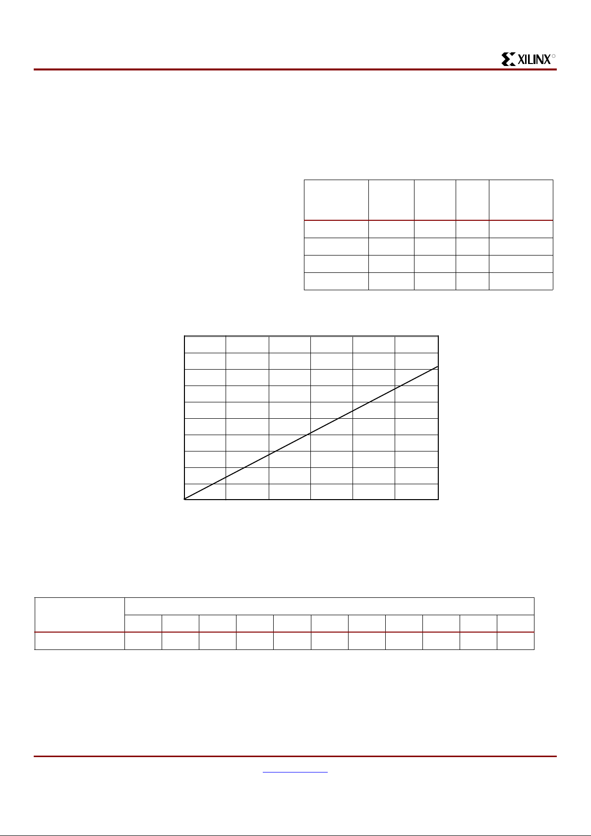
Figure 1: ICC vs Frequency
Table 2: I
CC
vs Frequency (LVCMOS 1.8V TA = 25°C)
(1)
Frequency (MHz)
50 75 100 125 150 175 200 225 250 275 300
Typical I
CC
(mA) 3.6 5.5 7.3 9.1 10.8 12.5 14.2 15.9 17.5 19.2 20.8
Notes:
1. 16-bit up/do wn, r esettable binary counter (one counter per funct ion block).
Frequency (MHz)
DS092_07_121501
I
CC
(mA)
0
0
5
10
15
20
25
30025020015010050
XC2C64 CoolRunner-II CPLD
DS092 (v1.0) January 3, 2002 www.xilinx.com 3
Advance Product Specification 1-800-255-7778
R
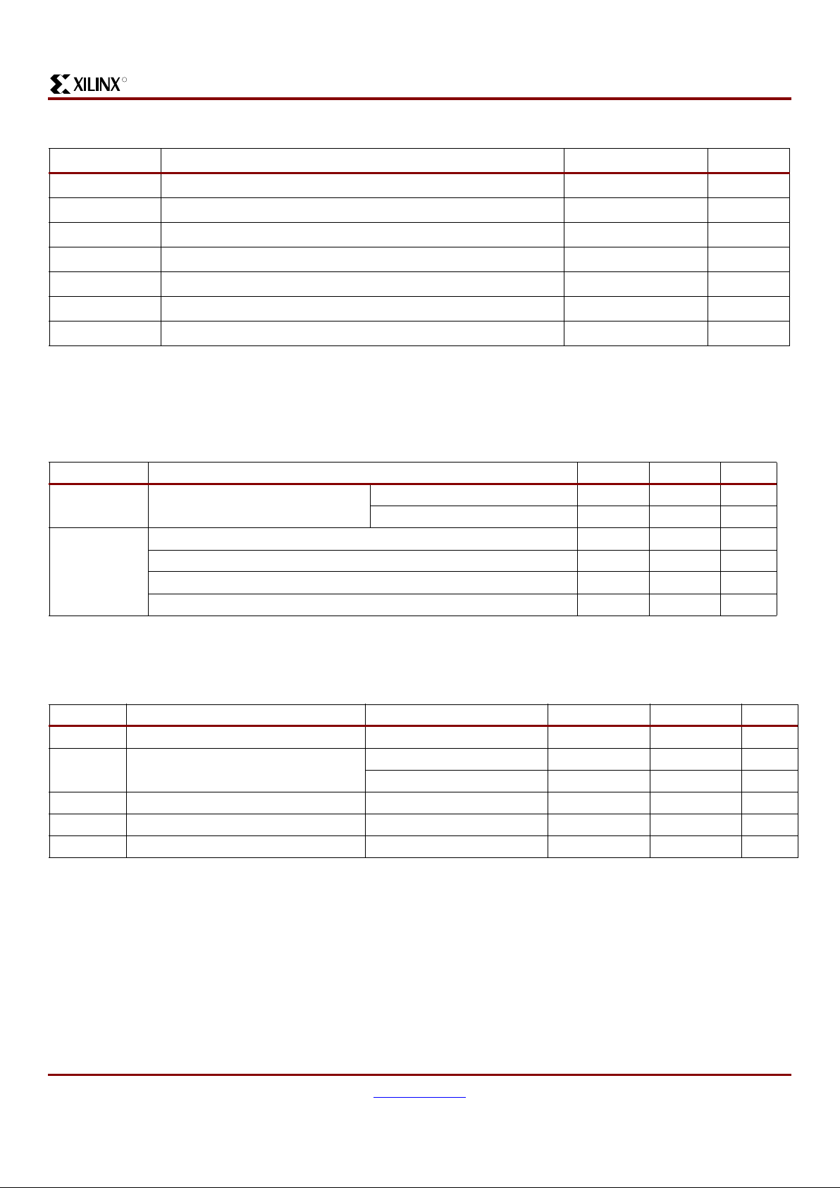
Recommended Operating Conditi ons
DC Electrical Characteristics (Over Recommended Operating Conditions)
Absolute Maximum Ratings
Symbol Description Value Units
V
CC
Supply voltage relative to ground –0.5 to 2.0 V
V
CCIO
Supply voltage for output drivers –0.5 to 4.0 V
V
IN
Input voltage relative to ground
(1)
–0.5 to 4.0 V
V
TS
Voltage applied to 3-state output
(1)
–0.5 to 4.0 V
V
STG
Storage Temperature (ambient) –65 to +150 °C
T
SOL
Maximum Soldering temperature (10s @ 1/16in. = 1.5mm) + 60 °C
T
J
Junction Temperature + 50 °C
Notes:
1. Maximum DC undershoot below GND must be limited to either 0.5V or 10 mA, whichever is easiest to achieve. During tran sitions,
the device pins may under shoot to –2.0v or overshoot to +4.5V, provided this over or undershoot l asts less than 10 ns and with the
forcing current being limited to 200 mA.
Symbol Parameter Min Max Units
V
CC
Supply voltage for internal logic
and input buffers
Commercial TA = 0°C to +70°C1.7 1.9 V
Industrial T
A
= –40°C to +85°C1.7 1.9 V
V
CCIO
Supply voltage for output drivers @ 3.3V operation 3.0 3.6 V
Supply voltage for output drivers @ 2.5V operation 2.3 2.7 V
Supply voltage for output drivers @ 1.8V operation 1.7 1.9 V
Supply voltage for output drivers @ 1.5V operation
(1)
1.4 1.6 V
Notes:
1. Use input hysteresis for 1.5V LVCMOS.
Symbol Parameter Test Conditions Min. Max. Units
I
CCSB
Standby current V
CC
= 1.9V, V
CCIO
= 3.6V 100 µA
I
CC
Dynamic current f = 1 MHz mA
f = 50 MHz mA
C
JTA G
JTAG input capacitance f = 1 MHz pF
C
CLK
Global clock input capacitance f = 1 MHz pF
C
IO
I/O capacitance f = 1 MHz pF
XC2C64 CoolRunner-II CPLD
4 www.xilinx.com DS092 (v1.0) Janu ary 3, 2002
1-800-255-7778 Advance Product Specification
R
LVCMOS 3.3V DC Voltage Specifications
LVCMOS 2.5V DC Voltage Specifications
Symbol Parameter Test Conditions Min. Max. Units
V
CCIO
Input source voltage 3.0 3.6 V
V
IH
High level input voltage 2 V
CCIO
+ 0.3V V
V
IL
Low level input voltage –0.3 0.8 V
V
OH
High l evel output voltag e IOH = –8 mA, V
CCIO
= 3V V
CCIO
– 0.4V - V
I
OH
= –0.1 mA, V
CCIO
= 3V V
CCIO
– 0.2V - V
V
OL
Low level output voltage IOL = 8 mA, V
CCIO
= 3V - 0.4 V
I
OL
= 0.1 mA, V
CCIO
= 3V - 0.2 V
I
IL
Input leakage current VIN = 0V or V
CCIO
to 3.9V –10 10 µA
I
IH
I/O High-Z leakage VIN = 0V or V
CCIO
to 3.9V –10 10 µA
C
JTA G
JTAG input capacitance f = 1 MHz pF
C
CLK
Global clock input capacitance f = 1 MHz pF
C
IO
I/O capacita nce f = 1 MHz pF
Symbol Parameter Test Conditions Min. M ax. Units
V
CCIO
Input source voltage 2.3 2.7 V
V
IH
High level input voltage 1.7 3.9 V
V
IL
Low level input voltage –0.3 0.7 V
V
OH
High l evel output voltag e IOH = –8 mA, V
CCIO
= 3V V
CCIO
– 0.4V - V
I
OH
= –0.1 mA, V
CCIO
= 3V V
CCIO
– 0.2V - V
V
OL
Low level output voltage IOL = 8 mA, V
CCIO
= 3V - 0.4 V
I
OL
= 0.1mA, V
CCIO
= 3V - 0.2 V
I
IL
Input leakage current VIN = 0V or V
CCIO
to 3.9V –10 10 µA
I
IH
I/O High-Z leakage VIN = 0V or V
CCIO
to 3.9V –10 10 µA
C
JTA G
JTAG input capacitance f = 1 MHz pF
C
CLK
Global clock input capacitance f = 1 MHz pF
C
IO
I/O capacitance f = 1 MHz pF

XC2C64 CoolRunner-II CPLD
DS092 (v1.0) January 3, 2002 www.xilinx.com 5
Advance Product Specification 1-800-255-7778
R
LVCMOS 1.8V DC Voltage Specifications
1.5V DC Voltage Specifications
Symbol Parameter Test Conditions Min. Max. Units
V
CCIO
Input source voltage 1.7 1.9 V
V
IH
High level input voltage 0.7 x V
CCIO
3.9 V
V
IL
Low level input voltage –0.3 0.2 x V
CCIO
V
V
OH
High l evel output voltag e IOH = –8 mA, V
CCIO
= 3V V
CCIO
-0.45 - V
I
OH
= –0.1 mA, V
CCIO
= 3V V
CCIO
-0.2 - V
V
OL
Low level output voltage IOL = 8 mA, V
CCIO
= 3V - 0.45 V
I
OL
= 0.1 mA, V
CCIO
= 3V - 0.2 V
I
IL
Input leakage current VIN = 0 or V
CCIO
to 3.9V –10 10 µA
I
IH
I/O High-Z leakage VIN = 0 or V
CCIO
to 3.9V –10 10 µA
C
JTAG
JTAG input capacitance f = 1 MHz pF
C
CLK
Global clock input capacitance f = 1 MHz pF
C
IO
I/O capacitance f = 1 MHz pF
Symbol Parameter Te s t Con ditions Min. Max. Units
V
CCIO
Input source voltage 1.4 1.6 V
V
IH
High level input voltage 0.7 x V
CCIO
3.9 V
V
IL
Low level input voltage –0.3 0.3 V
V
OH
High l evel output voltag e IOH = –8 mA, V
CCIO
= 3V V
CCIO
– 0.45 V
I
OH
= –0.1 mA, V
CCIO
= 3V V
CCIO
– 0.2 V
V
OL
Low level output voltage IOL = 8 mA, V
CCIO
= 3V 0.4 V
I
OL
= 0.1 mA, V
CCIO
= 3V 0.2 V
I
IL
Input leakage current VIN = 0 or V
CCIO
to 3.9V –10 10 µA
I
IH
I/O High-Z leakage VIN = 0 or V
CCIO
to 3.9V –10 10 µA
C
JTA G
JTAG input capacitance f = 1 MHz pF
C
CLK
Global clock input capacitance f = 1 MHz pF
C
IO
I/O capacitance f = 1 MHz pF

XC2C64 CoolRunner-II CPLD
6 www.xilinx.com DS092 (v1.0) Janu ary 3, 2002
1-800-255-7778 Advance Product Specification
R
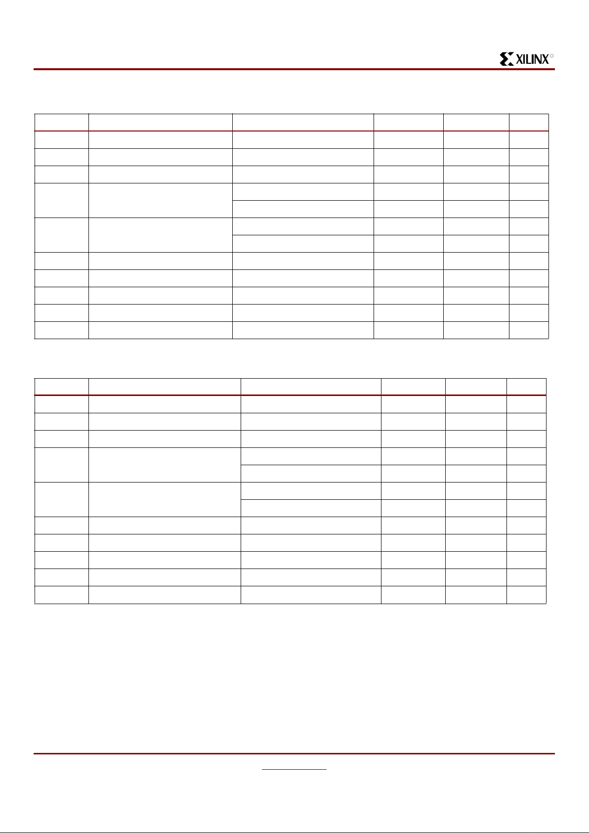
AC Electrical Characteristics Over Recommended Operating Conditions
Symbol Parameter
-4 -5 -7
UnitsMin. Max. Min. Max. Min. Max.
T
PD1
Propagation delay single p-term - 3.7 - 4.6 - 6.7 ns
T
PD2
Propagation delay OR array - 4.0 - 5.0 - 7.5 ns
T
SU1
Setup time fast 1.6 - 1.9 - 2.3 - ns
T
SU2
Setup time 2.0 - 2.4 - 3.3 - ns
T
H1
Fast input register hold time 0 - 0 - 0 - ns
T
H2
P-term hold time 0 - 0 - 0 - ns
T
CO
Clock to output - 3.0 - 3.9 - 6.0 ns
T
TOGGLE
Internal toggle rate - 416 - 2 50 - 168 MHz
F
SYSTEM
Maximum system frequency - 2 70 - 213 - 141 MHz
F
EXT
Maximum external frequency - 200 - 159 - 108 MHz
T
PSU1
Fast input register p-term clock setup time 1.0 - 1.2 - 1.5 - ns
T
PSU2
P-term clock setup time 1.4 - 1.7 - 2.5 - ns
T
PH1
Fast input register p-term clock hold time 0.4 - 0.6 - 0.7 - ns
T
PH2
P-term clock hold 0.3 - 0.5 - 0.5 - ns
T
PCO
P-term clock to output - 3.6 - 4.6 - 6.8 ns
T
OE/TOD
Global OE to output enable/disable - 3.9 - 4.9 - 7.0 ns
T
POE/TPOD
P-term OE to output enable/disable - 4. 3 - 5.3 - 7.3 ns
T
MOE/TMOD
Macrocell driven OE to output enable/disable - 4.9 - 6.3 - 9.2 ns
T
PAO
P-term set/reset to output valid - 5.4 - 6.4 - 9.1 ns
T
AO
Global set/reset to output valid - 5.5 - 6.5 - 9.3 ns
T
SUEC1
Fast input register clock enable setup time 1.6 - 1.9 - 2.3 - ns
T
SUEC2
Register clock enable setup time 2.0 - 2.4 - 3.3 - ns
T
HEC1
Fast input register clock enable hold time 0 - 0 - 0 - ns
T
HEC2
Register clock enable hold time 0 - 0 - 0 - ns
T
CW
Global clock pulse width High or Low 1.2 - 2.0 - 3.0 - ns
T
PCW
P-term pulse width High or Low 4.0 - 5.0 - 7.5 - ns
T
CONFIG
Configuration time us

XC2C64 CoolRunner-II CPLD
DS092 (v1.0) January 3, 2002 www.xilinx.com 7
Advance Product Specification 1-800-255-7778
R
Internal Timing Parameters
Symbol Parameter
(1)
-4 -5 -7
UnitsMin. Max. Min. Max. Min. Max.
Buffer Delays
T
IN
Input buffer delay - 1.3 - 1.7 - 2.4 ns
T
FIN
Fast data register input delay - 1.6 - 2.1 - 3.0 ns
T
GCK
Global Clock buffer delay - 1.2 - 1.6 - 2.5 ns
T
GSR
Global set/reset buffer delay - 1.9 - 2.4 - 3.5 ns
T
GTS
Global 3-state buffer delay - 1.4 - 1.9 - 3.0 ns
T
OUT
Output buffer delay - 1.6 - 1.9 - 2.8 ns
T
EN
Output buffer enable/disable delay - 2.5 - 3.0 - 4.0 ns
P-term Delays
T
CT
Control term delay - 0.5 - 0.6 - 0.9 ns
T
LOGI1
Single P-term delay adder - 0.4 - 0.5 - 0.8 ns
T
LOGI2
Multiple P-term delay adder - 0.3 - 0.4 - 0.8 ns
Macrocell Delay
T
PDI
Input to output valid - 0.4 - 0.5 - 0.7 ns
T
SUI
Setup before clock 1.2 - 1.4 - 1.8 - ns
T
HI
Hold after clock 0 - 0 - 0 - ns
T
ECSU
Enable clock setup time 1.2 - 1.4 - 1.8 - ns
T
ECHO
Enable clock hold time 0 - 0 - 0 - ns
T
COI
Clock to output valid - 0.2 - 0.4 - 0.7 ns
T
AOI
Set/reset to output valid - 2.0 - 2.2 - 3.0 ns
T
CDBL
Clock doubler delay - 0 - 0 - 0 ns
Feedback Delays
T
F
Feedback delay - 1.6 - 2.0 - 3.0 ns
T
OEM
Macrocell to global OE delay - 1.0 - 1.3 - 2.0 ns
I/O Standard Time Adder Delays 1.5V CMOS
T
IN15
Standard input adder ns
T
HYS15
Hysteresis input adder ns
T
OUT15
Output adder ns
T
SLEW15
Output slew rate adder ns
I/O Standard Time Adder Delays 1.8V CMOS
T
IN18
Standard input adder - 0 - 0 - 0 ns
T
HYS18
Hysteresis input adder - 2.0 - 3.0 - 4.0 ns
T
OUT18
Output adder - 0 - 0 - 0 ns
T
SLEW
Output slew rate adder - 2.0 - 3.0 - 4.0 ns

XC2C64 CoolRunner-II CPLD
8 www.xilinx.com DS092 (v1.0) Janu ary 3, 2002
1-800-255-7778 Advance Product Specification
R
Switching Characteristics
I/O Standard Time Adder Delays 2.5V CMOS
T
IN25
Standard input adder - 0.5 - 0.8 - 1.0 ns
T
HYS25
Hysteresis input adder - 1.5 - 2.5 - 3.0 ns
T
OUT25
Output adder - 1.5 - 2.5 - 3.0 ns
T
SLEW25
Output slew rate adder - 2.0 - 3.0 - 4.0 ns
I/O Standard Time Adder Delays 3.3V CMOS/TTL
T
IN33
Standard input adder - 0.7 - 1.0 - 2.0 ns
T
HYS33
Hysteresis input adder - 1.0 - 2.0 - 3.0 ns
T
OUT33
Output adder - 1.0 - 2.0 - 3.0 ns
T
SLEW33
Output slew rate adder - 2.0 - 3.0 - 4.0 ns
Notes:
1. 1.5 ns input pin signal rise/fall.
Internal Timing Parameters (Continued)
Symbol Parameter
(1)
-4 -5 -7
UnitsMin. Max. Min. Max. Min. Max.
Number of Outputs Switching
1 2 4 8 12 16
4.0
4.4
5.8
VCC = 1.8V, 25oC
T
PD_PAL
(ns)
6.0
5.6
4.2
DS092_09_121501

XC2C64 CoolRunner-II CPLD
DS092 (v1.0) January 3, 2002 www.xilinx.com 9
Advance Product Specification 1-800-255-7778
R
Note: GTS = global output ena ble, GRS = global reset /set,
GCK = global clock x
Pin Des cr ip t io ns
Function
Block
Macro-
cell PC44 VQ44 CP56 VQ100
1 1 44 38 F1 13
1 2 43 37 E3 12
134236E111
14---10
15---9
16---8
17--D37
18---6
1(GTS1) 9 40 34 D1 4
1(GTS0)103933C13
1(GTS3) 11 38 32 A3 2
1(GTS2) 12 37 31 A2 1
1(GRS) 13 36 30 B1 99
114--A197
115--C394
116--A492
21139G114
22240F315
23---16
24---17
25341H118
26442G319
2(GCK0) 7 5 43 J1 22
2(GCK1) 8 6 44 K1 23
29--K424
2(GCK2) 10 7 1 K2 27
211---28
21282K329
21393H330
214--K532
215---33
216---34
3 1 35 29 C4 91
3 2 34 28 A4 90
3 3 33 27 C5 89
34--A781
35--C879
3 6 29 23 A8 78
37--A977
38---76
39--A574
3 10 28 22 A10 72
3 11 27 21 B10 71
3 12 26 20 C10 70
313--D868
3142519E867
3 15 24 18 D10 64
316---61
41115K635
42126H536
43---37
44---39
45--H740
46---41
47148H842
48---43
49---49
410--K850
4 11 18 12 H10 52
412---53
4 13 19 13 G10 55
4142014-56
4 15 22 16 F10 58
4 16 - - E10 60
Pin Descriptions (Continued)
Function
Block
Macro-
cell PC44 VQ44 CP56 VQ100

XC2C64 CoolRunner-II CPLD
10 www.xilinx.com DS092 (v1.0) Janu ary 3, 2002
1-800-255-7778 Advance Product Specification
R
XC2C64 Global, JTAG, Power/Ground and No Connect Pins
Ordering Information
Pin Type PC 44 VQ44 CP56 VQ1 00
TCK 17 11 K10 48
TDI 15 9 J10 45
TDO 30 24 A6 83
TMS 16 10 K9 47
V
AUX
(JTAG supply voltage) 41 35 D3 5
Power internal (V
CC
)
Power exter nal I/O (V
CCIO
)
21 15 G8 26,57
13, 32 7,26 H6, C6 38, 51,88, 98
Ground 10,23,31 4,17,25 H4, F8, C7 21,31,62,69,84,100
No connects 20,25,44,46,54,59,63,65,66,73, 75,
80,82,85,86,87,93,95,96
Total user I/O 33 33 45 64
Part Number
Pin/Ball
Spacing
θ
JA
(C/Watt)
θJC
(C/Watt) Package Type I/O
Commercial (C)
Industrial (I)
XC2C64-4PC44C 1.27mm 53.1 28.7 Plastic Leaded Chip Carrier 33 C
XC2C64-5PC44C 1.27mm 53.1 28.7 Plastic Leaded Chip Carrier 33 C
XC2C64-7PC44C 1.27mm 53.1 28.7 Plastic Leaded Chip Carrier 33 C
XC2C64-4VQ44C 0.8mm 46.6 8.2 Very Thin Quad Flat Pack 33 C
XC2C64-5VQ44C 0.8mm 46.6 8.2 Very Thin Quad Flat Pack 33 C
XC2C64-7VQ44C 0.8mm 46.6 8.2 Very Thin Quad Flat Pack 33 C
XC2C64-4CP56C 0.5mm 65.0 15.0 Chip Scale Package 45 C
XC2C64-5CP56C 0.5mm 65.0 15.0 Chip Scale Package 45 C
XC2C64-7CP56C 0.5mm 65.0 15.0 Chip Scale Package 45 C
XC2C64-4VQ100C 0.5mm 53.2 14.6 Very Thin Quad Flat Pack 64 C
XC2C64-5VQ100C 0.5mm 53.2 14.6 Very Thin Quad Flat Pack 64 C
XC2C64-7VQ100C 0.8mm 53.2 14.6 Very Thin Quad Flat Pack 64 C
XC2C64-5PC44I 1.27mm 53.1 28.7 Plastic Leaded Chip Carrier 33 I
XC2C64-7PC44I 1.27mm 53.1 28.7 Plastic Leaded Chip Carrier 33 I
XC2C64-5VQ44I 0.8mm 46.6 8.2 Very Thin Quad Flat Pack 33 I
XC2C64-7VQ44I 0.8mm 46.6 8.2 Very Thin Quad Flat Pack 33 I
XC2C64-5CP56I 0.5mm 65.0 15.0 Chip Scale Package 45 I
XC2C64-7CP56I 0.5mm 65.0 15.0 Chip Scale Package 45 I
XC2C64-5VQ100I 0.5mm 53.2 14.6 Very Thin Quad Flat Pack 64 I
XC2C64-7VQ100I 0.5mm 53.2 14.6 Very Thin Quad Flat Pack 64 I

XC2C64 CoolRunner-II CPLD
DS092 (v1.0) January 3, 2002 www.xilinx.com 11
Advance Product Specification 1-800-255-7778
R
Figure 2: PQ44 Package
PQ44
Top View
I/O
V
CCIO
Gnd
TDO
I/O
I/O
I/O
I/O
I/O
I/O
GND
I/O
I/O
I/O
V
AUX
I/O
(1)
I/O
(1)
I/O
(1)
I/O
(1)
I/O
(3)
I/O
I/O
I/O
V
CCIO
I/O
TDI
TMS
TCK
I/O
I/O
I/O
V
CC
I/O
I/O
I/O
I/O
I/O
I/O
(2)
I/O
(2)
I/O
(2)
I/O
I/O
GND
I/O
1
2
3
4
5
6
7
8
9
10
11
1213141516171819202122
33
32
31
30
29
28
27
26
25
24
23
4443424140393837363534
(1) - Global Output Enable
(2) - Global Clock
(3) - Global Set/Reset
Figure 3: VQ44 Package
VQ44
Top View
I/O
(1)
I/O
(1)
I/O
(1)
I/O
(3)
I/O
I/O
I/O
V
CCIO
GND
TDO
I/O
I/O
(2)
I/O
(2)
I/O
I/O
I/O
I/O
I/O
I/O
I/O
V
AUX
I/O
(1)
I/O
I/O
I/O
V
CC
I/O
GND
I/O
I/O
I/O
I/O
I/O
I/O
(2)
I/O
I/O
GND
I/O
I/O
V
CCIO
I/O
TDI
TMS
TCK
1
2
3
4
5
6
7
8
9
10
11
1213141516171819202122
33
32
31
30
29
28
27
26
25
24
23
4443424140393837363534
(1) - Global Output Enable
(2) - Global Clock
(3) - Global Set/Reset
Figure 4: CP56 Package
CP56
Bottom View
I/O
(2)
I/O
(2)
I/O I/O I/O I/O I/O I/O TMS TCK
I/O
(2)
TDI
I/O I/O GND I/O
V
CCIO
I/O I/O I/O
I/O I/O V
CC
I/O
I/O I/O GND I/O
I/O I/O I/O I/O
I/O
(1)
V
AUX
I/O I/O
I/O
(1)
I/O I/O I/O
V
CCIO
GND I/O I/O
I/O
(3)
I/O
I/O I/O
(1)
I/O I/O I/O TDO I/O I/O I/O I/O
K
J
H
G
F
E
D
C
B
A
1
2
3
4
5
6
7
8
9
10
(1) - Global Output Enable
(2) - Global Clock
(3) - Global Set/Reset

XC2C64 CoolRunner-II CPLD
12 www.xilinx.com DS092 (v1.0) Janu ary 3, 2002
1-800-255-7778 Advance Product Specification
R
Revision History
The following table shows the revision history for this document.
Figure 5: V Q100 Package
Date Version Revision
01/03 /02 0 .1 Initia l X ilin x re lea s e.
VQ100
Top View
GND
I/O
(3)
V
CCIO
I/ONCNC
I/ONCI/O
I/O
I/O
I/O
V
CCIO
NCNCNC
GND
TDONCI/ONCI/O
I/O
I/O
I/O
V
CC
I/O
(2)
I/O
I/O
I/O
GND
I/O
I/O
I/O
I/O
I/O
I/O
V
CCIO
I/O
I/O
I/O
I/O
I/O
NC
TDI
NC
TMS
TCK
I/O
I/O
NC
I/O
NC
I/O
I/O
I/O
GND
I/O
I/O
NC
NC
I/O
NC
GND
I/O
I/O
NC
I/O
Vcc
I/O
I/O
NC
I/O
I/O
V
CCIO
I/O
(1)
I/O
(1)
I/O
(1)
I/O
(1)
V
AUX
I/O
I/O
I/O
I/O
I/O
I/O
I/O
I/O
I/O
I/O
I/O
I/O
I/O
I/O
NC
GND
I/O
(2)
I/O
(2)
I/O
NC
1
2
3
4
5
6
7
8
9
10
11
12
13
14
15
16
17
18
19
20
21
22
23
24
25
75
74
73
72
71
70
69
68
67
66
65
64
63
62
61
60
59
58
57
56
55
54
53
52
51
26272829303132333435363738394041424344454647484950
100
9998979695949392919089888786858483828180797877
76
(1) - Global Output Enable
(2) - Global Clock
(3) - Global Set/Reset
 Loading...