

XP SERIES
User Manual
1

Important Safety Information
1. READ THESE INSTRUCTIONS
All the safety and operating instructions should be read before the product is operated.
2. KEEP THESE INSTRUCTIONS
The safety and operating instructions should be retained for future reference.
3. HEED ALL WARNINGS
All warnings on the product and in the operating instructions should be adhered to.
4. FOLLOW ALL INSTRUCTIONS
All operating and use of instructions should be followed.
5. DO NOT USE THIS APPARATUS IN WATER.
Do not use the product near water. For example, near a bathtub, wash bowl, kitchen sink, or laundry tub, in a wet basement, or near a
swimming pool, and the like.
6. CLEAN ONLY WITH DRY CLOTH.
Unplug the unit from the wall outlet before cleaning.
7. DO NOT BLOCK ANY VENTILATION OPENINGS
Slots and openings in the cabinet back or bottom are provided for ventilation, to ensure reliable operation of the limit and to protect it from
overheating. These openings must not be blocked or covered. The openings should never be blocked by placing the product on a bed, sofa,
rug, or similar surface. This product should never be placed near or over a radiator or heat source. This product should not be placed in a
built-in installation such as a bookcase or rack unless proper ventilation is provided or the manufacturer’s instructions have been adhered to.
8. DO NOT INSTALL NEAR ANY HEAT SOURCES
This product should be situated away from heat sources such as radiators, stoves or other products (including amplifiers) that produces heat.
9. DO NOT DEFEAT THE SAFETY PURPOSE OF THE POLARIZED OR GROUNDING-TYPE PLUG
A polarized plug has two blades with one wider than the other. A grounding-type plug has two blades and a third grounding prong. The wide
blade or the third prongs are provided for your safety. If the provided plug does not fit into your outlet, consult an electrician for replacement
of the obsolete outlet.
10. PROTECT THE POWER CORD FROM BEING WALKED ON OR PINCHED PARTICULARLY AT PLUGS, CONVENIENCE RECEPTACLES,
AND THE POINT WHERE THEY EXIT FROM THE APPARATUS.
11. ONLY USE ATTACHMENTS/ACCESSORIES SPECIFIED BY THE MANUFACTURER.
12. USE ONLY WITH CART, STAND, TRIPOD, BRACKET, OR TABLE SPECIFIED BY THE MANUFACTURER, OR SOLD WITH THE APPARATUS.
WHEN A CART IS USED, USE WITH CAUTION WHEN MOVING THE CART/APPARATUS TO AVOID INJURY FROM TIP-OVER.
Do not place this unit on an unstable cart, stand, tripod, bracket, or table. The unit may fall, causing serious injury to someone, and serious
damage to the appliance. A unit and cart combination should be moved with care. Quick stops, excessive force, and uneven surfaces may
cause the product and cart combination to overturn.
13. UNPLUG THIS APPARATUS DURING LIGHTNING STORMS OR WHEN UNUSED FOR LONG PERIODS OF TIME.
For added protection for this unit during a lightning storm, or when it is left unattended and unused for long periods of time, unplug it from
the wall outlet and disconnect the antenna or cable system. This will prevent damage to the unit due to lightning and power surges.
14. REFER ALL SERVICING TO QUALIFIED PERSONNEL. SERVICING IS REQUIRED WHEN THE APPARATUS HAS BEEN DAMAGED IN ANY
WAY. SUCH AS, WHEN THE POWER SUPPLY CORD OR PLUG IS DAMAGED, LIQUID HAS BEEN SPILLED, OR OBJECTS HAVE FALLEN
INTO THE APPARATUS, THE APPARATUS HAS BEEN EXPOSED TO RAIN OR MOISTURE, DOES NOT OPERATE NORMALLY, OR HAS BEEN
DROPPED.
15. WARNING: TO REDUCE THE RISK OF FIRE OR ELECTRIC SHOCK, DO NOT EXPOSE THIS APPARATUS TO RAIN OR MOISTURE.
16. APPARATUS SHALL NOT BE EXPOSED TO DRIPPING OR SPLASHING AND NO OBJECTS FILLED WITH LIQUIDS, SUCH AS VASES,
SHALL BE PLACED ON THE APPARATUS.
2

Table of Contents
Labels and Descriptions
4-6
Technical Specifications 7
Install XConsole 8
Launch XConsole 9
Connection Troubleshoot 10-11
Firmware Upgrade 12-13
Export/Import Files, Going Online 14
Front Panel 15
Channel Menu 16-22
System Menu 23-28
Quick Reference 29
Contact and Support 30
3

Front Panel
XP 8080
MAINS: 90-240 VAC 50-60Hz, 20VA
FUSE: T2.5A-250V
I
O
Ethernet
Control
USE ONLY WITH 250V FUSE
USB
RS232
MENU
CURSOR
ENTER/SYS EXIT
LIMIT
-3dB
-8dB
-12dB
SIGNAL
MUTE
MENU
1 2 3 4 5 6 7 81 2 3 4 5 6 7 8
OUTPUTS INPUTS
8 7 6 5 4 3 2 1 8 7 6 5 4 3 2 1
DSP Processor
INPUTS OUTPUTS
2
1 USB
2 RS232
3 Channel LED
4 Mute
INPUTS OUTPUTS1
5 9
4
3
6
8
7
10
11
A standard Type B USB connector. The device USB driver must be
installed.
A standard female DB9 socket. A straight through cable is required for
connection.
An LED that indicates the selected channels.
A mute button for input and output channels. When a channel is muted,
the mute button will light in Red.
5 Signal level
6 LCD display
7 Menu
8 Cursor
9 Enter/Sys
10 Exit
When the <<Menu>> button is held down, the Mute buttons become
channel buttons. Multiple channels can be linked/unlinked by pushing
the desired channels. Inputs and outputs are linked separately.
This indicates the current peak of the signal: -12dB, -6dB, -3dB,
over limit. The input limit LED references to the device’s maximum
headroom. The output limit LED references to the threshold of the
output limiter.
The LCD display shows device information and settings.
The Menu (Left and Right) buttons are used to scroll through the device
menus.
The Cursor (Left and Right) buttons are used to scroll through device
parameters.
The Enter button is used to confirm actions or enter the System menu.
The Exit buttons is used to exit out of menus and return to the home
screen.
11 Jog Wheel
4
The Jog Wheel is used to adjust values.

Rear Panel (XP 2040, 4080)
3
USE ONLY WITH 250V FUSE
I
O
MAINS: 90-240 VAC 50-60Hz, 20VA
FUSE: T2.5A-250V
1 2
1 Power switch
2 Power supply
3 Ethernet
4 Outputs
4 5
Ethernet
Control
8 7 6 5 4 3 2 1
OUTPUTS
4 3 2 1
INPUTS
Power ON/OFF the processor using this switch.
Insert the plug connector into the socket. Connect the cord into a 90240 VAC 50-60Hz power source.
Connect the device to the network using a standard RJ45 (Ethernet) Cat5
cable.
Output connections are established using XLR connectors. (Outputs
dependent on model)
5 Inputs
Input connections are established using XLR connectors. (Inputs
dependent on model)
5

Rear Panel (XP 8080)
3
USE ONLY WITH 250V FUSE
I
O
MAINS: 90-240 VAC 50-60Hz, 20VA
FUSE: T2.5A-250V
1 2
1 Power switch
2 Power supply
3 Ethernet
4 Outputs
4 5
Ethernet
Control
8 7 6 5 4 3 2 1 8 7 6 5 4 3 2 1
OUTPUTS INPUTS
Power ON/OFF the processor using this switch.
Insert the plug connector into the socket. Connect the cord into a 90240 VAC 50-60Hz power source.
Connect the device to the network using a standard RJ45 (Ethernet) Cat5
cable.
Output connections are established using Euro/Phoenix 5.08mm type
connectors.
5 Inputs
Input connections are established using Euro/Phoenix 5.08mm type
connectors.
6

Technical Specifications
Input impedance >10k Ohms
Output impedance 50 Ohms
Maximum level +20dBu
Mic/Line Mic (+40dB Fixed gain)/Line (0dB)
Type Electronically balanced
Frequency response +/-0.1dB (20 to 30kHz)
Dynamic range 115dB typ (unweighted)
CMRR >60dB @ 1kHz
Crosstalk <-80dB @1kHz
Distortion 0.002% (1kHz @ +4dBu)
Processor 40-bit floating point
Sampling rate 96kHz
Propagation delay 1.5ms
Analog converters High-performance 24-bit
Connectors XP2040, 4080: XLR, USB, RS232, RJ45 Ethernet, IEC power socket
XP8080: Phoenix connector (included), USB, RS232, RJ45 Ethernet,
IEC power socket
Power 90-240 VAC (50-60Hz)
Mounting 1RU, with vent between units
Dimensions 19”x1.75”x9” (483x44x229mm)
Weight 11lbs / 5kg
Warranty 2 years, parts and labor
7
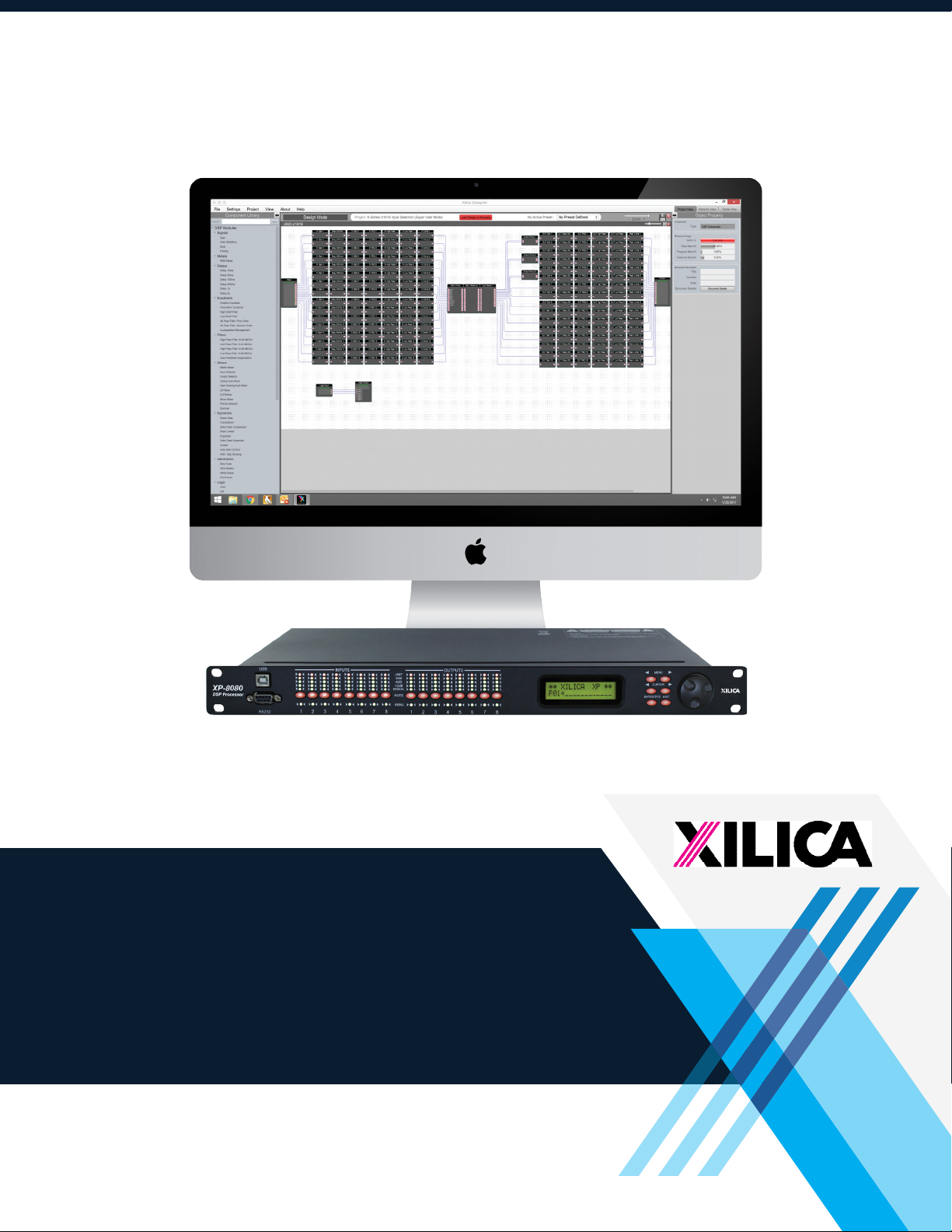
Install XConsole
The XConsole software provides optimum configuration of XD and XP Series processors.
Windows Installation
System Requirements
PC computer with a processor 1GHz or higher
Windows 7 or higher
500MB of available space
1GB graphics card
4GB RAM
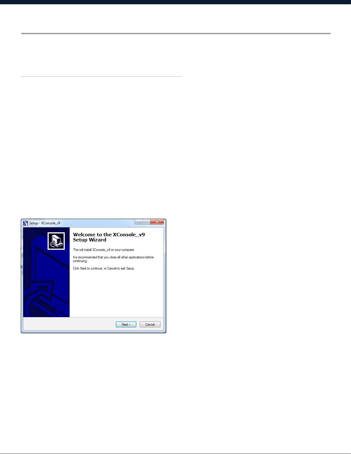
1. Download the latest version of XConsole from the Xilica website (www.xilica.com).
2. Open the downloaded .zip file.
3. Then open the XConsoleSetup_v0904.exe file.
4. An installation window will appear. Click Install to continue.
5. Allow the program to complete the installation process. This may take a several minutes.
6. When complete, Windows will ask for permission to allow firewall access. The suggested
setting is to allow XConsole to communicate in Private networks, such as home or work.
Allow access to public networks at your own discretion. Check the appropriate boxes, then
click Allow Access to finish.
7. XConsole is now installed.
8
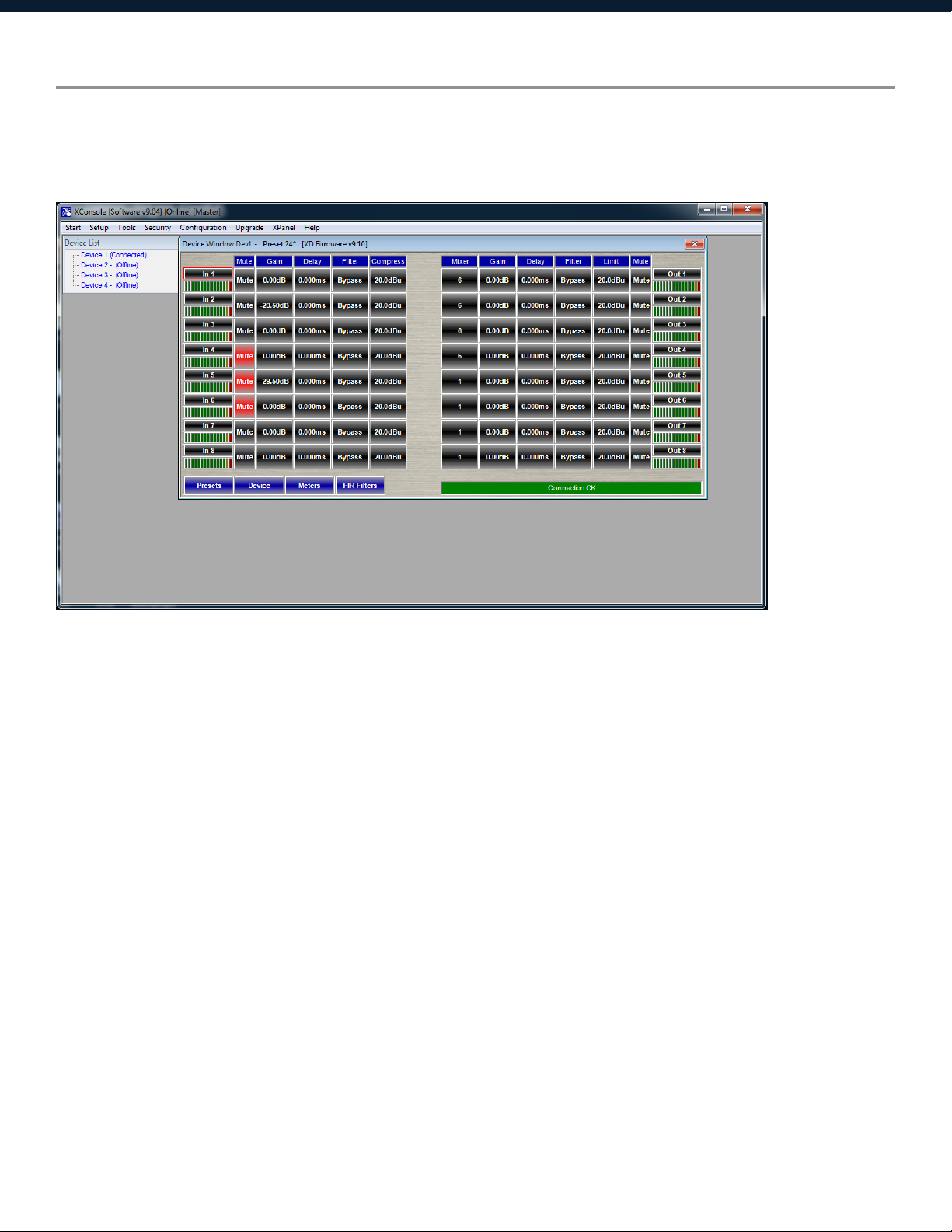
Launch XConsole
Locate the XConsole application on your Desktop or Applications folder.
Double click the application to launch the software.
Devices will display as a list on the left. Double click a device to open the device parameters.
9

Connection Troubleshoot
Please make sure that you are using the latest version of XConsole (v9.04).
For serial port/USB,
1. Open up the XConsole software.
2. Under the Setup tab at the top, select Port Connection.
3. A window will appear. Click on Device Manager.
4. Under Ports (COM & LPT), a Silicon Labs device will display.
If this is not displayed, try reconnecting the device (Disconnect and reconnect cable).
5. Please note the COM port of the device.
6. Navigate back to the Connection Setup window in XConsole and change the COM Port to the
COM Port # that was listed in Device Manager. Make sure that the Online box is checked. Then
click OK.
7. Restart XConsole and the device will now be connected.
In addition, the COM port has to be COM1 to COM8. To check if there is another software
running taking the COM port:
1. Open Terminal (Either click Command Prompt in XConsole or type Command at the Windows
start button Search programs and files area.
2. Close XConsole if it is opened.
3. Type Mode COM# where COM# is the Com Port# shown in Device Manager for Silabs.
If the port is available, it will show the serial port settings. (Don’t worry about the values, they
are not important.) If it says it is unavailable, then some software is taking up the port.
If the port is available, then set this port number in XConsole. The device should connect
successfully.
If the device is still not connecting, try assigning an manual static IP Address to the device. Please
note that this connection is done via Ethernet Cat5 cable.
10

Cat5 Ethernet connection
X Series IP Address can be configured on the front panel of the device or in the software.
1. On the front panel of the device, click the Enter button to enter the System menu.
2. Use the Menu arrows to navigate to the Ethernet menu.
The device IP Address can be viewed. To configure the device network settings, use the cursor
arrows and jog wheel to change the values.
3. Click Enter to save changes.
To view the IP address in XConsole,
1. Open XConsole.
2. Double click the connected device in the Device list. The device window will pop up.
3. Select the Device button located at the bottom left of the window. The device IP Address and
network settings are displayed.
11

Firmware Upgrade
Please note that using an older version of software with a newer firmware or newer software with
an older firmware will work but some of the features may not be available and bugs could exist.
We recommend upgrading the software and firmware to the latest versions.
Before you begin, check your software and firmware versions.
The device firmware version can be found on the front panel of the device. Upon boot up of
the device, the current device firmware version will briefly display on the front panel or enter the
System menu using the Enter key and navigate to the Information tab to view the current device
firmware.
To view the current software version, click on the About tab at the top of the software.
Firmware Upgrade Procedure:
Save any design files from the device onto your computer as all programmed data on the device
will be erased during the upgrade process. After the firmware upgrade is completed, the design
file can be loaded back into your device.
1. The device must be online and connected via USB or RS232 in order to perform a firmware
upgrade.
2. Download the latest firmware version for your device from the Xilica website (www.xilica.com).
3. Select the device you would like to upgrade. At the top of the software, select Upgrade >
Firmware. Make sure your device data is saved before proceeding.
Click Yes to continue.
Navigate to the file in which you downloaded the new Firmware file. Click Open.
12

The green status bar in the device window will display the Firmware Upgrade process. This may
take several minutes. DO NOT POWER OFF THE DEVICE. Powering off the device during a Firm-
ware Upgrade can result in a complete corruption of the processor.
Once the Firmware file has completed, the device will need to be manually switched Off and On
again. The software will also need to be rebooted.
13

Export/Import Files and Going Online
To load device settings from the computer to the device, or save settings from the device to the
computer,
1. Open the device parameters.
2. Click Preset located at the bottom left of the window.
3. There are three options:
Transfer Presets from PC to Device.
Transfer Presets from Device to PC.
Presets within Device only.
Select an option and click Proceed.
It is recommended to back up project files to an external location.
Saved project files will have a .xdat extension at the end of the file name.
14

Navigate Front Panel
Upon powering up the unit, the unit will start up and display the device model and firmware
version.
***** XILICA -4080 *****
-4080 v9.00B
Once initialized, the device screen will display the current program number and program name
assigned to the unit.
***** XILICA -4080 *****
P01*
If the program number ends with *, it means that no program is assigned, the last data before
previous power down is recalled instead.
Channel Menus
Channel Linking
While holding down the <<Menu or Menu>> button, more than one channel from the same input
or output group can be selected to link the channels together. The green LEDs below the for the
mute buttons are lit for the linked channels.
Any modification of the data will be applied to all linked channels. To cancel linking, simply
deselect the desired channel while holding the <<Menu or Menu>> buttons, or press the Exit key
to deselect all channels.
When a channel(s) is selected, the front panel menu will display the settings.
Use the Menu buttons to navigate menus, Cursor buttons to navigate parameters, enter to save to
settings and exit to close the menu.
15

Input microphone gain (Only available for XP 2040-M, XP 4080-M and XP 8080-M models)
I1: _______ Mic
LEVEL: 0dB
LEVEL The level (or gain) ranges from 0dB to +45dB in 3dB steps. This level will only have
an affect on the input channel when Mic input is selected from the system menu.
Input/Output Signal
I1: _______ Signal
LEVEL: 0.00dB
I1: _______ Signal
POL: +
I1: _______ Signal
DELAY: 000.000ms
LEVEL The level (or gain) ranges from -40dB to +15dB in 0.25dB steps.
POL The polarity (or phase) can be normal (+) or inverted (-)
DELAY The maximum delay permitted is 62400 samples. Each sample is approximately
10us (1/96k). The equivalent delay time is displayed to the right in parenthesis. The
delay time unit can be set to ms, ft or m in the System menu.
16

Input/Output Equalizers
I1: _______ EQ1
EQ#: 1
I1: _______ EQ1
BYPASS: Off
I1: _______ EQ1
TYPE: PEQ
I1: _______ EQ1
FREQ: 1000Hz
I1: _______ EQ1
BW:0.33 Q=4.36
I1: _______ EQ1
DEG: 15.5 deg
I1: _______ EQ1
LEVEL: 0.00dB
EQ# The level (or gain) ranges from -40dB to +15dB in 0.25dB steps.
BYPASS The polarity (or phase) can be normal (+) or inverted (-)
TYPE The maximum delay permitted is 62400 samples. Each sample is approximately
10us (1/96k). The equivalent delay time is displayed to the right in parenthesis. The
delay time unit can be set to ms, ft or m in the System menu.
FREQ The EQ centre frequency ranges from 20Hz to 30kHz in either 1Hz steps or 1/36
octave steps. The frequency steps can be selected in the System Menu.
BW The EQ bandwidth ranges from 0.02 to 3.61 octaves in steps of 0.01 octave. The
equivalent Q value is automatically shown besides the octave value.
DEG For first degree all-pass (AP-1) filter, the bandwidth will set the phase shift at the
centre frequency. The phase shift is gradually changed from 180 degrees above the
centre frequency to the specified value.
LVL The EQ level (or gain) ranges from -30dB to +15dB in 0.25dB steps.
17

Input Graphic Equalizer
I1: _______ GEQ1
GEQ#: 1 f=20
I1: _______ GEQ1
LEVEL: 0.00dB
I1: _______ GEQ1
BYPASS: Off
GEQ# The graphic equalizer has 31 bands of equalization from 20Hz to 20kHz. This control
selects one of the 31 available bands. The frequency corresponding to each band is
also shown.
LEVEL The GEQ level (or gain) ranges from -30dB to +15dB in 0.25dB steps.
BYPASS This control will un-bypass (Off) or bypass (On) the entire GEQ for this channel.
18

Input/Output Crossover
01: _______ XOver
TYPL: Off
01: _______ XOver
FRQL: 1000Hz
01: _______ XOver
SLPL: 24dB
01: _______ XOver
TYPH: Off
01: _______ XOver
FRQH: 1000Hz
01: _______ XOver
SLPH: 24dB
TYPL The three available filter types for the low frequency crossover point (high pass) are:
Butterworth, Linkwitz-Riley or Bessel.
FRQL The filter cut-off frequency for the low frequency crossover point (high pass) ranges
from 20Hz to 30kHz in either 1Hz steps or 1/36 octave steps. The frequency steps
can be selected in the System menu.
SLPL The filter slope for low frequency crossover point (high pass) ranges from 6 to
48dB/octave. If the selected filter type is Linkwitz-Riley, the available slopes are 12,
24, 36 or 48dB/octave only.
TYPH The three available filter types for the high frequency crossover point (low pass) are:
Butterworth, Linkwitz-Riley or Bessel.
FRQH The filter cut -off frequency for the high frequency crossover point (low pass) ranges
from 20Hz to 30kHz in either 1Hz steps or 1/36 octave steps. The frequency steps
can be selected in either the System menu.
SLPH The filter slope for high frequency crossover point (low pass) ranges from 6 to
48dB/octave. If the selected filter type is Linkwitz-Riley, the available slopes are 12,
24, 36 or 48dB/octave only.
19

Input Compressor
01: _______ Comp
THRESH: +20.0dB
01: _______ Comp
ATTACK: 10ms
01: _______ Comp
RELEASE: 8XAtck
01: _______ Comp
RATIO: 1:1
THRESH The compressor threshold ranges from -20dBu to +20dBu in 0.5dB steps.
ATTACK The compressor attack time ranges from 0.3ms to 1ms in 0.1ms steps, then ranges
from 1ms to 100ms in 1ms steps.
RELEASE The compressor release time can be set at 2X, 4X, 8X, 16X, or 32X the attack time.
RATIO The compressor ratio is the slope in which the signal is compressed. It ranges from
1:1 to 1:40.
20

Input/Output Channel Name
I1: _______ Name
NAME:________
NAME A six character name can be assigned to each channel.
Output Limiter
01: _______ Limit
THRESH: +20.0dB
01: _______ Limit
ATTACK: 10ms
01: _______ Limit
RELEASE: 8XAtck
THRESH A limiter threshold ranges from -20dBu to +20dBu in 0.5dB steps.
ATTACK The limiter attack time ranges from 0.3ms to 1ms in 0.1ms steps, then ranges from
1ms to 100ms in 1ms steps.
RELEASE The limiter release time can be set at 2X, 4X, 8X, 16X, or 32X the attack time.
21

Output Source
I1: _______ Source
IN1: Off
IN1-8 This sets the input channel source for the current output channel. It can be used to
mix the input source (in dB) or disable it (Off). If more than one input sources are
enabled, they will be added together as the source for the current output channel.
(5-8 available for 8080 model only)
22

System Menu
The System menu allows the user to control and change parameters that are related to the system
behaviour and general operation.
To access the system menu,
Make sure you are first in the main menu. (Press the Exit button to return to the main menu any
time). Press the Enter/Sys key.
Preset Recall
SYSTEM Recall
P:1 ___________
The has a built-in non-volatile memory that can store up to 30 different preset set-ups.
P This control selects which program to recall from the non-volatile memory. The
program name is displayed to the right of the program #.
23

Preset Store
SYSTEM Store
P:1
SYSTEM Store
NAM: ____________
The has a built-in non-volatile memory that can store up to 30 different program (or preset) setups. A program can be stored using this menu. The old program with the same program number
will be replaced. Once the program is stored in the flash memory, it can be recalled at a later
time, even after power down.
P This control selects which location in the non-volatile memory to save the program
to.
NAM A descriptive name of up to twelve characters can be assigned to each program.
Mic Pre-amps
SYSTEM Mic/L
IN1: Line
An optional microphone preamp can be added to the series. The user can select line input or
mic input from this menu. (Only available for 2040-M, 4080-M, 8080-M models only. Applies to
phantom power as well.)
IN1-8 The user can choose between Line input or Mic input/ For Mic input, the input will
receive a 30dB gain. Each input channel can be selected individually. (Input 5-8 only
available for 8080 model. Applies to Phantom power as well.)
24

Phantom Power
SYSTEM Phantm
IN1: On
The optional microphone pre-amp also comes with Phantom power, which can also be enabled
or disabled from this menu.
IN1-8 A 48V DC voltage can be supplied to external microphone when the Phantom
power is enabled. Phantom power cannot be enabled individually for each input
channel. All Mic input channels will automatically receive at 48V DC voltage. This
will not affect Line input since they are disconnected physically.
Copy Channels
SYSTEM Copy
Source: In1
SYSTEM Copy
Target: In2
Copy channels from the source to the target. When the source and targets are both inputs and
outputs, all audio parameters will be copied. When the Source or the Target is an input while the
other is an output, only the Level, Polarity, Delay, EQ, Crossover, and Channel name are copied.
SOURCE This is the channel to be copied from.
TARGET This is the channel to be copied to.
25

General Settings
SYSTEM Generl
FREQ MODE: All
SYSTEM Generl
DELAY UNIT: ms
Copy channels from the source to the target. When the source and targets are both inputs and
outputs, all audio parameters will be copied. When the Source or the Target is an input while the
other is an output, only the Level, Polarity, Delay, EQ, Crossover, and Channel name are copied.
FREQ
MODE
DELAY
This changes the frequency control mode for EQ and crossover filters. It can be 36
steps/octave or All frequencies (1Hz resolution).
This sets the time unit for input and output delay to ms, ft, or m.
UNIT
Ethernet Settings
SYSTEM Eth-IP
:255.255.255.254
SYSTEM Eth-GW
:255.255.255.255
SYSTEM Eth-SM
:255.255.255.255
Eth-IP A unique IP address should be assigned to each unit in the network.
Eth-GW The gateway address of the network. Usually this should be the IP address of your
router/switch/hub address.
Eth-SM This sets the subnet mask used by your network.
26

Communication Settings
SYSTEM Comm
DEVICE ID: 1
SYSTEM Comm
BAUD RATE: 115200
SYSTEM Comm
NETWORK ID: 0
NOTE: The user must power cycle the unit for this setting to take effect.
DEVICE ID This control assigns a device ID from 1 to 16 to the unit.
BAUD RATE Sets the baud rate of the serial communication. XConsole uses a Baud rate of
115200. This should be left unchanged for most users.
NETWORK IDThis control assigns a network ID from 0 to 60000 to the unit. The ID is used for
future network expansion only. Please leave this at 0.
Security Lock and Unlock
SYSTEM Secure
PASSWORD:________
The password is four characters in length. The factory default of a new unit does not require a
password. The device can be protected for unauthorized parameters and/or system abuse. The
security settings can be controlled and stored in the device with the XConsole GUI only. When
the correct password is entered in the device, all the locks are disabled. After re-entering the
password or power cycling the device, the locks are automatically enabled again.
27

Factory Settings
SYSTEM Reset
CURRENT: Yes
CURRENT This resets all the current parameters back to factory default settings only, while
stored presets and system settings stay untouched.
ISO Settings
SYSTEM ISO
THRESHOLD: 102
SYSTEM ISO
BYPASS: On
This internal system optimizer reduces ground floor noise if no signal is present. If unwanted
noise gate effects are audible at low sound levels, it can be switched to bypass mode
INFO
SYSTEM Info
NAM: ___________
SYSTEM Info
FIRMWARE: v9.00
SYSTEM Info
CODE: 11110000
This menu displays the device name, firmware version and security code.
When no password is set, the factory default code is 11110000. When another combination of
characters is displayed, a password is set in the device and certain functions are disabled for the
user to modify.
28

Quick Reference
Parameters
Mic level Mic LEVEL 0 +45 3 dB
Level Signal LEVEL -40 +15 0.25 dB
Polarity Signal POL +/ -
Delay Signal DELAY 0 62400 1 10us steps
EQ number EQ EQ# 1 8 1
EQ bypass EQ BYPASS Off/On
EQ type EQ TYPE PEQ / Lo-Shf / Hi-Shf / AP-1 / AP-2
EQ level EQ LEVEL -30 +15 0.25 dB
EQ frequency EQ FREQ 20 30,000 1 Hz
EQ bandwidth EQ BW 0.02 3.61 0.01 Octave
GEQ number GEQ GEQ# 1 31 1
GEQ level GEQ LEVEL -30 +15 0.25 dB
GEQ bypass GEQ BYPASS Off/On
XOver low type XOver FTRL Off / Butterworth / Linkwitz-Riley / Bessel
XOver low freq XOver FRQL 20 30,000 1 Hz
XOver low slope XOver SLPL 6 48 6 dB/octave
XOver high type XOver FTRH Off / Butterworth / Linkwitz-Riley / Bessel
XOver high freq XOver FRQH 20 30,000 1 Hz
XOver high slope XOver SLPH 6 48 6 dB/octave
Menu
<<Menu>>
Field
<<Cursor>>
Min Max Steps Units
Compressor threshold Comp THRESH -20 +20 0.5 dBu
Compressor attack Comp ATTACK 0.3 100 0.1/1 ms
Compressor release Comp RELEASE 2 / 4 / 8 / 16 / 32X attack time
Compressor ratio Comp RATIO 1:1 to 1:40
Limiter threshold Limit THRESH -20 +20 0.5 dBu
Limiter attack Limit ATTACK 0.3 100 0.1/1 ms
Limiter release Limit RELEASE 2 / 4 / 8 /16 / 32X attack time
Source select Source
Channel name Name NAME 6 characters
1, 2, 3, 4, 5, 6,
7, 8
Off +15 0.25 dB
29

Customer Support
If you’d like to contact us regarding product support or
technical designs, email support@xilica.com and we’ll
connect you with a solutions engineer Alternatively, if
you’d like to speak to someone, you can call the following
numbers for immediate assistance:
International: +1 905 770-0055
US Toll Free: +1 877 767-0234
Europe: +31 29940-1100
China & Hong Kong SAR: +852 2604-9382
www.xilica.com
Version 3.0
30
 Loading...