

USER GUIDE
PoE & Optical Transmission
POE08 S eries
Stateme nt
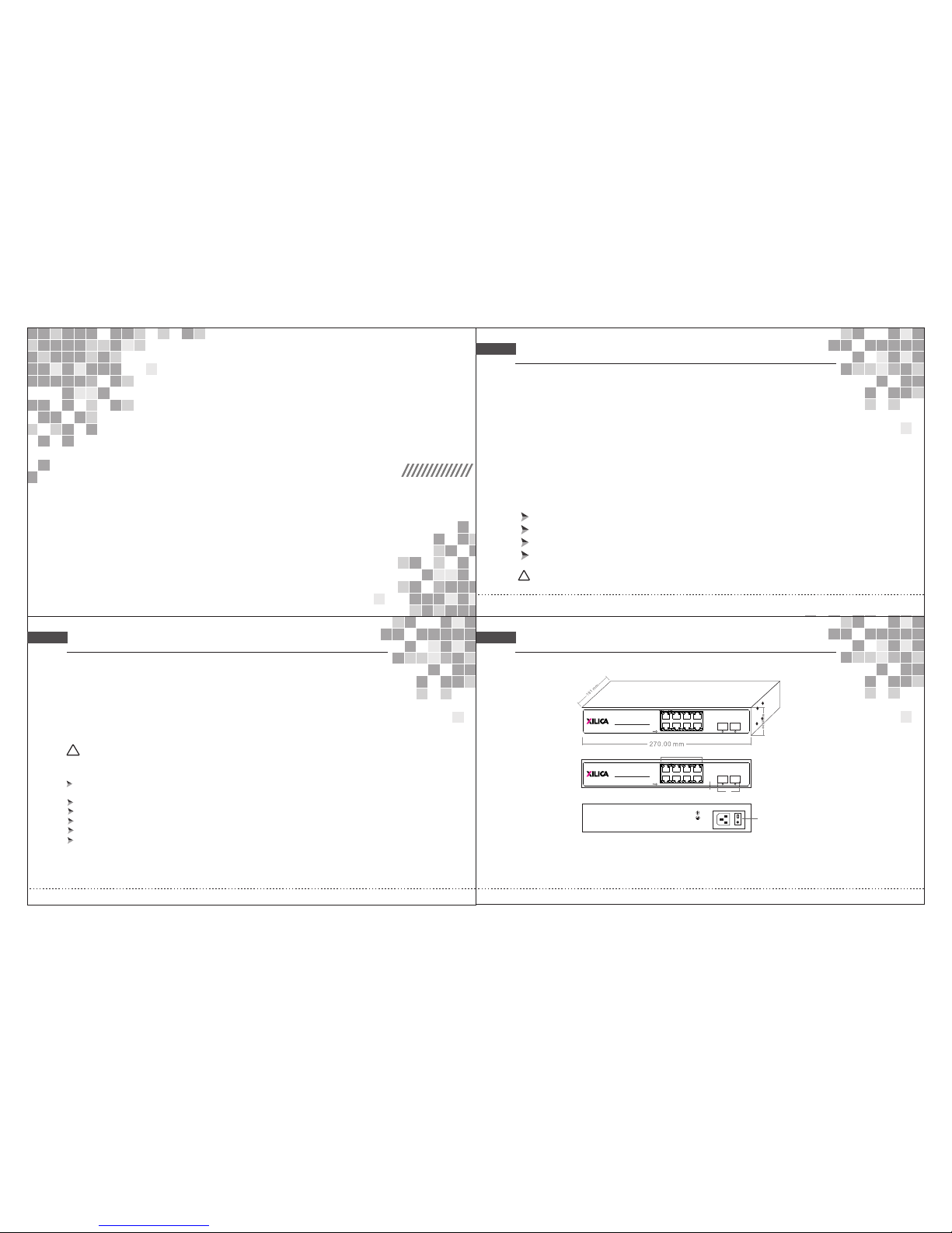
Techni cal Struc ture and Po rt Desc ri ption
Cop yrigh t @ 2002- 2018 Ou r compa ny,All R ights R eserv ed
!
Pac king Li st
Ple ase kin dly che ck the fo llowi ng item s:
1 xPo E switc h
Pow er Cabl e
Mou nting K its
1x Us er Guid e/ Warra nty Car d
Note
If an y short age or da mage fo und, pl ease co ntact u s in time .
Thi s docum ent con tains p ropri etary i nform ation t hat is pr otect ed by cop yrigh t. No par t of this d ocume nt
may b e repro duced , trans mitte d, tran scrib ed, sto red in a re triev al syst em, or tr ansla ted int o any lan guage ,
in an y form or b yany me ans, el ectro nic, me chani cal, ma gneti c, opti cal, ch emica l, manu al or oth erwis e
wit hout th e prior w ritte n permi ssion o f Our com pany.
The i nform ation a nd prod uct spe cific ation s withi n this do cumen t are sub ject to c hange a t any tim e, with out
not ice and w ithou t obli- gatio n to noti fy any pe rson of s uch cha nge.
Product O verview
POE 08 seri es has 8x R j45 Eth ernet p orts th at comp liant w ith 10/ 100/1 000
Bas eT, 802.3 af(Po E)and80 2.3at (PoE+ ), and 2x g igabi t SFP port s. This s witch c an offe r power o ver
Eth ernet t o netwo rk weat herpr oof IP ca mera wi th wipe rs and he ater, hi gh perf orman ce wire less AP,
ind ustri al VoIP ph one or ot her PoE s uppor ted equ ipmen ts, fle xible f or appl icati ons. SF P fiber op tic
por t trans missi on dist ance ca n be up to 12 0KM, wi th high r esist ance to e lectr omagn etic
int erfer ence.
IEE E802. 3 10BAS E-T Ethe rnet, I EEE80 2.3u 10 0BASE -TX fas t Ether net, IE EE802 .3ab
100 0 BASE- T gigabi t Ether net;
Sup port IE EE802 .3X , and B ackpr essur e full/ h alf dup lex flo w contr ol;
Note
Features
!
The p roduc t ‘Swit ch’ ment ioned i n the man ual, if w ithou t a speci al requ est, it i s refer ring to P OE08
PoE s witch , PoE swi tch or sw itch in s hort in b elow.
Pro duct In trodu ction
Has 1 0/100 /1000 M auto- sensi ng Rj45 p orts, s uppor ting Po E;
All p orts su pport a uto MDI /MDIX ;
Max p ort pow er is up to 1 5.4W( af) or 30 W(at) ;
Onl y feed po wer to IE EE802 .3af/ IEEE8 02.3a t compl iant de vices ;
A
B
C
AC/IN 10 0-240 V
D
A. Po E P ort
C. SFP ports
B. CONSOLE Port
D. 10 0-240 VAC, 50/6 0Hz
G9
G10
F F
G1
G3
G5 G7
G2 G4 G6 G8
POE 08
Power over Ethernet Switch
8 Ports 10/100/10 00Mbp s + 2G SFP PoE S witch
G9
G10
F F
G1
G3
G5 G7
G2 G4 G6 G8
POE 08
Power over Ethernet Switch
8 Ports 10/100/10 00Mbp s + 2G SFP PoE S witch
Panel Des criptio n
Install ation Gui de
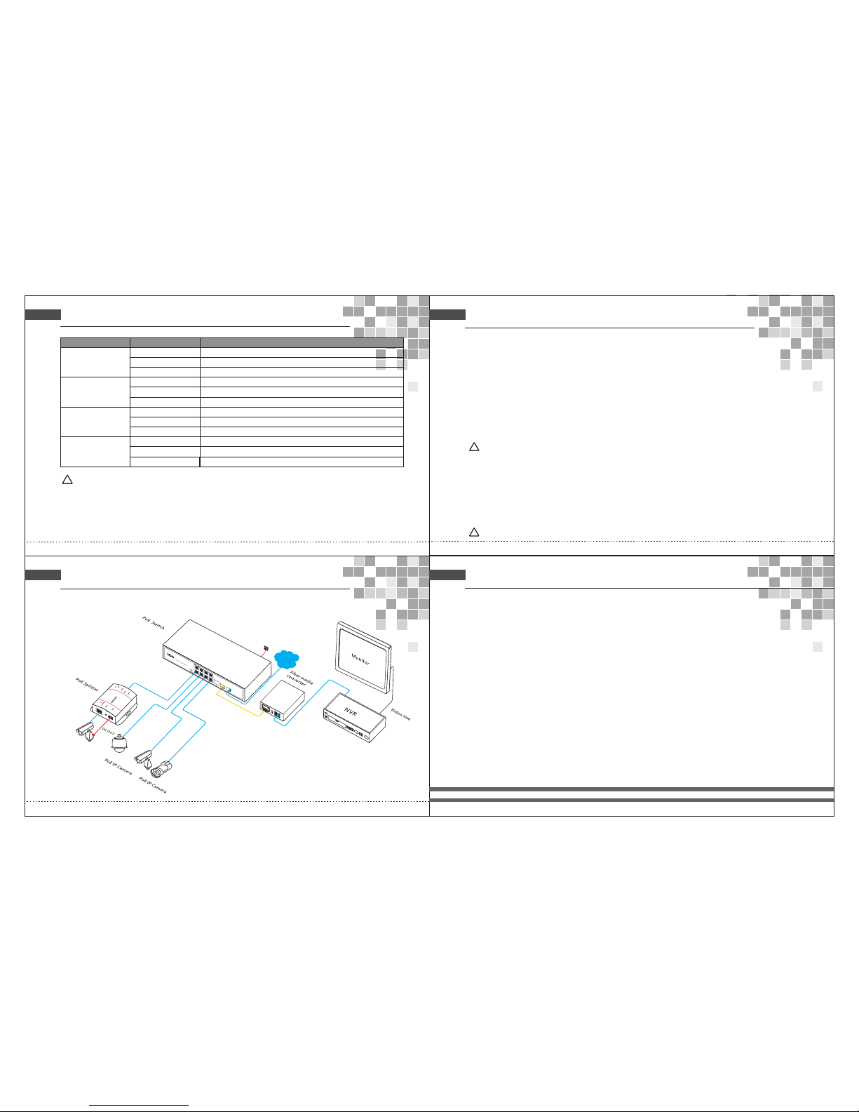
Application Con ne ction Diagram
Models De scripti on
!
(Pl ease in stall t o the sup porte d devic es)
Installat ion
Ple ase con firm th e follo wing th ings be fore in stall ation :
1. If t he POE po rt meet s the pow er requ ireme nt of the c onnec ting de vices .
2. If t he POE st andar d requi remen t and pow er supp ly matc hes wit h the pow er rece iving d evice
(1/ 2+、3/6- ( End -sp an)/ 4/ 5+、7/8- (Mid- span) )
3 .If t he outp ut powe r of the ma tched p ower ad apter i s compa tible w ith the s pecif icati on in the
lab el of the P OE swit ch
Ple ase ins tall th e POE swi tch acc ordin g to the fo llowi ng step s:
1. Put the PoE switch on the surface of a large and stable table, or professional installation rack mount.
2. Connect Positive, Minus and Earth terminals as indicators on the power adapter.
3. Connect the network devices to the POE switch port though network cable.
1.P lease d o not put h eavy pr oduct s on the PO E switc h, and pl ease en sure go od vent ilati on
env ironm ent for t he POE sw itch.
2.P lease c ut off th e power f irst be fore pl uggin g the pow er adap ter.
Power
Con nect th e power c able, p lug it in to powe r socke t, turn o n the pow er, then t he swit ch will a utoma tical ly
ini tiali ze, and L ED ligh ts stat us will d ispla y as foll owing :
1. Ex cept th e POE por t light s, all th e other l ights w ill go th rough t he proc ess of “o n-off -on-o ff”, whi ch
mea ns the sy stem re stora tion is s ucces sful.
2. Po wer LED r emain s lit.
If in itial izati on is inc onsis tent wi th the ab ove, pl ease ch eck the p ower.
Note
!
Note
Note:Ple ase con firm th at the al l PoE por ts of PD dev ices ar e compl ying wi th IEEE 802.3 af/at s tanda rd.
!
Pow er: 48 VD C (46 ~57 VDC), (More t han 50V DC reco mmend ed when u sed PoE + outpu t)
PoE P ort: Th e PoE por ts supp ort PoE f uncti on, whi ch can tr ansmi t data an d power s imult aneou sly if co nnect ed
mat ching d evice . The LED l ights o n the fro nt pane l can sho w worki ng stat us of eac h port.
Ind icato r
Sta tus
Des cript ion
Sys tem Indi cator :
SYS
Gre en LED Bl ink
Sys tem wor k as norm al (POE 33108 PFM onl y)
PoE I ndica tor: Po E
Lin k Indic ator: L ink
Gre en LED OF F Sy stem ab norma l or powe r off
Gre en LED ON
Con necte d PD devi ce, pow ering p roper ly
Gre en LED Bl ink Sho rt circ uit or cu rrent o verlo ad
Gre en LED OF F No co nnect ed PD or po wer off
Yello w LED ON
Dat a trans missi on prop erly
Yello w LED Bli nk
Con necti on is OK an d data is b eing se nt and re ceive d
Yello w LED OFF
No co nnect ed devi ce
Gre en LED ON
Gre en LED Bl ink
Gre en LED OF F
Dat a trans missi on prop erly
Con necti on is OK an d data is b eing se nt and re ceive d
No da ta conn ected
SFP U plink I ndica tor
Gre en LED ON
Sys tem wor k as norm al (POE 33108 PF only )
W
AN
W
id
e
Area Ne
t
w
ork
G9
G10
CONSOLE
F
F
115200,N,8,1
G1
G3
G5
G7
G2
G4
G6
G8
PoE08
Power
Non-P oE IP Came ra
C
a
t
.
5
e/6
C
at.5e /6
PoE (da ta+po wer)
POE08: Ethernet unmanaged PoE switch,8x 10/100/1000M RJ45,PoE ports+ 2x 100/1000M SFP slots,
1-
8 ports support PoE, IEEE 802.3af, RJ45 ports transmission distance, is 100 meters, transmission distance
of optic fiber port with SFP module can be up to 2-120KM.
Cat.5 e/6
POE 08
Power over Ethernet Switch
8 Ports 10/100/1000Mbps + 2G SFP PoE Switch
 Loading...