

Xilica Audio Design NEUTRINO series, NEUTRINO A1616-N, NEUTRINO A1616-ND User Manual
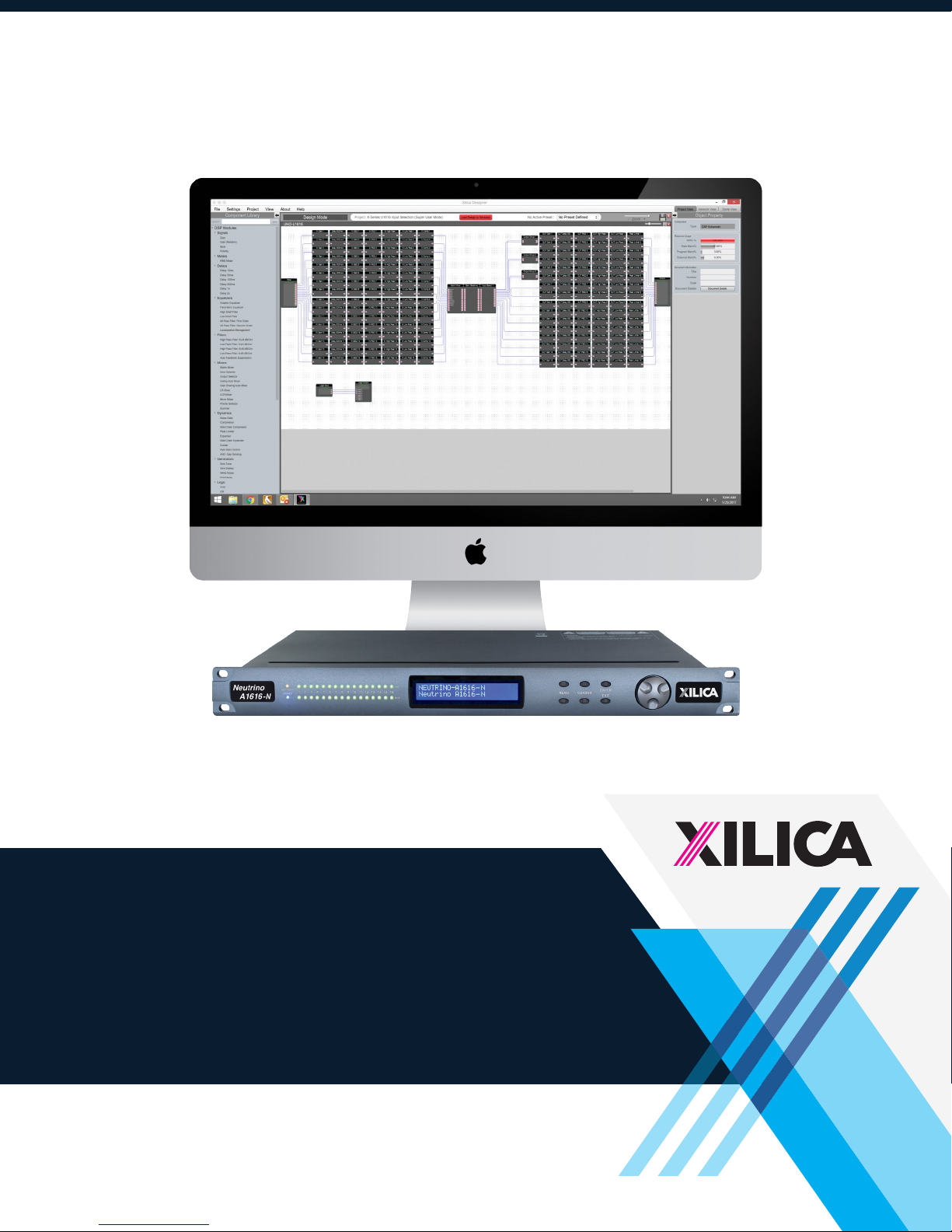
NEUTRINO SERIES
User Manual
1

Important Safety Information
1. READ THESE INSTRUCTIONS
All the safety and operating instructions should be read before the product is operated.
2. KEEP THESE INSTRUCTIONS
The safety and operating instructions should be retained for future reference.
3. HEED ALL WARNINGS
All warnings on the product and in the operating instructions should be adhered to.
4. FOLLOW ALL INSTRUCTIONS
All operating and use of instructions should be followed.
5. DO NOT USE THIS APPARATUS IN WATER.
Do not use the product near water. For example, near a bathtub, wash bowl, kitchen sink, or laundry tub, in a wet basement, or near a
swimming pool, and the like.
6. CLEAN ONLY WITH DRY CLOTH.
Unplug the unit from the wall outlet before cleaning.
7. DO NOT BLOCK ANY VENTILATION OPENINGS
Slots and openings in the cabinet back or bottom are provided for ventilation, to ensure reliable operation of the limit and to protect it from
overheating. These openings must not be blocked or covered. The openings should never be blocked by placing the product on a bed, sofa,
rug, or similar surface. This product should never be placed near or over a radiator or heat source. This product should not be placed in a
built-in installation such as a bookcase or rack unless proper ventilation is provided or the manufacturer’s instructions have been adhered to.
8. DO NOT INSTALL NEAR ANY HEAT SOURCES
This product should be situated away from heat sources such as radiators, stoves or other products (including amplifiers) that produces heat.
9. DO NOT DEFEAT THE SAFETY PURPOSE OF THE POLARIZED OR GROUNDING-TYPE PLUG
A polarized plug has two blades with one wider than the other. A grounding-type plug has two blades and a third grounding prong. The wide
blade or the third prongs are provided for your safety. If the provided plug does not fit into your outlet, consult an electrician for replacement
of the obsolete outlet.
10. PROTECT THE POWER CORD FROM BEING WALKED ON OR PINCHED PARTICULARLY AT PLUGS, CONVENIENCE RECEPTACLES,
AND THE POINT WHERE THEY EXIT FROM THE APPARATUS.
11. ONLY USE ATTACHMENTS/ACCESSORIES SPECIFIED BY THE MANUFACTURER.
12. USE ONLY WITH CART, STAND, TRIPOD, BRACKET, OR TABLE SPECIFIED BY THE MANUFACTURER, OR SOLD WITH THE APPARATUS.
WHEN A CART IS USED, USE WITH CAUTION WHEN MOVING THE CART/APPARATUS TO AVOID INJURY FROM TIP-OVER.
Do not place this unit on an unstable cart, stand, tripod, bracket, or table. The unit may fall, causing serious injury to someone, and serious
damage to the appliance. A unit and cart combination should be moved with care. Quick stops, excessive force, and uneven surfaces may
cause the product and cart combination to overturn.
13. UNPLUG THIS APPARATUS DURING LIGHTNING STORMS OR WHEN UNUSED FOR LONG PERIODS OF TIME.
For added protection for this unit during a lightning storm, or when it is left unattended and unused for long periods of time, unplug it from
the wall outlet and disconnect the antenna or cable system. This will prevent damage to the unit due to lightning and power surges.
14. REFER ALL SERVICING TO QUALIFIED PERSONNEL. SERVICING IS REQUIRED WHEN THE APPARATUS HAS BEEN DAMAGED IN ANY
WAY. SUCH AS, WHEN THE POWER SUPPLY CORD OR PLUG IS DAMAGED, LIQUID HAS BEEN SPILLED, OR OBJECTS HAVE FALLEN
INTO THE APPARATUS, THE APPARATUS HAS BEEN EXPOSED TO RAIN OR MOISTURE, DOES NOT OPERATE NORMALLY, OR HAS BEEN
DROPPED.
15. WARNING: TO REDUCE THE RISK OF FIRE OR ELECTRIC SHOCK, DO NOT EXPOSE THIS APPARATUS TO RAIN OR MOISTURE.
16. APPARATUS SHALL NOT BE EXPOSED TO DRIPPING OR SPLASHING AND NO OBJECTS FILLED WITH LIQUIDS, SUCH AS VASES,
SHALL BE PLACED ON THE APPARATUS.
2

Table of Contents
Labels and Descriptions
4-5
Technical Specifications 6
AES/EBU Pinout Information 7
Device Connectivity
8-9
Install Xilica Designer
Mac OS X Installation
Windows Installation
10
11
Launch Xilica Designer
Network View 12
Firmware Upgrade 13-15
Project View 16
Create a Design 17-21
Going Online 22-25
Contact and Support 26
3

Front Panel
3
1 42 5 76 8 9 11
1 Model Badge
2 Power
3 Network
4 Output
10
A badge displaying the device series and model name.
A blue LED light which indicates that the hardware device is powered
On. This LED light will flash when powering On the device or when
performing a firmware upgrade.
An orange LED light which indicates that a network cable is connected.
Each output channel has a dual color (Red or Green) LED light indicator.
Green LEDs indicate that the signal is present at -40dBu. Red LEDs
indicate analog clipping at +17dBu.
5 Input
6 LCD Display
7 Menu
8 Cursor
9 Exit
10 Enter
11 Jog Wheel
Each input channel has a dual color (Red or Green) LED light indicator.
Green LEDs indicate that the signal is present at -40dBu. Red LEDs
indicate analog clipping at +17dBu.
The LCD display shows device information and settings.
The Menu (Up and Down) buttons are used to scroll through the device
menus.
The Cursor (Up and Down) buttons are used to scroll through device
parameters.
The Exit buttons is used to exit out of menus and return to the home
screen.
The Enter button is used to confirm actions.
The Jog Wheel is used to adjust values.
4

Rear Panel
4 5 6*
1 Power switch
2 Power supply
3* AES/EBU
4 Ethernet
5 IP Reset
6* Dante™
7
Power ON/OFF the processor using this switch.
Insert the plug connector into the socket. Connect the cord into a 90240 VAC 50-60Hz power source.
Transport 8x8 AES/EBU digital audio channels over a DB-25 connector
(Tascam protocol). (Only available for ‘D’ models including, Neutrino-D,
ND models)
Connect the device to the network using a standard RJ45 (Ethernet)
cable.
A button used to reset the IP Address.
Digitally transport
over a standard RJ45 (Ethernet) cable. (Only available for ‘N’ models
including, Neutrino-N, ND and AEC-N models)
16x16 I/O of Dante network audio bi-directionally
81 92 3*
7 GPIO
8 Inputs
9 Outputs
Connect a twisted pair wire with an attached terminal block to send
GPIO control signals.
Input connections are established using Euro/Phoenix 3.5mm type
connectors. Neutrino has eight or sixteen switchable mic/line inputs
depending on the model.
Output connections are established using Euro/Phoenix 3.5mm type
connectors. Neutrino has eight or sixteen outputs depending on the
model.
5

Technical Specifications
Input impedance >10k Ohms
Output impedance 50 Ohms
Maximum level +20dBu
Mic/Line Mic (+40dB gain)/Line (0dB)
Type Electronically balanced w/ 48V Phantom power
Frequency response +/-0.15dB (20 to 20kHz)
Dynamic range 110dB typ (unweighted)
CMRR >50dB @ 1kHz
Crosstalk <-110dB @1kHz
Distortion 0.002% (1kHz @ +4dBu)
Processor 40-bit floating point
Sampling rate 48kHz
Propagation delay 3ms (AEC: 11ms)
Analog converters High-performance 24-bit
Connectors Euro/Phoenix plug-in 3.5mm connectors (included), RJ45 Ethernet,
IEC power socket
Power 90-240 VAC (50-60Hz)
Mounting 1RU, with vent between units
Dimensions 19”x1.75”x9” (483x44x229mm)
Weight 11lbs / 5kg
Warranty 2 years, parts and labor
6
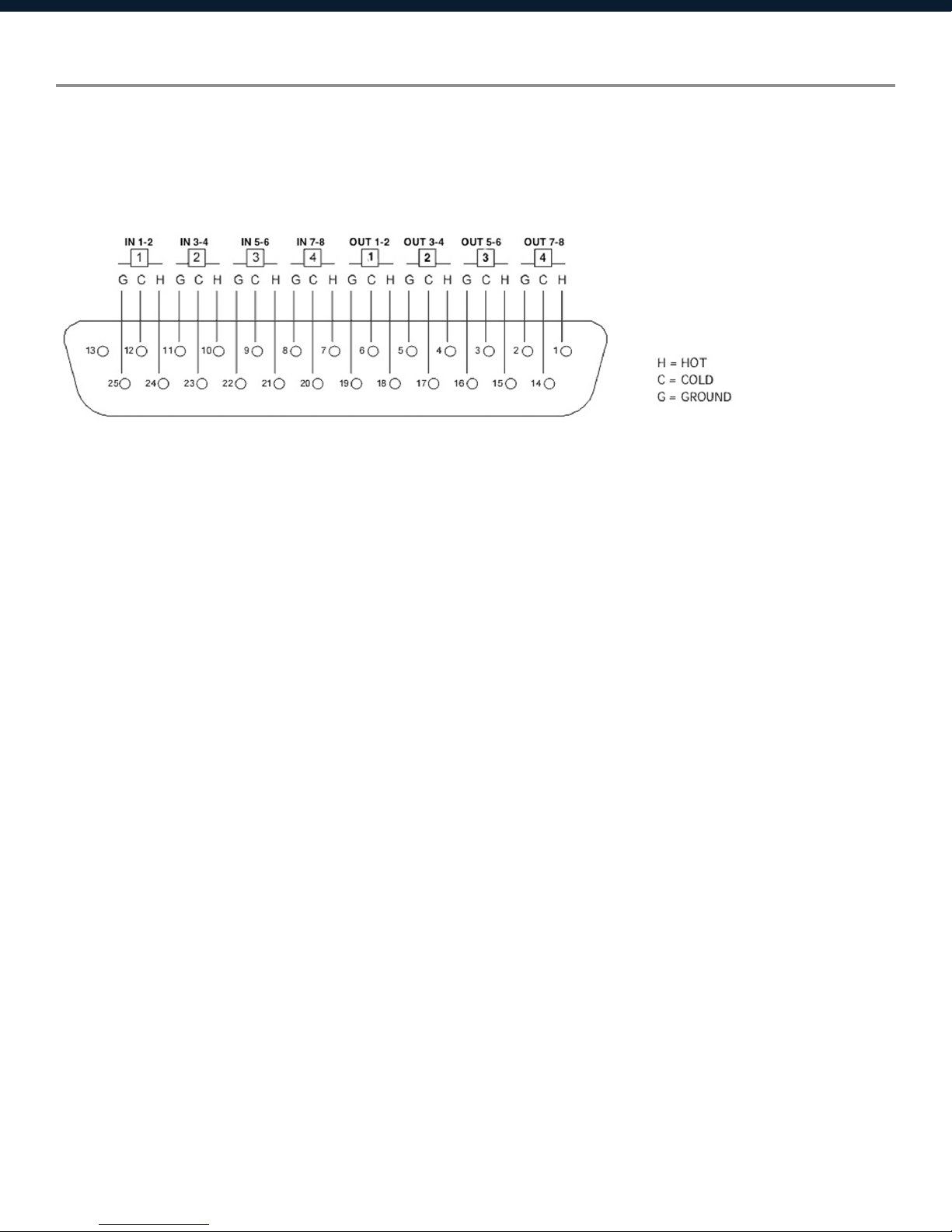
AES/EBU Pinout Information
Neutrino-D models with AES/EBU digital audio use a DB-25 connector with the original TASCAM
protocol. The pinout details are as follows:
AES/EBU DB-25 to DB-25 connections require a different pinout in the cable. AES/EBU must ip the
connections so that pins 12, 24 and 25 will wind up on the other end of the cable at pins 6, 18 and
19 respectively. (Digital out must feed digital in).
7

Device Connectivity
Xilica processors and control devices run on a network based infrastructure and are set up
and controlled by a host computer using the Xilica Designer software.
What’s in the Box
• Neutrinohardwaredevice
• 90-240VAC50-60Hzpowercable
• 3.5mmPhoenix/Eurotypeterminalblockconnectors
What you need to Provide
• Computer
• Networkinterface(Router,PoEswitch)
A router is used for IP assignment and easy connectivity to computer and control devices.
A PoE switch is used for controllers if local power is not used.
•Ethernetcables
All wired connections use a standard RJ45 Cat 5/6 (Ethernet) connection.
Connecting Devices
A network connection can be made between the computer and processor using:
A) DHCP enabled Router or Server/Router combination (Recommended)
With DHCP enabled routers and servers, the processor will automatically obtain the IP
address upon power up and connection. When other Xilica wall controls will also be used, it is
recommended to use a router and PoE switch. This combo provides DHCP as well as power to the
wall controls. Linksys routers and Netgear switches are recommended.
B) A non-DHCP direct connection or indirect connection via an Ethernet switch
When the processor is connected directly to a computer or indirectly via a switch/hub and DHCP is
not available, the connection process is not automatic.
8
 Loading...