

XIIMUS 1024CTI, 512CTI, 2048CTI User Manual
XIIMUS R-GB-IR CL User Manual. Version 1.2
X I I M U S
MODELS: 512CTi, 1024CTi & 2048CTi
USER MANUAL
ver 1.2
18 October 2006
TVI Vision Oy reserves the right to change any information in this document without prior notice. TVI
Vision Oy will not take any responsibility for any damage caused by possible inaccuracies or faults in the
equipment. This document may not be copied without the written consent of the TVI Vision Oy. An unauthorised use or distribution of this document to a third party is prohibited.
18.10.2006

XIIMUS R-GB-IR CL User Manual. Version 1.2
DOCUMENT HISTORY
Version Date Author Description
0.1 2 Jun 2005 nr Modified from the respective RGB User Manual
0.2 29 Mar 2006 jjl Updates until App. B.
1.0 2 June 2006 nr & jjl First release
1.1 9 June 2006 nr Appendix C: Serial communications
Firmware updates:
D11 Æ D13 and D12 ÆD14
Read-out of temperature status
Time-out at RS-232 port
1.2 18 Oct 2006 jjl Appendix: Cooling Option.
Minor changes in wording.
© TVI Vision, 18 October 2006 page 2 ( 57 )

XIIMUS R-GB-IR CL User Manual. Version 1.2
DECLARATION OF CONFORMITY
AS DEFINED BY THE COUNCIL DIRECTIVE
89 / 336 / EEC
EMC (ELECTROMAGNETIC COMPATIBILITY)
WE HEREWITH DECLARE THAT THIS PRODUCT
COMPLIES WITH THE FOLLOWING PROVISIONS APPLYING TO IT.
Emission CISPR 22 (1997)
Immunity IEC 61000-6-2 (1999)
APPLICABLE PATENTS:
FI 97264
US 6,476,870
EP 0 788 709
CA 2,203,835
JP 3626998
© TVI Vision, 18 October 2006 page 3 ( 57 )

XIIMUS R-GB-IR CL User Manual. Version 1.2
TABLE OF CONTENTS
1. INTRODUCTION............................................................................................................5
2. PRECAUTIONS ............................................................................................................. 6
3. CAMERA OVERVIEW ................................................................................................... 8
3.1 COLOUR SEPARATION ................................................................................................... 8
3.2 CAMERA OPERATION..................................................................................................... 8
4. PROCESSING OF CCD OUTPUT............................................................................... 11
4.1 ANALOGUE VIDEO PATH ............................................................................................... 11
4.2 PIXEL CORRECTION UNIT.............................................................................................. 12
4.2.1 Description......................................................................................................... 12
4.2.2 Data order.......................................................................................................... 12
4.2.3 Correction algorithm.......................................................................................... 12
4.2.4 Implementation of the correction....................................................................... 14
5. CAMERA INTERFACE................................................................................................ 16
5.1 POWER INPUT ............................................................................................................. 16
5.2 LED INDICATORS ........................................................................................................ 17
5.3 DATA CONNECTOR ...................................................................................................... 18
5.4 RS-232 PORT ............................................................................................................. 19
5.5 PROGRAMMING CONNECTOR........................................................................................ 19
6. MECHANICAL STRUCTURE......................................................................................20
6.1 MECHANICAL DIMENSIONS AND MOUNTING OF THE CAMERA ........................................... 20
6.2 ATTACHMENT FOR OPTICS ........................................................................................... 20
7. OPTICAL CONSIDERATIONS....................................................................................21
7.1 SPECTRAL RESPONSE ................................................................................................. 21
7.2 SELECTION OF OPTICS ................................................................................................. 22
7.2.1 Modulation transfer function.............................................................................. 22
7.2.2 Resolution and field of view............................................................................... 23
7.2.3 Depth of field and working aperture .................................................................. 24
8. LIGHTING ....................................................................................................................25
8.1 SPECTRAL RADIANCE AND COLOUR TEMPERATURE ........................................................ 25
8.2 UNIFORMITY OF LIGHTING ............................................................................................ 25
9. TECHNICAL SPECIFICATIONS ................................................................................. 27
10. APPENDIXES .............................................................................................................. 29
10.1 APPENDIX A: CAMERA LINK
®
OUTPUT BIT PORT ASSIGNMENTS ................................ 30
10.2 APPENDIX B: TIMING DIAGRAMS ........................................................................ 31
10.2.1 B1: Parallel colour channels output modes.......................................................31
10.2.2 B2: Multiplexed colour channels output modes................................................. 32
10.3 APPENDIX C: SERIAL COMMUNICATIONS ............................................................ 33
10.4 APPENDIX D: MODEL NUMBERS FOR XIIMUS CAMERAS ..................................... 51
10.5 APPENDIX E: ORDERING CODES FOR XIIMUS CAMERAS..................................... 52
10.6 APPENDIX F: APPLICATION NOTES ..................................................................... 54
10.6.1 TVI-AN701: Using encoder inputs for triggering ...............................................54
10.7 APPENDIX G: COOLING OPTION ......................................................................... 56
© TVI Vision, 18 October 2006 page 4 ( 57 )

XIIMUS R-GB-IR CL User Manual. Version 1.2
1. INTRODUCTION
The XIIMUS is a rugged, high performance, fully digital colour line scan camera for demanding industrial applications. It utilises a high accuracy 3-CCD architecture with a choice
of either 512, 1024 or 2048 pixel sensors at speeds up to 40 million pixels per second per
colour channel. The TVI Vision XIIMUS cameras are optimised for high sensitivity and
precise colour recognition.
The applications for the XIIMUS cameras include:
• web inspection
• inspection of natural materials like food, wood, ore, minerals and lumber
• recycling
• quality control in printing processes
• texture recognition
CUSTOMER SUPPORT
If you need to contact the manufacturer directly, please send your questions preferably by
email to TVI Vision. They will be forwarded to the responsible persons, who will contact you
as soon as possible.
Email:
Fax: +358 9 7590 0319
Phone: +358 9 759 001
Address: Asentajankatu 3
00880 Helsinki
FINLAND
sales@tvivision.com
© TVI Vision, 18 October 2006 page 5 ( 57 )

XIIMUS R-GB-IR CL User Manual. Version 1.2
2. PRECAUTIONS
Read the manual
Please read the manual carefully before using the camera the first time.
Do not drop the camera
Handle the camera with care at all times, since it is a sensitive optical device. Do not drop the
camera and avoid mechanical shocks to the camera.
Keep foreign matter outside the camera
Do not spill liquids on the camera. The camera is not liquid or waterproof.
Do not drop any kind of objects or foreign material into the camera. Metallic objects might
cause short circuit and/or damage the optical assembly.
Cleaning
Keep the shade cap on the camera head when not used to avoid contaminating the prism.
The input surface of the prism is not shielded nor protected from the outside of the camera.
It is recommended that the camera is serviced by TVI Vision, if the front surface of the prism
is very dirty, since the surface area of the prism cannot be fully accessed from the front.
If there are small amounts of contaminants or dust on the prism surface, use a clean lint free
cotton swab or other non-abrasive medium dipped in acetone or pure alcohol to clean prism
surface. Shake excess solvent off before touching the surface of the prism to avoid streaking.
TVI Vision is not responsible for any scratches or damage inflicted by the customer to the
front surface of the prism.
To clean the exterior casing of the camera, use a soft, dry cloth. In case of severe stains use
a small amount of pure alcohol. Do not use isopropyl alcohol or acetone or other volatile solvents such as benzene or thinners.
Do not open the camera
Do not open the camera. In doing so, the warranty of the camera will expire immediately.
Only authorised service personnel may open the camera.
Ventilation
Allow sufficient air circulation around the camera. If this condition is not met the camera might
shut down during operation, because it is designed to do so in order to prevent damage to
the optical assemblies. Further increase of the temperature may damage the camera.
© TVI Vision, 18 October 2006 page 6 ( 57 )

XIIMUS R-GB-IR CL User Manual. Version 1.2
Storage
Do not store the camera in a temperature over + 55 ºC or 131 F. There is a permanent temperature indicator inside the camera, which is installed to ensure that if the camera is
damaged due to overheat, the warranty of the camera may be void.
Electromagnetic fields
Do not operate the camera in the vicinity of strong electromagnetic fields (above the requirements of CE conformity). This may cause erroneous operation of the camera.
Transporting
Preferably transport the camera in its original packaging. If the package is discarded, please
package with care in thick layer of soft, preferably anti-static material when transporting. Do
not use material that allows the camera to drop to the bottom of the package while transporting. Do not transport with an objective attached. Let the camera slowly reach the ambient
temperature after transportation before powering it up the first time.
© TVI Vision, 18 October 2006 page 7 ( 57 )
XIIMUS R-GB-IR CL User Manual. Version 1.2
T
3. CAMERA OVERVIEW
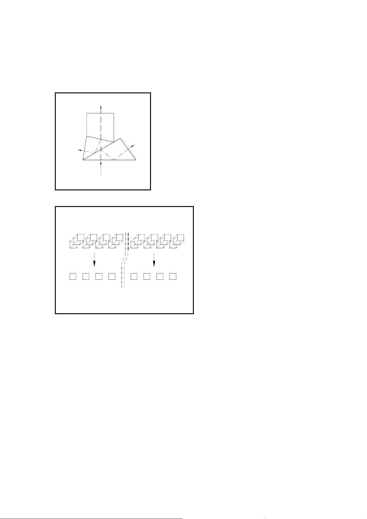
3.1 Colour Separation
INFRARED
RED
INCOMING LIGH
BLUEGREEN
3 x CCD
R-GB-IR colour line
Figure 3.2. Alignment of the CCD linear arrays.
The incoming light is separated into three, Infrared, Red
and Bluegreen, colour images by an R-GB-IR beam
splitter (figure 3.1). The spectral distribution of each
colour is standardised and well known. By attaching a
CCD to each of these colour outputs, it is possible to
measure the intensity of each colour image.
Figure 3.1 The R-GB-IR colour separation beam splitter.
The CCDs are aligned to each other to
get the perfect image of the three
measured colour components. All the
three CCDs see exactly the same area
of the target from same viewing angle,
IR
distance and at the same time.
R
GB
Corresponding pixels of all the three
sensors are very precisely positioned
optically in the same place (figure 3.2).
This makes the colour analysis simpler
and does not require matching or
synchronising of separate colour lines.
The resolution of the camera is the
same as for the individual CCD array.
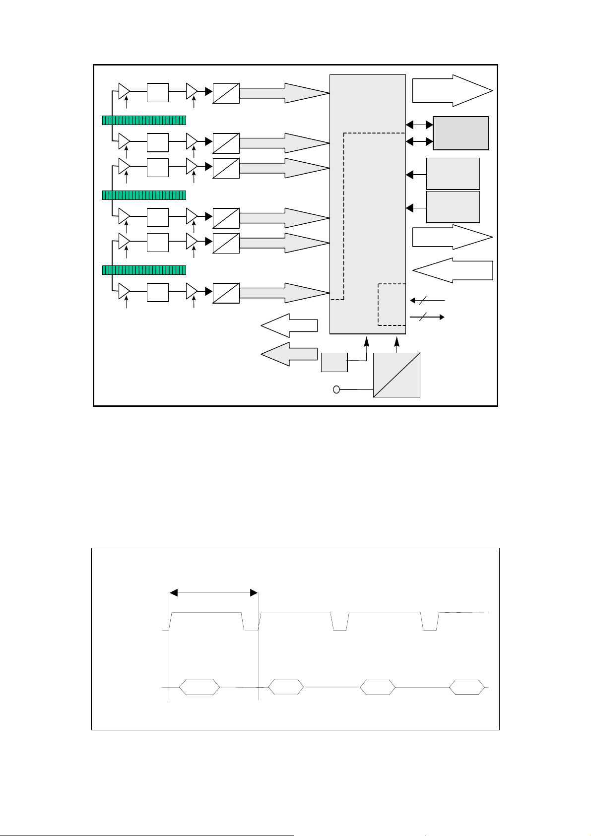
3.2 Camera Operation
The CCDs convert incoming light into electrical charge. The amount of charge generated in
each of the individual pixels is directly proportional to the intensity of light they receive. The
resulting charge packets are transferred into two high-speed CCD shift registers and transferred to the output charge-to-voltage converters of the CCDs. The generated output video is
Correlate Double Sampled (CDS) and amplified by two user accessible gain factors prior to
digitisation into 12 bits.
© TVI Vision, 18 October 2006 page 8 ( 57 )
XIIMUS R-GB-IR CL User Manual. Version 1.2
N
e
CCD
CCD
CCD
CDS
CDS
CDS
CDS
CDS
CDS
A
D
A
D
A
D
12 bits
PCU
12 bits
12 bits
Data out
on volatil
memory
vo l ta g e
monitoring
temperature
A
D
A
D
12 bits
12 bits
CTRL
m onitoring
Ctrl out
Ctrl in
A
D
12 bits
TIMING
GAIN CTRL
OSC
RS
232
DC
2
2
V
in
DC
Figure 3.3. The block diagram of the camera.
The XIIMUS cameras operate in a mono-shot mode. For each rising edge of the NewLine
signal the camera responds by sending out the digital data stream of the previous line scan
period time. The output frequency is constant. The distance in time between two NewLine
edges can be set to any value above the specified minimum. The reciprocal of this time is the
line rate (Hz).
The XIIMUS cameras have been optimised for high-speed applications. Therefore best performance is achieved at line rates of hundreds of lines per second or above.
Line scan rate
NewLine
( CC1 )
Line 1
Line 2
Line 3
Data out
Line 0
Line 1
Line 2
Line 3
Figure 3.4. The relation of the data output and NewLine signals.
© TVI Vision, 18 October 2006 page 9 ( 57 )
XIIMUS R-GB-IR CL User Manual. Version 1.2
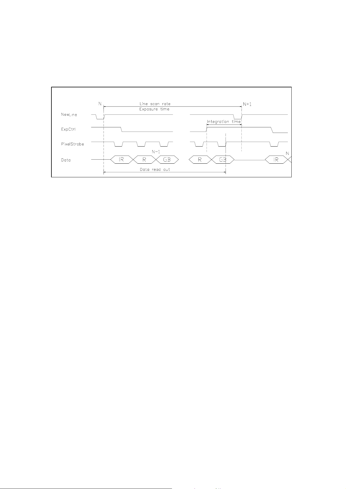
The effective integration time can be made shorter than the actual exposure time (time between two consequent NewLine (CC1) pulses, Line scan period) by holding the ExpCtrl (CC2)
signal in its active stage until the beginning of the targeted interception period. Within the
exposure time, whenever the ExpCtrl input is held low, no charge can be collected into the
pixels. This is why the actual integration time is the distance in time of the (last) rising edge of
the ExpCtrl input signal and the next rising edge of the NewLine input.
Figure 3.5. The line rate and the integration time (data is drawn for muxed output mode).
The two most common operation modes of line scan cameras are free-run mode or encoder
input driven mode.
In the free run mode both the line rate and the integration time can be precisely controlled.
But if the line rate is determined by encoder input, the integration time can best be kept
constant by using the encoder input pulse for generating the ExpCtrl signal. The NewLine
pulse is sent after a constant delay (appendix F).
The XIIMUS camera is constantly monitoring all the internal supply voltages and the internal
temperature of the camera. Temperature warnings can be monitored via the LEDs of the rear
panel or by reading the status via serial communications.
Other functions include:
• colour channel specific programmable exposure control, analogue gain, digital
gain and offset
• retrieval of the firmware versions and serial number
• non-volatile memory banks for the programmable settings
• user programmable pixel correction unit
• test pattern generation for interfacing
• self-clocking mode for operation at fixed line rate without line request input
© TVI Vision, 18 October 2006 page 10 ( 57 )

XIIMUS R-GB-IR CL User Manual. Version 1.2
4. PROCESSING OF CCD OUTPUT
4.1 Analogue video path
TVI XIIMUS cameras utilise a two channel CDD for each colour. A simplified illustration of the
analogue video path of one channel is in figure 4.1. The video path itself is completely analogue until digitised with 12-bit resolution in close vicinity of the CCD itself. All adjustments
performed on the analogue video signal are digitally controlled.
Figure 4.1. Analogue video path
The analogue video signal is first Correlate Double Sampled and amplified in the preamp
gain stage. After the CDS block it is possible to further amplify the signal with an analogue
gain stage.
The analogue video path also includes an input clamp circuit that is not drawn in the illustration. The input clamp circuit removes the CCD’s optical black offset to maximise system
headroom and the effect of gain change on the black level. The effect of this circuit causes
the digital output data to start from zero when the CCD is exposed to dark. If desired, the
dark level register can be used to set a positive offset in the output data. If this parameter
differs from zero, the dark level of channel in question will have an offset equal to the dark
level setting. Changing this setting can be desirable when using the pixel correction unit,
since the pixel to pixel variations in dark will be present in the raw data enabling better correction.
Lastly the 12-bit data streams from the two output channels are digitally multiplexed into one
data stream to represent the CCD output.
© TVI Vision, 18 October 2006 page 11 ( 57 )

XIIMUS R-GB-IR CL User Manual. Version 1.2
4.2 Pixel correction unit
4.2.1 Description
The TVI XIIMUS series line scan cameras incorporate a user programmable real time pixel
correction unit, PCU. The PCU can be set up by downloading appropriate correction data via
the serial port to the camera.
The PCU can simultaneously perform white balancing, removal of pixel to pixel offsets
(PRNU & DSNU), lighting profile correction, removal of lens curvature and/or perform custom
operations on the output data of the camera.
4.2.2 Data order
The correction data consist of 24 bits of data per colour pixel. Thus, for a full R-GB-IR pixel
the user has to provide 72 bits of data. The data is sent to the camera via serial
communications port starting with the first pixel in the line. Colours are sent in IR-R-GB order
to the camera. The start of the transmission to the camera is illustrated below, each capital
letter corresponds to one byte (8 bits) of data:
1 2 3
IrIrIr RRR GbGbGb IrIrIr RRR GbGbGb Ir..
Within a single colour pixel the data is ordered into a multiplier and an offset. The multiplier
consists of 14 bits and the offset of 10 bits. Thus, the three bytes that make up the correction
data for one colour pixel are internally divided on a bitwise level as follows:
Ir (byte 0) Ir (byte 1) Ir (byte 2)
Multiplier Offset
13 12 11 10
9 8 7 6 5 4 3 2 1 0 9 8 7 6 5 4 3 2 1 0
Please refer to the serial communication section of this document for additional information
on how to download correction data to the camera.
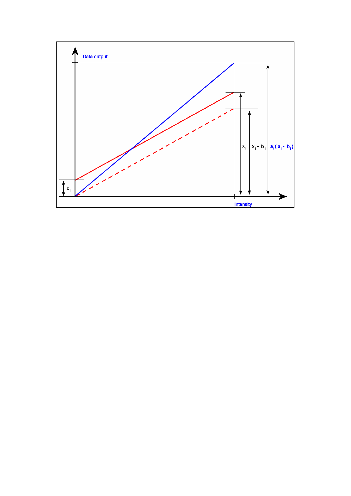
4.2.3 Correction algorithm
The pixel correction unit (PCU) utilises a simple linear algorithm to correct the digital output
data of the camera. The formula below is used to correct all data once correction is enabled:
yi = (xi - bi) x a
y
= corrected output data
i
x
= camera raw data
i
b
= offset to be subtracted from the raw data
i
a
= multiplier for scaling of data
i
Since the offset b
camera dark level, which is typically around 40 DU. As an example, the user might want to
subtract the background of the image instead of the dark level.
i
has a 10-bit range, it is possible to subtract greater values than the
i
© TVI Vision, 18 October 2006 page 12 ( 57 )
XIIMUS R-GB-IR CL User Manual. Version 1.2
Figure 4.2. Correction algorithm.
The multiplier a
has a 14-bit range. The multiplier is scaled so that a 14-bit multiplier value of
i
4096 DU by default equals multiplying by one. So, in order to increase the signal of a pixel it
has to be multiplied with a number greater than 4096 DU and accordingly it has to multiplied
with a smaller number to attenuate the signal. This means that a single pixel cannot be multiplied with a multiplier greater than 4 or attenuated more than into 1/4096. Please note that
multiplying with a number that is larger than one (4096) will result in some more noise in the
image, because the original data is scaled up (“stretched”) to cover a larger range.
By altering the content of the shifter register, it is possible to reset the multiplier unity level to
any power of two between 128 and 16384. Please notice, that setting this register to 16384
will not permit any amplification, but on the other hand will permit fine resolution attenuation.
Also, setting this register to low values will permit much amplification, but will make the multiplier effect coarser at values close to the selected unity value.
As mentioned above, the correction unit can perform multiple corrections on the image with
one set of correction data. White balancing or any user defined colour balance can be
achieved by multiplying the colour channels that have a response differing from the desired
response with suitable multipliers.
© TVI Vision, 18 October 2006 page 13 ( 57 )

XIIMUS R-GB-IR CL User Manual. Version 1.2
4.2.4 Implementation of the correction
Figure 4.3. Block diagram of the correction data path.
The correction algorithm is implemented as illustrated above for each colour channel. Firstly,
all offsets are subtracted from the raw 12-bit CCD output data. This includes the pixel to pixel
offsets in the dark (DSNU) and any custom subtractions. In the diagram this subtraction is
marked as SUB
. Also, the colour channel specific offset is subtracted from the raw data.
i
Thus, altogether it is possible to subtract half of the camera dynamic range from the raw
data.
Secondly, after performing the subtractions, the data is multiplied with a 14-bit pixel specific
multiplier. This will result in a maximum of 26 bits of data per pixel, out of which, the topmost
12-bits are routed to the data output of the camera. The output data passes through a left
shifter where it is possible to digitally amplify the data by shifting it zero to seven positions to
the left. Also, the shifter will shift the data to the correct location depending on the unity multiplier level set in the shifter register.
Example:
The shifter register is set to 7, which equals 128 as a unity multiplier. The digital gains are set
to 7 as well, which equals 128x digital gain. In this case, the result after the multiplication is
shifted up 14 positions which means the lowest 12-bits of the resulting 26-bits are shifted to
the data output.
Example on performing multiple corrections
White balancing can be achieved by selecting the multipliers so that the data values on all
colour channels are equal in digital response from pixel to pixel. Normally, the channel that is
closest to saturation is selected as a reference where the other channels are corrected.
Other choices are possible but they limit the dynamic range of the output signal. The image
below depicts a typical situation. In the image, the output of the infrared channel is where the
other two channels are corrected. Now, to achieve white balance, the infrared channel line
has to be multiplied with a constant one for every pixel in the line and the red and bluegreen
channel pixels with multipliers of little over one varying from pixel to pixel, so that each colour
pixel will have a balance of its own.
© TVI Vision, 18 October 2006 page 14 ( 57 )
XIIMUS R-GB-IR CL User Manual. Version 1.2
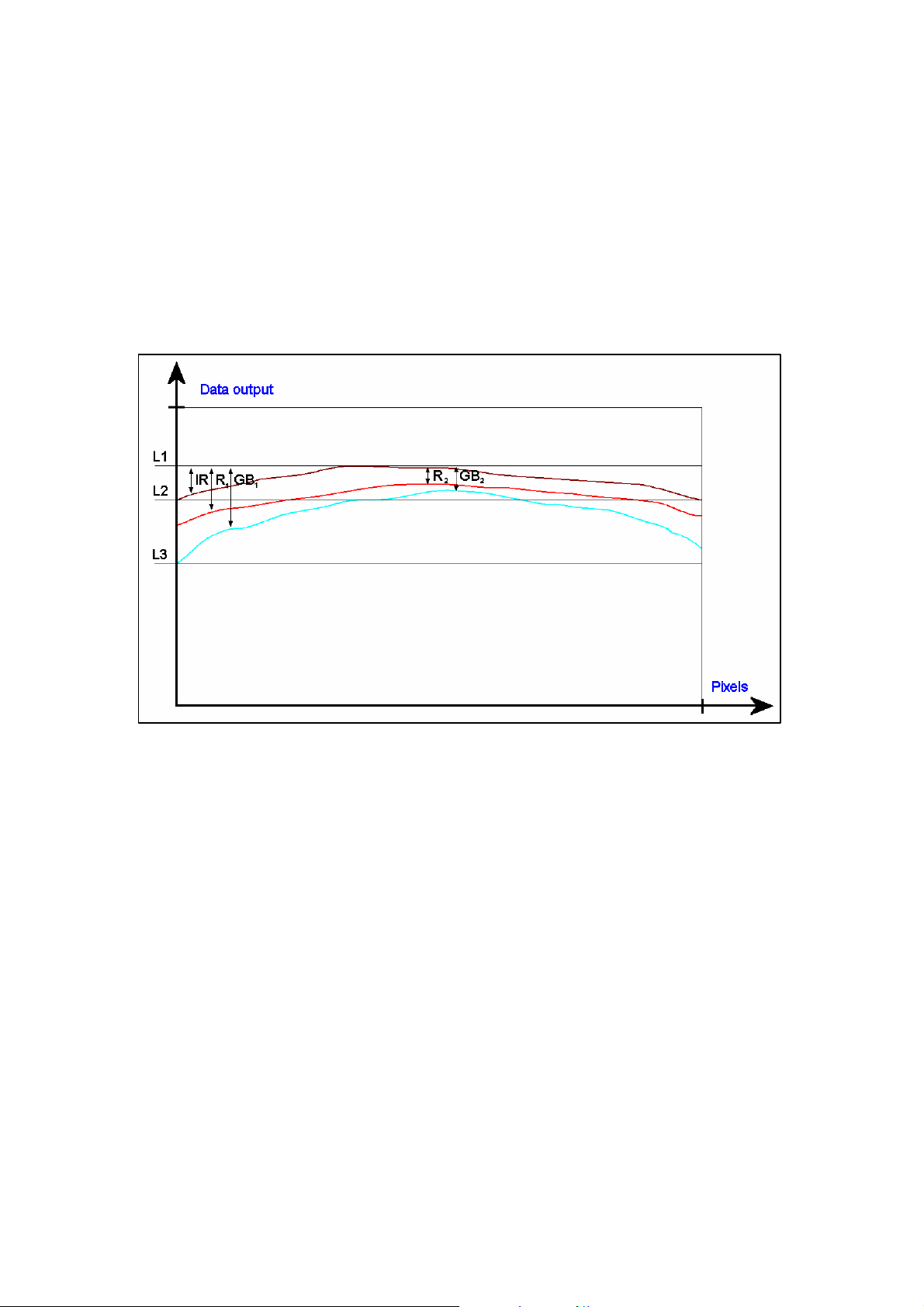
In order to remove unevenness of the lighting profile and lens curvature along the vector at
the same time as when performing white balancing, each individual pixel along the vector
needs to be scaled to the corresponding infrared maximum value (L1). Now, in this case, in
order for the line profile on all colour channels to equal line L1, the infrared channel line also
has to be scaled. Thus, at the beginning of the infrared line, the lowest pixel value at level L2
has to be multiplied with a multiplier IR
, so that it equals line L1. Accordingly, at the start of
x
the bluegreen channel line, the line L3 has to match line L1 for the camera to be in white
balance.
As illustrated in fig. 4.4, the bluegreen channel will have the largest multipliers and the centre
of the infrared channel line will have multipliers close to unity. Also, the far ends of each
colour channel will have the largest multipliers of the colour channel in question.
Figure 4.4. Correction in the direction of the vector.
© TVI Vision, 18 October 2006 page 15 ( 57 )
XIIMUS R-GB-IR CL User Manual. Version 1.2
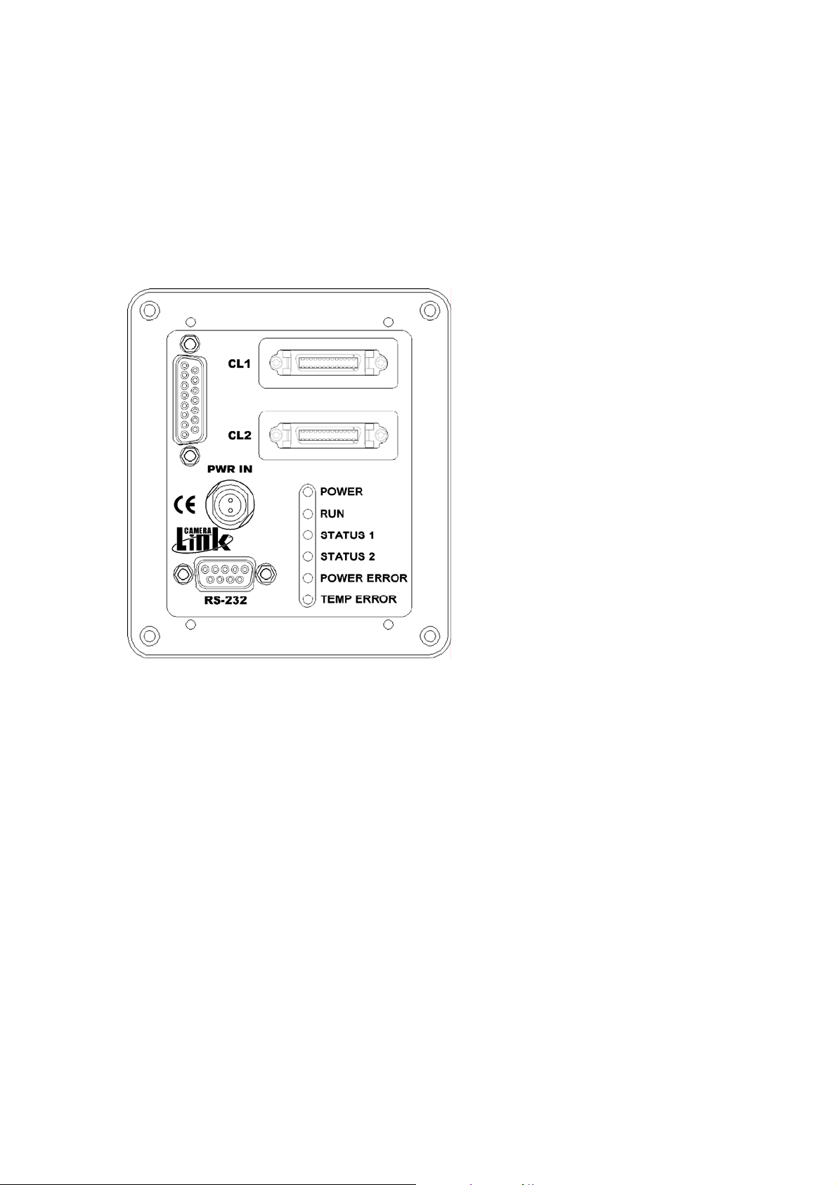
5. CAMERA INTERFACE
All the electrical connections of the XIIMUS colour line scan camera are made via the rear
panel.
The DC power is input via the 2-wire, shielded power cable (included in the delivery).
The two Camera Link
grabber boards or users' own electronics.
Figure 5.1. The rear panel layout for Camera Link
®
connectors are used for interfacing to commercial Camera Link frame
All signals are available on the two
Camera Link connectors. The interface
is designed according to Camera Link
specification v1.1.
Standard RS-232 interface is used for
modifying the parameters of the
camera. The serial port interface is
also available on the first Camera Link
connector according to the specifications. The port is set according to the
purchase order. The selection can be
swapped by software. Additionally,
there is a hardware method to move
the port to RS-232 connector (instructtions available on request).
Six indicator LEDs (on the right hand
side) show the status of the camera.
®
models.
5.1 Power input
The connector is labelled as ‘PWR IN’. A power cable is included in all the camera shipments. The bottom most pin of the cable represents the positive supply voltage and the topmost is the respective zero volts. The mating power connector part number is: odu S21L0CT02LPH0-6200. The recommended cable bend relief can be ordered with p/n code: odu
701.022.208.960.050.
The XIIMUS cameras operate from a single supply voltage of nominally +24 V
500 to 1000 mA depending on the operation mode and the external terminations of the output
signals.
The maximum power consumption is 26 W. For low frequency line ripples (less than 120 Hz)
± 10 % of ripple is acceptable as long as the voltage level stays between +20 to +36 V
© TVI Vision, 18 October 2006 page 16 ( 57 )
at typically
DC
DC
.

XIIMUS R-GB-IR CL User Manual. Version 1.2
Supply voltage:
Nominal: +24 V
Range: +20 to +36 V
DC
DC
Supply current:
Typically: 500 to 1000 mA
Maximum: 1.1 A (at +24 V
and at power-up only)
DC
Ripple:
± 10 % (max 120 Hz)
- voltage level (=nominal + ripple) must stay
between +20 to +36 V
5.2 LED indicators
From top downwards the LEDs are as follows:
POWER, green
ON: power input OK
RUN, green
ON: normal operation
OFF: ¹ The higher temperature limit has been exceeded and the
camera operation has been shut down. After the external temperature has fallen into the specified range, switch the power
once OFF and then ON again.
² The camera did not start up properly. Check the input power
lines and the POWER LED. The power supply must be able to
supply enough current quickly at beginning of the power-up.
STATUS 1, green
ON: correction unit (PCU) is enabled
OFF: correction unit (PCU) is disabled
STATUS 2, green
ON: camera is ready for operation
OFF: camera is performing internal boot cycle
PWR ERROR, red
ON: at least one of the internal supply voltages has failed
© TVI Vision, 18 October 2006 page 17 ( 57 )

XIIMUS R-GB-IR CL User Manual. Version 1.2
TEMP ERR, red
ON: Warning of too high an internal temperature. If the camera cools
down, this warning will be removed, but if the temperature rises
further the camera will be stopped permanently until the next
power-up. Please note that this is only an early warning of high
operating temperature and that it is permitted to use the camera
even when this warning is continuously on. The status of
temperature monitoring can be read via serial communications.
5.3 Data Connector
Two MDR-26 connectors handle the data communication according to the Camera Link
specification. The connectors are labelled CL1 and CL2. CL1 is for Base Configuration. Both
connectors are needed for Medium and so called Dual Base Configurations (non-standard).
Cables can be secured with either screw locks or latches.
All signals are specified by the Camera Link standard, except the four Camera Control inputs:
CC1 NewLine
- the rising edge defines the change-of-line moment (after a constant delay)
- period is the line rate
CC2 Exposure Control IR (or all channels)
- exposure control signal for the IR channel
- the effect for this is defined by the mode that is selected via
RS-232 interface or Camera Link serial port
- as default this signal is common to all the three CCDs
- a low level resets all the pixels
- should be constantly high, if full time exposure is needed
- a constant '0' results in dark images
CC3 Exposure Control R
- exposure control signal for the Red channel when camera is set to
individual exposure control mode
CC4 Exposure Control GB
- exposure control signal for the greenblue channel when camera is set to
individual exposure control mode
For cabling please refer to the Camera Link specifications. TVI Vision also provides Camera
Link cables. Please contact sales (sales@tvivision.com).
All the input signals are internally terminated by 100 Ω resistors.
All the output signals should be terminated respectively (one 100 Ω resistor connected
between the positive and negative wire of each signal pair).
Appendix A shows the output bit port assignments of all the available Camera Link modes.
Appendix B presents the timing details of the interface signals.
© TVI Vision, 18 October 2006 page 18 ( 57 )
 Loading...