

Page 1
XIEGU
100 W Solid-State Linear Power Amplifier
XPA125
Instruction Manual
Copyright © 2010~2017 Xiegu Communications
Page 2

XIEGU COMMUNICATIONS
2
Important reminder:
Before operating the equipment please
study this instruction manual carefully, and
retain it for future reference.
Safety considerations:
Features:
-
RF power amplifier with inbuilt antenna
tuner (ATU).
-
Maximum RF output power of
125 Watts.
-
Auto tuning function.
-
Wide frequency range of 0.5 – 50 MHz.
-
Harmonic suppression of 39 dB
-
Maximum output power can be
automatically regulated via the ALC
control when used with an X108G or
X5105 transceiver
Do not use equipment during an electrical
storm.
Do not expose the unit to moisture.
Use this device responsibly and observe all
local laws and regulations.
Caution! High RF voltage at antenna
connector!
Packing list:
① XPA125.. .. .. .. .. .. .. .. .... .. .. ..1
①
② Power supply cable ................ 1
③ Date cable .............................. 1
④ Communication cable ............. 1
⑤ Service card ............................. 1
②
③
⑤
④
Page 3

XIEGU COMMUNICATIONS
3
1 XPA125 Specifications
1.1 Amplifier:
Frequency range: 0.5 – 54 MHz
Maximum output power:
1.8 - 30MHz
≥110W
50 - 54MHz
≥90W
Maximum operating ambient temperature: 55℃
Gain: 13dB ( 2dB)
Supply voltage: 12 - 14.5 V DC
Current draw @ maximum output:
Standby: 260 mA
Transmit: 30A
1.2 ATU:
Tuning frequency range: 1.8 – 30 MHz/50 – 54 MHz
Maximum tuning range: 14 - 500Ω
1.3 Product specifications:
Dimensions: 260 x 150 x 100 mm (not including control knobs, feet, handles, etc.)
Weight:2.66
Kg(host only)
±
@Max
@Max
Page 4
XIEGU COMMUNICATIONS
4
2 Equipment description
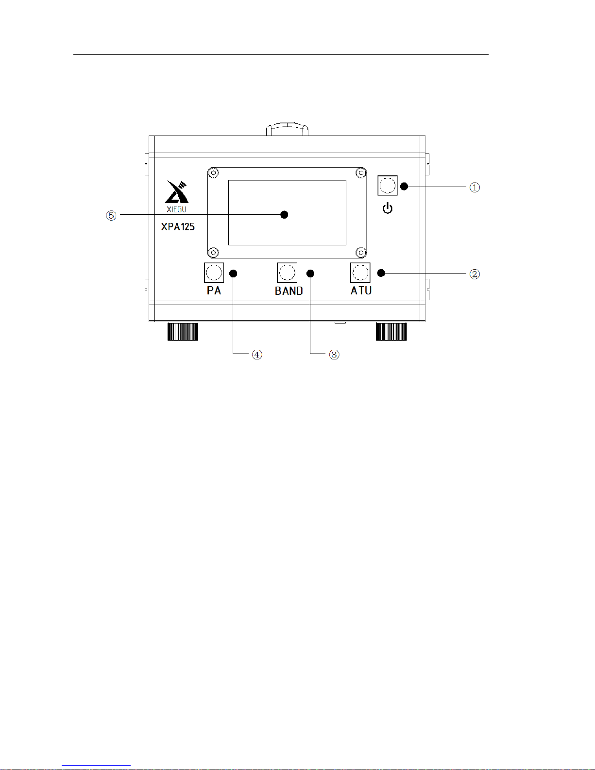
2.1 Front panel layout:
① Power key
When XPA125 is turned on, press this button and hold for 2 seconds,
XPA125 will shut down.
When XPA125 is turned off, press this button and hold for 2 seconds,
XPA125 will turn on.
② ATU function key
Via this button you can access the automatic antenna tuning function.
③ BAND selection key
Using this button you can select between manual band switching or
automatic band switching.
In manual band switching mode, the XPA125 will change bands in the
following order:
160m→80m→60m→40m→30m→20m→17m→15m→12m→10m→6m
④ PA key
Used to switch the power amplifier into or out of circuit.
Page 5
XIEGU COMMUNICATIONS
5
⑤ LCD
All working status information is displayed here. The display is covered by an
organic glass protective plate.
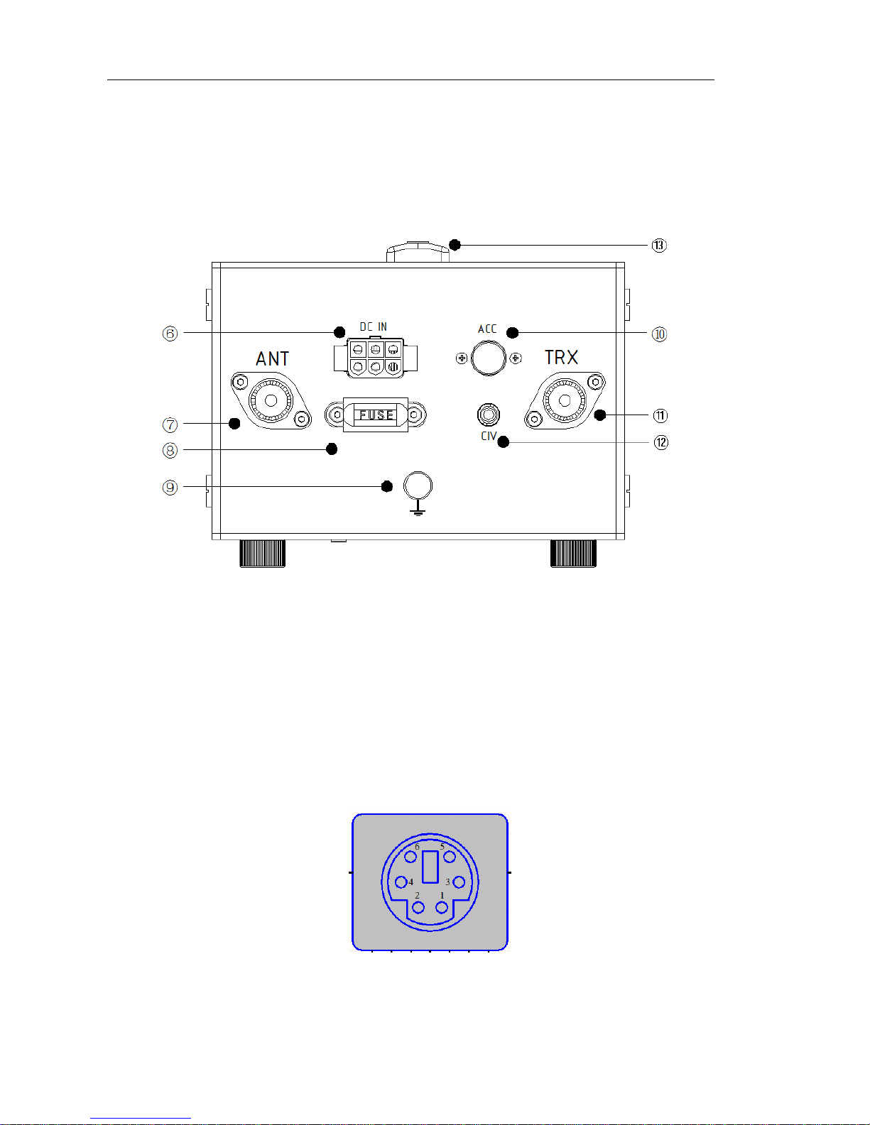
2.2 Rear panel layout:
○
6 DC IN Power supply socket:
The XPA125 requires a 12 - 14.5 V DC supply
○
7 ANT Connector:
The ANT socket is connected to the antenna, the connector model is SL16-K.
○
8 FUSE Holder:
Internal fuse holder. Fuse rating is DC 30A.
○
9 Ground
○
10 ACC socket:
The data interface connections are as follows:
Page 6

XIEGU COMMUNICATIONS
6
PIN1:NC
PIN4:
ALC input
PIN2:PTT Signal input
PIN5:
NC
PIN3:Band voltage input
PIN6:
GND
○
11 TRX Socket:
The TRX interface is connected to the transceiver output, the connector
model is SL16-K.
○
12 CIV interface:
This interface is for XPA125 firmware updates and connection to a PC.
○
13 Handle
2.3 Display interface layout:
⑴ Input SWR value:
Displays the SWR value of the XPA125 input.
⑵ Operating voltage:
Displays the value of DC voltage supply to the XPA125.
⑶ Operating current value:
Displays the current being drawn by the XPA125.
⑷ Output stage temperature:
Displays the current temperature of the PA stage.
⑸ Output SWR value:
Displays the SWR value of the XPA125 output.
Page 7

XIEGU COMMUNICATIONS
7
⑹ Power amplifier status:
Displays the overall status of the power amplifier as a whole.
Indicates that bypass mode is selected, the power amplifier is switched out of
circuit.
Indicates that the power amplifier is operational.
RX Indicates that the unit is in receive mode.
TX Indicates that the unit is in the transmit mode.
⑺ Input power value:
Displays the power input value to the XPA125 in Watts.
⑻ Current working band status:
Displays the current working band, and whether automatic or manual mode
is selected.
(9) Output power value:
Displays the output power being delivered by the XPA125 in Watts.
Automatic antenna tuner unit (ATU) status:
Displays the status of the automatic antenna tuner.
Indicates that the XPA125 is not connected to the automatic antenna tuner
unit.
Indicates that the XPA125 is connected to the automatic antenna tuner unit.
When tuning is successful,【INUSE】will be displayed.
If tuning fails,【Fail】will be displayed.
(10)
Page 8

XIEGU COMMUNICATIONS
8
3. Operating instructions
3.1 Wiring connection method
3.1.1 Method for connecting XPA125 with X108G
The XPA125 can be directly connected to an X108G, which can then control
the band switching and ALC functions of the amplifier.
-
The ACC data cable supplied with the XPA125 is connected between
the ACC ports of the two units. Both connectors are the same so
either end of the cable can be connected to either socket.
-
Use suitable RF coaxial cable to connect the X108G ANT port to the
XPA125
TRX port.
-
XPA125 ANT port should be connected to the antenna.
3.1.2 Method for connecting XPA125 with X5105
Use the dedicated connection cable CN-115 to connect the X5105 ACC port with
the XPA125 ACC port. Please note the need to distinguish between the different
plugs of the connection cable CN-115.
3.1.3 Method for connecting XPA125 with X1M
As the X1M does not have a dedicated ACC interface and PTT signal output, it
can’t be directly connected to the XPA125. A CN-17 converter is required to
connect an X1M to the XPA125.
Page 9

XIEGU COMMUNICATIONS
9
3.1.4 Connection method between XPA125 and other QRP radio
If you want to start the XPA125 power amplifier and put it into the transmit
mode, you need to set the PTT port to a low level [level≤0.1V].
If the PTT output signal of the transceiver is at high level, the high level
needs to be converted into a low level, and then input to the XPA125
[ACC-PTT] port.
Pin 2 of the XPA125 ACC port is the PTT input port
In order to achieve automatic band switching, the corresponding band voltage
is needed. XPA125 band control voltage information is as follows.
BAND
LEVEL(mV)
BAND
LEVEL(mV)
BAND
LEVEL(mV)
1.8 MHz
230
14.0 MHz
1380
50.0 MHz
2530
3.8 MHz
460
18.0 MHz
1610
----
----
5.0 MHz
690
21.0 MHz
1840
----
----
7.0 MHz
920
24.0 MHz
2070
----
----
10.0 MHz
1150
28.0 MHz
2300
----
----
3.2 Procedure:
3.2.1 Using the power amplifier unit [PA unit] (ATU unit is set to BYPS)
-
Press the PA key, so that the state of the amplifier is
[INUSE].
-
If your connected transceiver is an X108G or X5105, please set
the output power to 5 W.
-
If you are using any other QRP transceiver, please set the output
power to 1 W.
-
Set your transceiver to CW mode, press the
CW key
to
transmit,
and the XPA125 amplifier will be activated
.
-
The output power of the XPA125 can be adjusted by adjusting
the output power of
the connected transceiver.
Page 10

XIEGU COMMUNICATIONS
10
Warning:
1. Do not allow the maximum output power of the amplifier to exceed 120 W.
2. Using the XPA125 at high power levels for extended periods can lead to
overheating and potential damage to the PA stage.
3.2.2 Band switching
-
You can switch between the two modes of
[AUTO- MANUAL]
via this key.
-
If you want to connect the XPA125 to an X108G or X5105,
please set XPA125 to
[AUTO]
mode.
-
If you want to connect the XPA125 to other devices,
please set XPA125 to
[MANUAL]
mode and manually
switch to
the desired frequency band.
Manual switching of frequency bands follows this order:
160m→80m→60m→40m→30m→20m→17m→15m→12m→10m→6m
3.2.3 Using the automatic antenna tuner unit [ATU] (PA unit is set to BYPS
state).
-
Press the
[ATU]
button so that the current state of the amplifier
is [INUSE].
-
Set the transceiver mode to CW & set the output power to 5 W.
-
Press the CW key to transmit, and the
XPA125 PA
amplifier
stage will be activated. The XPA125 ATU unit will start, the
screen will display [TUNE].
-
If tuning is successful, the screen will display
[INUSE].
-
If tuning fails, the screen will display
[Fail].
If you need to re-tune, you can press the [ATU] button for two seconds to
force the XPA125 ATU unit to start re-tuning.
After successful tuning, switch the transceiver to the desired state for use.
Page 11

XIEGU COMMUNICATIONS
11
3.2.4 Combined use of power amplifier + automatic antenna tuner
-
Press the [PA] button so the current state of the PA unit displays
[INUSE].
-
Press the [ATU] button so the current state of the ATU
unit displays
[INUSE].
-
Set the transceiver mode to CW, the output power to 5 W, and
press the CW key.
-
If the current SWR value is more than 3.0, the ATU unit will start
tuning automatically. At this time
the PA unit will be disabled.
-
If the current SWR value is less than 3.0, the ATU unit will start
tuning automatically, and the PA unit will be activated.
-
If the current SWR value is more than 3.0, and automatic tuning
fails
, the XPA125 will automatically switch to bypass mode
and display this information on the screen.
3.2.5 Flexible configuration of PA unit and ATU unit
The ATU unit and PA unit of XPA125 can be used independently of each other.
You can therefore use the XPA125 as either an automatic antenna tuner or a
separate power amplifier. You can also bypass both units, and your transceiver
will then be connected directly to the antenna.
3.2.6 Protection and warning
The XPA125 incorporates a variety of intelligent protection functions to ensure
as far as possible the safety of the equipment in daily use. When the XPA125
enters an abnormal state, it will immediately enter protection mode and switch
to bypass mode.
3.2.7 Remove protection and warning
Release the PTT button. Protection will be disabled and the XPA125 will return
to the receiving state.
Warning messages are as follows:
SWRI too high! (Input value of
SWR is high)
Idd too high! (Operating
current is too high)
PIN too high! (High input
power)
Vdd too high! (Input voltage is
too high)
SWRO too high! (Output value of
SWR is high)
Wrong band! (Filter error)
PO too high! (High output
power)
Gain too low!
Temp too high! (Operating
temperature is too high)
Efficiency too low!
Page 12

XIEGU COMMUNICATIONS
12
When high SWR, high current, high voltage, over temperature and other
error states are detected, the XPA125’s internal sensors will trigger the
protection function beyond a certain threshold. The threshold of each
sensor is as follows:
-
High SWR:≥3.0
-
High current:≥30A
-
High voltage:≥15V DC
-
Over temperature:≥100℃
Warning
When the XPA125 current dra w is too high (more than 30A), o r a
short circuit occurs, the fuse on the rear panel may blow. The unit will
then no longer turn on. Please check the status of the fuse if this occurs.
Page 13

XIEGU COMMUNICATIONS
13
Fault
description
Possible reasons
Solution
Unable to turn on
your XPA125
Power cord is not connected Connect power cable correctly
The fuse on the back of the machine
has blown
Replace fuse(30A)
Power cable connection is bad Replace or repair power cord
Power supply connection reversed Return to distributor
Other circumstances Return to distributor
No reception
Antenna is not connected Properly connect the antenna
Antenna failure Replace or repair antenna coax
No communication
Please confirm the propagation
characteristics of the current band
Other circumstances Return to distributor
No trasmission
Antenna is not connected Connect antenna
Inadequate power supply current Replace the power supply
SWR is too high, protection has
been triggered
Start ATU/replace antenna/coax
Incorrect working mode
Select the correct working
mode
Power amplifier unit not enabled Set the PA unit to INUSE
Other circumstances Return to distributor
Antenna tuning
function does not
work
Antenna tuning function is not
enabled
Set the ATU unit to INUSE
Screen has no
display
Power cord is not connected Connect power cable correctly
The fuse on the back of the machine
has been blown off
Replace fuse(30A)
Other circumstances Return to distributor
Smoke comes
from equipment
Replace smoke – Only joking,
return to distributor
4. General troubleshooting
The following are general troubleshooting suggestions. If they do not resolve
the problem the unit will need to be returned to your distributor. Please do
not disassemble the unit as this will invalidate the warranty.
Page 14

XIEGU COMMUNICATIONS
14
After-sales service policy
1. Warranty:
This product has a one-year warranty effective from the date of purchase.
This warranty covers only manufacturing- and parts defects. It does not
cover damage caused by lightning, excess voltage on the power supply,
accidental damage or purposeful damage or misuse.
If the product needs warranty repair within two weeks of receiving the
product, XieGu will pay for the shipping both ways. After two weeks XieGu
will pay only for return shipping.
If the product is not covered under warranty, the customer pays for shipping
both ways plus the cost of the repair.
2. Warranty limitations:
Any of the following will void the warranty applicable to the product and its
accessories:
A. Modification-, removal-, or maintenance of the internal circuitry,
without permission and authorization;
B. Unauthorized change of product’s embedded software;
C. Immersion in liquid or signs of external damage;
D. Warranty period expired;
E. Product’s serial number is missing, torn or blurred so we cannot determine if
Page 15

XIEGU COMMUNICATIONS
15
the radio is under warranty;
F. Product was not bought from XieGu or authorized distributor of XieGu.
*None of the following conditions, are covered by the warranty:
A. Damage caused by improper use by the user;
B. Damage caused by an accident;
C. Damage due to incorrect testing, maintenance, debugging, or other changes;
D. Damage is not caused by the material or the quality of production;
E. Damage to the shell or other external components due to improper use.
Contact us: service@cqxiegu.com
制造商:深圳协谷通信技术有限公司
地址:东莞市塘厦镇蛟乙塘宝石路12号B栋4楼
电话:+86 0769-86346464
Page 16

XIEGU COMMUNICATIONS
16
XIEGU COMMUNICATIONS
www.cqxiegu.com
 Loading...