

Page 1
1
CGMeter Basic
Users Guide.
Pl. Pere Llauger, nau 18. 08360, Canet de Mar, Barcelona,Catalonia,Spain
E-mail: sales@xicoy.com. Fax: +34 933 969 743 web: www.xicoy.com
Xicoy WEEE register number: ES004749 & DE 36558999
© Copyright 2017, Xicoy Electronica SL. All Rights Reserved
Manual contents & design: Gaspar Espiell. V0.9
Page 2

2
Welcome!
Congratulations on the purchase of your weight, balance & angle meter. Xicoy are
dedicated to the design and production of electronic controllers to the highest
standards of quality and reliability to bring you the customer the very latest next
generation designs.
Features:
The Xicoy CGMeter Basic allows both weight and balance of aero models of more than
50kg (110lb) weight, being limited by the maximum weight on a single scale of 25kg.
Each scale is made from tempered & anodized aluminum and has a resolution of 1g.
The scales can be calibrated by the end user if necessary.
The system has a standard Wi-Fi server to where the user can connect any terminal
(phone, tablet and computer) capable to connect to a Wi-Fi network and has a
standard web browser to navigate through the CGmeter Web pages. Software is selfcontained and it is not necessary to install any application to the terminal. The system
has been tested with Android, IOS, Windows, Mac and Linux. Current software is
available in English, French, German, Italian and Spanish.
Optionally the user can purchase an angle meter/laser pointer to measure the
deflection angles of any surface with an accuracy of 0.1º.
This module is FCC and CEE certified.
Measuring CG and Weight:
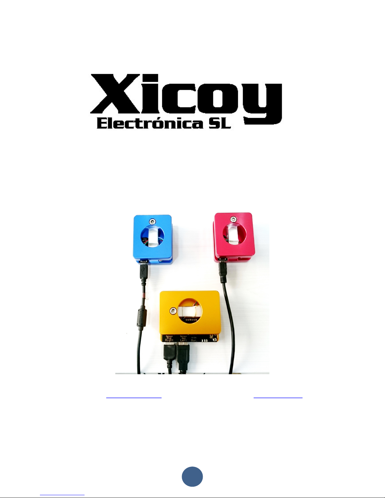
The system consists of 3 x digital weight sensors, to be placed under the wheels of the
airplane. For easy identification, the RED unit should be placed under the LEFT wheel,
BLUE unit under the RIGHT wheel and YELLOW unit under the nose/tail wheel. The
Yellow is the main unit and has the Wi-Fi server plus control electronics.
Page 3

3
Electric connections:
Connect the Blue and Red sensors to the yellow main unit using the leads supplied
each sensor in its own socket. Connect a battery between 5 and 10 volt on the battery
socket as per picture.
Connecting your terminal to the CGMeter:
Inside the main unit there is a standard Wi-Fi server, like
your home router. First step is to connect your terminal
(phone/tablet/computer) to the Wi-Fi network exposed by
the CGMeter.
Select the
XicoyCGMeter
network and connect to it.
Ignore the message that warns that
this server is not connected to
Internet; we want to balance a plane,
not to surf the web!
Once your terminal is connected to the
XicoyCGMeter
network,
then open the web browser and type “cg/”. Don’t forget the “/”,
it is important.
The browser will display the initial
page where you can select the
language. Touch the button of your
preferred language, the setup finished!
The main page is divided in four sections. On first one there
are all the measures done by the system. Next allow to
entry the data from your plane, third allow managing the
internet connection and last one allows the calibration of the
sensors.
Page 4

4
Basic operation:
This instrument allows to do several measures, and to do so, it needs to know some
data from your plane. Depending on your needs, some of the data is not necessary to
be entered. We will describe step by step the measures that can be done, the data to
be entered to do these measures and how to take these measures.
Measuring the weight:
To measure the weight, it is not
necessary to enter any data, but it is
important to check and calibrate the
sensors, especially if they have got
mechanical stress, like transport or
shock, if the temperature is significantly
different since last calibration, or at
least once per year. See the section of
“
sensor calibration
” for details.
First place the scales and the plane over a flat and hard surface. Don’t put the plane
over the scales yet. First connect the battery, connect the terminal to the Wi-Fi server
as described above, and the touch the “Tare” button, to
set all 3 scales to zero. If the ambient temperature is
significantly different (i.e., the instrument has been
inside a car in the sun and is hotter than ambient
temperature), then wait few minutes so that the sensors
equalize its temperature to avoid a measure drift later.
Once the tare is complete and all 3 scales are at zero,
place the plane over the scales. Check that the wheels
are centered over the sensors and don’t make any force
sideways that could distort the measure of the real
weigh, if landing gear has some play, it is easy to push
one leg against the other, causing the scales to sit at
angle and generating instability and errors.
Now you can read on the terminal the weight on each
sensor and the total weight. All data is displayed in
Metric and imperial units at same time.
Measuring the current CG position:
OK, now we know the weight of our plane and we know that it weights a little more on
left side that on right side. Now we can measure where the CG actually is.
First of all, and this is really IMPORTANT, the plane should be always placed in level
flight. Not useful to balance the plane with its nose pointing up or down, when during
in flight, the plane will not fly in the position you have balanced it.
Page 5

5
If the plane you are balancing sits on the ground in nose up/ down attitude, then add
some height under the sensors until the plane “looks” like it was flying. For extra
accuracy you can measure the wing or tail incidence, but usually not necessary.
To calculate where the CG currently is, the instrument needs to know the weight on
each scale, plus the distance between the centers of the scales.
There are different methods to take this measure accurately, like drawing lines on the
table and centering the sensors over them. Our preferred method is described here, it
doesn’t require drawing lines on the table, but one should remember always that the
measure we need is the distance between the CENTERS of the sensor under the
nose/tail to the center of a line passing through the centers of the sensors under the
mains.
We can use the edge of a
table, or a line in the
floor as reference point.
Then we can use a measuring tape placed as per the pictures.
Remember that we need to know the distance between
the centers of the sensors, and with this procedure we
are measuring the distance between the edges of the
sensors.
We should take in to account the offset between the
center of the scale and the edge of the scale.
The sensors, if placed as per the above pictures have an offset of 25mm.
Reading on the tape, in the above example we see that the edge of the sensor under
the nose wheel is at 720mm. So its center is at 720 + 25 =745mm from the edge of
the table.
The edges of the sensors under the main wheels are flush to the edge of the table, so
the center is at 25mm from the edge of the table.
Then 745 – 25 = 720mm, this is the distance between the centers of the sensors that
we must enter in the app to calculate the current position of the CG.
Page 6

6
Now touch the “Data Entry” tab in the app. This will show a
form to enter the data.
First optionally you can enter the name of the model. Not
necessary, but could help in to remember to what model
belong the settings currently in use.
Next you should choose the configuration of the landing
gear.
And finally, you can enter the value we have just
measured. You can enter in mm or in inches; the app does
the conversion automatically.
Click on the “Submit” button on the bottom of this page,
the settings will be stored and the measures page
automatically displayed.
Scrolling down on this page, you will find the balance
section. With the data provided so far, the instrument is
only capable of to calculate where the current CG of the
plane is.
In our example, we can see that our Viper has currently its
CG located at 58mm in front of the center of the main
sensors, or at 58+25=73mm from the edge of the table.
Now we want to know a little more, we want to know if the plane is well balanced,
nose heavy or tail heavy. To have the CGMeter helping in this measure, we need to
feed it with more data. It needs to know where the CG should be located as per the
drawings of the plane designer/manufacturer.
Follow the indications of the drawing of the plane to locate the spot where the CG
should be placed, and mark it on the plane belly for ease localization.
Once we have the CG position marked in the plane, it’s
time to measure the distance from the CENTER of the
main sensor to the desired CG location.
This measure should be done with the plane in the
same position as when later we will check the balance.
Levelled in flight position and if the gear compress
under the weight of the plane, we must assure that
always we will have the same degree of compression,
to avoid changes in these distances.
We propose two methods to do accurately this measure, depending if you own our
laser/angle meter module.
Page 7

7
Measure using the laser:
Place the laser module close to the measuring tape, and move it until the line is
centered to the mark of the CG. Annotate the measure (72mm on the picture.
Measure using gravity:
Don’t worry if you don’t own the laser module, using the gravity the measure is easy to
do too. You just need three “high technology” components. Adhesive tape, sewing
thread and something heavy and pointed like an eyebolt.
Stick the sewing thread on the center of the CG mark using adhesive tape, and
annotate the measure (72mm on the picture).
Accuracy is similar in both cases, and more than enough for our application, but when
using the laser module, checks that it seats flat over the table, as if it is not absolutely
levelled, it can cause wrong readings. And when using the gravity, check that the
table is levelled. In both cases check that the sensor and the measuring tape are
correctly aligned to the reference used, that is the edge of the table in this example.
Now we know that the manufacturer recommends that the CG of our plane be located
at 72mm from the edge of the table. The CGMeter needs to know the distance from
the CENTER of the sensor to the recommended CG location. So we should remove the
25mm of offset, like we did previously. 72-25=47mm.
Click on “Data Entry” tab and enter the measured distance,
47mm in our example, to the “Distance Mains to CG” form.
Touch the “Submit” button to send this data to the CGMeter
and return to the measures screen.
Page 8

8
Now check that the plane is sitting comfortably over the sensors,
that is levelled and sensors had been zeroed recently, then scroll
to the balance section on the CGMeter App.
Now we see that the recently data we just entered (47mm) is
displayed as “desired” CG location, but the CGMeter is measuring
that the current CG on the plane is at 58mm , 11mm forward
than should be, thus the “Nose heavy” indication is displayed.
At this point, if you are still in build phase of the plane, it is a very good idea to move
the items around (batteries, valves, etc) so that you can achieve to have the plane in
balance without the need of adding extra weight. Just move the items around and you
will see how the CG changes in real time, so in few minutes, you can have located the
best position for the internal items.
If the plane is already finished, or there isn’t any possibility to balance it, other than
adding/removing ballast, no worries, the CGMeter will help in to achieve the final
balance quickly.
Now you should decide from where you will add or remove weight. In our example we
have decided to replace the battery on the nose. Now we must measure the distance
from the center of the sensors under the main wheels to the
place we want to remove weight, using the laser or gravity
procedures already described. In our example, the measure is
of 695mm from the edge of the table, deducting the 25mm of
the sensor width, the measure from center of the main wheels
to the center of the battery is 670mm. So we enter this value
in the Distance from mains to correction point in the data entry
tab.
In the case that the correction point is located in the tail, aft from main gear, then you
should enter the distance in negative numbers.
Now we have a bit more of info from the CGMeter.
We know that our plane is nose heavy, and that we must remove 101
grams from the correction point located in the nose.
Replacing the battery by another 110g lighter, balance is
achieved. No need to fight for 1mm difference, as we will
see in next page, the fuel plays a large difference.
Page 9

9
Wet balance:
All the measures in previous pages had been done with the
fuel tank empty, as is normal practice for the manufacturers
of model airplanes to define the recommended CG position
with the plane “Dry”. The CGMeter allows showing the CG
drift when the plane is fueled, but to have this information,
we must feed it with the appropriate data.
On the “Data Entry” tab, you must enter the fuel capacity in
ml or US oz., and the distance from the center of the main
wheels to the center of the fuel tank, measured using same
procedure as the CG.
Touch the Submit button to store the settings and check the balance with the full tank.
As you can see in the screen shot, in this particular plane the
CG moves forward 18mm when the tank is full. So there is no
point in to fight for to achieve a less than 2 mm distance of the
balance point, when the fuel slosh will cause changes of 10
times higher.
Measuring the angles: (Option)
If you own the laser module, it includes an angle meter
to be used to measure and adjust the deflection angles
of the surfaces.
The inclination angle is displayed in degrees, and can be
zeroed. By entering the width of the control surface,
the app calculates the height of the tip from the
measured angle.
Also the battery voltage and runtime is displayed.
Page 10

10
Sensor calibration:
The sensors come calibrated from factory, but can be easily recalibrated if needed.
Procedure is simple, but you need a reference weight, recommended to be over 1 kg
(2lb).
To measure the exact weight of the plane is important that the sensors be calibrated
with a good reference weight, but for to measure the CG it is important that all 3
sensors be calibrated with same reference. If you don’t have a calibrated weight
available, but find that each sensor measure different to the others using same test
weight, the best is to do the calibration procedure with a non-calibrated weight, but
same for the 3 sensors. For example, you can use a 1 liter water bottle. Once all 3
sensors calibrated with the same water bottle, the measures of CG will be correct. The
measures of weight will have a drift, if the bottle weight 1025 gram in place of 1000g,
the weight of the plane will have an error of 2.5%, but the CG will be perfect.
Go to “Calibration” tab and enter the weight of the
calibration weight to be used, in grams or pounds.
Next follow the instructions on the screen. It is
important to do the calibration in same order as
displayed in the screen, and do always all 3 sensors on
same sessions, to minimize differences and keep the
measure of the CG accurate.
Wifi & Update:
Disposal
Electrical equipment marked with the cancelled waste bin symbol must not be discarded in the standard
household waste; instead it must be taken to a suitable specialist disposal system.
In the countries of the EU (European Union) electrical equipment must not be discarded via the normal
domestic refuse system (WEEE - Waste of Electrical and Electronic Equipment,directive 2002/96/EG). You
can take unwanted equipment to your nearest local authority waste collection point or recycling centre.
There the equipment will be disposed of correctly and at no cost to you.
By returning your unwanted equipment you can make an important contribution to the protection of the
environment.
 Loading...